Embed Size (px)
Citation preview

Actuator controls
AUMATIC AC 01.2/ACExC 01.2
Foundation Fieldbus
Device integration FieldbusManual

Read operation instructions first.● Observe safety instructions.
Purpose of the document:
This document contains information for the commissioning staff of the distributed control system and DCS softwareengineers. This document is intended to support the actuator integration into the DCS via fieldbus interface.
Reference documents:● Operation instructions (Assembly, operation, commissioning) for actuator● Manual (Operation and setting) AUMATIC AC 01.2 Foundation Fieldbus
Reference documents can be downloaded from the Internet (www.auma.com) or ordered directly from AUMA(refer to <Addresses>).
Table of contents Page
41. Safety instructions.................................................................................................................41.1. Basic information on safety41.2. Range of application51.3. Warnings and notes51.4. References and symbols
62. General information regarding Foundation Fieldbus.........................................................62.1. Performance features72.2. Layered communications model82.3. Physical layer82.3.1. H1 bus92.3.2. High Speed Ethernet (HSE)92.3.3. Connection between H1 and HSE92.3.4. Data transmission and power supply92.4. Communication stack
102.4.1. Link Active Scheduler - LAS102.4.2. Communication control102.4.3. Services112.5. Application layer112.5.1. Block model122.5.2. Device descriptions122.5.3. System management132.5.4. System configuration132.6. Topology
163. Commissioning......................................................................................................................163.1. Introduction163.2. Network configuration163.2.1. Tag and device address183.2.2. Link master parameter setting183.2.3. Scheduling parameter setting183.3. Function blocks193.3.1. Operation commands223.3.2. Feedback signals from AUMATIC actuator controls233.3.3. Function block parameter setting
2
Actuator controlsTable of contents AC 01.2/ACExC 01.2 Foundation Fieldbus

444. Corrective action....................................................................................................................444.1. Troubleshooting
455. Technical data.........................................................................................................................455.1. Foundation Fieldbus interface
486. Appendix.................................................................................................................................486.1. Status signals of the transducer blocks including XD_ERROR und XD_ERREXT error variable
coding496.2. Selection for RESTART parameter of Resource Block496.3. Block operation modes506.4. IO_OPTS, availability and description516.5. CONTROL_OPTS, availability and description516.6. STATUS_OPTS, availability and description536.7. Proposed wiring diagram for external sensors, 2-wire technology546.8. Proposed wiring diagram for external sensors, 3-wire technology556.9. Proposed wiring diagram for external sensors, 4-wire technology
56Index........................................................................................................................................
58Addresses...............................................................................................................................
3
Actuator controls AC 01.2/ACExC 01.2 Foundation Fieldbus Table of contents

1. Safety instructions
1.1. Basic information on safety
Standards/directives AUMA products are designed and manufactured in compliance with recognisedstandards and directives. This is certified in a Declaration of Incorporation and a ECDeclaration of Conformity.
The end user or the contractor must ensure that all legal requirements, directives,guidelines, national regulations and recommendations with respect to assembly,electrical connection, commissioning and operation are met at the place of installation.
They include among others applicable configuration guidelines for fieldbusapplications.
Safety instructions/warn-ings
All personnel working with this device must be familiar with the safety and warninginstructions in this manual and observe the instructions given. Safety instructionsand warning signs on the device must be observed to avoid personal injury or propertydamage.
Qualification of staff Assembly, electrical connection, commissioning, operation, and maintenance mustbe carried out exclusively by suitably qualified personnel having been authorised bythe end user or contractor of the plant only.
Prior to working on this product, the staff must have thoroughly read and understoodthese instructions and, furthermore, know and observe officially recognised rulesregarding occupational health and safety.
Commissioning Prior to commissioning, it is important to check that all settings meet the requirementsof the application. Incorrect settings might present a danger to the application, e.g.cause damage to the valve or the installation. The manufacturer will not be heldliable for any consequential damage. Such risk lies entirely with the user.
Operation Prerequisites for safe and smooth operation:
● Correct transport, proper storage, mounting and installation, as well as carefulcommissioning.
● Only operate the device if it is in perfect condition while observing these instruc-tions.
● Immediately report any faults and damage and allow for corrective measures.● Observe recognised rules for occupational health and safety.● Observe the national regulations.● During operation, the housing warms up and surface temperatures > 60 °C may
occur. To prevent possible burns, we recommend to the check surface temper-ature with an appropriate thermometer prior to working with device and to wearprotective gloves, if required.
Protective measures The end user or the contractor are responsible for implementing required protectivemeasures on site, such as enclosures, barriers, or personal protective equipmentfor the staff.
Maintenance Any device modification requires the consent of the manufacturer.
1.2. Range of application
AUMA actuator controls are exclusively designed for the operation of AUMA actuators.
Other applications require explicit (written) confirmation by the manufacturer. Thefollowing applications are not permitted, e.g.:
● motor control● pump controlNo liability can be assumed for inappropriate or unintended use.
Observance of these operation instructions is considered as part of the device'sdesignated use.
4
Actuator controlsSafety instructions AC 01.2/ACExC 01.2 Foundation Fieldbus

1.3. Warnings and notes
The following warnings draw special attention to safety-relevant procedures in theseoperation instructions, each marked by the appropriate signal word (DANGER,WARNING, CAUTION, NOTICE).
Indicates an imminently hazardous situation with a high level of risk. Failureto observe this warning could result in death or serious injury.
Indicates a potentially hazardous situation with a medium level of risk. Failureto observe this warning could result in death or serious injury.
Indicates a potentially hazardous situation with a low level of risk. Failure toobserve this warning may result in minor or moderate injury. May also be usedwith property damage.
Potentially hazardous situation. Failure to observe this warning may result inproperty damage. Is not used for personal injury.
Arrangement and typographic structure of the warnings
Type of hazard and respective source!
Potential consequence(s) in case of non-observance (option)
→ Measures to avoid the danger→ Further measure(s)
Safety alert symbol warns of a potential personal injury hazard.
The signal word (here: DANGER) indicates the level of hazard.
1.4. References and symbols
The following references and symbols are used in these instructions:
Information The term Information preceding the text indicates important notes and information.
Symbol for CLOSED (valve closed)
Symbol for OPEN (valve open)
Important information before the next step. This symbol indicates what is requiredfor the next step or what has to be prepared or observed.
Via the menu to parameter
Describes the path within the menu to the parameter. By using the push buttons ofthe local controls you may quickly find the desired parameter in the display.
< > Reference to other sections
Terms in brackets shown above refer to other sections of the document which providefurther information on this topic.These terms are either listed in the index, a headingor in the table of contents and may quickly be found.
5
Actuator controls AC 01.2/ACExC 01.2 Foundation Fieldbus Safety instructions

2. General information regarding Foundation Fieldbus
For the exchange of information among automation systems and between automationsystems and the connected distributed field devices, the use of serial fieldbus systemsas communication system is state-of-the-art.Thousands of applications have provedimpressively that, in comparison with conventional technology, cost savings of up to40 % in wiring, commissioning, and maintenance are achieved by using fieldbustechnology. While in the past the fieldbus systems used were often manufacturerspecific and incompatible with other bus systems, the systems employed today arealmost exclusively open and standardized.This means that the user does not dependon individual suppliers and can choose within a large product range the best productat the most competitive price.
Historical development In 1992, an international group, the ISP (Interoperable Systems Project) was foundedwith the intention to create an internationally uniform fieldbus standard for use inhazardous environments. At the same time, the manufacturers and users of theFrench FIP (Flux Information Process; previously: Factory Instrumentation Protocol)established the international user organisation WorldFIP.Together with the FIP NorthAmerica, they were a strong counterweight to the ISP consortium. In 1994, fortechnical, economic, and political reasons, the ISP and the WorldFIP merged to formthe Fieldbus Foundation. The aim of the Fieldbus Foundation was and is to createa single, international fieldbus standard for hazardous environments which will findwidespread use as IEC standardised fieldbus.
User organisation The Fieldbus Foundation is an independent non-profit organisation. The mission isto develop and support a global, uniform fieldbus infrastructure for automation tasks– the Foundation Fieldbus. Members include users and manufacturers of field devicesand automation systems. The Fieldbus Foundation contains various workshopswhich are responsible, among others, for technical support, marketing, and supportof the members.Website of the Fieldbus Foundation: www.fieldbus.org.
Certification of thedevices
This fieldbus is an open fieldbus standard which enables devices of differentmanufacturers to be integrated in one system and, if required,ensures theirinterchangeability (interoperability). This is only feasible when all devices exactlymeet the specification. If the devices are approved by Fieldbus Foundation, thisimplies a guarantee for the user and manufacturer that those devices comply withthe specification.
2.1. Performance features
The Foundation Fieldbus provides a broad spectrum of services and functionscompared to other fieldbus systems:
● Bus-powered field devices● Line or tree topology● Deterministic (predictable) dynamic behaviour● Distributed data transfer (DDT)● Standardised block model for uniform device interfaces (interoperability, inter-
changeability)● Trend functions and alarm treatment● Flexible extension options based on device descriptions● Intrinsic safety for use in hazardous areas (option)
Decentralised processdata processing
The distributed data transmission within the Foundation Fieldbus network enablesindividual field devices to independently perform automation tasks via standardisedfunction blocks. If a field device contains e.g. the PID function block, it is able toindependently control a process variable. This automation decentralisation from theautomation to the field level relieves the central process control.
6
Actuator controlsGeneral information regarding Foundation Fieldbus AC 01.2/ACExC 01.2 Foundation Fieldbus

Figure 1: Typical Foundation Fieldbus structure
HSE FF bus based on high speed EthernetH1 FF bus based on H1LD Linking devicePC Power Conditioner (FF H1 power supply)
Actuator controls with function blocks:PID Process controllerAO Analogue output (valve setpoint)AI Analog Input (e.g. flow rate measured by sensor)
2.2. Layered communications model
The structure of Foundation Fieldbus is based on the ISO/OSI reference model(International Standards Organisation - Open Systems Interconnection).This modelconsists of 7 layers. Foundation Fieldbus just uses three layers:
● Layer 1: Physical layer● Layer 2: Data link layer● Layer 7: Application layerAs is the case for many other bus systems, layers three to six are not used. Layer7 is subdivided into a Fieldbus Access Sublayer (FAS) and a Fieldbus MessageSpecification (FMS). The Communication Stack covers the tasks of layers 2 and 7.
The special feature of Foundation Fieldbus is the device-dependent application layer,placed above the 7th layer.Whereas the actual application process is not determinedfor the ISO/OSI model, the Fieldbus Foundation defines a special application layer.This layer contains a block model with function block and a device description (DD).Depending on which blocks are implemented in the block model of a device, userscan access a variety of services.
Thus, the Foundation Fieldbus specification consists of 3 main function elements:
● Physical layer● Communication stack● Application layer
7
Actuator controls AC 01.2/ACExC 01.2 Foundation Fieldbus General information regarding Foundation Fieldbus

Figure 2:
2.3. Physical layer
The lowest bus level, the physical layer, is based on IEC standard 61158-2. Thislayer defines how the physical connection to the fieldbus network as well as the datatransmission are to be performed.
Foundation Fieldbus uses two systems for the communication. The low H1 versionfor communication and direct connection of the field devices, the fast HSE versionbased on Industrial Ethernet within the DCS and for connecting Remote OperationsManagement (ROM) systems.
2.3.1. H1 bus
The following summary gives a brief overview of the features and functions of theH1 bus. For detailed information, refer to the various Application Guides of theFieldbus Foundation (e.g. AG-140, AG-163, AG-181, FD-043).
● Data transfer: Manchester coding● Data transfer rate 31.25 kbit/s (default setting, cannot be modified).● Requirements for perfect communication: Sufficient power supply for the field
devices, i.e. minimum 9 volts for each device. Software tools are available fornetwork planning, calculating the resulting currents and terminal voltages onthe basis of network topology, the cable resistance, and the supply voltage.E.g. DesignMATETM, available via www.fieldbus.org.
● Field device connection via H1 version.The Foundation Fieldbus Power Condi-tioner is connected to the bus line in the same way (parallel) as a field device.Field devices supplied by additional supply sources have to be connected tothese sources as well.
● The maximum power consumption of current consuming devices within H1networks must be lower than the electric power supplied by the FoundationFieldbus Power Conditioner.
● Network topologies: Line topology; when using junction boxes or segment bar-riers, also star, tree or a combination of these topologies.
● Device connections:Typically via short spurs to enable connection/disconnectionof the devices without impairing communication to other users.
● Maximum length of a spur: 120 m, depending on the number of spurs used aswell as the number of devices per spur.
8
Actuator controlsGeneral information regarding Foundation Fieldbus AC 01.2/ACExC 01.2 Foundation Fieldbus

● Maximum cable length of an H1 segment without repeater: 1,900 m.● Maximum cable length of an H1 segment using maximum 4 repeaters: 5 x 1,900
m = 9.5 km.All spurs from the field devices to the junction boxes have to be included in thetotal length calculation.
● Number of field devices per segment: In non-intrinsically safe areas: Max. 32,in explosion-hazardous areas, this number is reduced to significantly fewerdevices (due to power supply limitations). Based on the available H1 bandwidth,the typical number of devices per segment is, however, max. 10 – 14 devicesper segment.
● Fieldbus cable: Type A (recommended), only this type is specified for themaximum segment length of 1,900 m.
● Termination: Two terminators per bus segment, typically one at each end ofthe longest fieldbus cable.
● Bus cable shielding: If shielded cables are used (recommended), the shield istypically only earthed at one single point within the segment (typically near theFoundation Fieldbus power supply). Apart from this, other earthing philosophiesare available (refer to AG-181).
2.3.2. High Speed Ethernet (HSE)
HSE is based on standard Ethernet technology.The required components are widelyused and are available at comparatively low costs. The HSE data transfer speedruns at 100 Mbit/s and can be equipped with both copper cables and optical fibrecables.The Ethernet operates by using random (not deterministic) CSMA bus access.
This method cannot be applied to all automation applications, as for some parts,real-time requirements have to be met.The extremely high transmission rate enablesthe HSE to respond sufficiently fast when the bus load is low and only few devicesare connected.With respect to process automation demands, real-time requirementsare nevertheless met in any case.
If the bus load must be reduced due to the multitude of connected devices, or ifseveral HSE sub networks are to be combined to create a larger network, Ethernetswitches must be used. A switch reads the target address of the data packets thatmust be forwarded and then passes the packets on to the associated sub network.This way, the bus load and the resulting bus access time can be controlled to bestadapt it to the respective requirements.
2.3.3. Connection between H1 and HSE
To connect the comparatively slow H1 segments to the HSE network, linking devices(connecting devices) are required (refer to figure "Typical Foundation Fieldbusstructure" in chapter "Performance features").
The linking device adapts the data transfer rates and the data telegrams of bothnetworks while considering the direction of transmission. This way, powerful andwidely branched networks can be installed in larger plants.
2.3.4. Data transmission and power supply
Within the Foundation Fieldbus network, a device transmitting data typically variesthe power consumption by ±10 mA at 31.25 kbit/s to generate a typical ± 0.5 Vvoltage change for power supply with a 50 Ohm impedance. This voltage variationis modulated onto the 9 – 32 V DC H1 power supply.
2.4. Communication stack
The field devices used with Foundation Fieldbus are capable of independentlyassuming automation tasks, i.e.:
● Each field device can directly exchange data with other devices (e.g. readingmeasuring values, forwarding control values).
● All field devices send and receive data at pre-defined points in time.● Specific mechanism ensure that never two or more devices simultaneously
access the bus.
9
Actuator controls AC 01.2/ACExC 01.2 Foundation Fieldbus General information regarding Foundation Fieldbus

To meet these requirements, the Foundation Fieldbus needs a central communicationcontrol system (Link Active Scheduler = LAS).
2.4.1. Link Active Scheduler - LAS
A field device performing the Link Active Scheduler (LAS) function controls andschedules the bus communication. It controls all bus activities by means of specificdata telegrams that it sends to the available devices. Since the LAS also continuouslypolls unassigned device addresses, it is possible to connect devices during operationand to integrate them in the bus communication.
Devices which can be used as LAS are called Link Master Devices (LM). Basicdevices (BD) do not have LAS capacity.
In a redundant system containing several link master devices, only one link mastertakes over the LAS task. If the active LAS device fails, another link master devicewill take over (fail-operational design).
The LAS ensures both updating and continuous transmission of the Live List to allother Link Master Devices. If a device is removed from or added to the list, the LAStransmits this change to all link master devices (broadcast message). This way, alllink masters have access to the current live list so that they can become the LASwithout any loss of information, if required.
2.4.2. Communication control
The communication services of the FF specification define both scheduled andunscheduled data transmission. Time-critical tasks, such as the control of processvariables, are exclusively performed by scheduled services, whereas programmingand diagnostic functions are carried out using unscheduled communication services.
Scheduled data transmis-sion
To solve communication tasks in time and without access conflicts, all time-criticaltasks are based on a defined transmission schedule. The pertaining definitions arecreated by the Foundation Fieldbus system operator during the configuration of theFF system.
The LAS periodically broadcasts a time synchronisation signal (TD:Time Distribution)on the fieldbus so that all devices have exactly the same data link time. In scheduledtransmission, the point in time and the sequence of data telegrams are defined indetail.
For this reason, the FF H1 system is also called deterministic fieldbus system.
For each action to be performed (e.g. execution of a function block or transmissionof a process value), a defined period is added to the schedule. Based on thisschedule, a transmission list is generated which defines when a specific field deviceis prompted to send its data. Upon receipt of a special trigger telegram (CD: CompelData), the respective device (publisher) broadcasts the data in the reception bufferof all devices which are configured to receive this data (subscriber).
This type of transmission is therefore called the “publisher-subscriber” method.
Unscheduled data trans-mission
Device parameters and diagnostic data are typically only transmitted when needed,i.e. on request. The transmission of this data is not time-critical. For suchcommunication tasks, the Foundation Fieldbus offers unscheduled data transmission.
Permission for a certain device to use the fieldbus for unscheduled communicationtasks is granted by the LAS device, provided that no scheduled data transmissionis active.
Every device may use the bus as long as required until it either returns the busaccess right (token), or until the maximum granted time to use the token has elapsed.
Unscheduled transmission offers two data transmission methods: “Client Server” toadapt device settings, configuration upload/download of diagnostic data as well as"Report Distribution" to send alarms.
2.4.3. Services
The Fieldbus Access Sublayer (FAS) and the Fieldbus Message Specification (FMS)layer form the interface between the data link layer and the user application (referto figure 2). The services provided by both FAS and FMS are invisible for the user.
10
Actuator controlsGeneral information regarding Foundation Fieldbus AC 01.2/ACExC 01.2 Foundation Fieldbus

However, performance and functionality of the communication system considerablydepend on these services.
Fieldbus Access Sublay-er (FAS)
The FAS services create Virtual Communication Relationships (VCR) which are usedby the higher-level FMS layer to execute its tasks. VCRs describe different types ofcommunication processes and enable faster processing of the associated activities.Foundation Fieldbus communication uses the three different VCR types as follows(refer to table).
Publisher/SubscriberReport DistributionClient/serverProcess data transmissionEvents, alarms, trendsUser communication
Transfer process values ofsensors and other devices
Send process alarms to userconsoles, transmitting trenddata for long term data logging
Setpoint changes, operatingdata and device data changes,upload/download, alarm valueadaptation, remote dia-gnostics.
ScheduledUnscheduledUnscheduled
The Publisher/Subscriber VCR type is used to transmit the input and output data offunction blocks. As described above, scheduled data transmission is based on thistype of VCR.
The Client/Server VCR type is the basis for operator initiated requests, such assetpoint changes, adaptations and change of control parameters, diagnostics, deviceupload, and download, etc.
Report Distribution is used to send alarms or event notifications to the user consoleor similar devices. Client/Server and Report Distribution data transmission isunscheduled, due to the fact that the time of transmission cannot be foreseen andtherefore not be scheduled.
Fieldbus Message Spe-cification (FMS)
The FMS provides the services for standardised communication. Data types that arecommunicated via the fieldbus are assigned to certain communication services. Foruniform and clear assignment, object descriptions are used. Object descriptionscontain definitions of all standard transmission message formats as well asapplication-specific data. Special, predefined communication services are availablefor each object type.
Object descriptions are collected together in a structure called an object dictionary.
2.5. Application layer
An important criterion for a fieldbus system to be accepted by the market is theinteroperability of the devices. Interoperability characterises the capability of devicesof different manufacturers to communicate with each other. In addition, it must beensured that a device from one manufacturer can be substituted with that of another.
This requires an open protocol specification which defines uniform device functionsand application interfaces. Other network users and application programs can usethese interfaces to access the functions and parameters of the field devices. TheFoundation Fieldbus meets these requirements by means of standardised functionblocks and device descriptions.
2.5.1. Block model
Foundation Fieldbus assigns all functions and device data to three different types ofblocks:
● Resource block● One or several function blocks● Several transducer blocks
Resource block The resource block describes characteristics of a fieldbus device, e.g. device name,manufacturer, serial number, hardware and firmware version, etc.
Function blocks Function blocks describe the device functions and define how these can be accessed.The charts of scheduled data transmission are based on these function blocks. Each
11
Actuator controls AC 01.2/ACExC 01.2 Foundation Fieldbus General information regarding Foundation Fieldbus

block (including the pertaining inputs and outputs) has a definite task. Each FF deviceis equipped with at least one function block.
The FF specification provides defined function blocks which can be used to describethe typical functions. They are listed below:
Analog InputAI
Analog OutputAO
Discrete InputDI
Discrete OutputDO
Proportional/integral/derivativePID
Signal CharacteriserSC
Input SelectorIS
Transducer blocks Transducer blocks enhance the application options of a device. Their data enablesthe input and/or output parameters of a function block to be influenced. Measuringand positioning data can be calibrated and reset, characteristics can be linearisedor physical units can be reset using additional process data.
Further objects Besides the three block types, the following additional objects are defined within theblock model:
Link objects define the connections between different function blocks, both internalto the field device as well as across the fieldbus network.
Alert objects allow reporting alarms and events on the fieldbus.
Trend objects allow trending function block data for access and analysis fromhigher-level systems.
View objects are predefined groupings of data and block parameter sets that can beused to group and display the parameters according to their tasks: Process control,configuration, maintenance and additional information.
2.5.2. Device descriptions
During start-up and maintenance as well as when performing diagnostic functions,an open communication system must ensure that higher-level control computers orcontrol systems can access all field devices and that respective controls are available.
The device descriptions (DDs) contain the necessary information to fulfill theserequirements.They provide all information needed to understand the meaning of thedevice data and display them correctly on the operator console.
2.5.3. System management
The system management of each device has the following tasks:
● Synchronisation of device activities in compliance with the predefined transmis-sion schedule
● Cyclical processing of transmission list (LAS only) within the predefinedschedule.
Further tasks performed by the system management:
● Automatic assignment of LAS function to another Link Master if the active LASfails.
● Synchronisation of clock information● Automatic address assignment for new devices within the communication net-
workThe automatic assignment of a provisional device address allows the assignment ofa clear and unambiguous device address at the commissioning during activecommunication. For this address assignment procedure, special default addressesare reserved allowing to access the new devices which are not yet configured. Anew device is integrated in the communication network after assigning a device tagas well as a new, clear, unambiguous node address. The default address used isthen available again for the assignment of further devices, still due to be configured.
12
Actuator controlsGeneral information regarding Foundation Fieldbus AC 01.2/ACExC 01.2 Foundation Fieldbus

2.5.4. System configuration
Scheduled communication as well as all fieldbus devices must be configured beforetheir first start-up (refer to figure below). This requires a configuration tool, e.g. theNI-FBUS Configurator by National Instruments.
Figure 3:
1 Configuration device2 Configurating basic devices3 Configurating LAS and link master
Prior to the actual commissioning, the Device Descriptions (DD) for all devices to beconfigured must be entered using configuration tools. The configuration softwaremust either be able to access the device descriptions in the available libraries, orthe device descriptions must be loaded via external data storage devices.
The configuration software helps to determine how and with which devices themeasurement and control tasks of a plant are processed by connecting the functionblocks of the field devices. This task can be performed using a graphical userinterface. For this, just connect inputs and outputs of the corresponding block symbolsand define the block behaviour.
The figure below shows an example of a filling level control.The sensor output valueis connected to a PID function block. This block can be provided e.g. by actuatorcontrols. The subsequent analogue output acts on the actuator positioner for fillinglevel control by means of the valve.
Figure 4:
2.6. Topology
Several structures are available for Foundation Fieldbus:
Point-to-point topology, whereby only one device is connected to each line.
13
Actuator controls AC 01.2/ACExC 01.2 Foundation Fieldbus General information regarding Foundation Fieldbus

Bus with spurs; for this structure, the fieldbus devices are connected to the bussegment via spurs.
Line topology; for this structure, the fieldbus cable of a segment is led from deviceto device and connected to the terminals of each fieldbus user. Due to the AUMAplug/socket connector, installations with AUMA actuators implementing this topologycan easily and individually be disconnected from the network without impairing theavailability of the remaining segment.
Tree topology; for this structure, the devices of one fieldbus segment are connectedto a common junction box via separate fieldbus cables. The maximum spur lengthmust be observed when implementing this topology. It is furthermore possible tocombine the topology options mentioned.
Die genannten Topologieoptionen können auch kombiniert werden.
Figure 5:
1 DCS2 Trunk3 SpursJB Junction Box
Spurs or tee connectors are possible for Foundation Fieldbus. The possible fieldbusline length is determined by the type of cable, the cross section, and the type of thebus supply.
Cable length = trunk length + total spur length
Maximum length = 1,900 metres with cable type A
By using up to four repeaters, a maximum of 5 x 1,900 m = 9,500 m can be achieved.
A terminator is to be installed at both ends of the main trunk.
Permissible spur lengthNumber of devicesPermissible spur length for one device perspur - any further device reduces the permiss-ible spur length by 30 metres
The number of devices possible on a fieldbusdepends on the power consumption ofdevices, the type of cable used, the use of re-peaters, etc. For details please refer to Phys-ical Layer Standard.
1 m25 – 32
30 m19 – 24
60 m15 – 18
90 m13 – 14
120 m1 – 12
14
Actuator controlsGeneral information regarding Foundation Fieldbus AC 01.2/ACExC 01.2 Foundation Fieldbus

For details regarding the different topology options, please refer to the ApplicationGuides published by Fieldbus Foundation:
AG-140 31.25 kbit/s Wiring and Installation
AG-163 31.25 kbit/s Intrinsically Safe Systems
AG-170 Function Block Capabilities in Hybrid/Batch Applications
AG-181 System Engineering Guidelines
Bus cables Various types of fieldbus cables can be applied for Foundation Fieldbus.The followingtable lists the cable types specified by the IEC/ISA 61158-2 Physical Layer Standard.
Type A is the preferred fieldbus cable.This cable should be used in new installations.However, other cable types may be used for the fieldbus wiring (e.g type B, C, andD). Their disadvantage is the reduced cable length; therefore, their use is notrecommended.
Table 1: Bus cables
Type DType CType BType A(Reference)
Multiple twis-ted pairs, notshielded
Multiple twis-ted pairs, notshielded
One or mul-tiple twistedconductorpairs, overallshield
Twisted con-ductor pair
Cable design
1.25 mm2
(AWG 16)0.13 mm2
(AWG 26)0.32 mm2
(AWG 22)0.8 mm2 (AWG18)
Cross section(nominal)
40 Ω/km264 Ω/km112 Ω/km44 Ω/kmLoop resistance(DC current)
Not specifiedNot specified100 Ω±30 %
100 Ω±20 %
Impedanceat 31.25 kHz
8 dB/km8 dB/km5 dB/km3 dB/kmWave attenuationat 39 kHz
Not specifiedNot specified2 nF/km2 nF/kmCapacitive asymmetry
Not specifiedNot specifiedNot specified1.7 μs/kmGroup delay distortion (7.9 –39 kHz)
Not specifiedNot specifiedNot specified90 %Degree of shield coverage
200 m400 m1,200 m1,900 m.Recommended network ex-pansion (incl. spur lines)
15
Actuator controls AC 01.2/ACExC 01.2 Foundation Fieldbus General information regarding Foundation Fieldbus
3. Commissioning
3.1. Introduction
AUMATIC controls with Foundation Fieldbus are commissioned via the fieldbusnetwork.This includes both PD tag and device address setting as well as configurationof the function block application.
3.2. Network configuration
This section contains information on how to adapt AUMATIC actuator controls tofieldbus network requirements.
3.2.1. Tag and device address
Before connecting devices with Foundation Fieldbus, PD Tag (Physical Device Tag)and device addresses must be assigned.
The PD Tag is an identifier used for the device. Up to 32 alpha-numerical characterscan be used for data entry.
Address ranges
The device address is used to identify devices during communication. The validaddress range is between 16 and 247 (0x10hex and 0xF7hex). Link master devicesare assigned lower addresses, basic devices higher addresses. An appropriateaddress range is available for each of these device types.
The AUMATIC can be placed within both ranges: within the basic device range orwithin the link master device range. The factory setting for the AUMATIC is to startwith address 247 (0xF7hex) and as basic device. If the AUMATIC is to be operatedas link master device, the MIB parameter BOOT_OPERAT_FUNCTIONAL_CLASShas to be changed from 0x01 (BASIC) to 0x02 (LM). After this, the AUMATIC hasto be rebooted.
Information The device with the lowest address within the link master devices range adopts theLAS function.
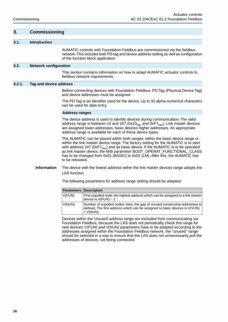
The following parameters for address range setting should be adapted:
DescriptionParametersFirst unpolled node; the highest address which can be assigned to a link masterdevice is V(FUN) – 1.
V(FUN)
Number of unpolled nodes; here, the gap of unused consecutive addresses isdefined. The first address which can be assigned to basic devices is V(VUN)+ V(NUN).
V(NUN)
Devices within the ‘Unused’ address range are excluded from communicating viaFoundation Fieldbus, because the LAS does not periodically check this range fornew devices. V(FUN) and V(NUN) parameters have to be adapted according to theaddresses assigned within the Foundation Fieldbus network, the "unused" rangeshould be selected in a way to ensure that the LAS does not unnecessarily poll theaddresses of devices, not being connected.
16
Actuator controlsCommissioning AC 01.2/ACExC 01.2 Foundation Fieldbus
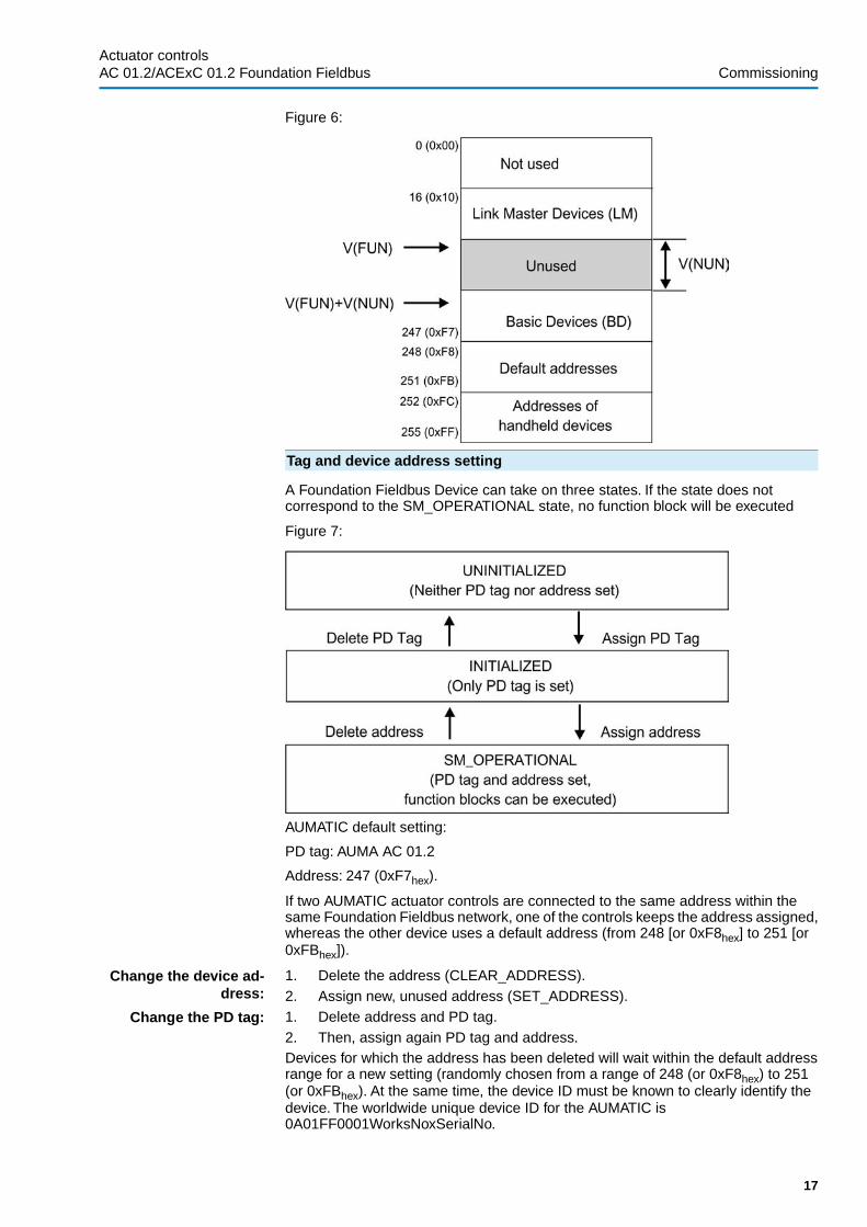
Figure 6:
Tag and device address setting
A Foundation Fieldbus Device can take on three states. If the state does notcorrespond to the SM_OPERATIONAL state, no function block will be executed
Figure 7:
AUMATIC default setting:
PD tag: AUMA AC 01.2
Address: 247 (0xF7hex).
If two AUMATIC actuator controls are connected to the same address within thesame Foundation Fieldbus network, one of the controls keeps the address assigned,whereas the other device uses a default address (from 248 [or 0xF8hex] to 251 [or0xFBhex]).
Change the device ad-dress:
1. Delete the address (CLEAR_ADDRESS).2. Assign new, unused address (SET_ADDRESS).
Change the PD tag: 1. Delete address and PD tag.2. Then, assign again PD tag and address.Devices for which the address has been deleted will wait within the default addressrange for a new setting (randomly chosen from a range of 248 (or 0xF8hex) to 251(or 0xFBhex). At the same time, the device ID must be known to clearly identify thedevice. The worldwide unique device ID for the AUMATIC is0A01FF0001WorksNoxSerialNo.
17
Actuator controls AC 01.2/ACExC 01.2 Foundation Fieldbus Commissioning

3.2.2. Link master parameter setting
To ensure stable communication, different parameters must be observed and adaptedto the connected link master devices. When setting the parameters in compliancewith table 16, the largest value of all devices connected to the same FoundationFieldbus network must be used.
Link master parameters of the AUMATIC:
DescriptionParametersSymbolTime necessary for an immediate device response (unit:1/256 µs). For the AUMATIC, set value ≥ 8.
Slot TimeV(ST)
Minimum time between two data telegrams (unit: 1/256 µs).For the AUMATIC, set value ≥ 6.
Minimum InterPDU Delay
V(MID)
Maximum time permissible for a response (unit: slot time(V(ST));For the AUMATIC, set value ≥ 5.
Maximum Re-sponse Delay
V(MRD)
3.2.3. Scheduling parameter setting
The process application is assembled using and combining function blocks. Thescheduling of the connected function blocks is precisely defined during configurationof the function block application.
The combined blocks have to be executed simultaneously with other blocks withinthe communication schedule. Communication synchronisation is performed via theLAS.
The MACROCYCLE_DURATION parameter is used to define the cycle time of thedevices connected to the network.
MACROCYCLE_DURATION specifies the macrocycle duration. The unit of thisparameter is 1/32 ms and the default value for the AUMATIC is 32000 (0x7D00hex= 1 s). This value can be optimised, if required.
3.3. Function blocks
Input and output parameter of function blocks can be connected to perform theautomation task via Foundation Fieldbus.
The AUMATIC contains the following function blocks:
DescriptionCodeUnitsResource BlockRB21
Analog Input function blockAI4
Discrete Input function blockDI10
Analog Output function blockAO2
Discrete Output function blockDO8
Process Controller function blockPID1
Signal Characteriser function blockSC1
Input Selector function blockIS1
Analog Input transducer blockAITB1
Discrete Input transducer blockDITB1
Discrete Output transducer blockDOTB1
Analog Output transducer blockAOTB1
Positioner Transducer Block (transducer block for controlling the ac-tuator)
PTB1
AUMA Commissioning Transducer Block (transducer block for com-missioning and parameter setting)
AUMACTB1
AUMA Diagnosis Transducer Block (Transducer Block for diagnostics)AUMADTB1
Each Discrete Input function block is connected to a common Discrete Inputtransducer block.
Each Analog Input function block is connected to a common Analog Input transducerblock.
18
Actuator controlsCommissioning AC 01.2/ACExC 01.2 Foundation Fieldbus

Depending on the channel configuration, the Discrete Output function block and theAnalog Output function block are either connected to the Positioner TransducerBlock, the Analog Output transducer block or the Discrete Output transducer block.For the PID function block, the IS function block, the SC function block and the RB2function block, no transducer blocks are required.
Figure 8: Function blocks
3.3.1. Operation commands
Operation of AUMA actuators with AUMATIC controls via Foundation Fieldbus canbe performed via the Analog Output function block (AO) for setpoint operationcommands or, alternatively, via the Discrete Output function block (DO) for OPEN -STOP - CLOSE commands.
Typically, actuators are either exclusively operated via an analog setpoint operationcommand of the Analog Output function block (AO) or, as an alternative, via binaryOPEN - CLOSE operation commands of the Discrete Output function blocks (DO).
Depending on the selected channel of the function block (CHANNEL parameter),received operation commands will either be processed by the Positioner TransducerBlock (PTB), the Discrete Output Transducer Block (DOTB) or the Analog OutputTransducer Block (AOTB), allowing for further settings such as dynamic change-overbetween an analog setpoint command and binary OPEN - CLOSE operationcommands.
Information As the actuator may be controlled via different channels (CHANNEL parameter),certain restrictions apply for CHANNEL parameter setting irrespective of the functionblock used. They will be described in detail for commissioning of the respectivefunction blocks.
Operation commands via Analog Output function block
The AO function block accepts setpoints between 0 and 100 %.
A setpoint of 0 % signifies that the actuator fully closes, a setpoint of 100 % signifies,that the actuator fully opens.
The integral PID function block can be used as controller function block to reducethe number of required external VCRs.This is not imperative.The PID function blockcan be integrated within another external device, e.g. the DCS; however, an additionalVCR is then required for feedback from the AO to the PID.
For setpoint control via an Analog Output function block (AO), the setpoint signal istypically forwarded to the Positioner Transducer Block. In this case, the AO canprovide additional information on the actual position and the actuator status andtherefore on the availability of the AO, when using the backward path (BKCAL_OUT).
19
Actuator controls AC 01.2/ACExC 01.2 Foundation Fieldbus Commissioning

Figure 9: Typical control via Analog Output function block
As an alternative, the setpoint signal can also be sent via the Analog Outputtransducer block. An additional Discrete Output function block then controls thechange-over between setpoint operation command and binary OPEN - CLOSEcommands.When using the above configuration, the AO will only provide the receivedsetpoint via its backward path (BKCAL_OUT), but no further feedback on actuatorposition or actuator status.
Figure 10: Alternative control via Analog Output function block with operation com-mand change-over via Discrete Output function block
Operation commands via Discrete Output function block
For binary control using a Discrete Output function block (DO), binary 8-bit operationcommands are typically also forwarded to the Positioner Transducer Block. In thiscase, the DO provides the received operation commands via its backward path(BKCAL_OUT_D), but also additional feedback on the actuator status and thereforeon the availability of the DO.
20
Actuator controlsCommissioning AC 01.2/ACExC 01.2 Foundation Fieldbus

Figure 11: Discrete Output function block
Table 2: Coding of 8-bit operation commands to the Positioner Transducer Block
DescriptionOperation commandDiscreteState
Running OPENFieldbus CLOSE0
Running CLOSEFieldbus OPEN1
Actuator stopsStop2
Actuator stopsStop3
–Reserved4 – 7
Run to intermediate position 1.Fieldbus intermediate position 18
Run to intermediate position 2.Fieldbus intermediate position 29
Run to intermediate position 3.Fieldbus intermediate position 310
Run to intermediate position 4.Fieldbus intermediate position 411
Run to intermediate position 5.Fieldbus intermediate position 512
Run to intermediate position 6.Fieldbus intermediate position 613
Run to intermediate position 7.Fieldbus intermediate position 714
Run to intermediate position 8.Fieldbus intermediate position 815
–Reserved16 – 255
As an alternative, Discrete Output function blocks (DO) can also forward operationcommands OPEN or CLOSE as well as further binary control commands using asingle bit format to the Discrete Output transducer block. When using this single bitconfiguration, DO will only provide the received binary signals via its backward path(BKCAL_OUT_D), but no further feedback on the actuator status.
21
Actuator controls AC 01.2/ACExC 01.2 Foundation Fieldbus Commissioning

Figure 12: Discrete Output function block
Information ● Selection of the single-bit format requires several DO function blocks as wellas several external VCRs, as just one operation command can be sent perconnection (e.g. either operation command OPEN or operation commandCLOSE). Value 0x00 is interpreted as logical 0, all other values as logical 1(the same applies when using the INVERT function)!
● When selecting the 8-bit format, several operation commands (e.g. operationcommands OPEN or CLOSE or intermediate position operation commands)can be transmitted using just one external VCR to a DO function block.
● To avoid conflicting commands, operation commands or control signals mustnot be transmitted over several channels, using different formats to the DOfunction blocks.
3.3.2. Feedback signals from AUMATIC actuator controls
The AUMATIC is able to indicate its status by means of several different functionblocks. The Analog Input function blocks (AI) are used to transmit analogue values,the Discrete Input function blocks (DI) are used to transmit binary information.
Feedback signals via the Analog Input function blocks
AUMATIC actuator controls are equipped with 4 Analog Input function blocks (AI).Depending on the channel selection (CHANNEL parameter), the following analoguefeedbacks signals can be transmitted:
● Actual actuator position (0.0 – 100.0%)● Input AIN 1 (optional external analogue 0 – 20 mA input, connection terminals
AIN1+/AIN1–)● Actuator torque (0.0 – 100.0 %; value 0.0 % corresponds to 127 % of the
nominal torque in direction CLOSE, 100.0 % corresponds to 127 % of thenominal torque in direction OPEN)
● Input AIN 2 (optional external analogue 0 – 20 mA input, connection terminalsAIN2+/AIN2–)
For the Analog Input function blocks (AI), there is a common Analog Input TransducerBlock (AITB) providing additional configuration options.
Feedback signals via Discrete Input function blocks
AUMATIC controls have 10 Discrete Input function blocks (DI). Depending on thechannel selection (CHANNEL parameter), they can be used for different binaryfeedback signals in single-bit or 8-bit format. For the Discrete Input function blocks(DI), there is a common Discrete Input Transducer Block (DITB) providing additionalconfiguration options.
22
Actuator controlsCommissioning AC 01.2/ACExC 01.2 Foundation Fieldbus

3.3.3. Function block parameter setting
The following steps should be performed in the order as indicated to configure abasic function block application. Some parameter settings may depend on the typeof application or the control system.
Uniform parameters for all blocks
All blocks contain six general parameters. They are: ST_REV, TAG_DESC,STRATEGY, ALERT_KEY, MODE_BLK and BLOCK_ERR:
ST_REV Revision status of the static data associated with the function block. For better trackingof changes within the static parameter, the ST_REV of the associated blocks isincremented by one as soon as a static parameter attribute is changed.The ST_REVof the block is also incremented by one if static parameter attribute is written, howeverthe value itself remains unchanged.The value is reset to 0 as soon as the RESTARTparameter is written with “Defaults (3)".
TAG_DESC This parameter can be used for describing the appropriate block application. Thevalue is reset to the factory settings as soon as as soon as the RESTART parameteris written with “Defaults (3)".
STRATEGY The strategy field can be used to identify a grouping of blocks.The data is not checkedor processed by the block but used by the higher ranking system to classify thefunction blocks.
ALERT_KEY ID number of plant unit. A common ALERT_KEY can be assigned to all deviceswithin a circuit or a plant segment to help the user to classify faults. Each block hasits own ALERT_KEY being transmitted with every block-specific alarm signal.
The control system can use this information to sort alarm signals, e.g. as code foridentifying and classifying the source of the alarm signal. If the ALERT_KEY is notused, occurring fault signals cannot be sent to a certain user console. TheALERT_KEY defines the destination of the alarm signal transfer of this block (towhich user console).
The use of this parameter is strongly recommended!
MODE_BLK This parameter includes the actual, target, permitted, and normal block operationmodes.
● TARGET: changes the block operation mode● ACTUAL: indicates the current block operation mode● PERMITTED: indicates the permissible operation modes● NORMAL: indicates the normal block operation modeRefer to appendix "Block operation modes" (contains detailed information aboutpossible function block conditions).
BLOCK_ERR This parameter reflects the fault state of hardware and software componentsassociated with a block. It contains bit string, therefore several errors can be displayedat the same time.
Resource Block (RESOURCE)
The resource block stores device hardware information related to all function blockswithin a device (such as e.g. memory size) and controls the device hardware as wellas the internal function blocks. Furthermore, it contains the device name,manufacturer, and serial number.
Apart from the diagnostic signals in accordance with NAMUR recommendation NE107 as well as the representation of these signals in accordance with FF SpecificationField Diagnostics Profile, FF-912.pdf , the resource block additionally containsessential information of the specific electronic name plate of the AUMATIC:
23
Actuator controls AC 01.2/ACExC 01.2 Foundation Fieldbus Commissioning

ExplanationsResource Block parametersIDENTIFICATION
Device descriptionIDENT_DEVICE_DESIGNATION
Device tagIDENT_DEVICE_TAG
Project nameIDENT_PROJECT_NAME
CONTROLS_IDENTIFIER
Controls commission numberCTRLS_COMMISSION_NO
Controls works numberCTRLS_WORKS_NO
Controls wiring diagramCTRLS_WIRING_DIAGRAM
Production dateCTRLS_DATE_OF_MANUFACTURE
ACTUATOR_IDENTIFIER
Actuator commission numberACT_COMMISSION_NO
Actuator works numberACT_WORKS_NO
Actuator wiring diagramACT_WIRING_DIAGRAM
Commissioning:
1. Lock/unlock write protection:Parameter: WRITE_LOCK- LOCKED = Write protection activated (no write access to any changeable
parameters)- NOT LOCKED = Write protection deactivated (factory setting)
2. Enter or change block name (if required):Factory setting = "Resource ItemNo-SerialNoFF“
3. Set operation mode in MODE_BLK parameter group (TARGET parameter) toOOS (Out_Of_Service).
4. To delete a possibly existing function block application, if applicable, write“Defaults (3)" to the RESTART parameter.Trend, link and alert objects will thenbe deleted and function blocks will be reset to their default values. Device ad-dress and tags will be retained (for further details on the RESTART parameter,refer to appendix).
24
Actuator controlsCommissioning AC 01.2/ACExC 01.2 Foundation Fieldbus

5. Verify and adapt settings of NAMUR recommendation NE 107 Field Diagnostics,if required.The following parameters may be used for configuration of the indic-ations.
Factory settingField Diagnostics parameters-FD_FAIL_ACTIVE
-FD_OFFSPEC_ACTIVE
-FD_MAINT_ACTIVE
-FD_CHECK_ACTIVE
0xFFC2 0001FD_FAIL_MAP
0x003D F901FD_OFFSPEC_MAP
0x0000 0401FD_MAINT_MAP
0x0000 02FFFD_CHECK_MAP
0FD_FAIL_MASK
0FD_OFFSPEC_MASK
0FD_MAINT_MASK
0FD_CHECK_MASK
UninitializedFD_FAIL_ALM
UninitializedFD_OFFSPEC_ALM
UninitializedFD_MAINT_ALM
UninitializedFD_CHECK_ALM
0FD_FAIL_PRI
0FD_OFFSPEC_PRI
0FD_MAINT_PRI
0FD_CHECK_PRI
0/0/DisableFD_SIMULATE
Not InitializedFD_RECOMMEND_ACT
-FD_EXTENDED_ACTIVE_1
-FD_EXTENDED_ACTIVE_2
-FD_EXTENDED_ACTIVE_3
-FD_EXTENDED_ACTIVE_4
-FD_EXTENDED_ACTIVE_5
0x0000 1FFBFD_EXTENDED_MAP_1
0x0000 0100FD_EXTENDED_MAP_2
0xC000 0003FD_EXTENDED_MAP_3
0x0000 0080FD_EXTENDED_MAP_4
0x0000 0000FD_EXTENDED_MAP_5
6. Set operation mode in MODE_BLK parameter group (TARGET parameter) toAUTO. As the resource block contains the general operation mode of aFoundation Fieldbus device, the MODE_BLK parameter must be set to AUTOto allow commissioning of another AUMATIC function block during operation.
Analog Output function block (AO)
The AO receives an analogue signal from an upstream block and passes it on eitheras setpoint operation command to the Positioner Transducer Block (PTB) or asgeneral analogue signal to the Analog Output Transducer Block (AOTB). The mainfunctions of the AO function block comprise:
● Scaling● Value limiters – for both the value and change rate● Simulation● Actions upon deviations of upstream blocks
25
Actuator controls AC 01.2/ACExC 01.2 Foundation Fieldbus Commissioning

Figure 13: Analog Output function block
The AO performs bi-directional signal processing:
Main function:
Transmission of an analogue value from CAS_IN input via OUT output to PTB orAOTB (forward direction, controlled via CHANNEL parameter).
Secondary function:
Feedback to the upstream function block via BKCAL_OUT output (backwarddirection). The contents of this feedback signal depend on the channel selected(CHANNEL parameter) and the Use PV for BKCAL_OUT option of the IO_OPTSparameter.
Commissioning:
1. Enter or change block name (if required):Factory setting = “AO_x ItemNo-SerialNoFF”
2. Set operation mode in MODE_BLK parameter group (TARGET parameter) toOOS (Out_Of_Service).
3. Set CHANNEL parameter according to desired use.Refer to "CHANNEL parameter settings for Analog Output function block (AO)"table at the end of this section.
4. It is recommended to activate the following options for the IO_OPTS parameter:- SP-PV Track in Man- SP-PV Track in LO- SP Track retained target (SP tracks RCas or Cas if LO or Man)- and, if applicable, when using the PTB: Use PV for BKCAL_OUTRefer to appendix: IO_OPTS, availability and descriptionInformation: A torque fault causes the AO to enter IMan operation mode. Toeliminate this torque fault by issuing an AO counter command, ‘SP Track re-tained target’ must be set; Otherwise, the actuator may only be operated intothe opposite direction using the operation commands of the local controls. Ifthe current torque is lower than the preset tripping torque, the torque fault canbe reset as follows:- Either on the local controls using push button Reset (in selector switch
position LOCAL),- or via FF using a DO with CHANNEL= Ch DOTB fieldbus RESET.
5. The following option of the SHED_OPT parameter should be activated:- NormalShed_NormalReturn
6. Further AO parameters can now be configured or changed (if required).7. Set operation mode in MODE_BLK parameter group (TARGET parameter) to
CASCADE.
26
Actuator controlsCommissioning AC 01.2/ACExC 01.2 Foundation Fieldbus

8. Check/ perform configuration of the respective transducer block (refer to sectionPositioner Transducer Block (PTB) or Analog Output Transducer Block (AOTB)).
Information 'Ch PTB setpoint position‘ channel can only be selected once and excludes the useof 'Ch PTB operation commands [8 bit]‘ as well as 'Ch DOTB fieldbus OPEN‘, 'ChDOTB fieldbus CLOSE‘ and 'Ch DOTB fieldbus STOP‘ channels of the DO.
Table 3: CHANNEL parameter settings for Analog Output function block (AO)
AO.READBACK parameterExplanationUsed Trans-ducer Block
ValueCHANNELparameter
Not used(factory setting)
-0Ch notused
Value and status:PTB.PRIMARY_VALUE_ACTUAL_POSITION
Fieldbus setpoint positionPTB1Ch PTBsetpoint po-sition
Value and status:PTB.FINAL_VALUE_TARGET_SPEED
Reserved for future extensionsPTB3Ch PTBspeed
Value and status:AOTB.FINAL_VALUE_ANALOG_OUT_1
Analog_Out 1 (Verify/performfurther settings in AOTB para-meter CFG_AOUT_1)
AOTB20Ch AOTBAna-log_Out 1
Value and status:AOTB.FINAL_VALUE_ANALOG_OUT_2
Analog_Out 2 (Verify/performfurther settings in AOTB para-meter CFG_AOUT_2)
AOTB21Ch AOTBAna-log_Out 2
Discrete Output function block (DO)
The DO receives an analogue signal from an upstream block and passes it on eitheras operation command to the Positioner Transducer Block (PTB) or as general binarysignal to the Discrete Output Transducer Block (DOTB). The main functions of theDO function block comprise:
● Simulation● Actions upon deviations of upstream blocks● Signal inversion● Feedback signal via backward path (BKCAL_OUT_D)
Figure 14: Discrete Output function block (DO)
The DO also performs bi-directional signal processing:
Main function:
Transmission of a binary value from CAS_IN_D input via OUT_D output to PTB orDOTB (forward direction, controlled via CHANNEL parameter).
Secondary function:
Feedback signal to the upstream function block via BKCAL_OUT_D output (backwarddirection). The contents of this feedback signal depend on the channel selected
27
Actuator controls AC 01.2/ACExC 01.2 Foundation Fieldbus Commissioning

(CHANNEL parameter) and the Use PV for BKCAL_OUT option of the IO_OPTSparameter.
Commissioning:
1. Enter or change block name (if required):Factory setting = "DO_x ItemNo-SerialNoFF“
2. Set operation mode in MODE_BLK parameter group (TARGET parameter) toOOS (Out_Of_Service).
3. Set CHANNEL parameter according to desired use.Refer to "CHANNEL parameter settings for Discrete Output function block (DO)"table at the end of this section.Information: Conflicting operation commands or control signals are not permit-ted. For this reasons operation commands or control signals must not betransmitted several times using several DO function blocks and different chan-nels.
4. It is recommended to activate the following options for the IO_OPTS parameter:- SP-PV Track in Man- SP-PV Track in LO- SP Track retained target (SP tracks RCas or Cas if LO or Man)- and, if applicable, when using the PTB: Use PV for BKCAL_OUTRefer to appendix: IO_OPTS, availability and descriptionInformation: A torque fault causes the DO to enter IMan operation mode. Toeliminate this torque fault by issuing a DO counter command, ‘SP Track retainedtarget’ must be set; Otherwise, the actuator may only be operated into the op-posite direction using the operation commands of the local controls.If the current torque is lower than the preset tripping torque, the torque faultcan be reset as follows:- Either on the local controls using push button Reset (in selector switch
position LOCAL),- or via FF using a DO with CHANNEL= Ch DOTB fieldbus RESET.
5. The following option of the SHED_OPT parameter should be activated:- NormalShed_NormalReturn
6. Further DO parameters can now be configured or changed (if required).7. Set operation mode in MODE_BLK parameter group (TARGET parameter) to
CASCADE.8. Check/perform configuration of the respective transducer block (refer to section
Positioner Transducer Block (PTB) or Discrete Output Transducer Block(DOTB)).
Information ● Ch PTB operation commands [8 bit]‘ channel can only be selected once andexcludes the use of 'Ch DOTB fieldbus OPEN‘, 'Ch DOTB fieldbus CLOSE‘ and'Ch DOTB fieldbus STOP‘ channels. In this case, 'Ch PTB setpoint position‘channel of the AO is also excluded.
● Channels 'Ch DOTB fieldbus OPEN‘, 'Ch DOTB fieldbus CLOSE‘ and 'Ch DOTBfieldbus STOP‘ can be selected once each and exclude the use of the 'Ch PTBoperation commands [8 bit]‘ channel. In this case, 'Ch PTB setpoint position‘channel of the AO is also excluded.
28
Actuator controlsCommissioning AC 01.2/ACExC 01.2 Foundation Fieldbus

Table 4: CHANNEL parameter settings for Discrete Output function block (DO)
DO.READBACK_D parameterExplanationUsed Trans-ducer Block
ValueCHANNELparameter
Not used(factory setting)
-0Ch notused
Value:PTB.FINAL_VALUE_COMMANDSStatus:PTB.PRIMARY_VALUE_ACTUAL_POSITION
Operation commands:Value 0: Fieldbus CLOSEValue 1: Fieldbus OPENValue 2: StopValue 3: StopValues 4 – 7 ReservedValue 8: Fieldbus intermediate position1Value 9: Fieldbus intermediate position2Value 10: Fieldbus intermediate posi-tion 3Value 11: Fieldbus intermediate posi-tion 4Value 12: Fieldbus intermediate posi-tion 5Value 13: Fieldbus intermediate posi-tion 6Value 14: Fieldbus intermediate posi-tion 7Value 15: Fieldbus intermediate posi-tion 8Values 16 – 255: Reserved
PTB2Ch PTB op-erationcommands[8 bit]
Value and status:DOTB.FINAL_VALUE_DIGITAL_OUTPUTS
Digital outputs:Bit 0: Fieldbus DOUT 1Bit 1: Fieldbus DOUT 2Bit 2: Fieldbus DOUT 3Bit 3: Fieldbus DOUT 4Bit 4: Fieldbus DOUT 5Bit 5: Fieldbus DOUT 6Bits 6 and 7: Reserved
DOTB4Ch DOTBdigital out-put [8 bit]
Value and status:DOTB.FINAL_VALUE_ADDITIONAL_COMMANDS
Additional commands:Bit 0: Fieldbus enable LOCALBit 1: Fieldbus Interlock OPENBit 2: Fieldbus Interlock CLOSEBit 3: ReservedBit 4: Fieldbus channel 1Bit 5: Fieldbus channel 2Bit 6: Fieldbus EMCYBit 7: PVST
DOTB5Ch DOTBadditionalcommands[8 bit]
Value and status:DOTB.FINAL_VALUE_FIELDBUS_OPEN
Fieldbus OPENDOTB6Ch DOTBfieldbusOPEN
Value and status:DOTB.FINAL_VALUE_FIELDBUS_CLOSE
Fieldbus CLOSEDOTB7Ch DOTBfieldbusCLOSE
Value and status:DOTB.FINAL_VALUE_FIELDBUS_STOP
Fieldbus STOPDOTB8Ch DOTBfieldbusSTOP
Value and status:DOTB.FINAL_VALUE_FIELDBUS_EMCY
Fieldbus EMCYDOTB9Ch DOTBfieldbusEMER-GENCY
Value and status:DOTB.FINAL_VALUE_FIELDBUS_RESET
Fieldbus RESETDOTB10Ch DOTBfieldbusRESET
Value and status:DOTB.FINAL_VALUE_FIELDBUS_ENABLE_OPEN
Fieldbus Interlock OPENDOTB11Ch DOTBfieldbus en-able OPEN
29
Actuator controls AC 01.2/ACExC 01.2 Foundation Fieldbus Commissioning

DO.READBACK_D parameterExplanationUsed Trans-ducer Block
ValueCHANNELparameter
Value and status:DOTB.FINAL_VALUE_FIELDBUS_ENABLE_CLOSE
Fieldbus Interlock CLOSEDOTB12Ch DOTBfieldbus en-ableCLOSE
Value and status:DOTB.FINAL_VALUE_FIELDBUS_ENABLE_LOCAL
Fieldbus enable LOCALDOTB13Ch DOTBfieldbus en-able LOC-AL
Value and status:DOTB.FINAL_VALUE_FF_OUT1
Digital_Out 1 (Verify/perform furthersettings in DOTB parameterCFG_DOUT_1)
DOTB14Ch DOTBDigital_Out1
Value and status:DOTB.FINAL_VALUE_FF_OUT2
Digital_Out 2 (Verify/perform furthersettings in DOTB parameterCFG_DOUT_2)
DOTB15Ch DOTBDigital_Out2
Value and status:DOTB.FINAL_VALUE_FF_OUT3
Digital_Out 3 (Verify/perform furthersettings in DOTB parameterCFG_DOUT_3)
DOTB16Ch DOTBDigital_Out3
Value and status:DOTB.FINAL_VALUE_FF_OUT4
Digital_Out 4 (Verify/perform furthersettings in DOTB parameterCFG_DOUT_4)
DOTB17Ch DOTBDigital_Out4
Value and status:DOTB.FINAL_VALUE_FF_OUT5
Digital_Out 5 (Verify/perform furthersettings in DOTB parameterCFG_DOUT_5)
DOTB18Ch DOTBDigital_Out5
Value and status:DOTB.FINAL_VALUE_FF_OUT6
Digital_Out 6 (Verify/perform furthersettings in DOTB parameterCFG_DOUT_6)
DOTB19Ch DOTBDigital_Out6
Transducer blocks
Transducer blocks decouple standardised FF function blocks from specific input andoutput functions of an FF field device.
Output Transducer Blocks of the AUMATIC controls, i.e. PTB, AOTB and DOTB,additionally offer the MAN (Manual) operation mode apart from the typical operationmodes OSS (Out_Of_Service) and AUTO (Automatic). In the MAN (Manual) operationmode, the user can operate the actuator manually without using possibly activatedand connected function blocks.
Furthermore, output transducer blocks are equipped with a backward path fortransmission of a value including status to the READBACK or READBACK_Dparameters of the upstream function blocks AO or DO.
Positioner Transducer Block (PTB)
Among others, the Positioner Transducer Block (PTB) contains XD_ERROR andXD_ERREXT error variables (for details on the error codes, refer to appendix) aswell as the ACTIVE_CHANNEL parameter of the currently used channel (for details,refer to appendix).
Depending on the channel used, different value and status information is sent asfeedback to the AO.READBACK or the DO.READBACK_D parameters:
READBACK / READBACK_D parametersExplanationValueCHANNELValue and statusAO.READBACK = PTB.PRIMARY_VALUE_ACTU-AL_POSITION
Analoguesetpoint posi-tion
1Ch PTB set-point position
ValueDO_READBACK_D = PTB.FINAL_VALUE_COM-MANDSStatusDO_READBACK_D = PTB.PRIMARY_VALUE_ACTU-AL_POSITION
Binary opera-tion com-mands
2Ch PTB set-point position
Value and statusAO_READBACK = PTB.FINAL_VALUE_TAR-GET_SPEED
Reserved forfuture exten-sions
3Ch PTBspeed
30
Actuator controlsCommissioning AC 01.2/ACExC 01.2 Foundation Fieldbus

Commissioning:
1. Enter or change block name (if required): Factory setting = "Positioner_TBItemNo-SerialNoFF“.
2. Set operation mode in MODE_BLK parameter group (TARGET parameter) toOOS (Out_Of_Service).Now, the PTB parameters can be configured or changed (if required).
3. Set operation mode in MODE_BLK parameter group (TARGET parameter) toAUTO.
Analog Output Transducer Block (AOTB)
Among others, the Analog Output Transducer Block (AOTB) contains XD_ERRORand XD_ERREXT error variables (for details on the error codes, refer to appendix)and offers additional configuration options for the analogue signals received via thechannel of the AO function blocks.
Both value and status of the analogue signal received via the respective channel(FINAL_VALUE_ANALOG_OUT_1 or FINAL_VALUE_ANALOG_OUT_2) are sentas return values to the AO.READBACK parameter.
Commissioning:
1. Enter or change block name (if required): Factory setting = "AnalogOut_TBItemNo-SerialNoFF“.
2. Set operation mode in MODE_BLK parameter group (TARGET parameter) toOOS (Out_Of_Service).
3. Verify or adapt CFG_AOUT_1 or CFG_AOUT_2 parameter settings:
ExplanationsValueCFG_AOUT_1orCFG_AOUT_2parameters
TransducerBlock
Fieldbus setpoint position0Fieldbus set-point position
AOTB
Reserved for future extensions1Fieldbus speed
Fieldbus actual process value (for optional internalPID controller function)
2Fieldbus actualprocess value
Fieldbus output AOUT 13Fieldbus outputAOUT 1
Fieldbus output AOUT 24Fieldbus outputAOUT 2
Configurable analogue output 1 (for future exten-sions)
11Analog_Out 1(Cfg)
Configurable analogue output 2 (for future exten-sions)
12Analog_Out 2(Cfg)
Factory settings:CFG_AOUT_1 = Fieldbus output AOUT 1CFG_AOUT_2 = Fieldbus output AOUT 2
4. Set operation mode in MODE_BLK parameter group (TARGET parameter) toAUTO.
Discrete Output Transducer Block (DOTB)
Among others, the Discrete Output Transducer Block (DOTB) contains XD_ERRORand XD_ERREXT error variables (for details on the error codes, refer to appendix)and offers additional configuration options for the binary signals received via thechannels of the DO blocks.
Both value and status of the binary signals received via the respective channel aresent as return values to the DO.READBACK_D parameter.
Commissioning:
1. Enter or change block name (if required): Factory setting = "DiscreteOut_TBItemNo-SerialNoFF“.
31
Actuator controls AC 01.2/ACExC 01.2 Foundation Fieldbus Commissioning

2. Set operation mode in MODE_BLK parameter group (TARGET parameter) toOOS (Out_Of_Service).
3. Verify or adapt CFG_DOUT_1 to CFG_DOUT_6 parameter settings:
ExplanationsValueCFG_DOUT_1 toCFG_DOUT_6parameters
TransducerBlock
Not used0Not usedDOTB
Run to setpoint; in this case, the setpointmust be transmitted via an AO with channel= Ch AOTB Analog Out 1 or Ch AOTB Ana-log Out 2.
1Fieldbus SETPOINT
Change over to fieldbus channel 12Fieldbus channel 1
Change over to fieldbus channel 23Fieldbus channel 2
Execute (PVST) Partial Valve Stroke Test4Fieldbus PVST
Operation command:Run to intermediate position 1.
5Fieldbus intermedi-ate position 1
Operation command:Run to intermediate position 2.
6Fieldbus intermedi-ate position 2
Operation command:Run to intermediate position 3.
7Fieldbus intermedi-ate position 3
Operation command:Run to intermediate position 4.
8Fieldbus intermedi-ate position 4
Operation command:Run to intermediate position 5.
9Fieldbus intermedi-ate position 5
Operation command:Run to intermediate position 6.
10Fieldbus intermedi-ate position 6
Operation command:Run to intermediate position 7.
11Fieldbus intermedi-ate position 7
Operation command:Run to intermediate position 8.
12Fieldbus intermedi-ate position 8
Activate digital output 113Fieldbus DOUT 1
Activate digital output 214Fieldbus DOUT 2
Activate digital output 315Fieldbus DOUT 3
Activate digital output 416Fieldbus DOUT 4
Activate digital output 517Fieldbus DOUT 5
Activate digital output 618Fieldbus DOUT 6
Configurable digital output 1 (for future exten-sions)
19Digital_Out 1 (Cfg)
Configurable digital output 2 (for future exten-sions)
20Digital_Out 2 (Cfg)
Configurable digital output 3 (for future exten-sions)
21Digital_Out 3 (Cfg)
Configurable digital output 4 (for future exten-sions)
22Digital_Out 4 (Cfg)
Configurable digital output 5 (for future exten-sions)
23Digital_Out 5 (Cfg)
Configurable digital output 6 (for future exten-sions)
24Digital_Out 6 (Cfg)
Factory settings:CFG_DOUT_1 = Not usedCFG_DOUT_2 = Not usedCFG_DOUT_3 = Not usedCFG_DOUT_4 = Not usedCFG_DOUT_5 = Not usedCFG_DOUT_6 = Not used
4. Set operation mode in MODE_BLK parameter group (TARGET parameter) toAUTO.
32
Actuator controlsCommissioning AC 01.2/ACExC 01.2 Foundation Fieldbus

Analog Input function block (AI)
An AI receives an analogue signal from a transducer block of the field device andmakes the signal available to the other FF field devices as FF signal. The mainfunctions of the AI function block comprise:
● Signal inversion● Simulation● Signal testing and alarm generation● Scaling
Figure 15: Analog Input Funktionsblock (AI)
Die AUMATIC besitzt insgesamt vier Analog Input Funktionsblöcke (AI) die je nachKonfiguration (Parameter CHANNEL) unterschiedliche Rückmeldungen am AusgangOUT zur Verfügung stellen können.
Commissioning:
1. Enter or change block name (if required): Factory setting = "AI_x ItemNo-Seri-alNoFF“
2. Set operation mode in MODE_BLK parameter group (TARGET parameter) toOOS (Out_Of_Service).
3. Set CHANNEL parameter according to desired use.Refer to "CHANNEL parameter settings for Analog Input function block (AI)"table at the end of this section.
4. Use L_TYPE parameter to select the linearisation type for the input value (Direct,Indirect, Indirect Sq Root), recommendation: DirectInformation: For 'Direct‘ linearisation type, the configuration of the OUT_SCALEparameter group must correspond the configuration of the XD_SCALE parametergroup; otherwise, the block operation mode cannot be set to AUTO. Incorrectconfiguration is indicated via the BLOCK_ERROR parameter (‘Block Configur-ation Error’).
5. If required, the following parameters can be used to define limit values for alarmand warning signals as well as the priorities of these signals (the limit valuesmust be within the value range specified in the OUT_SCALE parameter group):- HI_HI_LIM- HI_LIM- LO_LIM- LO_LO_LIM- HI_HI_PRI- HI_PRI- LO_PRI- LO_LO_PRI
33
Actuator controls AC 01.2/ACExC 01.2 Foundation Fieldbus Commissioning

6. Set operation mode in MODE_BLK parameter group (TARGET parameter) toAUTO.
Table 5: CHANNEL parameter settings for Analog Input function block (AI)
ExplanationUsed Trans-ducer Block
ValueCHANNEL
Not used(factory setting)
–0Ch not used
Analog_In 1(Verify/perform further settings in AITB parameterCFG_AIN_1, factory setting ofCFG_AIN_1: Actual position of the actuator)
AITB67Ch AITB Analog_In 1
Analog_In 2(Verify/perform further settings in AITB parameterCFG_AIN_2, factory setting ofCFG_AIN_2: Input AIN 1
AITB68Ch AITB Analog_In 2
Analog_In 3(Verify/perform further settings in AITB parameterCFG_AIN_3, factory setting ofCFG_AIN_3: actuator torque)
AITB69Ch AITB Analog_In 3
Analog_In 4(Verify/perform further settings in AITB parameterCFG_AIN_4, factory setting ofCFG_AIN_4: Input AIN 2)
AITB70Ch AITB Analog_In 4
Analog Input Transducer Block (AITB)
Apart from the analogue values of the actual position, the torques and the two optionalinputs, the Analog Input Transducer Block (AITB) contains among others theXD_ERROR and XD_ERREXT error variables (for details on the error codes, referto the appendix) and provides additional configuration options for the analoguesignals to be transmitted to the AI function blocks via the channels.
Commissioning:
1. Enter or change block name (if required): Factory setting = "AnalogIn_TBItemNo-SerialNoFF“.
2. Set operation mode in MODE_BLK parameter group (TARGET parameter) toOOS (Out_Of_Service).
3. Verify or adapt CFG_AIN_1 to CFG_AIN_4 parameter setting:
ExplanationsValueCFG_AIN_1 toCFG_AIN_4parameters
Actual actuator position (0.0 – 100.0%)0Actual position
Input AIN 1 (optional external analogue 0 – 20 mAinput, connection terminals AIN1+/AIN1–)
1Analogue input 1
Actuator torque (0.0 – 100.0 %; value 0.0 % corres-ponds to 127 % of the nominal torque in directionCLOSE, 100.0 % corresponds to 127 % of the nominaltorque in direction OPEN)
2Torque
Input AIN 2 (optional external analogue 0 – 20 mAinput, connection terminals AIN2+/AIN2–)
3Analogue input 2
Configurable analogue input 1 (for future extensions)4Analog_In 1 (Cfg)
Configurable analogue input 2 (for future extensions)5Analog_In 2 (Cfg)
Configurable analogue input 3 (for future extensions)6Analog_In 3 (Cfg)
Configurable analogue input 4 (for future extensions)7Analog_In 4 (Cfg)
Factory settings:CFG_AIN_1 = Actual positionCFG_AIN_2 = Analogue input 1CFG_AIN_3 = TorqueCFG_AIN_4 = Analog input 2
4. Set operation mode in MODE_BLK parameter group (TARGET parameter) toAUTO.
34
Actuator controlsCommissioning AC 01.2/ACExC 01.2 Foundation Fieldbus

Discrete Input function block (DI)
A DI receives an analogue signal from a transducer block of the field devices andmakes the signal available to the other FF field devices as FF signal. The mainfunctions of the DI function block comprise:
● Signal inversion● Simulation● Filtering (time delay)● Generation of alarms
Figure 16: Discrete Input function block (DI)
AUMATIC controls have all in all ten Discrete Input function blocks (DI). Dependingon the configuration (CHANNEL parameter), different binary feedback signals insingle-bit or 8-bit format can be provided at output OUT_D.
Commissioning:
1. Enter or change block name (if required): Factory settinng = "DI_x ItemNo-SerialNoFF“
2. Set operation mode in MODE_BLK parameter group (TARGET parameter) toOOS (Out_Of_Service).
3. Set CHANNEL parameter according to desired use.Refer to "CHANNEL parameter settings for Discrete Input function block (DI)"table at the end of this section.
4. Set operation mode in MODE_BLK parameter group (TARGET parameter) toAUTO.
5. Verify or adapt configuration of the pertaining Discrete Input Transducer Block(refer to section below).
Table 6: CHANNEL parameter settings for Discrete Input function block (DI)
ExplanationUsed Trans-ducer Block
ValueCHANNEL parameter
Not used(factory setting)
-0Ch not used
Logical signalsDITB22Ch DITB logic signals [8 bit]
Bit 0: End position OPEN
Bit 1: End position CLOSED
Bit 2: Setpoint position reached
Bit 3: Not ready REMOTE
Bit 4: Running OPEN
Bit 5: Running CLOSE
Bit 6: Warnings
Bit 7: Fault
35
Actuator controls AC 01.2/ACExC 01.2 Foundation Fieldbus Commissioning

ExplanationUsed Trans-ducer Block
ValueCHANNEL parameter
Actuator signalsDITB23Ch DITB actuator signals [8 bit]
Bit 0: Thermal fault
Bit 1: Phase failure
Bit 2: Selector sw. REMOTE
Bit 3: Selector sw. LOCAL
Bit 4: Limit switch OPEN
Bit 5: Limit switch CLOSED
Bit 6: Torque switch OPEN
Bit 7: Torque switch CLOSE
Device statusDITB24Ch DITB device status [8 bit]
Bit 0: Not ready REMOTE
Bit 1: Warnings
Bit 2: Fault
Bit 3: Maintenance required
Bit 4: Out of specification
Bit 5: Function check
Bit 6: Failure
Bit 7: Device ok
Operation statusDITB25Ch DITB operation status [8bit] Bit 0: Op. pause active
Bit 1: In intermed. position
Bit 2: Start stepping mode
Bit 3: -
Bit 4: Actuator running
Bit 5: Handwheel oper.
Bit 6: Running REMOTE
Bit 7: Running LOCAL
Intermediate positionsDITB26Ch DITB intermediate positions[8 bit] Bit 0: Intermediate pos. 1
Bit 1: Intermediate pos. 2
Bit 2: Intermediate pos. 3
Bit 3: Intermediate pos. 4
Bit 4: Intermediate pos. 5
Bit 5: Intermediate pos. 6
Bit 6: Intermediate pos. 7
Bit 7: Intermediate pos. 8
Discrete inputsDITB27Ch DITB discrete inputs [8 bit]
Bit 0: Input DIN 1
Bit 1: Input DIN 2
Bit 2: Input DIN 3
Bit 3: Input DIN 4
Bit 4: Input DIN 5
Bit 5: Input DIN 6
Bits 6, 7: -
36
Actuator controlsCommissioning AC 01.2/ACExC 01.2 Foundation Fieldbus

ExplanationUsed Trans-ducer Block
ValueCHANNEL parameter
Not ready REMOTE 1DITB28Ch DITB not ready REMOTE1 [8 bit] Bit 0: Wrong oper. cmd
Bit 1: Sel. sw. not REMOTE
Bit 2: Interlock active
Bit 3: Local STOP
Bit 4: EMCY STOP act.
Bit 5: EMCY behav. active
Bit 6: FailState fieldbus
Bit 7: I/O interface
Not ready REMOTE 2DITB29Ch DITB not ready REMOTE2 [8 bit] Bit 0.1: -
Bit 2: SIL function active
Bit 3: Disabled
Bit 4: Interlock by-pass
Bit 5: PVST active
Bit 6: Service active
Bit 7: Handwheel active
Fault 1DITB30Ch DITB fault 1 [8 bit]
Bit 0: Configuration error
Bit 1: Mains quality
Bit 2: Thermal fault
Bit 3: Phase failure
Bit 4: Torque fault OPEN
Bit 5: Torque fault CLOSE
Bit 6: Internal error
Bit 7: No reaction
Fault 2DITB31Ch DITB fault 2 [8 bit]
Bit 0-5: -
Bit 6: Config. error REMOTE
Bit 7: Incorrect phase seq
Warnings 1DITB32Ch DITB warnings 1 [8 bit]
Bit 0-3: -
Bit 4: Torque wrn CLOSE
Bit 5: Torque wrn OPEN
Bit 6: SIL fault
Bit 7: Wrn no reaction
Warnings 2DITB33Ch DITB warnings 2 [8 bit]
Bit 0: Wrn controls temp.
Bit 1.2: -
Bit 3: 24 VDC external
Bit 4: -
Bit 5: RTC button cell
Bit 6: RTC not set
Bit 7: Config. warning
37
Actuator controls AC 01.2/ACExC 01.2 Foundation Fieldbus Commissioning

ExplanationUsed Trans-ducer Block
ValueCHANNEL parameter
Warnings 3DITB34Ch DITB warnings 3 [8 bit]
Bit 0.1: -
Bit 2: Warning input AIN 2
Bit 3: Warning input AIN 1
Bit 4: Internal warning
Bit 5: Wrn on time starts
Bit 6: Wrn on time running
Bit 7: Op. time warning
Warnings 4DITB35Ch DITB warnings 4 [8 bit]
Bit 0.1: -
Bit 2: Wrn setpoint position
Bit 3: PVST required
Bit 4: -
Bit 5: Failure behav. active
Bit 6: PVST abort
Bit 7: PVST fault
FailureDITB36Ch DITB failure [8 bit]
Bits 0 – 6: -
Bit 7: Fault
Maintenance requiredDITB37Ch DITB maintenance required[8 bit] Bits 0 – 6: -
Bit 7: Maintenance required
Out of specification 1DITB38Ch DITB out of specification 1[8 bit] Bits 0 – 6: -
Bit 7: Warnings
Out of specification 2DITB39Ch DITB out of specification 2[8 bit] Bit 0-7: -
Out of specification 3DITB40Ch DITB out of specification 3[8 bit] Bit 0-7: -
Out of specification 4DITB41Ch DITB out of specification 4[8 bit] Bit 0-7: -
Function check 1DITB42Ch DITB function check 1 [8bit] Bit 0: Local STOP
Bit 1: Sel. sw. not REMOTE
Bit 2: Service active
Bit 3: Handwheel active
Bit 4: EMCY STOP act.
Bit 5: PVST active
Bits 6 – 7: -
Function check 2DITB43Ch DITB function check 2 [8bit] Bit 0-7: -
Status fieldbusDITB44Ch DITB fieldbus status [8 bit]
Bit 0: Channel 1 active
Bit 1: Channel 2 active
Bit 2: Channel 1 DataEx
Bit 3: Channel 2 DataEx
Bit 4: Ch. 1 FailState Fieldb.
Bit 5: Ch. 2 FailState Fieldb.
Bit 6: Channel 1 activity
Bit 7: Channel 2 activity
End position OPENDITB45Ch DITB end position OPEN
38
Actuator controlsCommissioning AC 01.2/ACExC 01.2 Foundation Fieldbus

ExplanationUsed Trans-ducer Block
ValueCHANNEL parameter
End position CLOSEDDITB46Ch DITB end positionCLOSED
Setpoint position reachedDITB47Ch DITB setpoint positionreached
Not ready REMOTEDITB48Ch DITB not ready REMOTE
Running OPENDITB49Ch DITB running OPEN
Running CLOSEDITB50Ch DITB running CLOSE
WarningsDITB51Ch DITB warnings
FaultDITB52Ch DITB fault
Thermal faultDITB53Ch DITB thermal fault
Phase failureDITB54Ch DITB phase fault
Selector sw. REMOTEDITB55Ch DITB selector switch RE-MOTE
Selector sw. LOCALDITB56Ch DITB selector switch LOC-AL
Limit switch OPENDITB57Ch DITB limit switch OPEN
Limit switch CLOSEDDITB58Ch DITB limit switch CLOSED
Torque switch OPENDITB59Ch DITB torque switch OPEN
Torque switch CLOSEDITB60Ch DITB torque switchCLOSED
Input DIN 1DITB61Ch DITB Digital In 1
Input DIN 2DITB62Ch DITB Digital In 2
Input DIN 3DITB63Ch DITB Digital In 3
Input DIN 4DITB64Ch DITB Digital In 4
Input DIN 5DITB65Ch DITB Digital In 5
Input DIN 6DITB66Ch DITB Digital In 6
SIL statusDITB71Ch DITB SIL status [8 bit]
Bit 0: Safe ESD
Bit 1: Safe STOP
Bit 2: SIL fault
Bit 3: SIL function active
Bit 4 – 7: –
Discrete Input Transducer Block (DITB)
Apart from the binary signals, the Discrete Input Transducer Block (DITB) containsamong others the XD_ERROR and XD_ERREXT error variables (for details on theerror code, refer to the appendix) and provides additional configuration options forthe binary signals to be transmitted to the DI function blocks via the channels.
Commissioning:
1. Enter or change block name (if required): Factory setting = "DiscreteIn_TBItemNo-SerialNoFF“.
2. Set operation mode in MODE_BLK parameter group (TARGET parameter) toOOS (Out_Of_Service).
39
Actuator controls AC 01.2/ACExC 01.2 Foundation Fieldbus Commissioning

3. Verify or adapt CFG_IN_1 to CFG_IN_6 parameter setting:
Table 7: Parameter settings CFG_IN_1 to CFG_IN_6
ExplanationsValueParameters CFG_IN_1to CFG_IN_6
-0Not used
Maintenance required1Maintenance required
Out of specification2Out of specification
Function check3Function check
Failure4Failure
Device ok5Device ok
Op. pause active6Operation pause active
In intermed. position7In intermediate position
Start stepping mode8Start stepping mode
Actuator running9Actuator running
Handwheel oper.10Handwheel operation
Running REMOTE11Running REMOTE
Running LOCAL12Running LOCAL
Intermediate pos. 113Intermediate position 1
Intermediate pos. 214Intermediate position 2
Intermediate pos. 315Intermediate position 3
Intermediate pos. 416Intermediate position 4
Intermediate pos. 517Intermediate position 5
Intermediate pos. 618Intermediate position 6
Intermediate pos. 719Intermediate position 7
Intermediate pos. 820Intermediate position 8
Input DIN 121Input DIN 1
Input DIN 222Input DIN 2
Input DIN 323Input DIN 3
Input DIN 424Input DIN 4
Input DIN 525Input DIN 5
Input DIN 626Input DIN 6
Wrong oper. cmd27Wrong operation com-mand
Sel. sw. not REMOTE28Selector switch not RE-MOTE
Interlock active29Interlock active
Lokaler STOP30Local STOP
EMCY STOP act.31EMERGENCY stop active
EMCY behav. active32EMERGENCY behaviouractive
FailState fieldbus33FailState fieldbus
I/O interface34I/O interface
SIL function active35SIL function active
Disabled36Operation mode Disabled
Interlock by-pass37Interlock by-pass active
PVST active38PVST active
Service active39Service active
Handwheel active40Handwheel active
Configuration error41Configuration error
Mains quality42Mains quality
Thermal fault43Thermal fault
Phase failure44Phase fault
Torque fault OPEN45Torque fault OPEN
Torque fault CLOSE46Torque fault CLOSE
40
Actuator controlsCommissioning AC 01.2/ACExC 01.2 Foundation Fieldbus

ExplanationsValueParameters CFG_IN_1to CFG_IN_6
Internal error47Internal fault
No reaction48No reaction
Config. error REMOTE49Configuration error RE-MOTE
Incorrect phase seq50Incorrect phase sequence
Wrn controls temp.51Warning controls temper-ature
-52Warning gearbox temper-ature
-53Warning motor temperat-ure
24 VDC external5424 V DC external
RTC button cell55RTC button cell
RTC not set56Warning RTC not set
Config. warning57Configuration warning
Warning input AIN 158Warning input AIN 1
Warning input AIN 259Warning input AIN 2
Internal warning60Internal warning
Wrn on time starts61Warning on time starts
Wrn on time running62Warning on time running
Op. time warning63Operation time warning
Wrn setpoint position64Warning setpoint position
Failure behav. active65Failure behaviour active
PVST abort66PVST abort
PVST fault67PVST fault
Fault68Fault
Warnings69Warnings
Channel 1 active70Channel 1 active
Channel 2 active71Channel 2 active
Channel 1 DataEx72Channel 1 DataEx
Channel 2 DataEx73Channel 2 DataEx
Ch. 1 FailState Fieldb.74Channel 1 FailState field-bus
Ch. 2 FailState Fieldb.75Channel 2 FailStae field-bus
Channel 1 activity76Channel 1 activity
Channel 2 activity77Channel 2 activity
Safe ESD78Safe ESD
Safe Stop79Safe Stop
SIL fault80SIL fault
Configurable digital input 1 (for future extensions)81Digital_In 1 (Cfg)
Configurable digital input 2 (for future extensions)82Digital_In 2 (Cfg)
Configurable digital input 3 (for future extensions)83Digital_In 3 (Cfg)
Configurable digital input 4 (for future extensions)84Digital_In 4 (Cfg)
Configurable digital input 5 (for future extensions)85Digital_In 5 (Cfg)
Configurable digital input 6 (for future extensions)86Digital_In 6 (Cfg)
Factory settings:CFG_IN_1 = Input DIN 1CFG_IN_2 = Input DIN 2CFG_IN_3 = Input DIN 3CFG_IN_4 = Input DIN 4CFG_IN_5 = Input DIN 5CFG_IN_6 = Input DIN 6
41
Actuator controls AC 01.2/ACExC 01.2 Foundation Fieldbus Commissioning

4. Set operation mode in MODE_BLK parameter group (TARGET parameter) toAUTO.
PID function block (PID)
The PID function block receives an input signal, performs the PID control computationand issues an output signal. In practice, it performs PID computations based on thedeviation between the process setpoint and the actual process value and generatesa value at the OUT output to decrease the calculated deviation.The PID block workstogether with other function blocks, like e.g. the AI and AO blocks.
Main functions of the PID:
● Filtering● Setpoint limiters – for both the value and change rate● Scaling Process Variables (PV), setpoint (SP), and output (OUT)● PID control computations● Control action bypass● Feed-forward● External output tracking● Measured value tracking● Output limiters● Mode change in case of faults and alarm signals
Algorithm The PID block uses an algorithm for PID control; the basic form of the equation isshown below. The process control is possible by taking proportional, integral, andderivative counter-measures in response to characteristic changes of the controlprocess, load changes, and the occurrence of faults.
Figure 17: Basic form of PID algorithm
MVn Changes at the control output
PVn Actual process value (= IN)
SPn Process setpoint (= CAS_IN)
ΔT Control time (period of execution in the Block Header, PERIOD_OF_EXECU-TION parameter
K Proportional gain (= GAIN)Ti Reset time (=RESET)Td Rate time (=RATE)
The output value is calculated based on control output changes: OUT = BKCAL_IN– MVn
PID control parameters The table below shows the PID control parameters:
ScopeDescriptionParameters0.01 to 100Proportional gain KpGAIN
0.1 to 60,000 (seconds)Reset time TiRESET
0 to 60,000 (seconds)Rate time TdRATE
In case of an error variable, the P portion (GAIN) immediately (i.e. actively) changesthe position value (proportionally to the error variable).
If a small error variable is supposed to already generate a major valve positionadjustment, the proportional gain Kp must be set.
The reset time (RESET) determines the I portion of the controller. The more inert asystem, the higher this value should be set.
The rate time (RATE) determines the D portion of the controller. Typically, no settingis required here (= 0), since actuator and valve – due to the operating time – cannotreact abruptly to a sudden occurrence of an error variable.
42
Actuator controlsCommissioning AC 01.2/ACExC 01.2 Foundation Fieldbus

Commissioning when using the PID:
1. Enter or change block name (if required):Factory setting = "PID_1 ItemNo-SerialNoFF“
2. Set operation mode in MODE_BLK parameter group (TARGET parameter) toOOS (Out_Of_Service).
3. Set BYPASS parameter to Off.4. Now, the PID parameters can be configured or changed, if required.
Proceeding for process controller setting
The setting of the process controller largely depends on the area of controllerapplication. A PI controller suffices for most applications.
1. GAIN (Proportional gain Kp) = 1- GAIN (Proportionalverstärkung Kp) = 1- RESET (Reset time Ti) = 1000 s- RATE (Rate time Td) = 0
2. Double GAIN until the control loop starts to oscillate.3. Reduce GAIN to 60 % of the set value.4. Decrease RESET until the error variable equals zero.5. The direction of the control action can be defined by activating the Direct Acting
within the CONTROL_OPTS parameter.
DescriptionDirect ActingInitial value increases if the input process variable ex-ceeds setpoint SP.
True
Initial value decreases if the input process variable ex-ceeds setpoint SP.
False
6. If required, bypass PID computation.Bypass PID computation = activate Bypass_Enable option via CONTROL_OPTSparameter (directly connect SP to output OUT).Activate PID computation = deactivate Bypass_Enable.Figure 18:
7. Further settings can be performed using the CONTROL_OPTS and theSTATUS_OPTS parameters.
8. The option ‘NormalShed_NormalReturn’ should be activated in the SHED_OPTparameter.activated in the SHED_OPT parameter.
9. Set operation mode in the MODE_BLK parameter group (TARGET parameter)to CASCADE (e.g. for by-passed PID calculation to AUTO).
43
Actuator controls AC 01.2/ACExC 01.2 Foundation Fieldbus Commissioning

4. Corrective action
4.1. Troubleshooting
In case of problems with fieldbus bus communication, the AUMATIC providesimportant information with regard to troubleshooting via the display (menu DiagnosticM0022).
44
Actuator controlsCorrective action AC 01.2/ACExC 01.2 Foundation Fieldbus

5. Technical data
Information The following technical data includes standard and optional features. For detailedinformation on the customer-specific version, refer to the order-related data sheet.The technical data sheet can be downloaded from the Internet at www.auma.comin both German and English (please state the order number).
5.1. Foundation Fieldbus interface
Settings/programming the Foundation Fieldbus interfaceThe address is set via Foundation Fieldbus using the provided system management servicesand a configuration software for Foundation Fieldbus (e.g. NI-FBUS).
Setting the Foundation Fieldbusaddress
The feedback signals of the Analog Input (AI) and Discrete Input (DI) function blocks maybe configured according to the requirements using channels and the appropriate transducerblocks. Configuration is made via Foundation Fieldbus using the device description and aconfiguration software for Foundation Fieldbus (e.g. NI-FBUS).
Configurable feedback signals
AUMATIC user functions (e.g. stepping mode, intermediate positions, ...) may either beprogrammed via AUMATIC display or via Foundation Fieldbus using AUMATIC device de-scription and a configuration software for Foundation Fieldbus (e.g. NI-FBUS).
Programming of AUMATIC userfunctions
General Foundation Fieldbus interface dataFoundation Fieldbus H1 (31.25 kbit/s) in accordance with IEC 61158 and IEC 61784-1Communication protocol
Separate supply, standard data transmissionPhysical Layer
Line, star and tree structures (trunks combined with spurs)1) are supported.Network topology
Two-wire copper cable with data transmission and voltage supply on the same wire pair inaccordance with● ISA S50.02-1992 ISA Physical Layer Standard or
● IEC 61158-2:2000 (ed. 2.0), Fieldbus standard for use in industrial control systems, Part2: Physical Layer specification and service definition Recommendation: Use cable typeA (screened and twisted)
Transmission medium
approx. 13 mA at +24 V DCFoundation Fieldbus currentconsumption
31.25 kbit/sFoundation Fieldbus transmis-sion rate
Max. 1,900 m (only when using the recommended A type cable); with repeaters (4 unitsmax.) expandable up to a max. of 9.5 km
Cable length
● Max. 32 devices per segment; altogether max. 240 devices can be addressed.
● Typical number of devices: approx. 6 – 15 devices per segment
Number of devices
● Publisher/subscriber communication for the transmission of process data
● Client/server communication for programming and configuration
● Report Distribution for transmission of alarm signals
Communication services
AC 01.2 is a Link Master device. Link Master devices can take over the Link Active Scheduler(LAS) function for co-ordination of bus communication.
Supported Foundation Fieldbusfunctions
AC 01.2 offer an automatic polarity detection and correction of the Foundation Fieldbus cable.Permissive connection
Internal drop line length within AC 01.2 amounts to 0.27 m.1)
45
Actuator controls AC 01.2/ACExC 01.2 Foundation Fieldbus Technical data

Function blocks of the AUMATIC Foundation Fieldbus interface● 8 Discrete Output (DO) function blocks for discrete output signals, e.g.:
- OPEN, STOP, CLOSE- RESET- EMERGENCY- Interlock OPEN/CLOSE- Enable Local- Intermediate positions- Digital customer outputs
● 2 Analog Output (AO) function blocks for analogue output signals, e.g.:- Setpoint position- Analogue customer outputs
Function blocks of the outputsignals
● 10 Discrete Input (DI) function blocks for discrete feedback signals, e.g.:- End positions OPEN/CLOSED- Selector switch in position LOCAL/REMOTE- Running indication (directional)- Torque switch OPEN, CLOSED- Limit switch OPEN, CLOSED- Manual operation by handwheel or via local controls- Intermediate positions- Digital customer inputs
● 4 Analog Input (AI) function blocks for analogue output signals, e.g.:- Actual position- Torque- Analogue 0 – 20 mA customer inputs
Function blocks for input signals
● 1 Signal Characterizer function block (SC) for conversion of analogue signals
● 1 Input Selector (IS) function block for the selection of analogue input signals
● 1 Process controller (PID) block as function block for modulating applications
● Resource Block (RB) for definition of characteristic Foundation Fieldbus device data
● 4 Transducer blocks (AOTB, DOTB, AITB, DITB) as connection blocks of discrete andanalogue input and output signals
● 1 Transducer Block (PTB) as connection block for control
● 1 Transducer Block (AUMACTB) for configuration and programming
● 1 Transducer Block (AUMADTB) for monitoring and diagnostics
Further function blocks
Special features of the AUMATIC Foundation Fieldbus interface0A01FFManufacturer ID
0x0001Device type
0x01Device revision
0A01FF0001-(works number of AC.2-x)-(series number FF module)Device ID
31.25 kbit/sBaud rate
No polarity (automatic polarity dectection and correction)Polarity
Segment informationFF H1Standard
YesLink master (LAS) function
13 mACurrent consumption
< 20 mAFF supply current
9 – 32 V DCDevice voltage min/max
< 5 nFFF capacity
< 10 µHFF inductivity
< ±8 µsJitter tolerance range
> 0.75 VMin. transmission level (Vp-t-p)
23Available server VCRs
23Available source VCRs
23Available publisher VCRs
46
Actuator controlsTechnical data AC 01.2/ACExC 01.2 Foundation Fieldbus

Special features of the AUMATIC Foundation Fieldbus interface23Available subscriber VCRs
0x01DD revision
010101CFF revision
6.0.1ITK revision
Available channels0, 1, 3, 20, 21Analog Output (AO) function blocks
0, 2, 4 – 19Discrete Output (DO) function blocks
3, 4, 5, 6Analog Input (AI) function blocks
0, 22 – 66, 71Discrete Input (DI) function blocks
Number of function blocks with their respective execution times [ms]30 ms8 Discrete Output (DO) function blocks
30 ms2 Analog Output (AO) function blocks
20 ms10 Discrete Input (DI) function blocks
30 ms4 Analog Input (AI) function blocks
40 ms1 Signal Characterizer (SC) function block
30 ms1 Input Selector (IS) function block
40 ms1 Proportional/Integral/Differential (PID) functionblock
47
Actuator controls AC 01.2/ACExC 01.2 Foundation Fieldbus Technical data

6. Appendix
6.1. Status signals of the transducer blocks including XD_ERROR und XD_ERREXT error variablecoding
Possible display indica-tions or causes
XD_ERROR_EXTXD_ERRORValueParametersTrans-ducer
Internal errorDevice fault0x40000000 hex1073741824 dec
Electronicsfailure0x14 hex20 dec
Bad / DeviceFailure
PRIMARY_VALUE_ACTUAL_POSI-TION.Status =
PTB
Bad / DeviceFailure
PRIMARY_VALUE_x.Status =DITB
Bad / DeviceFailure
PRIMARY_VALUE_x.Status =AITB
Configuration errorConfiguration er-ror0x00002000 hex8192 dec
Configurationerror0x13 hex19 dec
Bad / DeviceFailure
PRIMARY_VALUE_ACTUAL_POSI-TION.Status =
PTB
Bad / DeviceFailure
PRIMARY_VALUE_x.Status =DITB
Bad / DeviceFailure
PRIMARY_VALUE_x.Status =AITB
FF module cannot accessthe process data of theAC .2 (internal connectionbetween FF module andFF sub-assembly or FFsub-assembly and logicnot available).
Device lost0x80000000 hex2147483648 dec
Electronicsfailure0x14 hex20 dec
Bad / DeviceFailure
PRIMARY_VALUE_ACTUAL_POSI-TION.Status =
PTB
Bad / DeviceFailure
FINAL_VALUE_x.Status =PTB
Bad / DeviceFailure
PRIMARY_VALUE_x.Status =DITB
Bad / DeviceFailure
PRIMARY_VALUE_x.Status =AITB
Wrn sign.loss act.pos. forAITB only for setting theAITB.CFG_AIN_x = Actu-al position parameter
Feedback E2 loss0x00010000 hex65536 dec
Electronicsfailure0x14 hex20 dec
Bad / SensorFailure
PRIMARY_VALUE_ACTUAL_POSI-TION.Status =
PTB
Bad / SensorFailure
PRIMARY_VALUE_x.Status =AITB
Wrn sign.loss act.pos.,Wrn ref.actual position.For AITB only for settingthe AITB.CFG_AIN_x =Actual position parameter
Calibration0x00001000 hex4096 dec
Calibration er-ror0x12 hex18 dec
Bad / SensorFailure
PRIMARY_VALUE_ACTUAL_POSI-TION.Status =
PTB
Bad / SensorFailure
PRIMARY_VALUE_x.Status =AITB
Wrn input AIN 1, Wrn in-put AIN 2, only for settingthe AITB.CFG_AIN_x =Analogue input 1 or Ana-logue input 2 parameter
No error0x00000000 hex0 dec
No error0x00 hex0 dec
Bad / SensorFailure
PRIMARY_VALUE_x.Status =AITB
Phase failure, Incorrectphase seq, Mains quality
Loss of phase0x00000100 hex256 dec
General error0x11 hex17 dec
Good_Cas-cade / LocalOverride
PRIMARY_VALUE_ACTUAL_POSI-TION.Status =
PTB
Thermal faultThermal fault0x00000200 hex512 dec
General error0x11 hex17 dec
Good_Cas-cade / LocalOverride
PRIMARY_VALUE_ACTUAL_POSI-TION.Status =
PTB
Torque fault OPENTorque faultOPEN0x00000001 hex1 dec
General error0x11 hex17 dec
Good_Cas-cade / LocalOverride
PRIMARY_VALUE_ACTUAL_POSI-TION.Status =
PTB
48
Actuator controlsAppendix AC 01.2/ACExC 01.2 Foundation Fieldbus

Possible display indica-tions or causes
XD_ERROR_EXTXD_ERRORValueParametersTrans-ducer
Torque fault CLOSETorque faultCLOSE0x00000002 hex2 dec
General error0x11 hex17 dec
Good_Cas-cade / LocalOverride
PRIMARY_VALUE_ACTUAL_POSI-TION.Status =
PTB
Not ready REMOTENot ready indica-tion0x00000010 hex16 dec
General error0x11 hex17 dec
Good_Cas-cade / LocalOverride
PRIMARY_VALUE_ACTUAL_POSI-TION.Status =
PTB
6.2. Selection for RESTART parameter of Resource Block
Value(hex)
Value(dec)
ConsequenceSelection
0x011No consequencesRun
0x022No consequencesResource
0x033FF function block application will be deleted (i.e. the trend, link and alert objects will be deleted,function blocks will be reset to their default values).Device address and tags will be retained.
Defaults
0x044Both AC controls and FF interface will be rebootedProcessor
0x055Factory settings of AC controls will be restored; the FF interface will then rebootedFactory De-faults
0x066Factory settings of AC controls will be restored and the FF function block application will be deleted(i.e. the trend, link and alert objects will be deleted, function blocks will be reset to their default values)and the FF interface will be rebooted.Device address and tags will be retained.
Restoredevice de-faults
0x0D13Reset operating dataReset operat-ing data
0x0E14Reset torque curvesReset char-acteristiccurves
6.3. Block operation modes
All blocks express their operation modes via the MODE_BLK parameter. It is a recordconsisting of four components:
Target, Actual, Permitted, and Normal.
● Target is the mode into which the user wants to bring this block.This parameteris writable.
● Actual indicates the actual block operation mode and can only be read. If therequired condition is fulfilled, Target and Actual mode are identical. However,it is possible the Actual and Target mode differ for a definite reason.
● Permitted indicates which mode is allowed as Target for this function block.● Normal indicates the normal mode.The Permitted and Normal modes are writable, however, should not be changedwithout reason.
Possible operation modes are OOS, IMan, Man, LO, Auto, Cas, Rcas, and ROut:
● Out_of_Service (OOS). This block does not function, the block execution hasbeen interrupted and all output parameter contain the “BAD” status:Out_Of_Service.
● Initialization Manual (IMan). The block is just about to initialise a cascade.This state is used for upstream control blocks to perform a smooth transitionto automatic mode.
● Local Override (LO). Fault state or Interlock are active and override the blockoutput value. This is not a valid Target mode but merely a valid actual mode.
● Manual (Man). The block output value is set be the user.
49
Actuator controls AC 01.2/ACExC 01.2 Foundation Fieldbus Appendix

● Auto (Auto). The block output value is set by the block algorithm, whereby theblock uses a local value as setpoint.
● Cascade (Cas).The block setpoint is taken out of the CAS_IN parameter whichis normally connected to the output of another block. Diese Betriebsart kannerst nach der Kaskaden- Initialisierung verwendet werden. If Cascade shall beused as Target mode, the Auto Bit within Target is also set.
● Remote Cascade (RCas). Like for the Cascade mode, the Remote Cascadesetpoint is supplied by an external data source. Contrary to Cascade, in RemoteCascade mode the block receives the setpoint from the RCAS-IN parameterwhich has been written by a host application and not by another function block.
● Remote Output (ROut). The Remote Output mode is identical to the RemoteCascade mode, except that the host application directly sets the block outputand not the setpoint. Thus, the setpoint range and the absolute limitation isbypassed for an analogue output block.
Depending on the status of a downstream block or in case of local operation, theActual mode of function blocks for Output or Control can take the status IMan(Initialization Manual) or LO (Local Override).
Only operation modes OOS and AUTO are available for the resource block. Theoperation modes OOS, MAN, and AUTO are available for transducer blocks.
6.4. IO_OPTS, availability and description
DescriptionDOAODIAISignificationBitIndicates whether the discrete input value should be logically in-verted before it is stored in the process variable. A discrete valueof zero (0) will be considered to be a logical zero (0) and an non-zero discrete value will be considered to be a logical (1). Whenselecting invert, the PV value is inverted.
XXInvert0
Allows the setpoint to track the process variable, if the targetmode of the block is Man.
XXSP-PV Track in Man1
XReserved2
Allows the setpoint to track the process variable if the actual modeof the block is LO.
XXSP-PV Track in LO3
Allows the setpoint to track the RCas or Cas parameters basedon the retained target mode, if the actual mode of the block isLO or Man. Once SP-PV track options are enabled, the SP trackretain target will have precedence in the selection of the value totrack if the actual mode is Man and LO.
XXSP Track retained target4
Defines whether the output value should be inverted before it iscommunicated to the I/O channel.
XXIncrease to close5
Measures to take in the event of a fault (0: freeze value, 1: acceptpreset value).
XXFault State to value6
Use the FSTATE_VAL(_D) parameter value, other use the non-volatile value. The reaction does not depend on the Fault statefunction, only the FSTATE_VAL(_D) is used.
XXUse Fault State value onrestart
7
Set target mode to Man when enabling the fault state; the initialtarget value is lost. This puts the output block in manual mode.
XXTarget to Man if FaultState activated
8
Usually, the BKCAL_OUT value is the active setpoint (SP). Thisoption changes it to the process variable (PV).
XXUse PV for BKC-AL_OUT
9
The AI Low Cutoff algorithm is enabled.XLow cutoff10
Reserved11
Device will perform units conversion on the channel value so thatit will match the units set in XD_SCALE. If the units of XD_SCALEare set to a value not supported by the device then the block willremain in O/S after being configured.
XUnits conversion12
Reserved13 – 15
50
Actuator controlsAppendix AC 01.2/ACExC 01.2 Foundation Fieldbus

6.5. CONTROL_OPTS, availability and description
DescriptionPIDSignificationBitThis setting can be used to enable the BYPASS function. Some control applicationcannot provide closed loops if BYPASS is enabled.
XBypass Enable0
Allows the setpoint to track the process variable, if the target mode of the blockis MAN.
XSP-PV Track in Man1
Allows the setpoint to track the process variable, if the target mode of the blockis ROut.
XSP-PV Track in Rout2
Allows the setpoint to track the process variable, if the target mode of the blockis LO or IMan.
XSP-PV Track in LO orIMan
3
Allows the setpoint to track the RCas or Cas parameters based on the retainedtarget mode, if the actual mode of the block is IMan, LO, Man, or Rout. If the SP-PV track options are enabled, the SP track retain target will have precedence inthe selection of the value to track if the actual mode is Man, IMan, Rout, or LO.
XSP Track retained target4
Defined the relationship between a change in the process variable and the re-spective output change. If Direct has been selected, a process variable increaseresults in an output increase.
XDirect Acting5
XReserved6
This enables the external tracking function.When enabled, the value in TRK_VALreplaces the OUT value if TRK_IN_D is set and the target mode is not Man.
XTrack Enable7
When enabled, the TRK_VAL value replaces the OUT value if TRK_IN_D is set.this allows TRK_VAL to replace the OUT value if the target mode is Man andTRK_IN_D applies. The actual mode is then LO.
XTrack in Manual8
The BKCAL_OUT and RCAS_OUT values are normally the active setpoints (SP).This option changes it into the process variable (PV) if the control cascade isclosed.
XUse PV for BKC-AL_OUT
9
If enabled, the setpoint is adapted within the setpoint limits after receipt of IR onthe BKCAL_IN, and when closing the control cascade, a bumpless transfer isguaranteed. If the setpoint required to provide a bumpless transfer is outside thesetpoint limits, any adaptation to ensure bumpless transfer will be removed againwithin the BAL_TIME.
Act on IR10
Normally, BKCAL_OUT is used to initialise a downstream block providing CAS_IN.When this option is enabled, BKCAL_OUT is used for a downstream blockproviding IN_1. This option can be used in combination with the ratio and the bi-as/gain block to determine value and status, which must be made available inBKCAL_OUT for correct initialisation and for handshake.
Use BKCAL_OUT withIN_1
11
Normally, the setpoint is not limited to the setpoint limit, except it is entered by auser. When this option is selected, the setpoint is subject to the absolute setpointlimits in Cas and RCas.
XObey SP limits if Cas orRCas
12
OUT_HI_LIM or OUT_LO_LIM are not considered, if the target and actual modesare set to Man.
XNo OUT limits in Manual13
Reserved14 + 15
6.6. STATUS_OPTS, availability and description
DescriptionPIDDOAODIAISignificationBitActivate initiate fault state status in OUT parameter if the INparameter status is BAD.
XIFS if BAD IN0
Activate initiate fault state status in OUT parameter if theCAS_IN parameter status is Bad.
XIFS if BAD CAS_IN1
If the IN parameter status is Uncertain, treat as if it were Good.Otherwise, treat is as Bad.
XUse Uncertain as Good2
If the sensor status is Bad, Device failure, Bad, or Sensor fail-ure, transmit this status without issuing an alarm to the OUTparameter. This option allows the user to determine whetherthe alarm (sending an alert) is carried out by the block ortransmitted to upstream blocks for alarm issue.
XXPropagate Fault For-ward
3
51
Actuator controls AC 01.2/ACExC 01.2 Foundation Fieldbus Appendix

DescriptionPIDDOAODIAISignificationBitIf the status set by the actuator is Bad, Device failure, FaultState Active or Local Override Active, transmit this status asBad, Device Failure or Good Cascade, Fault State Active orLocal Override to BKCAL_OUT without generating an alarm.This option allows the user to determine whether the alarm(sending an alert) is carried out by the block or transmitted toan upstream block for alarm issue.
XXPropagate Fault Back-ward
4
Set target mode to Man, if the status of the IN parameter isBad. This causes the switching of a PID block in Man statusif the input should go to Bad.
XTarget to Manual if BADIN
5
Set the output status of an input or calculation block to Uncer-tain if the measured or calculated value is subject to a limit.
XUncertain if Limited6
Set the output status to Bad if the sensor is at a High or LowLimit. Reference: Bad (if Limited) has preference before Uncer-tain (if Limited).
XBAD if Limited7
Set the output status of an input or calculation block to Uncer-tain if the actual mode of the block is Man.
XXUncertain if Man mode8
Set target mode to the next permitted mode if the target modeis CAS and the status of CAS_IN is Bad. This switches a con-trol block within the next permitted mode, if CAS_IN is usedfor control and if the status changes to Bad.
Target to next permittedmode if BAD CAS_IN
9
Set the target to Man if the current target mode is not Out-of-Service and Man mode is permitted. This latches a controlblock into Man if the status goes bad.
XTarget to Man if BADTRK_IN_D
10
Set Initiate Fault State Status in the OUT parameter if thestatus of the TRK_IN_D parameter is BAD.
XIFS if BAD TRK_IN_D11
Reserved12 – 15
52
Actuator controlsAppendix AC 01.2/ACExC 01.2 Foundation Fieldbus

6.7. Proposed wiring diagram for external sensors, 2-wire technology
53
Actuator controls AC 01.2/ACExC 01.2 Foundation Fieldbus Appendix

6.8. Proposed wiring diagram for external sensors, 3-wire technology
54
Actuator controlsAppendix AC 01.2/ACExC 01.2 Foundation Fieldbus

6.9. Proposed wiring diagram for external sensors, 4-wire technology
55
Actuator controls AC 01.2/ACExC 01.2 Foundation Fieldbus Appendix

Index
AAddress ranges 16ALERT_KEY 23Analog Input function block(AI)
33
Analog Input function blocks 22Analog Input TransducerBlock (AITB)
34
Analog Output function block(AO)
25
Analog Output TransducerBlock (AOTB)
31
Appendix 48Application layer 11
BBLOCK_ERR 23Block model 11Block operation modes 49Bus cables 15
CCable length 8Commissioning 4 , 16Communication control 10Communication stack 9CONTROL_OPTS 51Corrective action 44
DData transmission 9 , 10Device address 16Device descriptions 12Directives 4Discrete Input function block(DI)
35
Discrete Input function blocks 22Discrete Input TransducerBlock (DITB)
39
Discrete Output function block 20Discrete Output function block(DO)
27
Discrete Output FunctionBlock (DOFB)
31
EError codes 48
FFeedback signals 22Fieldbus Access Sublayer(FAS)
11
Fieldbus Message Specifica-tion (FMS)
11
Function block parameters 23Function blocks 11 , 18
HH1 bus 8High Speed Ethernet (HSE) 9
IIO_OPTS 50
LLayered communicationsmodel
7
Link Active Scheduler - LAS 10Link master parameters 18
MMaintenance 4MODE_BLK 23
NNetwork configuration 16
OOperation 4Operation commands 19
PParameter (RESTART) 49Performance features 6Physical layer 8PID function block (PID) 42Positioner Transducer Block(PTB)
30
Power supply 9Process data processing 6Protective measures 4
QQualification of staff 4
RResource Block 11Resource Block (RE-SOURCE)
23
SSafety instructions 4Safety instructions/warnings 4Scheduling parameters 18Services 10Set process controller 43ST_REV 23Standards 4STATUS_OPTS 51Status signals 48STRATEGY 23System configuration 13System management 12
56
Actuator controlsIndex AC 01.2/ACExC 01.2 Foundation Fieldbus

TTag 16TAG_DESC 23Technical data 45Topology 13Transducer blocks 12 , 30Troubleshooting 44
VView Objects 49
XXD_ERREXT 48XD_ERROR 48
57
Actuator controls AC 01.2/ACExC 01.2 Foundation Fieldbus Index

Europe
AUMA Riester GmbH & Co. KG
Plant MüllheimDE 79373 MüllheimTel +49 7631 809 - [email protected]
Plant Ostfildern-NellingenDE 73747 OstfildernTel +49 711 34803 - [email protected]
Service-Center BayernDE 85386 EchingTel +49 81 65 9017- [email protected]
Service-Center KölnDE 50858 KölnTel +49 2234 2037 - [email protected]
Service-Center MagdeburgDE 39167 NiederndodelebenTel +49 39204 759 - [email protected]
AUMA-Armaturenantriebe Ges.m.b.H.AT 2512 TribuswinkelTel +43 2252 [email protected]
AUMA BENELUX B.V. B. A.BE 8800 RoeselareTel +32 51 24 24 [email protected]
ProStream Group Ltd.BG 1632 SofiaTel +359 2 [email protected]
OOO “Dunkan-Privod”BY 220004 MinskTel +375 29 [email protected]
AUMA (Schweiz) AGCH 8965 BerikonTel +41 566 [email protected]
AUMA Servopohony spol. s.r.o.CZ 250 01 Brandýs n.L.-St.BoleslavTel +420 326 396 [email protected]
GRØNBECH & SØNNER A/SDK 2450 København SVTel +45 33 26 63 [email protected]
IBEROPLAN S.A.ES 28027 MadridTel +34 91 [email protected]
AUMA Finland OyFI 02230 EspooTel +358 9 5840 [email protected]
AUMA France S.A.R.L.FR 95157 Taverny CedexTel +33 1 [email protected]
AUMA ACTUATORS Ltd.GB Clevedon, North Somerset BS21 6THTel +44 1275 [email protected]
D. G. Bellos & Co. O.E.GR 13673 Acharnai, AthensTel +30 210 [email protected]
APIS CENTAR d. o. o.HR 10437 BestovjeTel +385 1 6531 [email protected]
Fabo Kereskedelmi és Szolgáltató Kft.HU 8800 NagykanizsaTel +36 93/[email protected]
Falkinn HFIS 108 ReykjavikTel +00354 540 [email protected]
AUMA ITALIANA S.r.l. a socio unicoIT 20023 Cerro Maggiore (MI)Tel +39 0331 [email protected]
AUMA BENELUX B.V.LU Leiden (NL)Tel +31 71 581 40 [email protected]
NB Engineering ServicesMT ZBR 08 ZabbarTel + 356 2169 [email protected]
AUMA BENELUX B.V.NL 2314 XT LeidenTel +31 71 581 40 [email protected]
SIGUM A. S.NO 1338 SandvikaTel +47 [email protected]
AUMA Polska Sp. z o.o.PL 41-219 SosnowiecTel +48 32 783 52 [email protected]
AUMA-LUSA Representative Office, Lda.PT 2730-033 BarcarenaTel +351 211 307 [email protected]
SAUTECHRO 011783 BucurestiTel +40 372 [email protected]
OOO PRIWODY AUMARU 141402 Khimki, Moscow regionTel +7 495 221 64 [email protected]
OOO PRIWODY AUMARU 125362 MoscowTel +7 495 787 78 [email protected]
ERICHS ARMATUR ABSE 20039 MalmöTel +46 40 [email protected]
ELSO-b, s.r.o.SK 94901 NitraTel +421 905/[email protected]
Auma Endüstri Kontrol Sistemleri LimitedSirketiTR 06810 AnkaraTel +90 312 217 32 [email protected]
AUMA Technology Automations LtdUA 02099 KievTel +38 044 [email protected]
Africa
Solution Technique Contrôle CommandeDZ Bir Mourad Rais, AlgiersTel +213 21 56 42 09/[email protected]
A.T.E.C.EG CairoTel +20 2 23599680 - [email protected]
SAMIREGMA 203000 CasablancaTel +212 5 22 40 09 [email protected]
MANZ INCORPORATED LTD.NG Port HarcourtTel [email protected]
58
AUMA worldwide

AUMA South Africa (Pty) Ltd.ZA 1560 SpringsTel +27 11 [email protected]
America
AUMA Argentina Rep.OfficeAR Buenos AiresTel +54 11 4737 [email protected]
AUMA Automação do Brazil ltda.BR Sao PauloTel +55 11 [email protected]
TROY-ONTOR Inc.CA L4N 8X1 Barrie, OntarioTel +1 705 [email protected]
AUMA Chile Representative OfficeCL 9500414 BuinTel +56 2 821 [email protected]
Ferrostaal de Colombia Ltda.CO Bogotá D.C.Tel +57 1 401 [email protected]
Transcontinental Trading Overseas SA.CU Ciudad HabanaTel +53 7 208 9603 / 208 [email protected]
AUMA Región Andina & CentroaméricaEC QuitoTel +593 2 245 [email protected]
Corsusa International S.A.C.PE Miraflores - LimaTel +511444-1200 / 0044 / [email protected]
Control Technologies LimitedTT Marabella,Trinidad, W.I.Tel + 1 868 658 1744/5011www.ctltech.com
AUMA ACTUATORS INC.US PA 15317 CanonsburgTel +1 724-743-AUMA (2862)[email protected]
SuplibarcaVE Maracaibo, Estado, ZuliaTel +58 261 7 555 [email protected]
Asia
AUMA Actuators UAE Support OfficeAE 287 Abu DhabiTel +971 [email protected]
AUMA Actuators Middle EastBH 152 68 SalmabadTel +97 3 [email protected]
Mikuni (B) Sdn. Bhd.BN KA1189 Kuala BelaitTel + 673 3331269 / [email protected]
AUMA Actuators China Co., LtdCN 215499 TaicangTel +86 512 3302 [email protected]
PERFECT CONTROLS Ltd.HK Tsuen Wan, KowloonTel +852 2493 [email protected]
PT. Carakamas Inti AlamID 11460 JakartaTel +62 [email protected]
AUMA INDIA PRIVATE LIMITED.IN 560 058 BangaloreTel +91 80 2839 [email protected]
ITG - Iranians Torque GeneratorIR 13998-34411 [email protected]
Trans-Jordan Electro Mechanical SuppliesJO 11133 AmmanTel +962 - 6 - [email protected]
AUMA JAPAN Co., Ltd.JP 211-0016 Kawasaki-shi, KanagawaTel +81-(0)[email protected]
DW Controls Co., Ltd.KR 153-702 Gasan-dong, GeumChun-Gu,,SeoulTel +82 2 2624 [email protected]
Al-Arfaj Engineering Co WLLKW 22004 SalmiyahTel [email protected]
TOO “Armaturny Center”KZ 060005 AtyrauTel +7 7122 454 [email protected]
Network EngineeringLB 4501 7401 JBEIL, BeirutTel +961 9 [email protected]
AUMA Malaysia OfficeMY 70300 Seremban, Negeri SembilanTel +606 633 [email protected]
Mustafa Sultan Science & Industry Co LLCOM RuwiTel +968 24 [email protected]
FLOWTORK TECHNOLOGIESCORPORATIONPH 1550 Mandaluyong CityTel +63 2 532 [email protected]
M & C Group of CompaniesPK 54000 Cavalry Ground, Lahore CanttTel +92 42 3665 0542, +92 42 3668 [email protected]
Petrogulf W.L.LQA DohaTel +974 [email protected]
AUMA Saudi Arabia Support OfficeSA 31952 Al KhobarTel + 966 5 5359 [email protected]
AUMA ACTUATORS (Singapore) Pte Ltd.SG 569551 SingaporeTel +65 6 [email protected]
NETWORK ENGINEERINGSY Homs+963 31 231 [email protected]
Sunny Valves and Intertrade Corp. Ltd.TH 10120 Yannawa, BangkokTel +66 2 [email protected]
Top Advance Enterprises Ltd.TW Jhonghe City,Taipei Hsien (235)Tel +886 2 2225 [email protected]
AUMA Vietnam Hanoi ROVN Hanoi+84 4 [email protected]
Australia
BARRON GJM Pty. Ltd.AU NSW 1570 ArtarmonTel +61 2 8437 [email protected]
59
AUMA worldwide

AUMA Riester GmbH & Co. KG
P.O.Box 1362DE 79373 MuellheimTel +49 7631 809 - 0Fax +49 7631 809 - [email protected]
Y005.707/003/en/3.13
For detailed information on AUMA products refer to the Internet: www.auma.com


