Embed Size (px)
Citation preview

Active terahertz beam steering by photo-generatedgraded index gratings in thin semiconductor filmsSteinbusch, T.P.; Tyagi, H.K.; Schaafsma, M.C.; Georgiou, G.; Gómez Rivas, J.
Published in:Optics Express
DOI:10.1364/OE.22.026559
Published: 01/01/2014
Document VersionPublisher’s PDF, also known as Version of Record (includes final page, issue and volume numbers)
Please check the document version of this publication:
• A submitted manuscript is the author's version of the article upon submission and before peer-review. There can be important differencesbetween the submitted version and the official published version of record. People interested in the research are advised to contact theauthor for the final version of the publication, or visit the DOI to the publisher's website.• The final author version and the galley proof are versions of the publication after peer review.• The final published version features the final layout of the paper including the volume, issue and page numbers.
Link to publication
General rightsCopyright and moral rights for the publications made accessible in the public portal are retained by the authors and/or other copyright ownersand it is a condition of accessing publications that users recognise and abide by the legal requirements associated with these rights.
• Users may download and print one copy of any publication from the public portal for the purpose of private study or research. • You may not further distribute the material or use it for any profit-making activity or commercial gain • You may freely distribute the URL identifying the publication in the public portal ?
Take down policyIf you believe that this document breaches copyright please contact us providing details, and we will remove access to the work immediatelyand investigate your claim.
Download date: 10. Aug. 2018

Active terahertz beam steering byphoto-generated graded index gratings
in thin semiconductor films
T. P. Steinbusch,1 H. K. Tyagi,1 M.C. Schaafsma,1 G. Georgiou,1 andJ. Gomez Rivas1,2,
∗
1Center for Nanophotonics, FOM Institute AMOLF, Science Park 102, 1098 XG, Amsterdam,The Netherlands
2COBRA Research Institute, Eindhoven University of Technology, P.O. Box 513, 5600 MBEindhoven, The Netherlands
Abstract: We demonstrate active beam steering of terahertz radiationusing a photo-excited thin layer of gallium arsenide. A constant gradientof phase discontinuity along the interface is introduced by an spatiallyinhomogeneous density of free charge carriers that are photo-generatedin the GaAs with an optical pump. The optical pump has been spatiallymodulated to form the shape of a planar blazed grating. The phase gradientleads to an asymmetry between the +1 and -1 transmission diffractedorders of more than a factor two. Optimization of the grating structure canlead to an asymmetry of more than one order of magnitude. Similar tometasurfaces made of plasmonic antennas, the photo-generated grating is aplanar structure that can achieve large beam steering efficiency. Moreover,the photo-generation of such structures provides a platform for active THzbeam steering.
© 2014 Optical Society of America
OCIS codes: (230.1150) All-optical devices; (230.1950) Diffraction gratings; (260.1960)Diffraction theory; (050.5080) Phase shift; (230.6120) Spatial light modulators.
References and links1. N. Yu, P. Genevet, M. A. Kats, F. Aieta, J. P. Tetienne, F. Capasso, and Z. Gaburro, “Light propagation with phase
discontinuities: generalized laws of reflection and refraction,” Science334,333 (2011).2. A. V. Kildishev, A. Boltasseva, and V. M. Shalaev, “Planar photonics with metasurfaces,” Science339,1232009
(2013).3. H. J. Visser,Array and Phased Array Antenna Basics (Wiley, 2005).4. J. Sun, A. Yaacobi, E. S. Hosseini and M. R. Watts, “Large-scale nanophotonic phased array,” Nature493,195–
199 (2013).5. S. Larouche and D. R. Smith, “Reconciliation of generalized refraction with diffraction theory,” Opt. Lett.37,
2391 (2012).6. F. Aieta, P. Genevet, N. Yu, M. A. Kats, Z. Gaburro, and F. Capasso, “Out-of-plane reflection and refraction of
light by anisotropic optical antenna metasurfaces with phase discontinuities,” Nano Lett.12, 1702 (2012).7. B. Walther, C. Helgert, C. Rockstuhl, F. Setzpfandt, F. Eilenberger, E. B. Kley, F. Lederer, A. Tnnermann, and T.
Pertsch, “Spatial and spectral light shaping with metamaterials,” Adv. Mat.24, 6300 (2012).8. S. Sun, K. Y. Yang, C. M. Wang, T. K. Juan,W. T. Chen,C. Y. Liao, Q. He, S. Xiao, W. T. Kung, G. Y. Guo, L.
Zhou, and D. P. Tsai, “High-efficiency broadband anomalous reflection by gradient metasurfaces,” Nano Lett.12, 6223 (2012).
9. M. F. Farahani and H. Mosallaei, “Birrefringent reflectarray metasurface for beam enginnering in infrared,” Opt.Lett. 38, 462 (2013).
#217467 - $15.00 USD Received 21 Jul 2014; revised 14 Oct 2014; accepted 14 Oct 2014; published 20 Oct 2014(C) 2014 OSA 3 November 2014 | Vol. 22, No. 22 | DOI:10.1364/OE.22.026559 | OPTICS EXPRESS 26559
10. N. Grady, J. E. Heyes, D. R. Chowdhury, Y. Zeng, M. T. Reiten, A. K. Azad, A. J. Taylor, D. A. R. Dalvit, andH. T. Chen, “Terahertz metamaterials for linear polarization conversion and anomalous refraction,” Science340,1304 (2013).
11. A. Pors and S. I. Bozhevolnyi, “Plasmonic metasurfaces for efficient phase control in reflection,” Opt. Express21, 27438 (2013).
12. X. Zhang, Z. Tian, W. Yue, J. Gu, S. Zhang, J. Han, and W. Zhang, “Broadband terahertz wave deflection basedon C-shape complex metamaterials with phase discontinuities,” Adv. Mat.25, 4567 (2013).
13. Z. Wei, Y. Cao, X. Su, Z. Gong, Y. Long, and H. Li, “Highly efficient beam steering with a transparent metasur-face,” Opt. Express21, 10739 (2013).
14. T. Roy, A. E. Nikolaenko, and E. T. F. Rogers, “A meta-diffraction-grating for visible light,” J. Opt.15, 085101(2013).
15. M. D. Goldflam, T. Driscoll, D. Barnas, O. Khatib, M. Royal, N. M. Jokerst, D. R. Smith, B. J. Kim, G. Seo, H.T. Kim, and D. N. Basov, “Two-dimensional reconfigurable gradient index memory metasurface,” Appl. Phys.Lett. 102, 224103 (2013).
16. D. Hu, X. Wang, S. Feng, J. Ye, W. Sun, Q. Kan, P. J. Klar, and Y. Zhang, “Ultrathin terahertz planar elements,”Adv. Opt. Mat.1, 186 (2013).
17. Y. Huang, Q. Zhao, S. K. Kalyoncu, R. Torun, Y. Lu, F. Capolino, and O. Boyraz, ”Phase-gradient gap-plasmonmetasurface based blazed grating for real time dispersive imaging,” Appl. Phys. Lett.104, 161106 (2014).
18. G. Georgiou, H. K. Tyagi, P. Mulder, G. J. Bauhuis, J. J. Schermer, and J. Gomez Rivas, “Photo-generated THzantennas,” Sci. Rep.4, 3584 (2014).
19. N. Kanda, K. Konishi, and M. Kuwata-Gonokami, “All-photoinduced terahertz optical activity,” Opt. Lett.39,3274 (2014).
20. T. Okada and K. Tanaka, “Photo-designed terahertz devices,” Sci. Rep.1, 121 (2011).21. I. Chatzakis, P. Tassin, L. Luo, N. Shen, L. Zhang, J. Wang, T. Koschny, and C. M. Soukoulis, “One- and
two-dimensional photo-imprinted diffraction gratings for manipulating terahertz waves,” Appl. Phys. Lett.103,043101 (2013).
22. S. Busch, B. Scherger, M. Scheller, and M. Koch, “Optically controlled terahertz beam steering and imaging,”Opt. Lett.37,1391 (2012).
23. Z. Xie, X. Wang, J. Ye, S. Feng, W. Sun, T. Akalin, and Y. Zhang, “Spatial terahertz modulator,” Sci. Rep.3,3347 (2013).
24. M. Schall and P. Jepsen, “Photoexcited GaAs surfaces studied by transient terahertz time-domain spectroscopy,”Opt. Lett.25,13 (2000).
25. P. G. Huggard, J. A. Cluff, G. P. Moore, C. J. Shaw, S. R. Andrews, S. R. Keiding, E. H. Linfield, and D. A.Ritchie, “Drude conductivity of highly doped GaAs at terahertz frequencies,” J. Appl. Phys.87,2382 (2000).
26. C. Hilsum, “Simple empirical relationship between mobility and carrier concentration,” Electron. Lett.10, 259(1974).
27. P. Yeh,Optical Waves in Layered Media (Wiley, 1988).28. M. C. Troparevsky, A. S. Sabau, A. R. Lupini, and Z. Zhang, “Transfer-matrix formalism for the calculation
of optical response in multilayer systems: from coherent to incoherent interference,” Opt. Express18, 24715(2010).
29. D. Paget, F. Cadiz, A. C. H. Rowe, F. Moreau, S. Arscott, and E. Peytavit, “Imaging ambipolar diffusion ofphotocarriers in GaAs thin films,” J. Appl. Phys.111,123720 (2012).
30. N. D. Arora, J. R. Hauser, and D. J. Roulston, “Electron and hole mobilities in silicon as a function of concen-tration and temperature,” IEEE Trans. Electron Dev.29,292 (1982).
31. S. Adachi,Handbook on Physical Properties of Semiconductors (Kluwer, 2004).32. S. C. Howells and L. A. Schlie, “Transient terahertz reflection spectroscopy of undoped InSb from 0.1 to 1.1
THz,” Appl. Phys. Lett.69,550 (1996).33. K. K. Chen and J. K. Furdyna, “Temperature dependence of intrinsic carrier concentration in InSb: direct deter-
mination by helicon interferometry,” J. Appl. Phys.43,1825 (1972).34. Gentec-EO, https://www.gentec-eo.com/downloads/technical-documentation (Winston Cone Accesory).35. Gentec-EO, https://www.gentec-eo.com/products/thz-detectors/THZ-B (THz-B Detectors).36. L. Zou, W. Withayachumnankul, C. M. Shah, A. Mitchell, M. Bhaskaran, S. Sriram, and C. Fumeaux, “Dielectric
resonator nanoantennas at visible frequencies,” Opt. Express21,1344 (2013).
1. Introduction
Control over the propagation direction of electromagnetic waves is commonly achieved withoptical components such as lenses, gratings and mirrors. Recently, the concept of metasurfaceswas proposed by Yu and co-workers [1] as a mean to achieve this control at mid-IR frequenciesand extended to the near infrared by Kildishev and co-workers [2]. Metasurfaces are planar
#217467 - $15.00 USD Received 21 Jul 2014; revised 14 Oct 2014; accepted 14 Oct 2014; published 20 Oct 2014(C) 2014 OSA 3 November 2014 | Vol. 22, No. 22 | DOI:10.1364/OE.22.026559 | OPTICS EXPRESS 26560

optical components, which contain arrays of subwavelength plasmonic scatterers of varyingshape, resonant frequencies and/or orientation. Light scattered by the subwavelength structuresacquires a different phase and the far-field interference of these scattered waves gives rise tobeaming in defined directions or to more complex wave front shapes. This concept shares somesimilarities with antenna phased arrays in which antenna elements emit radiation into the farfield with a defined phase relation relative to other elements to achieve beaming [3, 4]. The di-rectional beam steering by metasurfaces has been described in the context of generalized lawsof refraction and reflection in which a constant gradient of phase discontinuity along the inter-face is introduced by the subwavelength scatterers [1]. The phase discontinuity increases by 2πover a length-scale that defines the period of a planar grating. The generalized laws of reflectionand refraction are a simple way of describing complicated wave propagation through interfacesusing ray optics; However, they are limited to scatterers with equal scattering amplitudes sep-arated by a distance much smaller than the wavelength, which ensures planar reflected andtransmitted wavefronts. Larouche and Smith employed a more general description using wavediffraction theory to explain the anomalous reflection and refraction [5]. Using diffraction the-ory it can be shown that the generalized laws are equivalent to the diffraction of blazed gratingsin which light transmitted at different positions acquires a different phase delay due to thevariation of the thickness of the grooves. A difference between metasurfaces and blazed grat-ings is that the former are surfaces in which phase delays are introduced by planar scatterers,while blazed gratings are in general non-planar structures. Therefore, possibility of realizingplanar optical components by means of metasurfaces has motivated intensive research on thisfield [6–17].
In this manuscript we demonstrate active THz beam steering with planar photo-generatedblazed gratings. This is achieved on a thin gallium arsenide (GaAs) layer by using a graded il-lumination profile over the period of the grating. This graded illumination produces a spatiallydependent free-carrier density in the layer that increases linearly with the illumination fluence.An incident THz pulse, time-delayed with respect to the optical pump, experiences a phase de-lay that depends on the free-carrier density. An important element for the photo-generation ofthe blazed gratings is a spatial light modulator. These devices allows to change the illuminationpattern and provides an unprecedented degree of freedom for achieving active steering of theTHz beam. Photo-generated antennas [18] and chiral structures [19] have been recently demon-strated using structured illumination of semiconductors. Also photo-generated gratings [20,21]and controlled THz diffraction has been demonstrated [22, 23]. However, none of the previousworks has shown an asymmetric scattering or diffraction as we do here, nor relates the resultsto the rapidly emerging field of metasurfaces.
Using the graded photo-excitation of GaAs, we show an asymmetry of more than a factortwo between the +1 and -1 diffracted orders of broadband THz radiation. We also discuss howthis asymmetry can be improved to more than one order of magnitude by using different semi-conductors at higher frequencies. Our designs suggest a steering efficiency that is similar tothat demonstrated with metasurfaces at IR frequencies, with the advantage of a much simplerdesign and, more importantly, the active control of THz beam steering introduced by the opticalpump.
2. Sample description and characterization
For the experiments we used a single crystalline layer of GaAs grown by metalorganic chemicalvapor deposition and with a thickness of 1µm. After growth, the GaAs layer is transferred andbonded to a SiO2 substrate as described in [ [18]]. The bonding layer is a 40µm mercapto-esterbased polymer layer.
When the GaAs layer is optically pumped with photons that exceed the bandgap energy, free
#217467 - $15.00 USD Received 21 Jul 2014; revised 14 Oct 2014; accepted 14 Oct 2014; published 20 Oct 2014(C) 2014 OSA 3 November 2014 | Vol. 22, No. 22 | DOI:10.1364/OE.22.026559 | OPTICS EXPRESS 26561
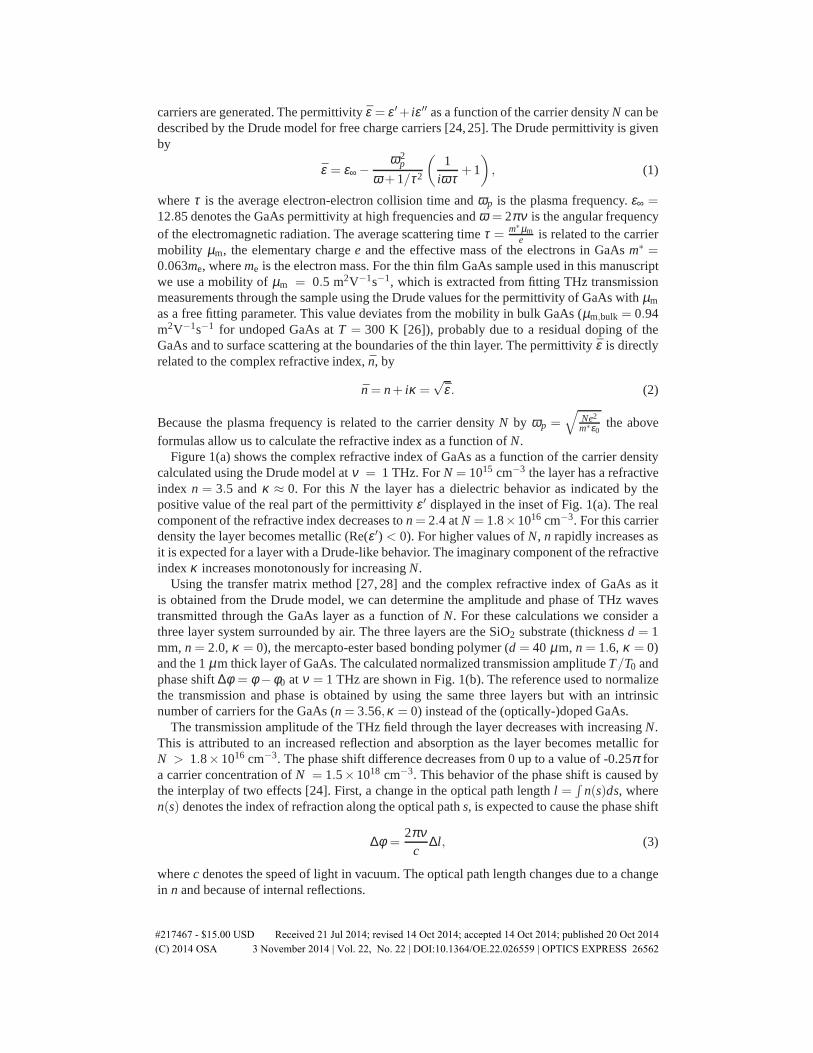
carriers are generated. The permittivityε = ε ′+ iε ′′ as a function of the carrier densityN can bedescribed by the Drude model for free charge carriers [24,25]. The Drude permittivity is givenby
ε = ε∞ −ω2
p
ω +1/τ2
(
1iωτ
+1
)
, (1)
whereτ is the average electron-electron collision time andωp is the plasma frequency.ε∞ =12.85 denotes the GaAs permittivity at high frequencies andω = 2πν is the angular frequencyof the electromagnetic radiation. The average scattering timeτ = m∗µm
e is related to the carriermobility µm, the elementary chargee and the effective mass of the electrons in GaAsm∗ =0.063me, whereme is the electron mass. For the thin film GaAs sample used in this manuscriptwe use a mobility ofµm = 0.5 m2V−1s−1, which is extracted from fitting THz transmissionmeasurements through the sample using the Drude values for the permittivity of GaAs withµm
as a free fitting parameter. This value deviates from the mobility in bulk GaAs (µm,bulk = 0.94m2V−1s−1 for undoped GaAs atT = 300 K [26]), probably due to a residual doping of theGaAs and to surface scattering at the boundaries of the thin layer. The permittivityε is directlyrelated to the complex refractive index, ¯n, by
n = n+ iκ =√
ε . (2)
Because the plasma frequency is related to the carrier densityN by ωp =√
Ne2
m∗ε0the above
formulas allow us to calculate the refractive index as a function ofN.Figure 1(a) shows the complex refractive index of GaAs as a function of the carrier density
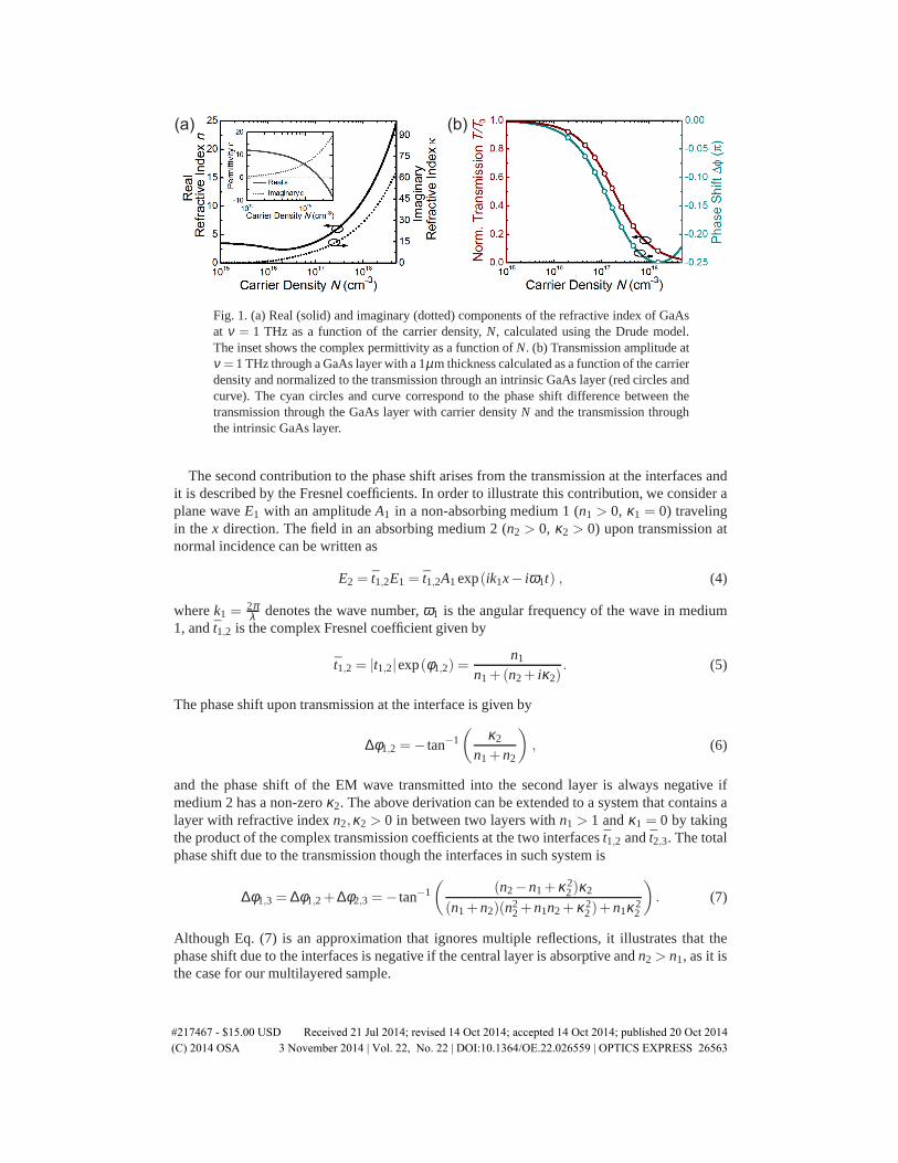
calculated using the Drude model atν = 1 THz. ForN = 1015 cm−3 the layer has a refractiveindex n = 3.5 andκ ≈ 0. For thisN the layer has a dielectric behavior as indicated by thepositive value of the real part of the permittivityε ′ displayed in the inset of Fig. 1(a). The realcomponent of the refractive index decreases ton = 2.4 atN = 1.8×1016 cm−3. For this carrierdensity the layer becomes metallic (Re(ε ′) < 0). For higher values ofN, n rapidly increases asit is expected for a layer with a Drude-like behavior. The imaginary component of the refractiveindexκ increases monotonously for increasingN.
Using the transfer matrix method [27, 28] and the complex refractive index of GaAs as itis obtained from the Drude model, we can determine the amplitude and phase of THz wavestransmitted through the GaAs layer as a function ofN. For these calculations we consider athree layer system surrounded by air. The three layers are the SiO2 substrate (thicknessd = 1mm,n = 2.0, κ = 0), the mercapto-ester based bonding polymer (d = 40 µm, n = 1.6, κ = 0)and the 1µm thick layer of GaAs. The calculated normalized transmission amplitudeT/T0 andphase shift∆φ = φ −φ0 at ν = 1 THz are shown in Fig. 1(b). The reference used to normalizethe transmission and phase is obtained by using the same three layers but with an intrinsicnumber of carriers for the GaAs (n = 3.56,κ = 0) instead of the (optically-)doped GaAs.
The transmission amplitude of the THz field through the layer decreases with increasingN.This is attributed to an increased reflection and absorption as the layer becomes metallic forN > 1.8×1016 cm−3. The phase shift difference decreases from 0 up to a value of -0.25π fora carrier concentration ofN = 1.5×1018 cm−3. This behavior of the phase shift is caused bythe interplay of two effects [24]. First, a change in the optical path lengthl =
∫
n(s)ds, wheren(s) denotes the index of refraction along the optical paths, is expected to cause the phase shift
∆φ =2πν
c∆l, (3)
wherec denotes the speed of light in vacuum. The optical path length changes due to a changein n and because of internal reflections.
#217467 - $15.00 USD Received 21 Jul 2014; revised 14 Oct 2014; accepted 14 Oct 2014; published 20 Oct 2014(C) 2014 OSA 3 November 2014 | Vol. 22, No. 22 | DOI:10.1364/OE.22.026559 | OPTICS EXPRESS 26562
(a) (b)
Fig. 1. (a) Real (solid) and imaginary (dotted) components of the refractive index of GaAsat ν = 1 THz as a function of the carrier density,N, calculated using the Drude model.The inset shows the complex permittivity as a function ofN. (b) Transmission amplitude atν = 1 THz through a GaAs layer with a 1µm thickness calculated as a function of the carrierdensity and normalized to the transmission through an intrinsic GaAs layer (red circles andcurve). The cyan circles and curve correspond to the phase shift difference between thetransmission through the GaAs layer with carrier densityN and the transmission throughthe intrinsic GaAs layer.
The second contribution to the phase shift arises from the transmission at the interfaces andit is described by the Fresnel coefficients. In order to illustrate this contribution, we consider aplane waveE1 with an amplitudeA1 in a non-absorbing medium 1 (n1 > 0, κ1 = 0) travelingin the x direction. The field in an absorbing medium 2 (n2 > 0, κ2 > 0) upon transmission atnormal incidence can be written as
E2 = t1,2E1 = t1,2A1exp(ik1x− iω1t) , (4)
wherek1 =2πλ denotes the wave number,ω1 is the angular frequency of the wave in medium
1, andt1,2 is the complex Fresnel coefficient given by
t1,2 = |t1,2|exp(φ1,2) =n1
n1+(n2+ iκ2). (5)
The phase shift upon transmission at the interface is given by
∆φ1,2 =− tan−1(
κ2
n1+ n2
)
, (6)
and the phase shift of the EM wave transmitted into the second layer is always negative ifmedium 2 has a non-zeroκ2. The above derivation can be extended to a system that contains alayer with refractive indexn2,κ2 > 0 in between two layers withn1 > 1 andκ1 = 0 by takingthe product of the complex transmission coefficients at the two interfacest1,2 andt2,3. The totalphase shift due to the transmission though the interfaces in such system is
∆φ1,3 = ∆φ1,2+∆φ2,3 =− tan−1(
(n2− n1+κ22)κ2
(n1+ n2)(n22+ n1n2+κ2
2)+ n1κ22
)
. (7)
Although Eq. (7) is an approximation that ignores multiple reflections, it illustrates that thephase shift due to the interfaces is negative if the central layer is absorptive andn2 > n1, as it isthe case for our multilayered sample.
#217467 - $15.00 USD Received 21 Jul 2014; revised 14 Oct 2014; accepted 14 Oct 2014; published 20 Oct 2014(C) 2014 OSA 3 November 2014 | Vol. 22, No. 22 | DOI:10.1364/OE.22.026559 | OPTICS EXPRESS 26563
(a) (b)
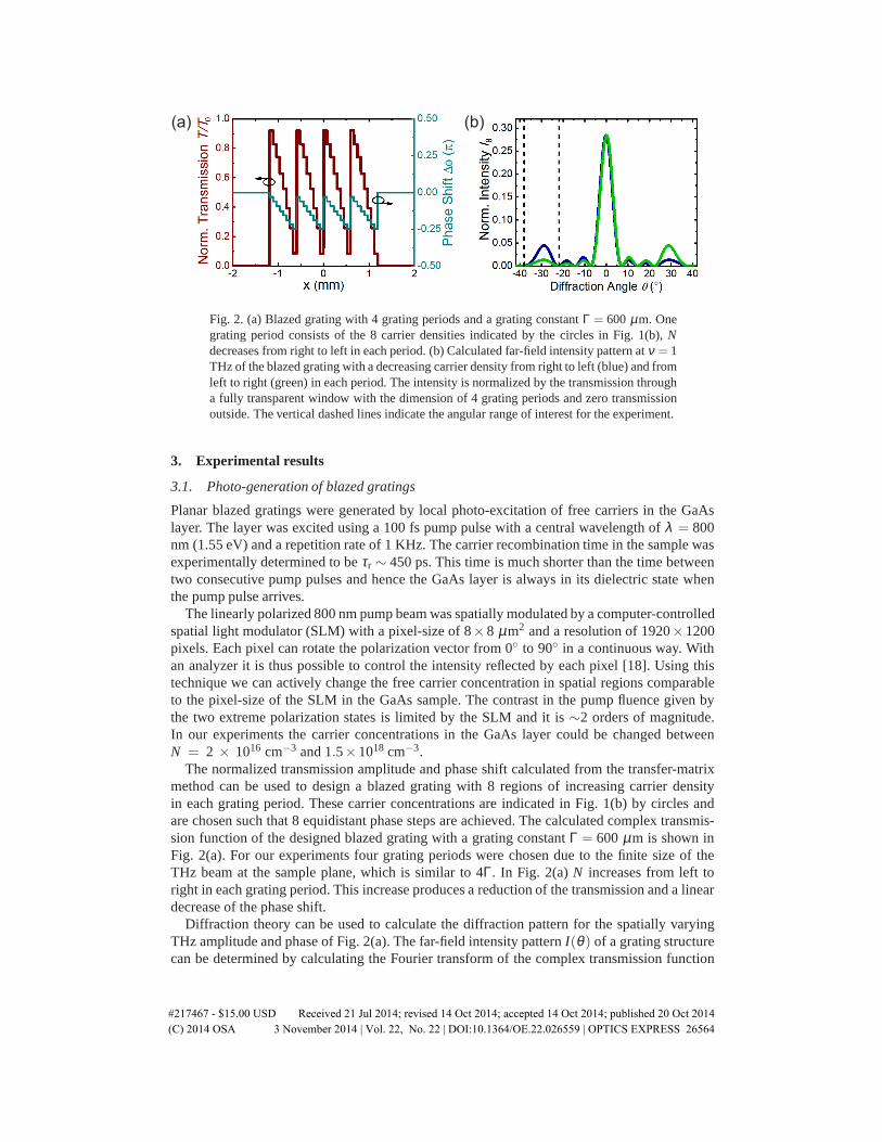
Fig. 2. (a) Blazed grating with 4 grating periods and a grating constantΓ = 600 µm. Onegrating period consists of the 8 carrier densities indicated by the circles in Fig. 1(b),Ndecreases from right to left in each period. (b) Calculated far-field intensity pattern atν = 1THz of the blazed grating with a decreasing carrier density from right to left (blue) and fromleft to right (green) in each period. The intensity is normalized by the transmission througha fully transparent window with the dimension of 4 grating periods and zero transmissionoutside. The vertical dashed lines indicate the angular range of interest for the experiment.
3. Experimental results
3.1. Photo-generation of blazed gratings
Planar blazed gratings were generated by local photo-excitation of free carriers in the GaAslayer. The layer was excited using a 100 fs pump pulse with a central wavelength ofλ = 800nm (1.55 eV) and a repetition rate of 1 KHz. The carrier recombination time in the sample wasexperimentally determined to beτr ∼ 450 ps. This time is much shorter than the time betweentwo consecutive pump pulses and hence the GaAs layer is always in its dielectric state whenthe pump pulse arrives.
The linearly polarized 800 nm pump beam was spatially modulated by a computer-controlledspatial light modulator (SLM) with a pixel-size of 8×8 µm2 and a resolution of 1920×1200pixels. Each pixel can rotate the polarization vector from 0◦ to 90◦ in a continuous way. Withan analyzer it is thus possible to control the intensity reflected by each pixel [18]. Using thistechnique we can actively change the free carrier concentration in spatial regions comparableto the pixel-size of the SLM in the GaAs sample. The contrast in the pump fluence given bythe two extreme polarization states is limited by the SLM and it is∼2 orders of magnitude.In our experiments the carrier concentrations in the GaAs layer could be changed betweenN = 2 × 1016 cm−3 and 1.5×1018 cm−3.
The normalized transmission amplitude and phase shift calculated from the transfer-matrixmethod can be used to design a blazed grating with 8 regions of increasing carrier densityin each grating period. These carrier concentrations are indicated in Fig. 1(b) by circles andare chosen such that 8 equidistant phase steps are achieved. The calculated complex transmis-sion function of the designed blazed grating with a grating constantΓ = 600 µm is shown inFig. 2(a). For our experiments four grating periods were chosen due to the finite size of theTHz beam at the sample plane, which is similar to 4Γ. In Fig. 2(a)N increases from left toright in each grating period. This increase produces a reduction of the transmission and a lineardecrease of the phase shift.
Diffraction theory can be used to calculate the diffraction pattern for the spatially varyingTHz amplitude and phase of Fig. 2(a). The far-field intensity patternI(θ ) of a grating structurecan be determined by calculating the Fourier transform of the complex transmission function
#217467 - $15.00 USD Received 21 Jul 2014; revised 14 Oct 2014; accepted 14 Oct 2014; published 20 Oct 2014(C) 2014 OSA 3 November 2014 | Vol. 22, No. 22 | DOI:10.1364/OE.22.026559 | OPTICS EXPRESS 26564

T (x) of the structure that causes the diffraction
I(θ ) = F[T (x)]2 = F [T (x) ·exp(iφ(x))]2 . (8)
The blue curve in Fig. 2(b) shows the far field intensity patternIθ of the blazed gratingcalculated using Eq. (8). The green curve is the far-field intensity pattern of the complementarygrating, i.e., a blazed grating with the same grating constant andN decreasing from left to rightfor each grating period. Besides the central peak, which represents the zeroth order diffraction,the +1 and -1 diffracted orders at 30◦ and−30◦ are visible. The linear change of phase shiftproduces a pronounced asymmetry in the intensity between these orders.
Diffraction theory predicts that the beam steering efficiency depends on three factors. First,the phase shift∆φ(x) achieved in each grating period. When the phase shift is less than 2πthere is light scattered into other diffraction orders and the beam steering efficiency decreases.Second, the transmission amplitudeT (x) throughout the grating. If this is less than unity thereis light absorbed or reflected by the grating structure and hence the efficiency of the gratingdecreases. Third, the number of grating periods in the structure. The grating orders are sharperwhen the grating consists of a larger number of grating periods. The small amount of periods inthe grating shown in Fig. 2(a), together with the reduction in the transmission and the limitedphase shift, are the reasons for the relatively small change of the diffracted intensities dependingon the blazing. In Section 3.3 we describe other structures that can significantly improve thesteering efficiency.
3.2. THz diffraction measurements
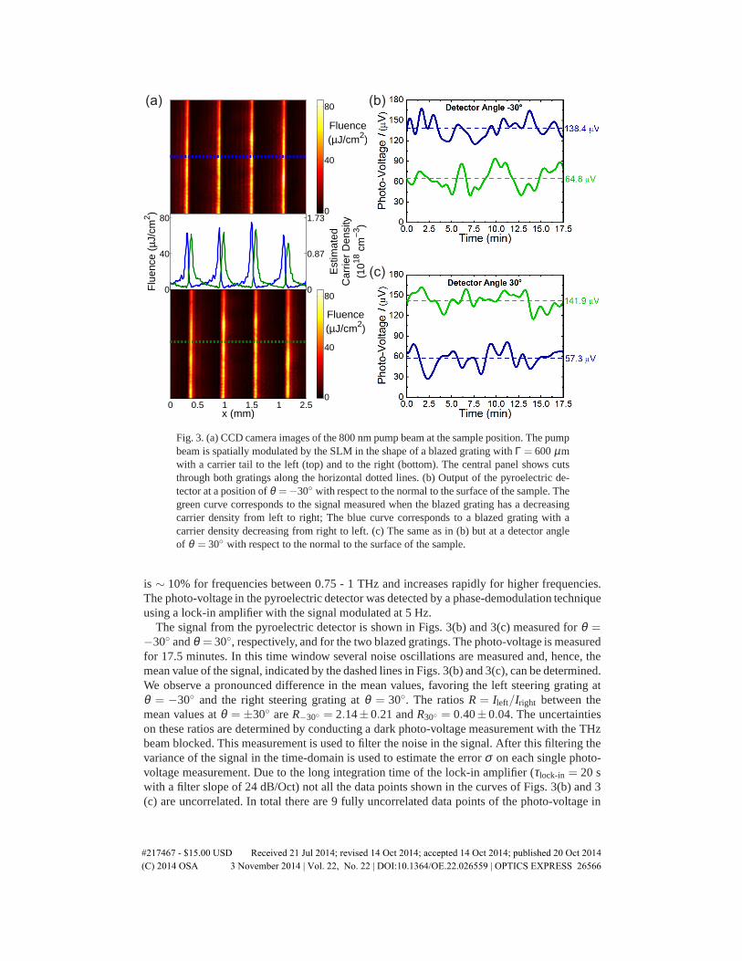
Figure 3(a) shows images of the blazed gratings photo-generated in our setup using the SLM.These images were taken by replacing the GaAs sample in the setup by a CCD camera. Thecolor scale represents the illumination fluence. The upper panel displays the grating with carrierdensityN increasing in each period from left to right, while the lower panel corresponds to thegrating with decreasingN. Cuts through the images along the horizontal dashed lines are shownin the central panel of Fig. 3(a) by the blue and green curves for the increasing and decreasingN, respectively. The right axis in this panel is the estimated photo-generated carrier densityobtained from the illumination fluence.
In order to measure the beam steering by the photo-generated blazed gratings we used THzpulses generated by a THz time-domain spectrometer (THz-TDS) [18]. These pulses probedthe photo-generated grating at a time delay with the optical pulse of 10 ps<< τr. The intensityspectrum of the THz pulse is shown in Fig. 4. The carrier diffusion length in the sample overthis time window is∼140 nm [29]. This is much shorter than the characteristic length scale inthe experiment, i.e. the pixel-size of the SLM. The THz pulse is weakly focussed at the sampleposition with a full width half maximum (FWHM) of≈ 2.5 mm.
Since the configuration of the THz-TDS was quite rigid and designed to measure only thezeroth-order transmission (θ = 0◦), we used a pyroelectric detector to detect the diffracted or-ders of the photo-generated blazed gratings. In order to enhance the signal-to-noise ratio, aWinston cone was placed in front of the detector to collect the radiation over a larger solid an-gle of 0.56 sr. The Winston cone is very sensitive to the angle of incidence, e.g. for an angle ofincidence that deviates 4◦ from its axis the detected signal by the detector is reduced by a factorof 2. Therefore, the cone is also used as a spatial filter to reduce the scattered THz radiation de-tected by the pyroelectric detector at angles other than the diffraction angle. In the experimentsthe pyroelectric detector was placed at a distance of 72 mm behind the sample atθ = −30◦
and 30◦ with respect to the normal of the sample surface. The pyroelectric detector could beonly used for relative intensity measurements because there is no calibration available for theabsorption efficiency of the device at frequencies below 0.75 THz. This absorption efficiency
#217467 - $15.00 USD Received 21 Jul 2014; revised 14 Oct 2014; accepted 14 Oct 2014; published 20 Oct 2014(C) 2014 OSA 3 November 2014 | Vol. 22, No. 22 | DOI:10.1364/OE.22.026559 | OPTICS EXPRESS 26565
Fluence(µJ/cm2)
0
40
80
x (mm)
0 0.5 1 1.5 1 2.5
Fluence(µJ/cm2)
0
40
800
40
80
Flu
ence
(µJ
/cm
2 )
0
0.87
1.73
Est
imat
edC
arrie
r D
ensi
ty(1
018 c
m−3
)
(a)
(c)
(b)
Fig. 3. (a) CCD camera images of the 800 nm pump beam at the sample position. The pumpbeam is spatially modulated by the SLM in the shape of a blazed grating withΓ = 600µmwith a carrier tail to the left (top) and to the right (bottom). The central panel shows cutsthrough both gratings along the horizontal dotted lines. (b) Output of the pyroelectric de-tector at a position ofθ =−30◦ with respect to the normal to the surface of the sample. Thegreen curve corresponds to the signal measured when the blazed grating has a decreasingcarrier density from left to right; The blue curve corresponds to a blazed grating with acarrier density decreasing from right to left. (c) The same as in (b) but at a detector angleof θ = 30◦ with respect to the normal to the surface of the sample.
is ∼ 10% for frequencies between 0.75 - 1 THz and increases rapidly for higher frequencies.The photo-voltage in the pyroelectric detector was detected by a phase-demodulation techniqueusing a lock-in amplifier with the signal modulated at 5 Hz.
The signal from the pyroelectric detector is shown in Figs. 3(b) and 3(c) measured forθ =−30◦ andθ = 30◦, respectively, and for the two blazed gratings. The photo-voltage is measuredfor 17.5 minutes. In this time window several noise oscillations are measured and, hence, themean value of the signal, indicated by the dashed lines in Figs. 3(b) and 3(c), can be determined.We observe a pronounced difference in the mean values, favoring the left steering grating atθ = −30◦ and the right steering grating atθ = 30◦. The ratiosR = Ileft/Iright between themean values atθ = ±30◦ areR−30◦ = 2.14±0.21 andR30◦ = 0.40±0.04. The uncertaintieson these ratios are determined by conducting a dark photo-voltage measurement with the THzbeam blocked. This measurement is used to filter the noise in the signal. After this filtering thevariance of the signal in the time-domain is used to estimate the errorσ on each single photo-voltage measurement. Due to the long integration time of the lock-in amplifier (τlock-in = 20 swith a filter slope of 24 dB/Oct) not all the data points shown in the curves of Figs. 3(b) and 3(c) are uncorrelated. In total there are 9 fully uncorrelated data points of the photo-voltage in
#217467 - $15.00 USD Received 21 Jul 2014; revised 14 Oct 2014; accepted 14 Oct 2014; published 20 Oct 2014(C) 2014 OSA 3 November 2014 | Vol. 22, No. 22 | DOI:10.1364/OE.22.026559 | OPTICS EXPRESS 26566

0.5 1.0 1.5 2.0 2.5 3.0 3.5 4.0
10-6
10-5
10-4
10-3
10-2
10-1
100
N
orm
aliz
ed In
tens
ity
Frequency (THz)
Fig. 4. Intensity spectrum of the THz probe pulse. The maximum intensity is normalizedto 1.
each data set. We can treat these measurements as independent, all with an errorσ . From thiswe can determine the standard error on the mean value ofI, which is given byσE = σ√
9. The
errors onR are calculated through standard error-propagation.To further investigate the beam steering properties of the blazed gratings, a new set of
measurements was conducted in which the pyroelectric detector was kept fixed atθ = −30◦.The photo-voltage was measured for 19 left and right steering gratings with 3 periods and grat-ing constants varying betweenΓ = 391 and 1174µm. The 3 grating periods forΓ = 800 µmcorrespond to a length similar to the FWHM of the THz beam. For each measurement the meanvalue was extracted and the ratio between the mean values of the left and right steering gratingswas calculated. The results are shown in Fig. 5. The experimental data show a maximum in theintensity ratioR−30◦ and an optimum in the steering peak forΓ = 600µm.
The black curve in Fig. 5 is calculated using diffraction theory for the different grating con-stants. The diffracted intensity for each grating was calculated in an interval of±8◦ around
400 600 800 1000 1200
1.25
1.50
1.75
2.00
2.25
Rat
io R
-30°
= I l
eft /
I rig
ht
Grating Constant ( m)
Fig. 5. Ratio between the diffracted THz intensities by the left and the right steering blazedgratings measured atθ = −30◦ for 19 different grating constants. The blue squares aremeasurements and the black curve are calculations using diffraction theory.
#217467 - $15.00 USD Received 21 Jul 2014; revised 14 Oct 2014; accepted 14 Oct 2014; published 20 Oct 2014(C) 2014 OSA 3 November 2014 | Vol. 22, No. 22 | DOI:10.1364/OE.22.026559 | OPTICS EXPRESS 26567
30◦ and−30◦ and weighted by the angular response of the Winston cone [34], the frequencyresponsivity of the pyroelectric detector [35], and the spectrum of the generated THz radiation.The ratio between the calculated intensities at 30◦ and−30◦ was determined considering thethree grating periods for eachΓ. The simple diffraction model describes reasonably well quali-tatively and quantitatively the measurements within the error bars. Therefore, we apply it in thenext section to explore further possibilities to improve the steering efficiency.
3.3. Maximization of the beam steering
The beam steering efficiency can be increased by using a layer of semiconductor that induces alarger phase shift in the transmitted THz radiation. To investigate the effect of the semiconduc-tor material on the steering efficiency, we have calculated the phase shift at 1 THz induced bya layer with a thickness of 1µm and arbitrary values ofn andk. The results are depicted in thecontour plot of Fig. 6(a) in which the color scale indicates the phase shift∆φair = φ −φair withrespect to a similar layer of air.
Superimposed to the color plot in Fig. 6(a) are three curves corresponding to the complexrefractive index of GaAs, silicon (Si) and indium antimonide (InSb) for different carrier con-centrations. The various ranges ofN are illustrated by the different colors forming each curve(see the legend of the figure). These curves are calculated using the Drude model (Eqs. (1)-(2)).For Si we usem∗ = 0.98me, ε∞ = 11.7 and [30]
µm,Si=1
1000
[
52.2+1364.8
1+(N/(1.295×1017))0.891 −
43.4
1+(3.43×10²⁰/N)2
]
m2V−1s−1,
while for InSb we usem∗ = 0.0153me, ε∞ = 15.68 and [31]
µm,InSb=18.03
1+(N/(3×1017)0.68)m2V−1s−1.
In the case of InSb, we consider a temperature of 200 K. At this temperature the intrinsiccarrier concentration is∼7×1014 cm−3, leading to dielectric behavior at the THz frequenciesof interest [32,33]. Figure 6(b) shows the calculated phase shift as a function ofN, hence theseare cuts along the(n,κ)-curves of Fig. 6(a). Within the carrier concentration range that we canreach with our experimental setup, InSb induces the largest phase shift on the transmitted THzradiation. The normalized transmission amplitude is displayed in Fig. 6(c) as a function ofN.The semiconducting layers become opaque asN increases and the layer transits from dielectricto metallic behavior. From Fig. 6 we expect that using an InSb layer will increase the beamsteering efficiency.
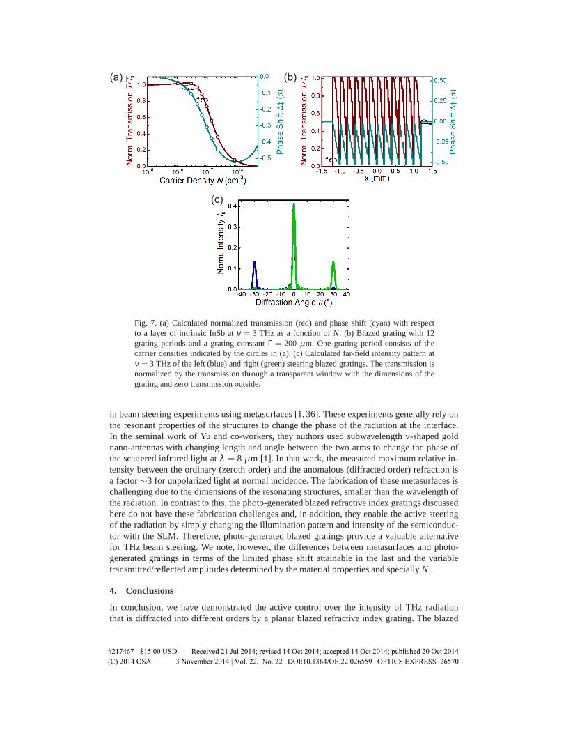
As we show next, using THz radiation with a higher frequency will improve significantly thebeam steering efficiency. Figure 7 illustrates the calculation of beam steering using the Drudemodel, transfer-matrix method and diffraction theory for EM radiation atν = 3 THz and a 1µm thick layer of InSb. Figure 7(a) shows the calculated normalized transmission amplitudeT/T0 and phase shift∆φ with respect to intrinsic InSb as a function of the carrier density. Thetransmission amplitude initially shows a slight increase for increasingN. This is due to a smalldecrease of the real part of the refractive indexn for theseN. ForN larger than 2.8×1016 cm−3
the sample becomes metallic and the transmission amplitude decreases. The phase shift curveis shifted to largerN with respect to the case of 1 THz and a larger∆φ can be achieved due tothe frequency dependence of Eq. (3).
Figure 7(b) shows a blazed grating design with the values ofN indicated by the open circlesof Fig. 7(a). As in the case of GaAs, this range of values can be achieved through illuminationof the sample with a SLM. Atν = 3 THz the grating constantΓ must be 3 times shorter than
#217467 - $15.00 USD Received 21 Jul 2014; revised 14 Oct 2014; accepted 14 Oct 2014; published 20 Oct 2014(C) 2014 OSA 3 November 2014 | Vol. 22, No. 22 | DOI:10.1364/OE.22.026559 | OPTICS EXPRESS 26568

(a)
(c)(b)
Fig. 6. (a) Phase shift difference (colorscale) between a transmitted wave of frequencyν =1 THz through a 1µm thick layer with complex index of refraction given by the axis and atransmitted wave through a layer of air of equal thickness. The (n,κ)-curves for GaAs, InSband Si are calculated using the Drude model and plotted with the solid curves. Differentcarrier concentration ranges are indicated with different colors as described by the legend.(b) Phase shift with respect to a layer of air as a function of the carrier concentration througha 1 µm layer of GaAs (blue), InSb (green) and Si (red) atν = 1 THz. (c) Normalizedtransmission amplitude with respect to air as a function of the carrier concentration througha 1µm layer of GaAs (blue), InSb (green) and Si (red) atν = 1 THz.
for ν = 1 THz to obtain the first diffraction order at the same angle. Because of this reductionin Γ, it is possible to increase the number of periods that fit within the size of the THz beam.Hence, we use 12 grating periods withΓ = 200µm to calculate the diffraction pattern. Fouriertransforming the complex transmission function using Eq. (8) results in Fig. 7(c). Because ofthe larger number of grating periods, the diffracted orders are much narrower than the onescalculated for 1 THz in Fig. 1. Also, because of the larger phase shift induced by each gratingperiod on the THz radiation, the beam steering efficiency increases. Integration of the intensityover the diffraction orders gives more than one order of magnitude asymmetry between the +1and -1 diffracted orders. The calculated intensity ratios between the +1 and -1 order are in thiscaseR-30 = 13.85 andR30= 0.07.
The calculated difference between the zeroth and first orders is similar to that demonstrated
#217467 - $15.00 USD Received 21 Jul 2014; revised 14 Oct 2014; accepted 14 Oct 2014; published 20 Oct 2014(C) 2014 OSA 3 November 2014 | Vol. 22, No. 22 | DOI:10.1364/OE.22.026559 | OPTICS EXPRESS 26569
(a)
(c)
(b)(a)
Fig. 7. (a) Calculated normalized transmission (red) and phase shift (cyan) with respectto a layer of intrinsic InSb atν = 3 THz as a function ofN. (b) Blazed grating with 12grating periods and a grating constantΓ = 200 µm. One grating period consists of thecarrier densities indicated by the circles in (a). (c) Calculated far-field intensity pattern atν = 3 THz of the left (blue) and right (green) steering blazed gratings. The transmission isnormalized by the transmission through a transparent window with the dimensions of thegrating and zero transmission outside.
in beam steering experiments using metasurfaces [1, 36]. These experiments generally rely onthe resonant properties of the structures to change the phase of the radiation at the interface.In the seminal work of Yu and co-workers, they authors used subwavelength v-shaped goldnano-antennas with changing length and angle between the two arms to change the phase ofthe scattered infrared light atλ = 8 µm [1]. In that work, the measured maximum relative in-tensity between the ordinary (zeroth order) and the anomalous (diffracted order) refraction isa factor∼3 for unpolarized light at normal incidence. The fabrication of these metasurfaces ischallenging due to the dimensions of the resonating structures, smaller than the wavelength ofthe radiation. In contrast to this, the photo-generated blazed refractive index gratings discussedhere do not have these fabrication challenges and, in addition, they enable the active steeringof the radiation by simply changing the illumination pattern and intensity of the semiconduc-tor with the SLM. Therefore, photo-generated blazed gratings provide a valuable alternativefor THz beam steering. We note, however, the differences between metasurfaces and photo-generated gratings in terms of the limited phase shift attainable in the last and the variabletransmitted/reflected amplitudes determined by the material properties and speciallyN.
4. Conclusions
In conclusion, we have demonstrated the active control over the intensity of THz radiationthat is diffracted into different orders by a planar blazed refractive index grating. The blazed
#217467 - $15.00 USD Received 21 Jul 2014; revised 14 Oct 2014; accepted 14 Oct 2014; published 20 Oct 2014(C) 2014 OSA 3 November 2014 | Vol. 22, No. 22 | DOI:10.1364/OE.22.026559 | OPTICS EXPRESS 26570
profile was achieved by photo-exciting free charge carriers in a thin layer of GaAs using acomputer-controlled spatial light modulator. The measurements are explained using diffractiontheory and considering a constant gradient of phase discontinuity along the interface. Photo-induced blazed gratings are planar structures that enable beam steering without the need ofresonant subwavelength structures as in the case of metasurfaces. Ratios of intensities betweenthe +1 and -1 diffracted orders of more than one order of magnitude can be achieved using highmobility semiconductors such as InSb.
Acknowledgments
The authors would like to acknowledge P. Mulder, G. J. Bauhuis and J. J. Schermer for thesample fabrication. This work has been supported by the ERC through grant no 259727 THZ-PLASMON and by the Netherlands Foundation for Fundamental Research on Matter (FOM)and the Netherlands Organization for Scientific Research (NWO).
#217467 - $15.00 USD Received 21 Jul 2014; revised 14 Oct 2014; accepted 14 Oct 2014; published 20 Oct 2014(C) 2014 OSA 3 November 2014 | Vol. 22, No. 22 | DOI:10.1364/OE.22.026559 | OPTICS EXPRESS 26571