Embed Size (px)
Citation preview

Active Microwave Remote Sensing
Lecture 11Oct 5, 2005
Reading materials: Chapter 9
Basics of passive and active RS
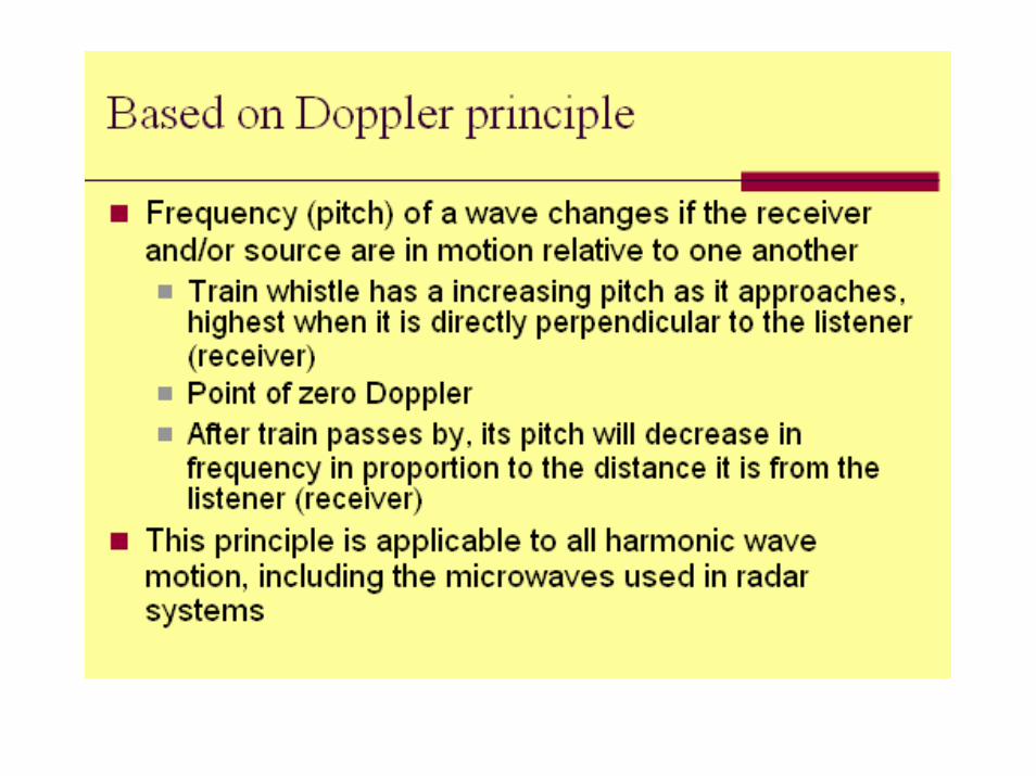
Passive: uses natural energy, either reflected sunlight (solar energy) or emitted thermal or microwave radiation.
Active: sensor creates its own energyTransmitted toward Earth or other targetsInteracts with atmosphere and/or surfaceReflects back toward sensor (backscatter)
Widely used active RS systemsRADAR: RAdio Detection And Ranging (read p285 for an explanation)
Long-wavelength microwaves (1 – 100 cm)
LIDAR: LIght Detection And RangingShort-wavelength laser light (UV, visible, near IR)
SONAR: SOund Navigation And RangingSound waves through a water column.Sound waves are extremely slow (300 m/s in air, 1,530 m/s in sea-water)Bathymetric sonar (measure water depths and changes in bottom topography )Imaging sonar or sidescan imaging sonar (imaging the bottom topography and bottom roughness)
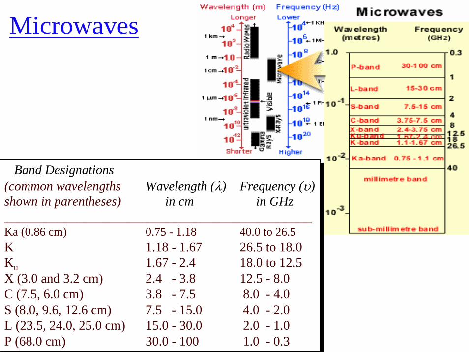
Microwaves
Band Designations(common wavelengths Wavelength (λ) Frequency (υ)shown in parentheses) in cm in GHz_______________________________________________Ka (0.86 cm) 0.75 - 1.18 40.0 to 26.5K 1.18 - 1.67 26.5 to 18.0Ku 1.67 - 2.4 18.0 to 12.5X (3.0 and 3.2 cm) 2.4 - 3.8 12.5 - 8.0C (7.5, 6.0 cm) 3.8 - 7.5 8.0 - 4.0S (8.0, 9.6, 12.6 cm) 7.5 - 15.0 4.0 - 2.0L (23.5, 24.0, 25.0 cm) 15.0 - 30.0 2.0 - 1.0P (68.0 cm) 30.0 - 100 1.0 - 0.3
Band Designations(common wavelengths Wavelength (λ) Frequency (υ)shown in parentheses) in cm in GHz_______________________________________________Ka (0.86 cm) 0.75 - 1.18 40.0 to 26.5K 1.18 - 1.67 26.5 to 18.0Ku 1.67 - 2.4 18.0 to 12.5X (3.0 and 3.2 cm) 2.4 - 3.8 12.5 - 8.0C (7.5, 6.0 cm) 3.8 - 7.5 8.0 - 4.0S (8.0, 9.6, 12.6 cm) 7.5 - 15.0 4.0 - 2.0L (23.5, 24.0, 25.0 cm) 15.0 - 30.0 2.0 - 1.0P (68.0 cm) 30.0 - 100 1.0 - 0.3
Two active radar imaging systems
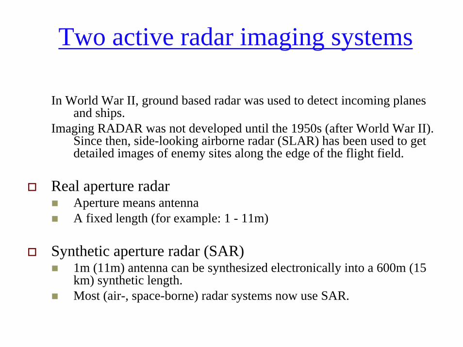
In World War II, ground based radar was used to detect incoming planes and ships.
Imaging RADAR was not developed until the 1950s (after World War II). Since then, side-looking airborne radar (SLAR) has been used to get detailed images of enemy sites along the edge of the flight field.
Real aperture radarAperture means antennaA fixed length (for example: 1 - 11m)
Synthetic aperture radar (SAR)1m (11m) antenna can be synthesized electronically into a 600m (15 km) synthetic length.Most (air-, space-borne) radar systems now use SAR.
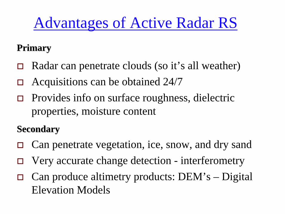
Advantages of Active Radar RS PrimaryPrimary
Radar can penetrate clouds (so it’s all weather)Acquisitions can be obtained 24/7 Provides info on surface roughness, dielectric properties, moisture content
SecondarySecondary
Can penetrate vegetation, ice, snow, and dry sandVery accurate change detection - interferometryCan produce altimetry products: DEM’s – Digital Elevation Models
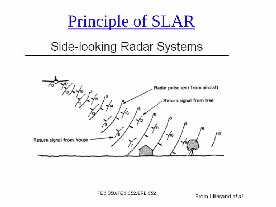
Principle of SLAR
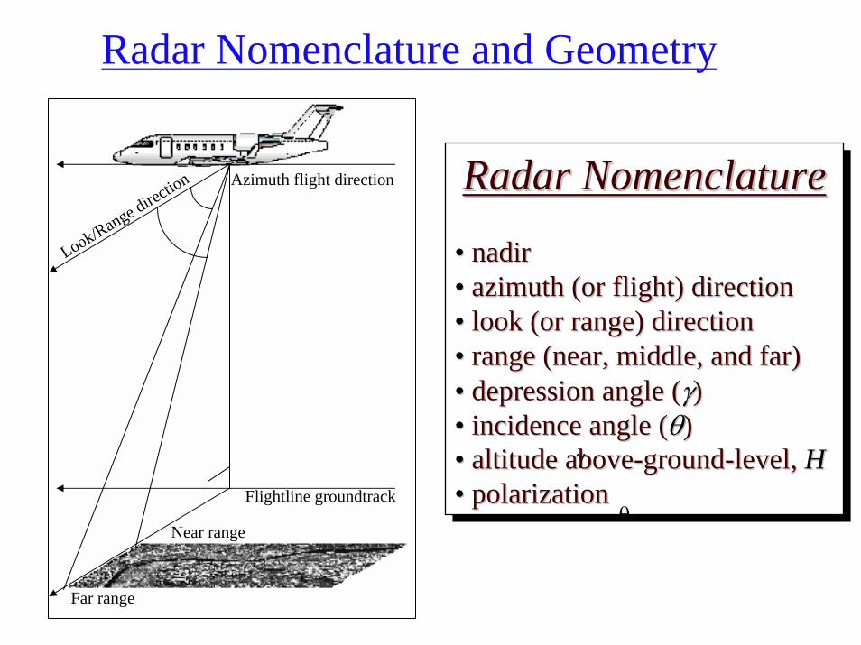
Radar Nomenclature and Geometry
Azimuth flight direction
Flightline groundtrack
Look/Range direction
Far range
Near range
Radar Nomenclature
• nadir• azimuth (or flight) direction• look (or range) direction• range (near, middle, and far)• depression angle (γ)• incidence angle (θ)• altitude above-ground-level, H• polarization
Radar NomenclatureRadar Nomenclature
• • nadirnadir•• azimuth (or flight) directionazimuth (or flight) direction•• look (or range) directionlook (or range) direction•• range (near, middle, and far)range (near, middle, and far)•• depression angle (depression angle (γγ))•• incidence angle (incidence angle (θθ))•• altitude abovealtitude above--groundground--level, level, HH•• polarizationpolarization
θ
γ
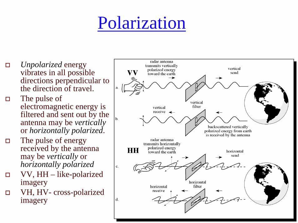
Polarization
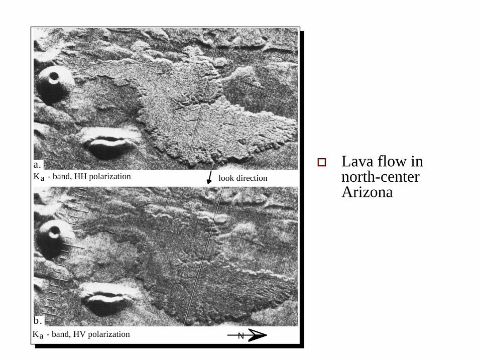
Unpolarized energy vibrates in all possible directions perpendicular to the direction of travel. The pulse of electromagnetic energy is filtered and sent out by the antenna may be vertically or horizontally polarized. The pulse of energy received by the antenna may be vertically orhorizontally polarizedVV, HH – like-polarized imageryVH, HV- cross-polarized imagery
a.
b.
look direction
N
Ka - band, HH polarization
Ka - band, HV polarization
Lava flow in north-center Arizona

Slant-range vs. Ground-range geometry
Radar imagery has a different geometry than that produced by most conventional remote sensor systems, such as cameras, multispectral scanners or area-array detectors. Therefore, one must be very careful when attempting to make radargrammetric measurements.
• Uncorrected radar imagery is displayed in what is called slant-range geometry, i.e., it is based on the actual distance from the radar to each of the respective features in the scene.
• It is possible to convert the slant-range display into the true ground-range display on the x-axis so that features in the scene are in their proper planimetric (x,y) position relative to one another in the final radar image.

Most radar systems and data providers now provide the data in ground-range geometry
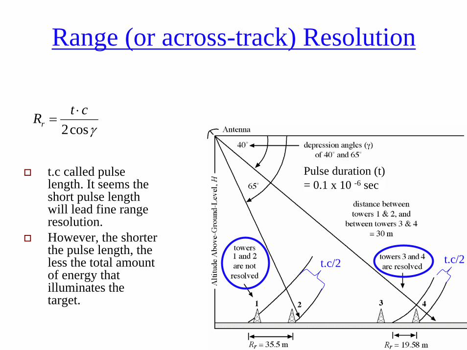
Range (or across-track) Resolution
γcos2ctRr⋅
=
Pulse duration (t)= 0.1 x 10 -6 sec
t.c called pulse length. It seems the short pulse length will lead fine range resolution. However, the shorter the pulse length, the less the total amount of energy that illuminates the target.
t.c/2 t.c/2
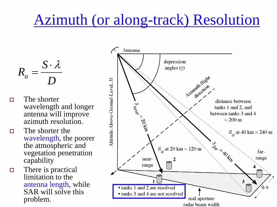
Azimuth (or along-track) Resolution
DSRaλ⋅
=
The shorter wavelength and longer antenna will improve azimuth resolution. The shorter the wavelength, the poorer the atmospheric and vegetation penetration capabilityThere is practical limitation to the antenna length, while SAR will solve this problem.
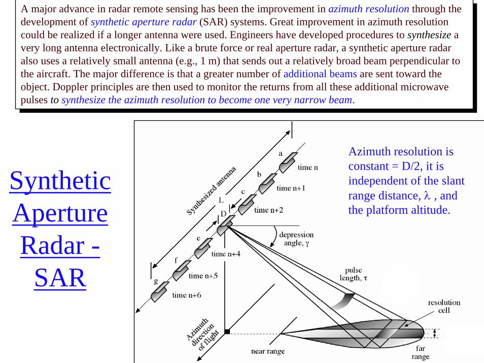
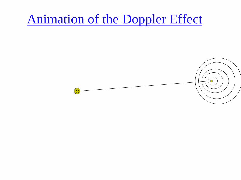
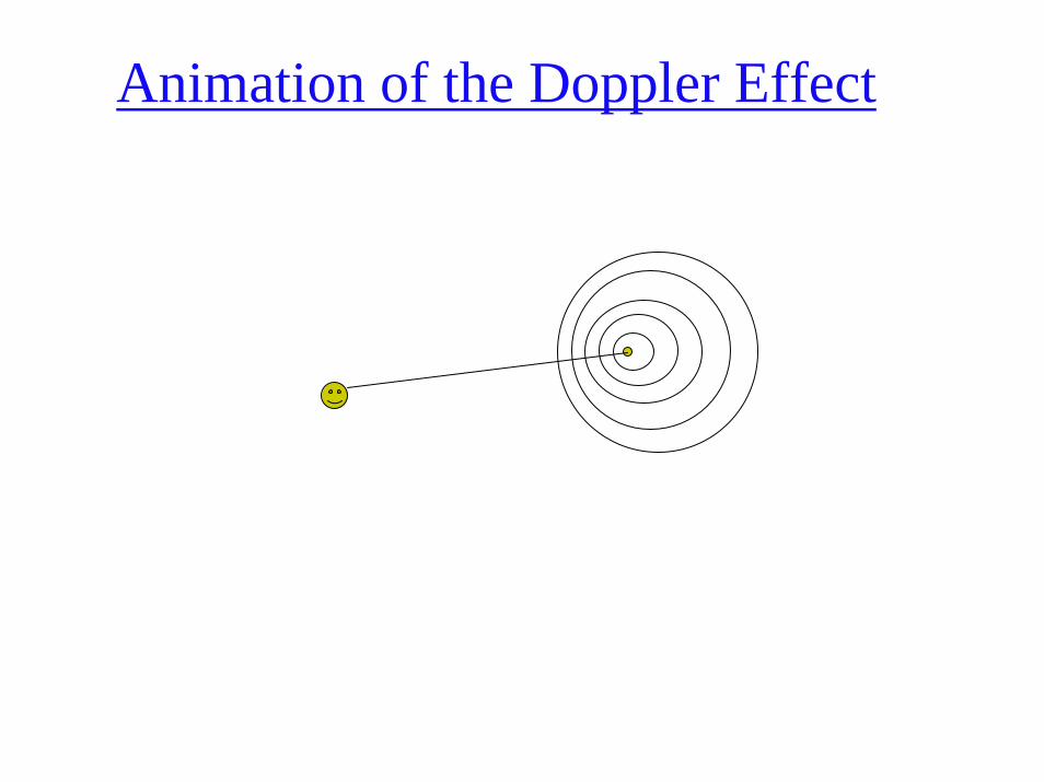
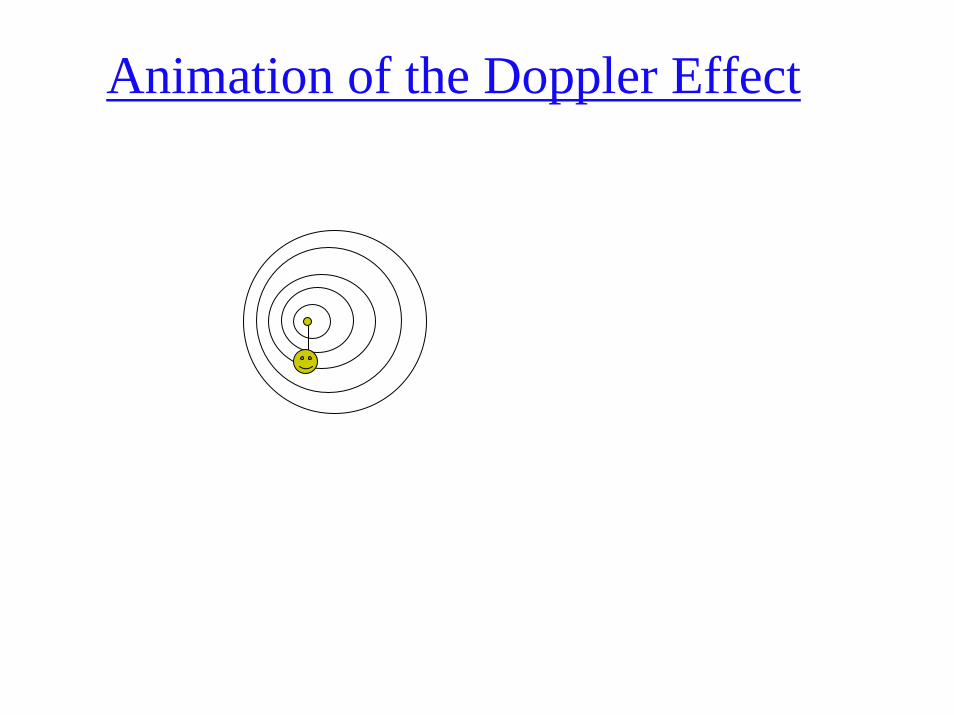
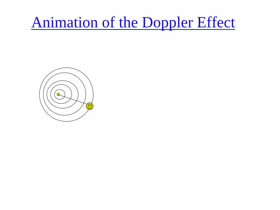
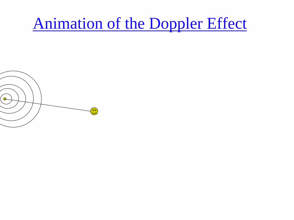
A major advance in radar remote sensing has been the improvement in azimuth resolution through the development of synthetic aperture radar (SAR) systems. Great improvement in azimuth resolution could be realized if a longer antenna were used. Engineers have developed procedures to synthesize a very long antenna electronically. Like a brute force or real aperture radar, a synthetic aperture radar also uses a relatively small antenna (e.g., 1 m) that sends out a relatively broad beam perpendicular to the aircraft. The major difference is that a greater number of additional beams are sent toward the object. Doppler principles are then used to monitor the returns from all these additional microwave pulses to synthesize the azimuth resolution to become one very narrow beam.
A major advance in radar remote sensing has been the improvement in azimuth resolution through the development of synthetic aperture radar (SAR) systems. Great improvement in azimuth resolution could be realized if a longer antenna were used. Engineers have developed procedures to synthesize a very long antenna electronically. Like a brute force or real aperture radar, a synthetic aperture radar also uses a relatively small antenna (e.g., 1 m) that sends out a relatively broad beam perpendicular to the aircraft. The major difference is that a greater number of additional beams are sent toward the object. Doppler principles are then used to monitor the returns from all these additional microwave pulses to synthesize the azimuth resolution to become one very narrow beam.
Azimuth resolution isconstant = D/2, it isindependent of the slantrange distance, λ , andthe platform altitude.
Synthetic Aperture Radar -
SAR
Animation of the Doppler Effect
Animation of the Doppler Effect
Animation of the Doppler Effect

Animation of the Doppler Effect
Animation of the Doppler Effect
Animation of the Doppler Effect
Animation of the Doppler Effect

Animation of the Doppler Effect
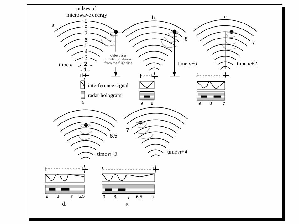
9 8 7 6 5 4 3 2 1
time n
time n+4time n+3
time n+2
pulses of microwave energy
interference signal
radar hologram
a.b. c.
d. e.
8 7
6.5 7
9 9 8 9 8 7
78 9 78 9 6.5 6.5 7
time n+1object is a
constant distance from the flightline
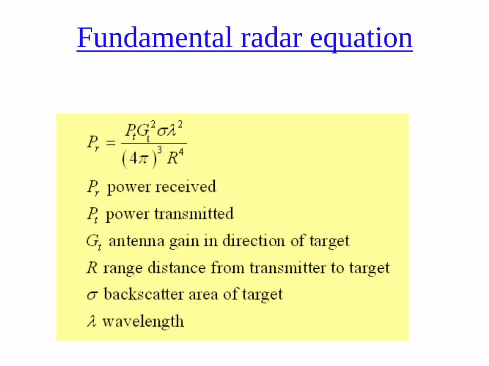
Fundamental radar equation
t
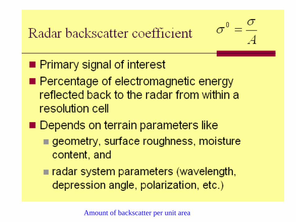
Amount of backscatter per unit area
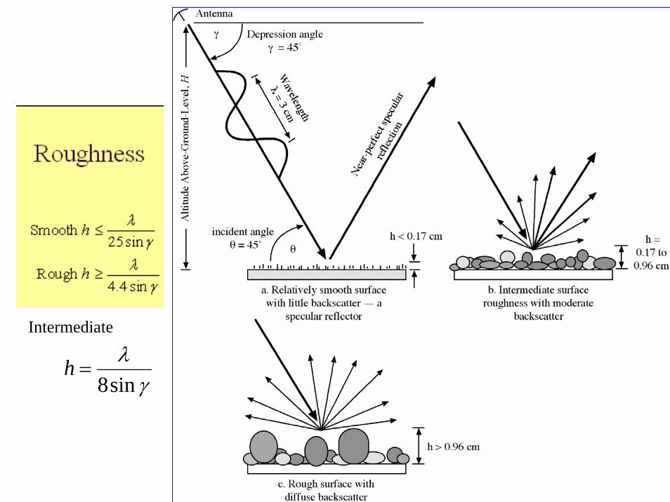
γλ
sin8=h
Intermediate
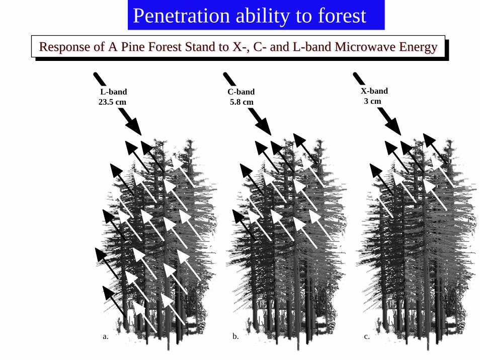
Penetration ability to forest
L-band 23.5 cm
C-band 5.8 cm
X-band 3 cm
a. b. c.
Response of A Pine Forest Stand to X-, C- and L-band Microwave EnergyResponse of A Pine Forest Stand to XResponse of A Pine Forest Stand to X--, C, C-- and Land L--band Microwave Energyband Microwave Energy
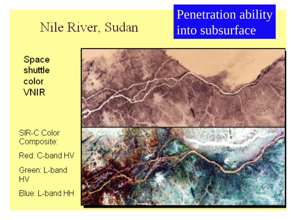
Penetration abilityinto subsurface
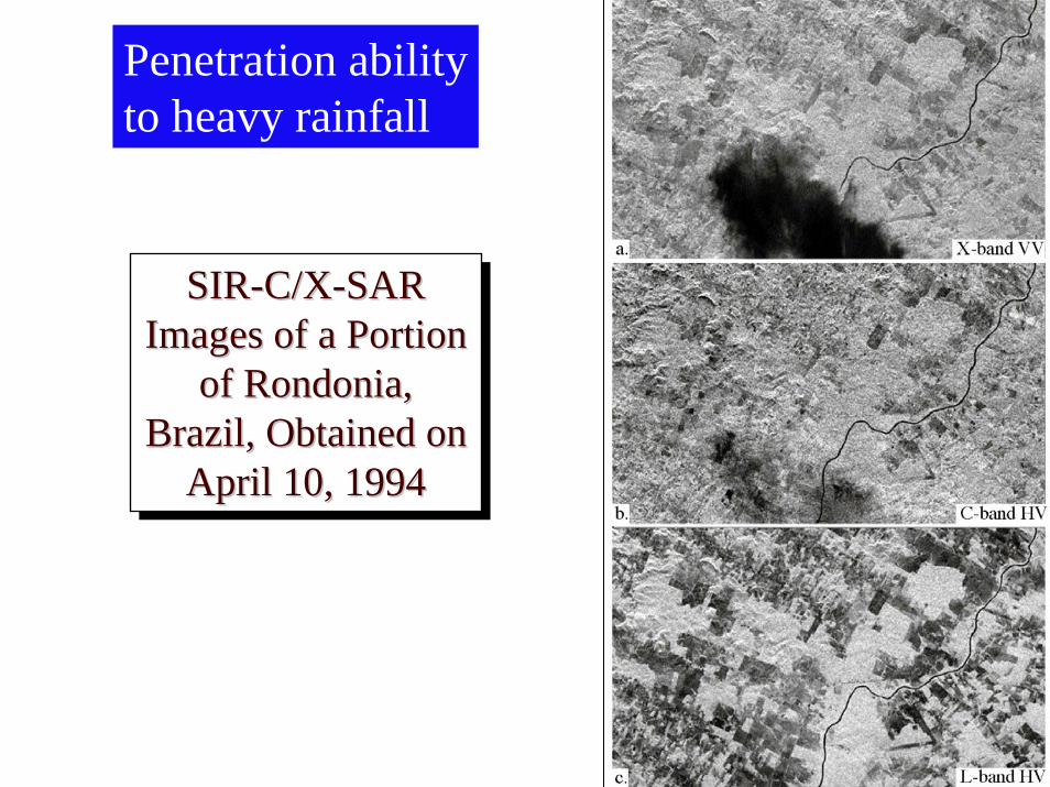
Penetration abilityto heavy rainfall
SIR-C/X-SAR Images of a Portion
of Rondonia, Brazil, Obtained on
April 10, 1994
SIRSIR--C/XC/X--SAR SAR Images of a Portion Images of a Portion
of of RondoniaRondonia, , Brazil, Obtained on Brazil, Obtained on
April 10, 1994April 10, 1994
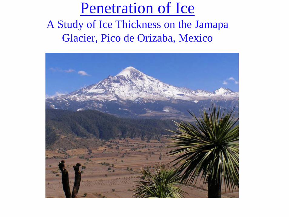
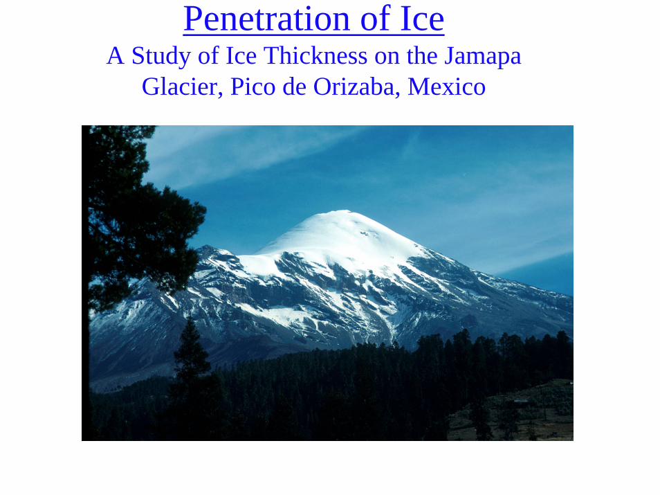
Penetration of IceA Study of Ice Thickness on the Jamapa
Glacier, Pico de Orizaba, Mexico
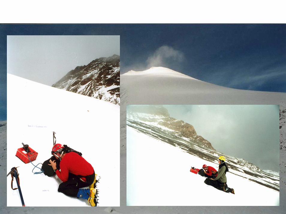
A ground-based radar system (GPR) typically used in shallow ground surveysCan penetrate ice an order of magnitude greater due to dielectric properties400 mHz antenna – approx. 75 cm wavelength100 mHz systems are flown over Antarctica to penetrate 100’s of meters
Penetration of IceA Study of Ice Thickness on the Jamapa
Glacier, Pico de Orizaba, Mexico
Penetration of IceA Study of Ice Thickness on the Jamapa
Glacier, Pico de Orizaba, Mexico
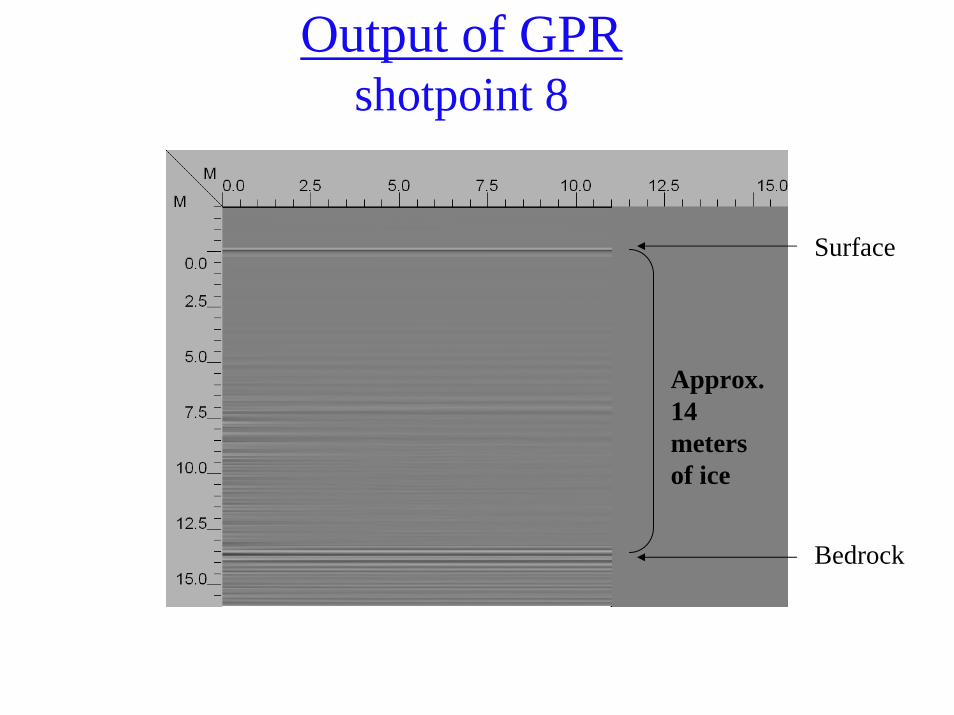
Output of GPRshotpoint 8
Approx. 14 meters of ice
Surface
Bedrock
Radar Shadow
Shadows in radar images can enhance the geomorphology and texture of the terrain. Shadows can also obscure the most important features in a radar image, such as the information behind tall buildings or land use in deep valleys. If certain conditions are met, any feature protruding above the local datum can cause the incident pulse of microwave energy to reflect all of its energy on the foreslope of the object and produce a black shadow for the backslope
Unlike airphotos, where light may be scattered into the shadow area and then recorded on film, there is no information within the radar shadow area. It is black.
Two terrain features (e.g., mountains) with identical heights and fore- and backslopesmay be recorded with entirely different shadows, depending upon where they are in the across-track. A feature that casts an extensive shadow in the far-range might have its backslope completely illuminated in the near-range.
Radar shadows occur only in the cross-track dimension. Therefore, the orientation of shadows in a radar image provides information about the look direction and the location of the near- and far-range
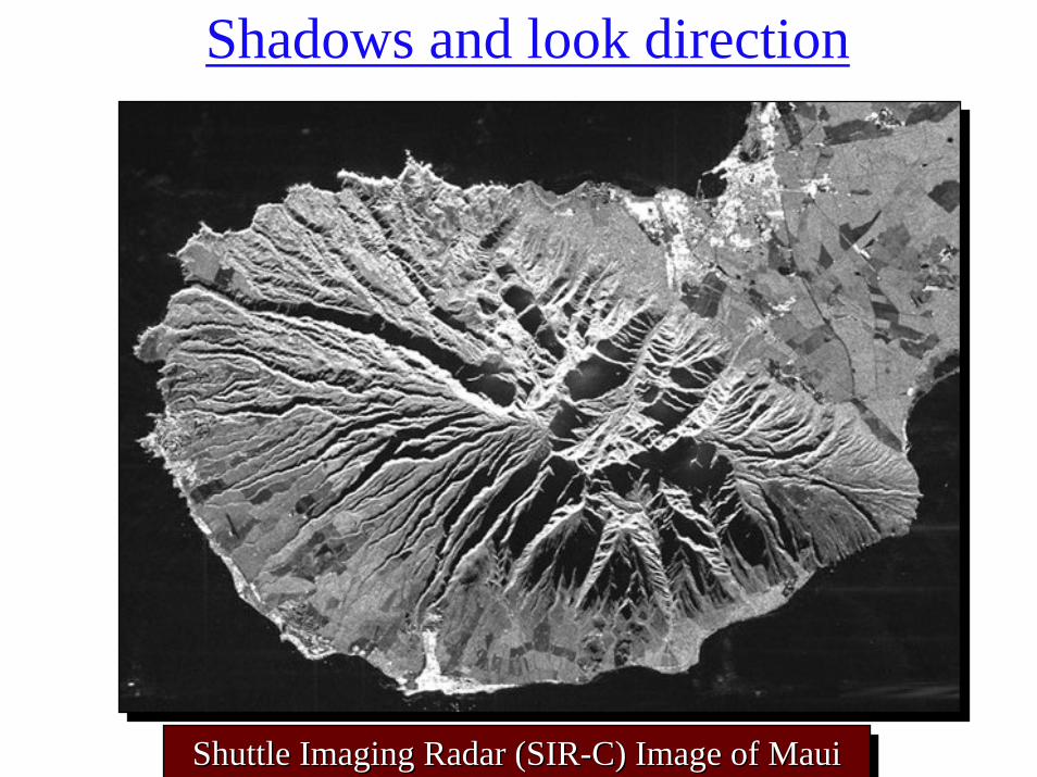
Shadows and look direction
Shuttle Imaging Radar (SIR-C) Image of MauiShuttle Imaging Radar (SIRShuttle Imaging Radar (SIR--C) Image of MauiC) Image of Maui
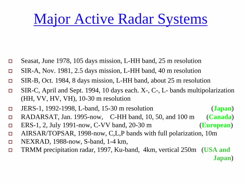
Major Active Radar Systems
Seasat, June 1978, 105 days mission, L-HH band, 25 m resolutionSIR-A, Nov. 1981, 2.5 days mission, L-HH band, 40 m resolutionSIR-B, Oct. 1984, 8 days mission, L-HH band, about 25 m resolutionSIR-C, April and Sept. 1994, 10 days each. X-, C-, L- bands multipolarization(HH, VV, HV, VH), 10-30 m resolutionJERS-1, 1992-1998, L-band, 15-30 m resolution (Japan)RADARSAT, Jan. 1995-now, C-HH band, 10, 50, and 100 m (Canada)ERS-1, 2, July 1991-now, C-VV band, 20-30 m (European)AIRSAR/TOPSAR, 1998-now, C,L,P bands with full polarization, 10m NEXRAD, 1988-now, S-band, 1-4 km, TRMM precipitation radar, 1997, Ku-band, 4km, vertical 250m (USA and
Japan)


![Randolph Glacier Inventory: A Dataset of Global Glacier ... · Zheltyhina. 2012, Randolph Glacier Inventory [v2.0]: A Dataset of Global Glacier Outlines. Global Land Ice Measurements](https://img.dokumen.tips/doc/110x75/5f1037d37e708231d448062a/randolph-glacier-inventory-a-dataset-of-global-glacier-zheltyhina-2012-randolph.jpg)