Embed Size (px)
Citation preview

Metallurgical and Mining Industry6 No.7 — 2017
Engineering science
Engineering science
UDC 531.374; 539.213
Accuracy control for products manufactured by deforming broaching
Ya. Nemyrovskyi
PhD in Technical SciencesCentral Ukrainian National Technical University,
Kropyvnyts’kyy, Ukraine
AbstractThis article presents the research results on the development of scientifically based technological methods for controlling the accuracy parameters of parts processed by deforming broaching. In the course of the research, we felt the necessary to systematize the main types of errors which occur during deforming broaching, and we have also developed the mathematical model of the deformation zone, determining the kinematic, geometric and energy parameters of the process. The model makes it possible to determine the patterns of plastic deformation in the areas of the deformation zone and to reveal that geometric errors appear intensively in non-contact zones of the treated hole. The change in the dimensions of the machined parts has been studied and it has defined the possible variants of axial deformations. In connection with it, the possible variations of the axial deformations within product areas have been determined along with the variations of the axial deformations which could occur with differently thickened cross sections of the products during their deformation. This, in its turn, enables the development of an analytical and experimental model with respect to the axis bending of the workpiece with different thickness under processing.The errors within the external surface of the treated parts are considered with the objective to reveal the technological factors influencing them.Based of the studies, specific technical solutions and scientifically grounded recommendations for parameters accuracy control have been developed. This permits us to obtain the necessary geometric accuracy of the products processed by deforming broaching.Key words: DEFORMING BROACHING, ACCURACY, DEFORMATION ZONE, CONTACT AREA, NON-CONTACT ZONES, DEFORMATION, DIFFERENT THICKNESS, GEOMETRIC ERROR
The problem singled out. One of the priorities in the contemporary machine-building is the development and introduction of resource-saving technologies along with improvements on product quality. Deforming broaching in this respect is applied both as a roughing operation and as a finishing one, it embraces forming and mechanical hardening.
By now, some quality aspects of the metallurgical products obtained by deforming broaching have been studied profoundly and in details. They are roughness, the deepness and degree of hammering harden, utilized plasticity margin [1, 2, 3]. However, the least of the scientific attention has been paid to the parameter of accuracy.
7Metallurgical and Mining IndustryNo.7 — 2017
Engineering scienceIn most of the papers devoted to the accuracy issue,
the authors only process statistical recordings of the experimental data, touch some management issues related to the accuracy parameters in the very narrow aspect and use them for the specific case studies.
The historic review of deforming broaching development is the evidence of the fact that the problem of accuracy assurance was initially not a prime concern for this process. The thing is that the deforming broaching was performed with the deforming elements made from hardened tool steels. In this context, the presence of some insignificant plastic deformation defects on the hole allowed the producers to decrease the surface roughness and to enhance hardness. On the other hand, the service life of such elements was insignificant (several tens of running meters of pipes). As consequence of their low wear resistance and possible traction with the surfaces of the processed holes, their dimensions had notable deviations. That is why the study on their accuracy was limited only with statistical recordings for processed holes dimensions with the dedicated definition of allowable deviations. Moreover, the feasibility of deforming broaching was not also notable. This process was used for working by small plastic deformations with details of small importance, for instance, the bushes of the agricultural machines [4].
However, when diamond tools were introduced to participate in a wide manufacturing application, it became feasible to manufacture and to use deforming tools of carbide hard-alloy metal. With the improvements both on the designs and on the production technologies, the sphere of deforming broaching has been broadening. It became possible to carry out large open-ended plastic deformations, which change the workpiece dimensions, and to deform thick-walled details made from different materials at heavy force loads. High wear resistance and high strength of carbide deforming elements allowed now processing ten of running kilometers of pipes without noticeable wear [5, 6, 7]. This greatly improved the accuracy of the processed holes.
However, when deformation broaching started enlarging its spheres of application, the problems to provide the required geometric accuracy of processing occurred much more frequently. The feasibility to carrying out open-ended deformation during processing workpieces of different thickness always brings into existence such kind of geometric error as the finished workpiece axial bending. Efficient methods of fighting this error are absent. The authors [5] offer to apply additional operation of dressing for thereof, but they note that dressing gives a birth to the new error type of “cutting”.
Furthermore, the deformation of pipes with different thickness is accompanied by a reduction in values of ultimate strains, calculated by the models stated in paper [2], however, it does not take into account the important boundary values of GOST maximum permissible deviations of wall thickness. When processing such a pipe, firstly thin-walled segment is deformed while thick-walled one may remain rigid, not touched. This diminishes the margin of plasticity value and may cause localized destruction of a workpiece, or loss of deformation stability, that is, necking formation.
Additionally, along with a broader application sphere for the deforming broaching, there arises the problem to assure the geometric accuracy of the products, which have the specific demands for hole processing: the hole accuracy should be not higher than the 7th quality class, but the axis straightness tolerance should not exceed 1 mm per one meter of a pipe length. Such products may be shortlisted as follows: hydraulic cylinders of actuators and pneumatic cylinders actuators, cylinders of crude-oil pumps, pit props, drive shafts, ducts, purpose-made chambers, etc.
Eventually, it is now becoming apparent that for the efficient implementation and use of high productive process of deforming broaching in the industry it is necessary to examine the issue of the process accuracy and the ways to ensure it in detail.
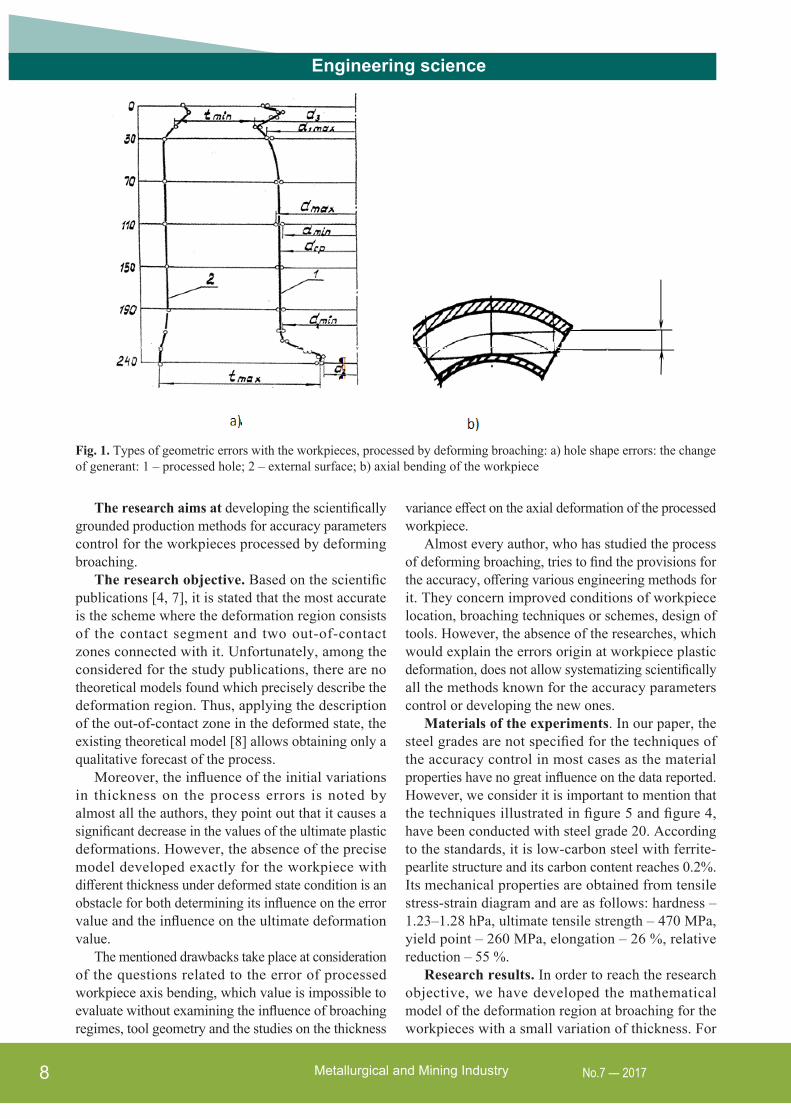
Research background. As a matter of priority, let us consider what types of geometrical errors are typical for workpieces processed by deforming broaching. Following the analysis of the earlier publications, which address the shapes of the workpieces, measurement data [8] and recommendations [9, 10], we have summarized all the types of geometric errors to occur with the holes processed by deforming broaching technique. They are illustrated in Figure 1a as follows:
• ovalty of the hole, (yov=dmax-dmin );• deviation from cylindricity: taper, (yкон=
=d1max-d1min ), barreling (yd=daverage-d2 ), lobing (ylob= =d3x-daverage );
• maximum error of the processed hole along its length (Δd1=d3-d2 ).
Moreover, besides the above mentioned types of errors there also occurs axial bending (Figure 1b) if the differently thickened workpiece undergoes open-ended deformations of a quite large degree.
Beyond argument is the fact that all the types of errors are the results of plastic deformation over the workpiece. Therefore, it is impossible to determine the rooting reasons of the geometric errors occurrence and to find the ways to assure their elimination without detailed study of their production deformation mechanics.
Metallurgical and Mining Industry8 No.7 — 2017
Engineering science
The research aims at developing the scientifically grounded production methods for accuracy parameters control for the workpieces processed by deforming broaching.
The research objective. Based on the scientific publications [4, 7], it is stated that the most accurate is the scheme where the deformation region consists of the contact segment and two out-of-contact zones connected with it. Unfortunately, among the considered for the study publications, there are no theoretical models found which precisely describe the deformation region. Thus, applying the description of the out-of-contact zone in the deformed state, the existing theoretical model [8] allows obtaining only a qualitative forecast of the process.
Moreover, the influence of the initial variations in thickness on the process errors is noted by almost all the authors, they point out that it causes a significant decrease in the values of the ultimate plastic deformations. However, the absence of the precise model developed exactly for the workpiece with different thickness under deformed state condition is an obstacle for both determining its influence on the error value and the influence on the ultimate deformation value.
The mentioned drawbacks take place at consideration of the questions related to the error of processed workpiece axis bending, which value is impossible to evaluate without examining the influence of broaching regimes, tool geometry and the studies on the thickness
variance effect on the axial deformation of the processed workpiece.
Almost every author, who has studied the process of deforming broaching, tries to find the provisions for the accuracy, offering various engineering methods for it. They concern improved conditions of workpiece location, broaching techniques or schemes, design of tools. However, the absence of the researches, which would explain the errors origin at workpiece plastic deformation, does not allow systematizing scientifically all the methods known for the accuracy parameters control or developing the new ones.
Materials of the experiments. In our paper, the steel grades are not specified for the techniques of the accuracy control in most cases as the material properties have no great influence on the data reported. However, we consider it is important to mention that the techniques illustrated in figure 5 and figure 4, have been conducted with steel grade 20. According to the standards, it is low-carbon steel with ferrite-pearlite structure and its carbon content reaches 0.2%. Its mechanical properties are obtained from tensile stress-strain diagram and are as follows: hardness – 1.23–1.28 hPa, ultimate tensile strength – 470 MPa, yield point – 260 MPa, elongation – 26 %, relative reduction – 55 %.
Research results. In order to reach the research objective, we have developed the mathematical model of the deformation region at broaching for the workpieces with a small variation of thickness. For
Fig. 1. Types of geometric errors with the workpieces, processed by deforming broaching: a) hole shape errors: the change of generant: 1 – processed hole; 2 – external surface; b) axial bending of the workpiece

9Metallurgical and Mining IndustryNo.7 — 2017
Engineering scienceits construction, there was used strain-energy method, which incorporates the variations in functional of all the external and internal forces acting in deformation, and there were also applied the parameters of kinematically admissible fields of deformation velocities. The scheme of the deformation region and its principle geometric and kinematic parameters are shown in Figure 2.
The full functional of internal W and external QV3 forces in accordance with the dedicated variation concepts can be expressed as follows:
3 min− =W QV (1)
where Q – force of broaching, V3 – velocity of material flow at the edge of deformation region.
The full functional of the deformation region location is equal to the sum of the functionals of its three zones.
The kinematically admissible field of the velocities for the given scheme of the deformation region has been developed. According to this, the velocity of the circumferencial strain is as follows:
ϕ′
ξ = zrVr
(2)
where Vz – the projection of the velocity of the processed material flow on the middle layer of the workpiece directed along the axis; ′r - the change of the radius of the middle layer along the axis.
Let us consider the relation between the velocity of axial deformation and the velocity of circumferential strain for the middle layer, then as written:
0
0ϕ
ξ=ξ
zK (3)
where К - the coefficient of axial deformation, which is within the limits of each zone and has the constant value as K1, K2, K3.
Fig. 2. Scheme of plastic deformation region
If we recall expression (3), then the velocity of axial deformation for the first zone and the third one is as written:
1,3 1 1′ ′′′ξ = − +
z
rV K r tr
(4)
where 1t - the distance from the middle layer of wall thickness material in the first zone or/and the third zone.
For the second zone, it can be described as given:
2 2′
ξ = −z zrV Kr .
The geometry of the middle layer r= f (z) of the contact segment can be described by the straight line equation, whereas that of the out-of-contact zones - by polynomials of fourth power. In this context we take into account the boundary conditions of each zone, and also the conditions of the kinematic connection on the boundaries of the zones.
The capacity of plastic deformations of the contact zone is written as:
22
2 1
22
2 2 2 2
2
4 1
+
−
′ ′= πτ − +∫ ∫t
l
s zt l
W dt V r K K dz (5)
while the capacities of the out-of-contact zones (1 and 3) are as follows:
1,31
1,3
2 2 2
1,3 1,3 1,3 1,3 1,3 1,30
2
4
+
−
′ ′ ′ ′ ′ ′′′ ′ ′′′ ′= πτ − + + + ∫ ∫
tl
s zt
r r r rW dt V r K r t K r t dzr r r r
(6)
where Vz, t, r/, r///, l, K have their constant values within each zone.
The changes in the velocity of the axial flow and the wall thickness in each zone of the deformation region are determined under conditions of non-compressing and continuity of deformation.
The five independent parameters 1K , 2K , 3K , 1l , and 3l are the varying parameters, which should provide the
minimum for functional (1). The ground expressions of r= f (z), Vz, t
for each zone of the deformation region
are provided by publication [11].In accordance with the developed model, the
calculations are carried out with the algorithm, based on the method of successive approximation [11]. In view of the results of the latter iteration, we have determined geometric, kinematic and energy
Metallurgical and Mining Industry10 No.7 — 2017
Engineering scienceparameters of the deformation region: 1l , 3l , 1K , 2K ,
3K , 2l and lc , 1W , 2W , 3W ,Wfr ,W , where lc is the contact area length, Wfr - power of friction force...
Eventually, the examination of the obtained results is carried out by comparing the calculated data with the experimental ones. Their concurrency evidences validity of the model and determines conditions of its use [11].
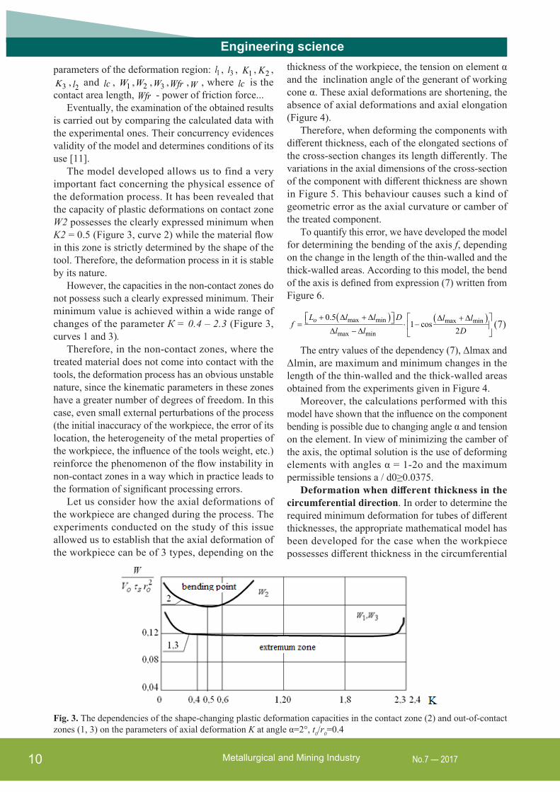
The model developed allows us to find a very important fact concerning the physical essence of the deformation process. It has been revealed that the capacity of plastic deformations on contact zone W2 possesses the clearly expressed minimum when K2 = 0.5 (Figure 3, curve 2) while the material flow in this zone is strictly determined by the shape of the tool. Therefore, the deformation process in it is stable by its nature.
However, the capacities in the non-contact zones do not possess such a clearly expressed minimum. Their minimum value is achieved within a wide range of changes of the parameter К = 0.4 – 2.3 (Figure 3, curves 1 and 3).
Therefore, in the non-contact zones, where the treated material does not come into contact with the tools, the deformation process has an obvious unstable nature, since the kinematic parameters in these zones have a greater number of degrees of freedom. In this case, even small external perturbations of the process (the initial inaccuracy of the workpiece, the error of its location, the heterogeneity of the metal properties of the workpiece, the influence of the tools weight, etc.) reinforce the phenomenon of the flow instability in non-contact zones in a way which in practice leads to the formation of significant processing errors.
Let us consider how the axial deformations of the workpiece are changed during the process. The experiments conducted on the study of this issue allowed us to establish that the axial deformation of the workpiece can be of 3 types, depending on the
thickness of the workpiece, the tension on element α and the inclination angle of the generant of working cone α. These axial deformations are shortening, the absence of axial deformations and axial elongation (Figure 4).
Therefore, when deforming the components with different thickness, each of the elongated sections of the cross-section changes its length differently. The variations in the axial dimensions of the cross-section of the component with different thickness are shown in Figure 5. This behaviour causes such a kind of geometric error as the axial curvature or camber of the treated component.
To quantify this error, we have developed the model for determining the bending of the axis f, depending on the change in the length of the thin-walled and the thick-walled areas. According to this model, the bend of the axis is defined from expression (7) written from Figure 6.
( ) ( )max min max min
max min
0.51 cos
2 + ∆ + ∆ ∆ + ∆ = ⋅ − ∆ − ∆
oL l l D l lf
l l D(7)
The entry values of the dependency (7), Δlmax and Δlmin, are maximum and minimum changes in the length of the thin-walled and the thick-walled areas obtained from the experiments given in Figure 4.
Moreover, the calculations performed with this model have shown that the influence on the component bending is possible due to changing angle α and tension on the element. In view of minimizing the camber of the axis, the optimal solution is the use of deforming elements with angles α = 1-2о and the maximum permissible tensions a / d0≥0.0375.
Deformation when different thickness in the circumferential direction. In order to determine the required minimum deformation for tubes of different thicknesses, the appropriate mathematical model has been developed for the case when the workpiece possesses different thickness in the circumferential
Fig. 3. The dependencies of the shape-changing plastic deformation capacities in the contact zone (2) and out-of-contact zones (1, 3) on the parameters of axial deformation K at angle α=2°, t0/r0=0.4

11Metallurgical and Mining IndustryNo.7 — 2017
Engineering science
Fig. 4. The dependence between the total change in the component length and the relative thickness of the wall (d0=40 mm, a/d0=0.125, Σa/d0=0.075, angle α: 12°(1), 8°(2), 4°(3), 2°(4); material is steel 20)
Fig. 5. Variations in axial deformation values in the cross section of the processed workpiece (a/d0=0.025 at angle α: tmin=0.1, φ=0; tmax=0.15, φ=180. α: 1 – 12°, 2 – 8°, 3 – 4°, 4 – 2°; material is steel 20)
Fig. 6. Axial camber of the component with different thickness
direction (Figure 7). From this model we can develop the relation between the degree of deformation ε and the angle of the plastic zone 0ϕ
0
11
0 0
00
( )1 3 12 ( )
ϕ ϕσ ε = − ϕ π ϕ ∫
nnT t
dB t
, (8),
where σt, В, n are the parameters, approximating the curve of the material flow under processing.
Eventually, by the numerous calculations for different materials and thickness, we have obtained the calculated dependencies of ε on φ0. They allow us to develop the algorithm and to use it with the objective to determine the required minimum deformation that provides for the deformation of the entire volume of the workpiece with different thickness.
In processing odd-shaped components, it is necessary to take into account their protrusions and blocks, which give significant variations in the thickness of the wall in the cross-section.
For thereof, we have developed a new solution to have an ensured localization of plastic deformation by means of forming untouched by deformation rigid areas in workpieces (Figure 8). Theoretical model for
Fig. 7. Deformation diagram for the tube with different thickness
Fig. 8. Workpiece with rigid and plastic zones

Metallurgical and Mining Industry12 No.7 — 2017
Engineering sciencedeforming a tube with rigid and plastic sections has also been developed.
Based on the model, the allowed relation between the thicknesses of the walls and the plastic (tp) and the rigid (tr) zones has been determined, which ensures the localization of the deformations on the plastic zones:
1
213
ε−β σ
= ε σ + −β
p Tnnr
пл T
t et
K A (9)
where: Kp>1; 0
4∆β =
πd
We also studied the influence of the initial inaccuracies of the hole on the geometric errors at processing. It has been established that the original inaccuracy hardly influences the inaccuracy in the processed hole in open-ended plastic deformation. However, the influence of the former is observed when workpieces with small tensions and minor total deformations of the hole (workpieces with a wall thickness close to the infinite or those made of low-plastic materials) are processed by thereof. Moreover, the effective use of the deforming broaching in this case is possible only if high accuracy of the hole is achieved by previous operations. Pursuing the objective of inaccuracy minimizing, it is important to pay attention to the value of the total plastic deformation of the hole as the operating condition is limited by as follows:
• the required precision of the hole geometry (for plastic materials);
• the required accuracy of the hole geometry and the plasticity margin of the material under processing (for semicircular materials).
Herewith, it is necessary to take into account the production requirements for the suitable roughness and the surface strength.
Separately, we would like to focus on the errors on the external surface of the workpiece. In most cases, they determine the tolerance for subsequent processing. Such errors are formed on the areas adjacent to the ends of the workpiece due to the absence of stationariness in deformation at the entrance and the exit of the deforming element. The experiments conducted showed that the most significant influence on the growth of this error is made by angle α and the tension on the element, as well as by the design features of the workpiece and the conditions of its location.
The analysis of the above-mentioned material suggests that the errors of the components treated with deforming broaching are formed within both the contact and the non-contact areas of the deformation
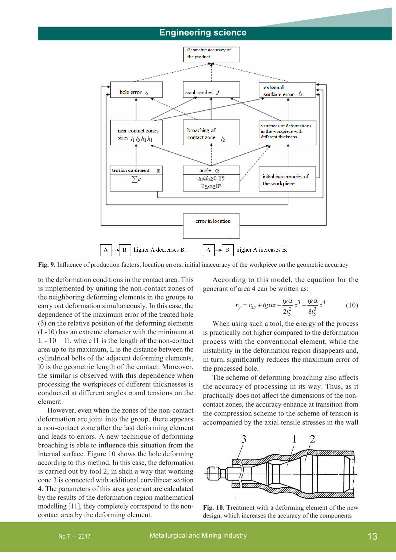
region. Their occurrence is explained by the instability of the material flow in this deformation region as well as the effect of the initial inaccuracy of the workpiece and the error of its location. Let us consider the effect of these factors on geometric accuracy in the form of the scheme (Figure 9).
The following makes it possible to determine the main ways of reducing geometric errors during deformation.
• influence on deformation in the non-contact zones;• influence on deformation in the contact area;• elimination of the external influence that distorts
the axial direction of deformation, that is, the initial inaccuracy of the workpiece and the errors of its location;
• elimination of the external surface errors.As we noted earlier, the deformation in different
zones belonging to the deformation region is the comprehensive process of workpiece plastic forming. Therefore, its disturbance in the form of deformation instability in each of the zones within the deformation region inevitably affects the appearance of the geometric errors in the entire detail. Thus, the prevention of instability of the material flow is to be carried out in all the zones of the deformation region and, first of all, in the non-contact ones, where, as shown in Figure 3, instability of the flow occurs even when the absence of the external deforming factors.
As follows from the universal laws of mechanics and stability theory, the very beginning of the motion instability or, on the contrary, instability vanishing in mechanical systems are very much dependent on the smallest manifestations of disturbing or stabilizing factors. As for our process, it follows that even the smallest in value but active technological influence on the zone of the deformation region, especially on the non-contact ones, can significantly affect the stability of the entire deformation process and naturally reduce the processing errors.
Let us consider in more detail the implementation of the solutions intended to reduce the geometric errors.
Influence on deformation in the non-contact zones. The methods to influence the deformation process in the non-contact zones can vary in the design and technological techniques, based on the results of the above-mentioned studies. For example, the influential factor could be the choice of rational deformation conditions or regimes and geometry of the tool, it allows you to reduce the size of the non-contact areas.
One can influence the material flow in these zones with imposing additional stabilizing bonds, with which the deformation in the non-contact zones approaches
13Metallurgical and Mining IndustryNo.7 — 2017
Engineering science
Fig. 9. Influence of production factors, location errors, initial inaccuracy of the workpiece on the geometric accuracy
to the deformation conditions in the contact area. This is implemented by uniting the non-contact zones of the neighboring deforming elements in the groups to carry out deformation simultaneously. In this case, the dependence of the maximum error of the treated hole (δ) on the relative position of the deforming elements (L-10) has an extreme character with the minimum at L - 10 = l1, where l1 is the length of the non-contact area up to its maximum, L is the distance between the cylindrical belts of the adjacent deforming elements, l0 is the geometric length of the contact. Moreover, the similar is observed with this dependence when processing the workpieces of different thicknesses is conducted at different angles α and tensions on the element.
However, even when the zones of the non-contact deformation are joint into the group, there appears a non-contact zone after the last deforming element and leads to errors. A new technique of deforming broaching is able to influence this situation from the internal surface. Figure 10 shows the hole deforming according to this method. In this case, the deformation is carried out by tool 2, in shch a way that working cone 3 is connected with additional curvilinear section 4. The parameters of this area generant are calculated by the results of the deformation region mathematical modelling [11], they completely correspond to the non-contact area by the deforming element.
Fig. 10. Treatment with a deforming element of the new design, which increases the accuracy of the components
According to this model, the equation for the generant of area 4 can be written as:
3 42 33 32 8α α
= + α − +y элtg tgr r tg z z zl l
(10)
When using such a tool, the energy of the process is practically not higher compared to the deformation process with the conventional element, while the instability in the deformation region disappears and, in turn, significantly reduces the maximum error of the processed hole.
The scheme of deforming broaching also affects the accuracy of processing in its way. Thus, as it practically does not affect the dimensions of the non-contact zones, the accuracy enhance at transition from the compression scheme to the scheme of tension is accompanied by the axial tensile stresses in the wall

Metallurgical and Mining Industry14 No.7 — 2017
Engineering scienceof the component. Their presence stabilizes the flow of the material in the deformation region, reduces perturbation of the circumferential deformation and thus decrease the geometric errors of the processed hole.
The scheme with axial deformation limits [6] is an improved deforming broaching scheme and, as experiments have shown, it allows us to control the level of axial stresses at processing. It should be noted here that commonly the change in the value of axial stresses formed along the length of the workpiece is a disturbing factor that negatively affects the flow of the material in the deformation region and causes the significant errors in the machined components. The proposed scheme [6] allows the control over the values of the indicated axial stresses and stabilizes the process of the workpiece deformation, which, in turn, prevents the appearance of the relevant errors.
Influence on deformation in the contact area. Another important technique to improve the accuracy of processed components is to influence the deformation in the contact area. Similarly to the work with the non-contact zones, this can be also done by choosing rational broaching regimes or conditions and geometry of the tool, which allows reducing the variation in the changes within the axial parameters of the workpiece. Particularly, such kind of influence is essentially efficient against the error of the axial bending, the latter is peculiar to differently thickened component treatment. Thus, the calculations with expression (7) clearly define the optimal values of angle α and tensions, which are able to reduce the axial camber of the finished workpieces.
Furthermore, the experiment on the processed workpiece in the deformed state has proved that the broaching scheme really affects the axial deformation. This brings the idea that the choice of the suitable broaching scheme is one of the solutions that can affect the material flow in the contact area. We have found that when applying the scheme with limited axial deformation, those errors which are caused by the presence of the local change in the thickness of the wall (by collars, lances, grooves) can be eliminated. However, this scheme has a specific area of its use - broaching of thin-walled workpieces of a considerable length. It should also be noted that the tensile scheme that is commonly used in the deforming process requires workpiece location to be carried out by employing collars or grooves on the external surface adjacent to the end. This bears the changes in the thickness of the wall within the area of its location, which, in turn, affects the radial and the axial deformations and results in non-negligible
errors are detected. In order to eliminate this, we have developed another new deforming method (Figure 11): workpiece area 1 used for the location should be previously deformed by deforming element 2 to the specific value of as written:
e1=(0.85÷0.9)×e2 ,
where e2 is the required deformation of the hole.Thereafter, base 3 is prepared for fixing the
workpiece (e.g., cut-out half-circles 4 and 5) in support 6 for the final treatment. In the process of deforming by the appropriate elements (7, 8, 9), the area with differences in the wall thickness is almost untouched by deforming. However, that slight deformation (e2- e1), which ever occurs, serves only for plastic deformation of the surface layer finishing. Thus, one can decrease the maximum error of the hole almost twice (from 0.73 to 0.36 mm) by using this method as workpieces tension pattern with the parameters as follows: workpiece sizes of t0/d0 = 0.25 L = = 250 mm; collar of t0/d0 = 0.35 and 15 mm in length; the deforming element at angle α = 12 and tension a/d0 = 0.375.
Additionally, the above-described method of deforming the components with different thickness can be distinguished as a separate technique for improving the accuracy at the treatment of the components with nonuniform rigidity, namely, those ones which show
Fig. 11. Preliminary preparation of the workpiece base for broaching by the tensile pattern
15Metallurgical and Mining IndustryNo.7 — 2017
Engineering sciencethe greater difference in rigidity within the cross-section (Figure 8), as the plastic deformation is localized on plastic segments of the cross-section while the areas with larger thickness remain rigid without deformation.
In the case of processing cast iron holes, which is carried out with small tensions and minor total deformations, there is a stable shrinkage of the hole, which may exceed the nominal tension [12]. This means that the conditions are created for additional plastic deformation on the surface of the hole without deforming the area near the external surface.
Such an additional plastic deformation can be performed by using the tool backing through the as-processed hole. At that, the inclination angle of the generant of back taper belonging to deforming element α1 should be greater than angle α. This inclination angle can be determined in accordance with the dependence (11) obtained in the current research [12]:
α1 = (3.24 – 3.96)α0.96 (11)
In this case, the plastic deformation takes place only within the surface layer, while the external surface is deformed elastically, its destruction is excluded in such a way. This work does not distort the shape of the hole, however, rather improves its accuracy by reducing and leveling high parameter of rigidity Rz.
Elimination of the external influence. The third technique of accuracy control at deforming broaching is the elimination of the external factors that distort the axial symmetry of the workpiece deformation. To such external disturbing factors, it is necessary to add the errors of the tool location and the workpiece location, that is, their out-of-alignment behavior. Obviously, by eliminating this problem one can significantly enhance the accuracy of processing. This is achieved by the design and production methods described more in details below and generalized as the choice of the optimal broaching scheme and its further improvement, which is able to permit not only the material flow stabilizing in the deformation region, but also to create the necessary conditions for avoiding the tool misalignment with respect to the workpiece.
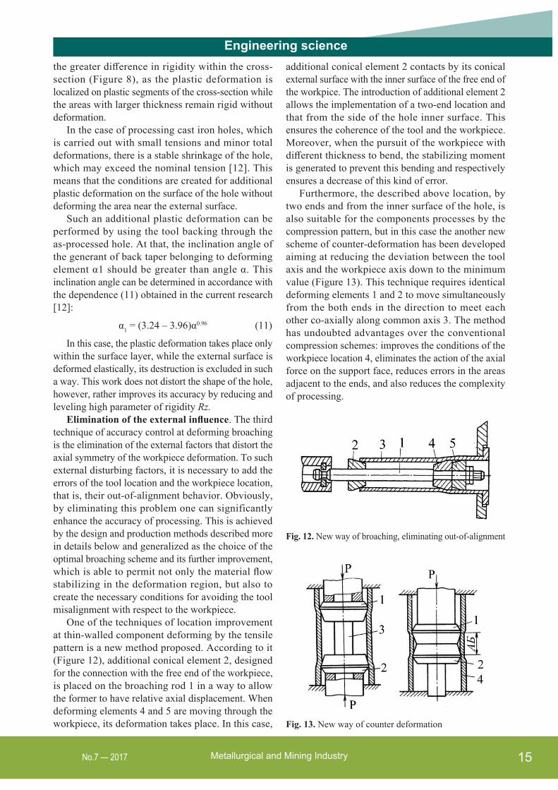
One of the techniques of location improvement at thin-walled component deforming by the tensile pattern is a new method proposed. According to it (Figure 12), additional conical element 2, designed for the connection with the free end of the workpiece, is placed on the broaching rod 1 in a way to allow the former to have relative axial displacement. When deforming elements 4 and 5 are moving through the workpiece, its deformation takes place. In this case,
additional conical element 2 contacts by its conical external surface with the inner surface of the free end of the workpice. The introduction of additional element 2 allows the implementation of a two-end location and that from the side of the hole inner surface. This ensures the coherence of the tool and the workpiece. Moreover, when the pursuit of the workpiece with different thickness to bend, the stabilizing moment is generated to prevent this bending and respectively ensures a decrease of this kind of error.
Furthermore, the described above location, by two ends and from the inner surface of the hole, is also suitable for the components processes by the compression pattern, but in this case the another new scheme of counter-deformation has been developed aiming at reducing the deviation between the tool axis and the workpiece axis down to the minimum value (Figure 13). This technique requires identical deforming elements 1 and 2 to move simultaneously from the both ends in the direction to meet each other co-axially along common axis 3. The method has undoubted advantages over the conventional compression schemes: improves the conditions of the workpiece location 4, eliminates the action of the axial force on the support face, reduces errors in the areas adjacent to the ends, and also reduces the complexity of processing.
Fig. 12. New way of broaching, eliminating out-of-alignment
Fig. 13. New way of counter deformation
Metallurgical and Mining Industry16 No.7 — 2017
Engineering scienceThe technique also improves the location on
one of the ends and on the inside surface when in deforming broaching the additional structural elements are involved, namely: front and rear guides. Their application is particularly effective in cases where the front guide contacts the untreated surface due to the elasticity in the radial direction, and the rear with the as-treated one.
Additionally, in some cases, the axial misalignment of a tool with respect to the workpiece can be improved by influencing from the external surface of the workpiece. In this situation, a number of common structures of supports 13 with radially extending support elements can be used to provide rigidity decrease in this direction. The workpiece is centered with the surfaces of the supporting elements and is held by the end on the supporting platforms. If we deform thin-walled workpieces, their outer diameters increase and the carrying and supporting elements elastically dissipate, continuing to locate the workpiece by the support end and the external surface. However, such structures of the supports do not provide the conditions of reliable location for the workpieces with different thickness.
Much more effective for this case is support [14], where location is performed by several supporting cams. The locating cam is a two-shoulder lever, the bearing end of which interacts with the external surface of the workpiece and the other end is connected by a rigid axisymmetric ring that has the feasibility to move in the circumferential direction. At the workpiece deformation, the bearing surfaces of the cams are always reliable in contact with the external surface of the workpiece in order to provide a co-axial location even in the case of the components with different thickness.
The rigid or not deformed supports 6 allow effective work against the following types of errors: the axial bending of the workpiece, the difference in its thickness and the maximum error of the hole.
The previously described method of broaching with the preliminary deformation of the ring section and the base preparation on it for the final deformation also improves the conditions for the base.
The heterogeneity of the mechanical characteristics of the component, which also distorts the axial direction of the deformation, is eliminated by additional stabilizing firing.
Although both the weight of the tool and the weight of the component influence the deformation process, their effect can be eliminated if the deformation is performed on the vertical presses, or if special supports
and devices are applied to accompany and to support the tool during its moving through the workpiece.
Elimination of the external surface errors. The external surface errors are the other notable drawbacks at deformation. They can be obviated by another new deformation scheme developed, according to which the required total deformation is carried out in an even number of passes, with the support face change after the first pass.
The experiments on the implementation of the developed scheme evidence that its use helps to achieve the desired result, that is to provide the geometric accuracy of the external surface after processing.
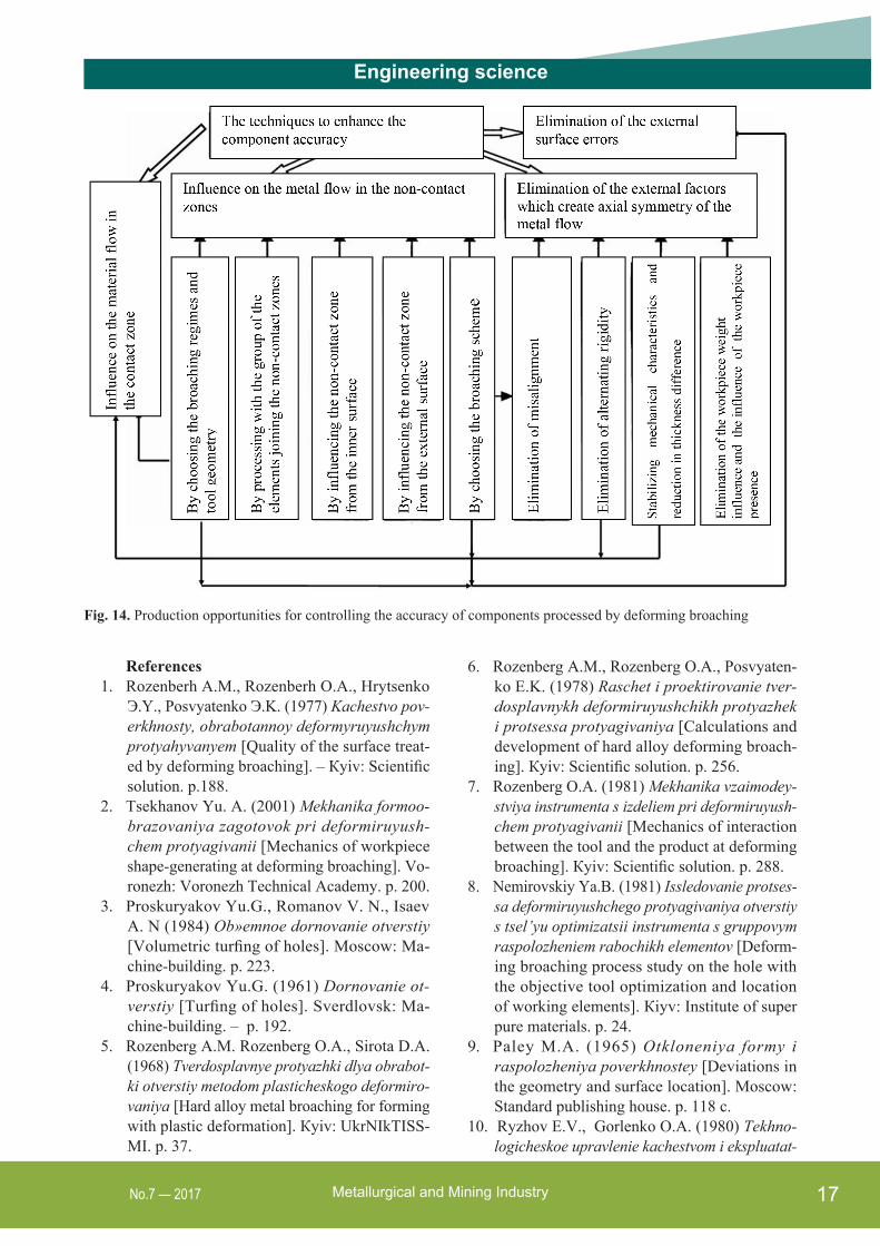
In order to summarize the materials above, we present the accuracy control techniques for the components processed by deforming broaching in the form of the diagram (Figure 14). We consider such diagram allows one to use the obtained results with the objective to select the optimal path for achieving the required accuracy, taking into account available equipment, sizes and technical requirements for the components.
ConclusionsThe analysis conducted in the course of the
reported research allows us to come to the following conclusions.
The geometric errors of the parts processed by deforming broaching are formed in both the contact and the non-contact zones of the deformation region and are caused by: instability of deformation within the deformation region, variation in the circumferential direction when axial deformations of the workpieces with different thickness and by the influence of external perturbing factors (errors of the location, heterogeneity of mechanical properties of the material, initial inaccuracies of the workpiece, etc.). All these distort the axial symmetry of deformation.
The ways to control the accuracy parameters at the deforming broaching have been determined in the current paper, they are directed to fight instability of deformation in the non-contact zones, to reduce circumferential heterogeneity of axial deformation for workpieces with different thickness, to eliminate perturbing factors, which are able to distort the axial direction of deformation, to obviate the errors in the shape of the external surface of the workpiece.
To achieve these targets, the article suggests the developments of the scientifically grounded deformation methods, the new broaching schemes, the tool designs, the rational broaching regimes. All these allow control over the accuracy parameters of the processed products.
17Metallurgical and Mining IndustryNo.7 — 2017
Engineering science
Fig. 14. Production opportunities for controlling the accuracy of components processed by deforming broaching
References1. Rozenberh A.M., Rozenberh O.A., Hrytsenko
Э.Y., Posvyatenko Э.K. (1977) Kachestvo pov-erkhnosty, obrabotannoy deformyruyushchym protyahyvanyem [Quality of the surface treat-ed by deforming broaching]. – Кyiv: Scientific solution. p.188.
2. Tsekhanov Yu. A. (2001) Mekhanika formoo-brazovaniya zagotovok pri deformiruyush-chem protyagivanii [Mechanics of workpiece shape-generating at deforming broaching]. Vo-ronezh: Voronezh Technical Academy. p. 200.
3. Proskuryakov Yu.G., Romanov V. N., Isaev A. N (1984) Ob»emnoe dornovanie otverstiy [Volumetric turfing of holes]. Moscow: Ma-chine-building. p. 223.
4. Proskuryakov Yu.G. (1961) Dornovanie ot-verstiy [Turfing of holes]. Sverdlovsk: Ma-chine-building. – p. 192.
5. Rozenberg A.M. Rozenberg O.A., Sirota D.A. (1968) Tverdosplavnye protyazhki dlya obrabot-ki otverstiy metodom plasticheskogo deformiro-vaniya [Hard alloy metal broaching for forming with plastic deformation]. Кyiv: UkrNIkTISS-MI. p. 37.
6. Rozenberg A.M., Rozenberg O.A., Posvyaten-ko E.K. (1978) Raschet i proektirovanie tver-dosplavnykh deformiruyushchikh protyazhek i protsessa protyagivaniya [Calculations and development of hard alloy deforming broach-ing]. Кyiv: Scientific solution. p. 256.
7. Rozenberg O.A. (1981) Mekhanika vzaimodey-stviya instrumenta s izdeliem pri deformiruyush-chem protyagivanii [Mechanics of interaction between the tool and the product at deforming broaching]. Кyiv: Scientific solution. p. 288.
8. Nemirovskiy Ya.B. (1981) Issledovanie protses-sa deformiruyushchego protyagivaniya otverstiy s tsel’yu optimizatsii instrumenta s gruppovym raspolozheniem rabochikh elementov [Deform-ing broaching process study on the hole with the objective tool optimization and location of working elements]. Кiyv: Institute of super pure materials. p. 24.
9. Paley M.A. (1965) Otkloneniya formy i raspolozheniya poverkhnostey [Deviations in the geometry and surface location]. Мoscow: Standard publishing house. p. 118 с.
10. Ryzhov E.V., Gorlenko O.A. (1980) Tekhno-logicheskoe upravlenie kachestvom i ekspluatat-
Metallurgical and Mining Industry18 No.7 — 2017
Engineering sciencesionnymi svoystvami poverkhnostey [Production control over quality and operational properties of surfaces]. Tula: Tula polytechnic institute. p. 97.
11. Nemirovskiy Ya.B., Tsekhanov Yu.A. (2001) Primenenie variatsionnykh printsipov dlya anal-iza energeticheskikh i kinematicheskikh para-metrov protsessa deformiruyushchego protya-givaniya [Application of variation principles for the analysis of energy and kinematic parameters in the deforming broaching process]. Rezanie i instrument v tekhnologicheskikh sistemakh [Cut-ting operations and tools in production systems]. International conference proceedings of Nation-al technical university. No. 60. pp. 154-159.
12. Yeromin P.M. (2015) Pidvyshchennia efektyv-nosti obrobky otvoriv u detaliakh iz chavuniv kombinovanym protiahuvanniam [Efficiency increase for processing holes of cast iron prod-ucts by broaching]. Thesis in brief booklet for PhD degree. 05.03.01. 20 p.
13. Broaching machine support. 606692 ССAVER-AGE : МКИ В 23 D 41/02 / A.M. Rozenberg, O.A. Rozenberg, E.I. Gritsenko and others. № 2426255/25–08 ; submitted 03.12.76; pub-lished 15.05.78. No 8. 3 p.
14. Support for deforming broaching 761172 ССAVERAGE: В23D41/04/ О.A. Anpilogov, Yu.F. Busel, A.D. Kritskiy and others. No. 1836811/25-27. submitted 16.10.7; pub-lished 07.09.80, No 33. 5p.