Embed Size (px)
Citation preview
EBVAccumulators
OLAER EBV | Low pressure bladder type conform to EC regulations
The Professional Choice

2 OLAER | EBV
www.olaer.com
How to safeguard your installations?The principle of precaution is always essential for everything related to the Oil activity. It is based on anticipating and adopting measures to prevent major risks.
Sudden flow changes in pipes (starting and stopping a pump, opening and closing a valve) cause pressure waves that propagate in pipes and cause leaks at connections, maladjustments of regulation devices, measurement devices, deterioration to the pump and the network. If correctly sized, the new range of EBV accumulators absorbs these oscillations, guaranteeing operation of your installations in complete safety within an acceptable pressure range.With our new EBV range, we offer to measure overpressures on your network and make a commitment to provide the best technical solution adapted to your needs, so that you can benefit from our experience.
OLAER contributes to improving the safety of your system.
An example application
Considering the need to make its network of truck
loading stations conform, an oil depot would like to
optimize operation of his installations by taking all
safety measures necessary in this field.
Comparative survey of pressures in an oil depot
Service pressure (Bar)
With EBV accumulator
Without EBV accumulator
Time (seconds)0
3
6
9
12
Risk area
Safety area
Risk Area
OLAER | EBV 3
The Professional Choice
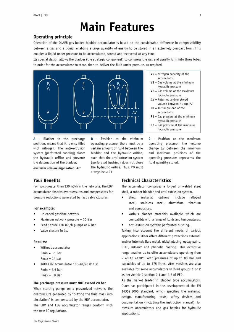
A - Bladder in the precharge position, means that it is only filled with nitrogen. The anti-extrusion system (perforated bushing) closes the hydraulic orifice and prevents the destruction of the bladder.
Maximum pressure differential : 4:1
B - Position at the minimum operating pressure; there must be a certain amount of fluid between thebladder and the hydraulic orifice, such that the anti-extrusion system (perforated bushing) does not close the hydraulic orifice. Thus, P0 must always be < P1.
C - Position at the maximum operating pressure: the volume change V between the minimum and maximum positions of the operating pressures represents the fluid quantity stored.
Your BenefitsFor flows greater than 130 m3/h in the networks, the EBV
accumulator absorbs overpressures and compensates for
pressure reductions generated by fast valve closures.
For example:• Unleaded gasoline network
• Maximum network pressure = 10 Bar
• Feed : three 130 m3/h pumps at 4 Bar
• Valve closure in 3s.
Results:• Without accumulator
Pmin = -1 Bar
Pmax = 14 bar
• With EBV accumulator 100-40/90 01180
Pmin = 2.5 bar
Pmax = 8 Bar
The precharge pressure must NOT exceed 20 bar
When starting pumps on a pressurized network, the
overpressure generated by “putting the fluid mass into
circulation” is compensated by the EBV accumulator.
The EBV and ELG accumulator ranges conform with
the new EC regulations.
Technical CharacteristicsThe accumulator comprises a forged or welded steel
shell, a rubber bladder and anti-extrusion system.
• Shell material options include alloyed
steel, stainless steel, aluminium, titanium
and composites.
• Various bladder materials available which are
compatible with a range of fluids and temperatures.
• Anti-extrusion system; perforated bushing.
Taking into account the different needs of various
applications, Olaer offers different protections external
and/or internal: Bare metal, nickel plating, epoxy paint,
PTFE, Rilsan® and phenolic coating. This extensive
range enables us to offer accumulators operating from
– 40 to +130°C with pressures of up to 80 Bar and
capacities of up to 575 litres. Atex versions are also
available for some accumulators in fluid groups 1 or 2
as per Article 9 section 2.1 and 2.2 of PED.
As the market leader in bladder type accumulators,
Olaer has participated in the development of the EN
14359:2006 standard, which specifies the material,
design, manufacturing, tests, safety devices and
documentation (including the instruction manual), for
pressure accumulators and gas bottles for hydraulic
applications.
Main FeaturesOperating principleOperation of the OLAER gas loaded bladder accumulator is based on the considerable difference in compressibility
between a gas and a liquid, enabling a large quantity of energy to be stored in an extremely compact form. This
enables a liquid under pressure to be accumulated, stored and recovered at any time.
Its special design allows the bladder (the strategic component) to compress the gas and usually form into three lobes
in order for the accumulator to store, then to deliver the fluid under pressure, as required.
V0 = Nitrogen capacity of the accumulatorV1 = Gas volume at the minimum hydraulic pressureV2 = Gas volume at the maximum hydraulic pressureV = Returned and/or stored
volume between P1 and P2P0 = Initial preload of the accumulatorP1 = Gas pressure at the minimum hydraulic pressureP2 = Gas pressure at the maximum hydraulic pressure
P2
2V
C
P1
1V
B
P0
0V
A V

4 OLAER | EBV
www.olaer.com
How to size?OLAER has developed software to design accumulators to absorb the shock. You can use two different procedures to evaluate and to find a shock absorber solution with guaranteed results*. * (complete procedure)
• Pressure readings and validation of assumptions on site• Shock absorber calculation starting from a correctly filled in questionnaire with isometric drawing (supplied by you)• Validation of calculations on site by pressure readings after installation of the selected accumulators
ProcedureComplete Partial
Formular to return
Company : ........................................ Service : ................................. Name : .............................................
Phone : ............................................ E-mail : ................................... Fax : ................................................
I want : (tick the appropriate box) A complete procedure A partial procedure
Your installation
Your installation (tick the appropriate box)
Hmt : Total pressure head - Hg : geometric head - ∆P : Pressure loss - Ø : Pipe diameter - Hd : Intake head - He : Static head
Application type (fill in according to your installation)
Starting and stopping the pump (fig. 1) Pump stop time (secondes) : ..................................Pressurized intake (fig. 2) Pump stop time (secondes) : ...................................Closes valves (fig. 3) Valves closure time (secondes) : ...............................
Fig. 1 Fig. 2 Fig. 3
Fluid : ............................................................
Pipe material : ................................................
Pipe lengh (L) : ............................................. m
Pipe inner diameter (Ø) : ................................ mm
Pipe thickness : ............................................. mm
Max. flow rate of the pump : ........................... L/mn
Max.flow rate at valve closure : ......................... L/mn
Total pressure head (Hmt) : ............................. Mcl
Geometric head (Hg) : .................................... Mcl
Intake head (Hd) : ........................................ Mcl
Static head (He) : .......................................... Mcl
Plumbing sectorTable provided for guidance, valid for a residual fluid pressure of about 3 bar at the end of the column and for a flow speed in the pipe of 2.5 m/s max. Precharge pressure equivalent to the residual pressure at the end of the column. Precharge done by us at the factory outlet.
Pipe Ø Pipe length or height (m)
10-20-30 40-50-60 70-80-908/13 OLG 0.13-50/00 01925 OLG 0.13-50/00 01925 OLG 0.13-50/00 01925
15/21 OLG 0.13-50/00 01925 OLG 1-20/00 03325 OLG 1-20/00 03325
20/27 OLG 0.13-50/00 01925 OLG 1-20/00 03325 OLG 1-20/00 03325
26/34 OLG 1-20/00 03325 OLG 1-20/00 03325 ELG 4-20/90 01925
33/42 OLG 1-20/00 03325 ELG 4-20/90 01925 ELG 4-20/90 01925
40/49 OLG 1-20/00 03325 ELG 4-20/90 01925 ELG 4-20/90 01925
50/60 ELG 4-20/90 01925 ELG 4-20/90 01925 Consult Olaer
1
2
3
SW on flats
SW on flats
SW on flats
OLAER | EBV 5
The Professional Choice
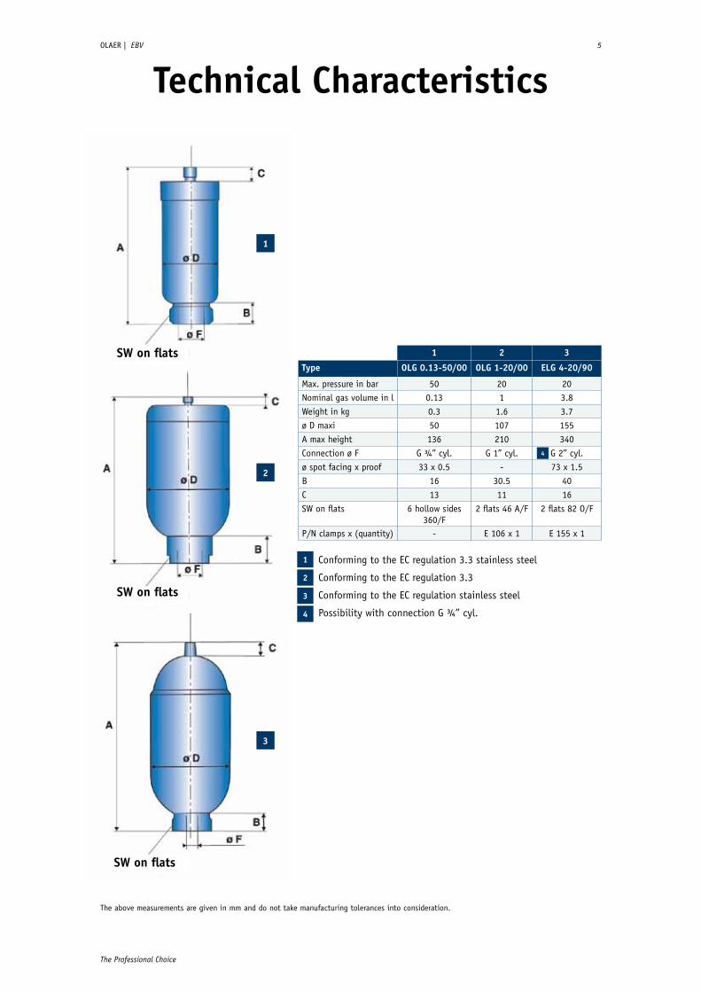
Technical Characteristics
Conforming to the EC regulation 3.3 stainless steel
Conforming to the EC regulation 3.3
Conforming to the EC regulation stainless steel
Possibility with connection G ¾” cyl.
1
2
3
4
1 2 3
Type OLG 0.13-50/00 OLG 1-20/00 ELG 4-20/90
Max. pressure in bar 50 20 20Nominal gas volume in l 0.13 1 3.8
Weight in kg 0.3 1.6 3.7
ø D maxi 50 107 155
A max height 136 210 340
Connection ø F G ¾” cyl. G 1” cyl. G 2” cyl.
ø spot facing x proof 33 x 0.5 - 73 x 1.5
B 16 30.5 40
C 13 11 16
SW on flats 6 hollow sides 360/F
2 flats 46 A/F 2 flats 82 O/F
P/N clamps x (quantity) - E 106 x 1 E 155 x 1
4
The above measurements are given in mm and do not take manufacturing tolerances into consideration.

Technical Characteristics6 OLAER | EBV
www.olaer.com
EBV RANGE FROM 0.5 TO 5 LiTERs - sTANdARd CONsTRuCTiON
Type
Effe
ctiv
e Ga
s vo
l. L
iter
s
Wor
k pr
essu
reba
r
Wei
ght
inKi
lo
Clam
ps x
(qua
ntit
y)
O-ri
ngø
int
x ø
tore
supp
ort
brac
ket
Fitt
ings
&
Flan
ges
dimensions in mm
Amax
height
B C ødmax
ød øH øFconnection
EBV 0.5-50/00* 0.5 50 2.2 E95
54x3
-
consultpage 9
243 52 28 90 16 68 G 2”cyl.
EBV 1-80/00* 1 80 5 E114 CE 89 310 47 66 116 22.5 68 G 2”cyl.
EBV 2.5-80/90 2.3 80 9 E114 CE 89 482 47 66 116 22.5 68 G 2”cyl.
EBV 5-80/90 5 80 16 E114 CE 89 805 47 66 116 22.5 68 G 2”cyl.
sTAiNLEss sTEEL CONsTRuCTiON
* complying to the regulation EC 3.3
Type
Effe
ctiv
e Ga
s vo
l. L
iter
s
Wor
k pr
essu
reba
r
Wei
ght
inKi
lo
Clam
ps x
(qua
ntit
y)
O-ri
ngø
int
x ø
tore
supp
ort
brac
ket
Fitt
ings
&
Flan
ges
dimensions in mm
Amax
height
B C ødmax
ød øH øFconnection
EBV 0.5-40/00* 0.5 40 2.1 E95
54x3
-
consultpage 9
240 54 29.5 90 16 70 G 2”cyl.
EBV 1-40/00* 1 40 2.8 E106 CE 89 308 52 75 109 22.5 70 G 2”cyl.
EBV 2.5-40/90 2.5 40 3.2 E106 CE 89 484 51 75 109 22.5 70 G 2”cyl.
EBV 5-40/90 5 40 6.2 E106 CE 89 867 51 75 109 22.5 70 G 2”cyl.
* complying to the regulation EC 3.3
The above measurements are given in mm and do not take manufacturing tolerances into consideration.
Fittings & Flanges page 9Fittings & Flanges page 9
O’Ring

OLAER | EBV 9
The Professional Choice
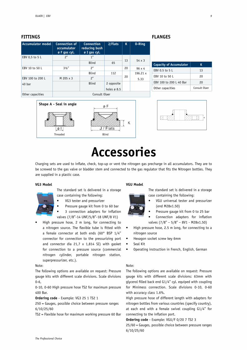
FiTTiNGsAccumulator model Connection of
accumulator ø F gas cyl.
Connectionreducing bush
ø i gas cyl.
J/Flats K O-Ring
EBV 0,5 to 5 L 2” 1”13 54 x 3
Blind 65
EBV 10 to 50 L 3½” 2“ 20 96 x 4Blind 112
20196.21 x
5.33EBV 100 to 200 L
40 bar
M 205 x 3 2”
Blind 2 opposite
holes ø 8.5
Other capacities Consult Olaer
Capacity of Accumulator K
EBV 0.5 to 5 L 13
EBV 10 to 50 L 20
EBV 100 to 200 L 40 Bar 20
Other capacities Consult Olaer
shape A - seal in angle
Threaded Blind
FLANGEs
Accessories
VG3 ModelThe standard set is delivered in a storage case containing the following:• VG3 tester and pressurizer• Pressure gauge kit from 0 to 60 bar• 3 connection adapters for inflation valves (7/8”-14 UNF/5/8”-18 UNF/8 V1)
• High pressure hose, 2 m long, for connecting to a nitrogen source. The flexible tube is fitted with a female connector at both ends (60° BSP 1/4’’ connector for connection to the pressurizing port and connector dia 21,7 x 1,814 SI) with gasket for connection to a pressure source (commercial nitrogen cylinder, portable nitrogen station, superpressurizer, etc.).
Note:The following options are available on request: Pressure gauge kits with different scale divisions. Scale divisions 0-6,0-10, 0-60 High pressure hose TS2 for maximum pressure 400 Bar.Ordering code - Example: VG3 25 1 TS2 1250 = Gauges, possible choice between pressure ranges6/10/25/60TS2 = Flexible hose for maximum working pressure 60 Bar
VGu ModelThe standard set is delivered in a storage case containing the following:• VGU universal tester and pressurizer (end M28x1.50)• Pressure gauge kit from 0 to 25 bar• Connection adapters for inflation valves (7/8’’ – 5/8’’ – 8V1 - M28x1.50)
• High pressure hose, 2.5 m long, for connecting to a nitrogen source
• Hexagon socket screw key 6mm• Seal Kit• Operating instruction in French, English, German
Note:The following options are available on request: Pressure gauge kits with different scale divisions: 63mm with glycerol filled back end G1/4’’ cyl. equiped with coupling for Minimess connection. Scale divisions 0-10, 0-60 with accuracy class 1.6%.High pressure hose of different length with adapters for nitrogen bottles from various countries (specify country), at each end with a female swivel coupling G1/4’’ for connecting to the inflation port.Ordering code - Example: VGU/F 0/20 7 TS2 325/60 = Gauges, possible choice between pressure ranges 6/10/25/60
Charging sets are used to inflate, check, top-up or vent the nitrogen gas precharge in all accumulators. They are to be screwed to the gas valve or bladder stem and connected to the gas regulator that fits the Nitrogen bottles. They are supplied in a plastic case.
10 OLAER | EBV
www.olaer.com
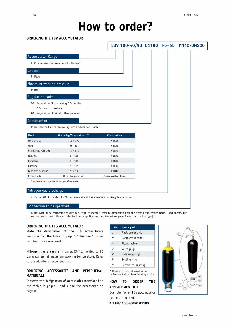
How to order?ORdERiNG THE EBV ACCuMuLATOR
Fluid Operating Temperature °C* Construction
Mineral oils -15 + 100 01125
Water 0 + 60 03325
Diesel fuel (Gas Oil) - 5 + 115 01130
Fuel Oil -5 + 115 01130
Kerosene -5 + 115 01130
Gasoline -5 + 115 01130
Lead free gasoline -20 + 130 01180
Other fluids Other temperatures Please contact Olaer
Accumulator Range
in liters
in Bar
Volume
Maximum working pressure
EBV 100-40/90 01180 Po=5b PN40-dN200
EBV European low pressure with bladder
00 : Regulation EC complying 3.3 for the
0.5 L and 1 L volume
90 : Regulation EC for all other volumes
Regulation code
to be specified as per following recommendations table
Construction
Nitrogen gas precharge
in Bar at 20 °C, limited to 20 Bar maximum at the maximum working temperature
Connection to be specified
Blind: with blind connector or with reduction connector (refer to dimension I on the overall dimensions page 9 and specify the connection) or with flange (refer to th eflange line on the dimensions page 9 and specify the type).
* Accumulators operation temperature range
* These parts are delivered in the replacement kit with explanatory notice
item spare parts
1 Replacement kit
2* Complete bladder
3* Filling valve
4* Valve plug
5* Retaining ring
6* Sealing ring
7* Perforated bushing
ORdERiNG THE ELG ACCuMuLATORState the designation of the ELG accumulators mentioned in the table in page 4 “plumbing” (other constructions on request)
Nitrogen gas pressure in bar at 20 °C, limited to 20 bar maximum at maximum working temperature. Refer to the plumbing sector section.
ORdERiNG ACCEssORiEs ANd PERiPHERAL MATERiALsIndicate the designation of accessories mentioned in the tables in pages 8 and 9 and the accessories on page 8.
HOW TO ORdER THE REPLACEMENT KiTExample: For an EBV accumulator
100-40/90 01180
KiT EBV 100-40/90 01180

OLAER | EBV 11
The Professional Choice
installation
Regulation Extract from European legislation. Directive 97/23/ EC is applicable from 29-11-1999 and mandatory from 29-05-2002. Decree 99-1046, which applies to new machinery and the ministerial order of 15-03-2000, which applies to the operation of all machinery, transposed the directive into French domestic legislation.
WHAT YOu NEEd TO KNOW
Directive 97/23/ EC is applicable fom 29-11-1999
and mandatory from 29-05-2002. Decree 99-1046,
which applies to new machinery and the ministerial
order of 15-03-2000, which applies to the operation
of all machinery, transposed the directive into French
domestic legislation.
• Free movement of machinery within the European
Union.
• Group 2 fluid accumulators whose V ≤ 1 L and PS ≤
1000 bar are not entitled to bear EC marking.
• The EC marking should be accompanied by the
identification number of the notified authority.
EC type accumulators are delivered
with instructions for operation and
a declaration of conformity.
Olaer designs and manufactures
hydro-pneumatic accumulators
for use in all countries and which
comply with national regulations
in force as ASME / SELO...
iT is sTRiCTLY FORBiddEN TO• Weld, screw or rivet anything onto the
accumulator body.
• Operate in any way that may alter the mechanical
properties of the accumulator.
• Use the accumulator for construction purposes.
(No stress or loading)
• To modify the accumulator without prior approval
from the manufacturer.
GAs FiLLiNGFor safety reasons, use only pure nitrogen, minimum
99.8% volume. the pre-charge pressure is less than 20
Bar at the maximum operating temperature or is limited
to the pressure of the shell if < 20 Bar. Your local Olaer
office can calculate the correct pre-charge pressure for
your application. Olaer offers a range of devices for
checking nitrogen pressure as well as pre-charging
accumulators. Please note that various adaptors are
required to interface with different accumulator filling
valves and nitrogen (N2) cylinder connections
throughout the world.
The part number defines the accumulator and the material
construction. Information contained on the labeling/
manufacturer’s plate:
• Olaer logo
• Product description
• Date or year of manufacture
• Reference information of the accumulator
• Allowable temperature range of the accumulator
•
Additional information on certain models:
• Warning messages and safety instructions
(“Danger”, ”Use nitrogen only” or similar message)
• Maximum inflation pressure P0 max in bar
• Allowable pressure amplitude P max in bar
• Fluid group (1 or 2 according to the Directive
97/23/EC)
• Total dry mass in kilogram
Position: Preferably vertical (liquid connection downwards) to horizontal, depending upon application. If the
accumulator is installed in any position other that vertical with fluid port down, contact Olaer. The accumulator could
have reduced volumetric efficiency and Olaer can help you to take these factors into account.
Mounting: A 200mm clearance is required above the accumulator to allow for gas charging. Each accumulator is
delivered with a user instructions leaflet. Ensure that the pipes connected directly or indirectly to the accumulator are
not subjected to any abnormal force, Ensure that the accumulator cannot move, or minimize any movement that may
occur as a result of broken connections. Olaer clamps and brackets are designed for this purpose (and can be supplied
as optional extras). The accumulator must not subjected to any stress or load, in particular from the structure with
which it is associated. Contact Olaer in case of mounting on the movable structures.

The Professional Choice
www.olaer.com
- in Fluid Energy Management
Global perspectiveand local entrepreneurial flair
Olaer is a global player specialising in innovative,
efficient system solutions for temperature optimisation
and energy storage. Olaer develops, manufactures and
markets products and systems for a number of different
sectors, e.g. the aircraft, engineering, steel and
mining industries, as well as for sectors such as oil and
gas, contracting and transport, farming and forestry,
renewable energy, etc.
All over the world, our products operate in the most
diverse environments and applications. One constantly
repeated demand in the market is for optimal energy
storage and temperature optimisation. We work at a
local level with a whole world as our workplace – local
entrepreneurial flair and a global perspective go hand
in hand.
Our local presence, long experience and a wealth of
knowledge combine with our cutting-edge expertise
to give you the best possible conditions for making a
professional choice.
Copy
right
© 2
009
OLAE
R
Copy
right
© J
anua
ry 2
011
OLAE
R - T
he in
form
atio
n in
this
bro
chur
e is
sub
ject
to c
hang
e w
itho
ut p
rior n
otic
e.