Embed Size (px)
Citation preview

1.002
Access Control Panel
U-Prox IP300
Installation and programming manual

http://u-prox.com
2
About this document
This manual covers installation, adjustment and utilization of U-Prox IP300
(hereinafter panel) access control panel. Read this manual carefully prior to installing
the system.
Characteristics, Intended use and parameters of the panel are described in the
section "Summary". Section "Terms" provides an explanation of terms found in this
document.
The look of the panel, the pins and the mode of work are described in the
"Description section". Order of installation, adjustment of external devices and
panel configuration are described in "Working with the device" section.
Technical support
To get warranty and technical support you can apply to authorized service centers,
situated on the territory of countries, enlisted in the warranty card.
Warranty and technical support are performed on the territory of the country, where
the customer applied for warranty or free service.
Technical information is available on the system website
www.u-prox.com
Attention! Read this manual carefully prior to installing the system.
Installation, adjustment and utilization of panel is allowed only to persons or
organizations with the appropriate authority from the manufacturer
http://u-prox.com
3
Contents Brief description of the panel ......................................................................................................... 4
Intended use .............................................................................................................................. 4 Characteristics ........................................................................................................................... 5
Terms ............................................................................................................................................ 6 Description and operation .............................................................................................................. 8
Panel ......................................................................................................................................... 8 Terminals ............................................................................................................................... 9 Sound and light panel ............................................................................................................ 9
Panel operation ....................................................................................................................... 10 “Normal” mode ..................................................................................................................... 10 "Alarm" Mode ....................................................................................................................... 11 "Free Pass” Mode ................................................................................................................ 11 "Blocking" Mode ................................................................................................................... 12 RF ID properties (cards) ....................................................................................................... 12 Variants of Use and modes of output ................................................................................... 13 The communicator ............................................................................................................... 13 Global antipassback ............................................................................................................. 17
How to work with the device ........................................................................................................ 20 Connection procedure ............................................................................................................. 20 Installation recommendations .................................................................................................. 21 Installing Panel ........................................................................................................................ 21 Connecting an external reader ................................................................................................. 22 Connecting Loop Control ......................................................................................................... 23
Request to Exit button (RTE) ............................................................................................... 23 Door Contact ........................................................................................................................ 24 Combined Loop- RTE and Door Contact .............................................................................. 25 Loop "Control 220 and Battery" ............................................................................................ 25 Actuators ............................................................................................................................. 26 Electric locks ........................................................................................................................ 26
Connection .............................................................................................................................. 28 Wired computer network (Ethernet) ...................................................................................... 28 Wireless computer network (Wi-Fi) ...................................................................................... 29
Panel programing .................................................................................................................... 31 Maintenance ............................................................................................................................ 32
Factory reset (before installation) ......................................................................................... 32 Factory reset (after installation) ............................................................................................ 32 Switching to programming mode .......................................................................................... 32 Replacing the device firmware ............................................................................................. 32
Factory settings ....................................................................................................................... 32

http://u-prox.com
4
Brief description of the panel U-Prox IP300 control panel - a device designed to control access to residential and
business premises, for pass time and events logging and analysis, including
personnel time attendance.
The default modification panel has built-in proximity card reader (ASK and FSK RF
IDs) and keyboard.
The MF modification panel has built-in card reader ISO14443A (Mifare® Standard,
Mifare® Hi-Memory, Mifare® Ultralight) and keyboard.
U-Prox IP300 processes the information received from the reader (readers), and
controls actuator (e.g. a lock) with the built-in relay.
Panel has two End-of-line supervised inputs.
The panel can work offline or as part of the network. To add it to Access Control
network, Ethernet (wired computer network) or Wi-Fi (wireless computer network)
interfaces are used.
The network settings of the control panel are programmed via a standard USB port
(Micro USB B).
Panel U-Prox IP300 has advanced hardware capabilities and intellectual functions to
control a single door with one built-in reader (single-sided door) or two readers
(double-sided door). Having a large amount of non-volatile memory U-Prox IP300 is
an access control system that provides for access control in variable establishments
in small offices as well as on large enterprises with number of employees up to
31768 and up to 1,000 visitors.
Thoroughly elaborated technical and design solutions, the ability to connect external
reader, communication over a computer Ethernet network or wireless Wi-Fi, non-
volatile memory and the clock, protecting the communication ports and port reader
for short circuit, over-voltage and reverse polarity - all allows to use the panel to build
a variety of Access Control Systems (ACS) - from the system for a small office to the
entrance of a large enterprise.
Intended use
Panel U-Prox IP300 is designed for operation in access control systems (ACS) of
diverse scale in small offices as well as on large enterprises. Panels are connected
in ACS via computer network Ethernet or wireless Wi-Fi.
The panel provides access to one room with the ability to control entry and exit as
well as an alarm system of rooms connected with this access point. In the case of
simultaneous control of entry and exit from the rooms function " Antipassback" is
provided (prohibition of re-runs).

http://u-prox.com
5
Characteristics
Built-in card reader:
o Default: with support for ASK and FSK identifiers.
o MF Modification: ISO14443A - Mifare® Standard, Mifare® Hi-
Memory, and Mifare® Ultralight identifiers
Programming of readers indication
Reading distance: up to 50 mm
Current consumption from 12V power source (off load), max 160 mA
Amplitude ripple of DC power supply, no more than 500 mV
External reader may be connected to the U-Prox IP300. It should be
U-Prox series
Two End-of-line supervised inputs
Built-in Request to Exit button
One relay (contact NO, NC, COM) 1 A @ 24 V
One USB port to configure the network settings (for connection to the ACS
server )
Port Ethernet (4 wire) 10/100 Mbps.
Wi-Fi device. Support WEP/WPA/WPA2.
The complete configuration is done using ACS software via a computer
network
Antipassback
Real-time clock (Door Time)
Non-volatile memory:
RF IDs 31768
Events 47000
Time zones 255
Weekly schedules 255
Holidays 255
Temporary RF IDs 1000
Overall Unit Dimensions - 119.4 x65, 4x20, 4 mm
Weight Panel - 0.2 kg
Climatic version - UHL 4.2 GOST 15150-69 in the range of ambient
temperatures from 0 to +55оC
Relative humidity up to 80% without condensation

http://u-prox.com
6
Terms Identifiers
In access control systems each user has a unique RF ID. Identifiers can take the
form of a plastic card, key FOB etc.
Reader
The information on the identifiers is read with READERS, connected to the ACS
control panel. There are several types of RF IDs and readers for them. It is essential
that reader and control panel use the same interface. Only U-Prox series readers
may be connected to the U-Prox IP 100 control panel.
PIN (Personal Identification Number)
Some readers have built-in keypad. Keypads may be used for PIN entering. It can
be both self-dependant or used as an additional code to user RF ID. When PIN is
programmed as additional code, reader waits for PIN entering after RF ID is read-
out.
Access point
Access point is a logical concept of the access control system implying control of
passing through a door in one direction. It consists of reader, access control panel
(or its part), door supervision devices (like door contact, RTE button etc.) and door
locking device. For instance, the turnstile with two-way passes has two Access
points – one for entrance and the other one for exit, door of this type is called
double-sided door. A door with a reader on one side has only one Access point –
Entry point, and it is called single-sided door\
Direction of passage
Passageway - is a logical unit of ACS, controlling passage through the access point
in one direction. It includes reader, access control panel (or part of access control
panel), actuator. So, tourniquet with double-sided control has two passageways, and
the door, having single-sided reader - only one passageway. Access point, which
consists of two passageways, is called double-sided, and the point of access, which
consists of one direction of passage - single- sided.
RTE (request to exit)
To exit from the premises with a single-sided door, a button wired to control panel is
used. This button is called RTE (request to exit) button. If someone opens a door
otherwise than pressing RTE button – by re-energizing locking device, opening lock
with a key etc., "Door Forced Open" event arises. RTE button may be used for
remote door opening as well.
Door Contact
A properly designed ACS has to supervise door status (opened or closed): magnetic
door sensor, sensor of the turnstile rotor position, inductive sensor of the road
barrier, etc. This ensured that the system prevents situations when several users
access the door with one RF ID or door left open after user’s access and so on.

http://u-prox.com
7
For these purposes the magnetic door sensor, the turnstile rotor position sensor and
the position sensor of boom barrier are connected to the input of panel. The input
used to connect the sensors, is called the input of the door contact.
Antipassback
Antipassback function is implemented in access control panels to prevent the
situation when user gives his RF ID to another person after passing into the
premises. If this function is on, control panel tracks an RF ID position – inside or
outside the premises. On any attempt to pass in the same direction twice the panel
denies access and stores “Access Denied, Antipassback” event into the Log.
Antipassback function can be set on only in case of the double-sided door control.
Global antipassback
Tracking of identifier movement through controlled access points. The object is
divisible by access areas. Passage into areas of access is possible through multiple
access points. Access control panels denied access when trying to re-pass,
unauthorized use of the identifier in these areas. When access is denied door control
panels and the main antipassback panel generate message GLOBAL
ANTIPASSBACK: Access Denied.
Door time
If door sensor is open, corresponding access point goes into alarm. Alarm is not
invoked, if contact is opened during Door Time interval. This interval starts when
access is granted and lasts for the programmed time or terminates on opening and
subsequent closing of door contact.
Code matching attempt
Control panels can activate alarm on attempt of a code (or RF ID) matching. Code
matching is considered when invalid code (or RF ID) is entered several times
successively. Valid code entering clears the counter. This function switching On and
number of code entrances are subjects of programming.
Schedules
Date and time of valid access are indicated when setting user access rights. Control
panel stores up to 250 time zones.
250 week schedules can be combined from these time zones.
Moreover, control panel can store up to 250 holidays, which happen once a year.
Time zones
Time zones are a part of schedule. This is a way to organize a range of days and
times and associate it with access levels.
Time zones are utilized by the application to validate, authorize, or perform various
functions based on schedules.

http://u-prox.com
8
Downloading
Control panel is to be downloaded after all parameters are set – modes of inputs,
outputs, access rights and others. During downloading parameters are rewritten into
access control panel.
Description and operation
Panel The look of the access control panel is shown in Fig. 1 and 2.
Fig. 1. U-Prox IP300 panel
Fig. 2. U-Prox IP300 components
3
4
2
1
1. Panel enclosure 2. RTE 3. LED 4. Keypad
1 1. The top cover of the
panel
2. Contol panel
electronics, injected
with polyuretane resin
3. The back plate of corps
with terminal block for
commutation
4. The backplate
connector
5. Backplate's fixing
screws
6. USB port (micro USB B)
7. Fixing screw
2
3
5
6
7
4

http://u-prox.com
9
Terminals
Contact Name Purpose
NC normally closed
Relay contacts COM General
NO normally disclosed
+E +12 V
Power
Connection to the power supply,
connection of an external reader
GND GND Connection to the power supply,
connection of an external reader, common
for input loops
DT0 D0 (Data 0) Connection of an external reader
DT1 D1 (Data 1)
Z1 Вход 1
Terminals for Loop Z2 Вход 2
GND общий
Разъем Ethernet
ORW TX+
Connecting Ethernet cable
GN TX–
GNW RX+
GN RX–
Разъем USB
USB Micro B USB разъем Used for the initial configuration of the
network settings
Sound and light panel
Yellow LED:
Standby mode (periodic blinking): o 1 short pulse once per second - communication - Working in notification
mode, connection normal; o 2 short pulse once per second - communication - Working in the
notification mode, no connection frequent blinking - downloading data from the server uploading mode:
o LED is on for 5 seconds - the detection of removed top cover, uploading mode start
o frequent blinking - waiting in uploading mode (with removed top cover), this indication means that the attempt to upgrade the firmware failed
o 6 short beeps - successful upgrade of firmware o 2 short beeps - uploading mode exit
6 short beeps (with shorted pins D0 and D1) – Factory reset .
Green LED 1 - Link (next to the jack Ethernet):
On - Ethernet cable is OK
Green LED 2 - Eth. Activity (next to connector USB)
Frequent blinking - Data Exchange
http://u-prox.com
10
Panel operation
The panels supplied unloaded with factory settings below in document. In this state,
the indicators of readers and the yellow LED on the panel flashes once per second.
To make the panel work in access control system (ACS) you have to upload a
network setting using the "Configurator" software and USB port.
Attention! All inputs should be terminated with resistors (supplied).
If no inputs are triggered panel goes to mode “Normal” after uploading the
configuration.
The panel can supervise one door with one or two access points. There are four
modes of access point: " Normal”, “Alarm", "Blocking" and "Free Pass." "Free Pass"
has the highest priority. If no inputs are broken Panel goes to mode "Normal" after
uploading the configuration.
Panel can supervise one door with one or two access points. There are four modes
of access point: "Normal”, “Alarm", "Blocking" and "Free Pass." Mode "Free Pass"
has the highest priority, as this mode is activated in the event of a fire, followed by
modes of "Blocking", "Alarm" and "Normal” in decreasing order of priority.
“Normal” mode
This is the main mode of the panel. In this mode, the panel grants or denies access
to RF ID owners.
In “Normal" mode the readers blink red.
Passing after entering RF ID
To pass through user enters contactless RF ID to the reader. If RF ID is registered
and the passage is granted, access point opens (the panel activates the actuator).
The reader LED becomes green.
Passing after entering RF ID and PIN code
On entering enrolled RF ID, panel tests whether PIN code is required, and, if
required, waits for entering PIN code. After entering the correct PIN code, AP opens
(the actuator is activated).
The reader LED becomes green.
Passing upon Request to Exit (remote opening of doors)
Exit from premises with single-sided door or passing of users is granted upon
pressing Request to Exit (RTE). Pressing and releasing of RTE AP opens the door
(actuator is activated). The reader LED becomes green.
Access denial upon entering RF ID
Access may be denied to RF ID owner due to the following reasons (the reader LED
is red):
cards (RF IDs) and schedules are not loaded in the panel (light off)
card is not enrolled in the panel (for 1 second buzzer is on and LED is red )
card term expired (for 1 second buzzer is on and LED is red )
RF ID passed out of schedule (for 1 second buzzer is on and LED is red)

http://u-prox.com
11
attempt to re-pass when "Antipassback" is on (for 1 second buzzer is on
and LED is red)
entered RF ID is marked as lost or Blocking (for 1 second buzzer is on and
LED is red)
the panel is in "Alarm" mode (LED is constantly on and red)
the panel is in "Blocking" mode (LED flashes red and yellow in turn)
Pass count is exhausted for the temporary card (visitor).
"Alarm" Mode
In "Alarm" mode the reader indicator is constantly red. Depending on the
programmed functions Access point goes into mode "Alarm" in case of
unauthorized passage (Door Forced Open), opening of panel cover, entering RF ID
recorded as lost, if AP is open too long (open time AP is exceeded), and in case of
RF ID matching attempt.
In "Alarm” mode panel activates outputs, programmed as ALARM and SIREN.
"Alarm" output remains activated till “Alarm" mode is turned off. For output "SIREN",
siren time is programmable.
If Access point is in “Alarm mode", passage is prohibited. Access point may be
opened by pressing RTE.
To exit from the "Alarm" mode pass the ID with "Disalarm" attribute or by command
from the computer.
"Free Pass” Mode
There are circumstances when you need to open access points for free passage of
people, such as in the case of fire, earthquake or in other emergency. For this case,
the panel has "Free Pass" mode.
In "Free Pass” Mode LED of reader flashes green and yellow.
The access point goes into "Free Pass" Mode after the command of operator from
the computer or after the loop violation (break or shortage) programmed as FREE
PASS. The access point is in "Free Pass" Mode for as long as the loop FREE PASS
is broken or until the command from the computer comes (while the loop is broken,
command from the computer will not work).
The panel allows to configure the function of loop "Free Pass" for access points A, B,
or for both access points (A + B).
As long as access point is in "Free Pass" mode, the lock is held in open position, the
panel stores a log event "Access granted" on presentation of RF ID code regardless
of the antipassback state of, schedules, etc. It is used to control the presence of
personnel on the premises in case of an emergency.
To ensure "Free Pass" mode when using locking devices with mechanical re-
platoon you must control access point state. Locking devices with mechanical re-
platoon can be unlocked with current pulse and remain unlocked until access point is
not opened. While closing door, locking device goes into a closed state. Panel in
"Free Pass" mode tests the door contact. Each closing of door again gives unlocking
signal to the door.

http://u-prox.com
12
"Blocking" Mode
If it is necessary to deny access to AP to all users of the system, the panel switches into “Blocking" mode. If AP is in “Blocking" mode, the passage is granted only to owners of RF IDs with the sign "Security Service". AP cannot be opened by pressing RTE.
In "Blocking" mode LED is alternately flash red and yellow
Access point goes into “Blocking" mode after the operator command from the
computer or after loop violation designated as BLOCKING. Access point is in
“Blocking" mode for as long as the loop is violated or until the command from the
computer (while the loop is broken, command from the computer will not work).
Panel allows to configure loop function “Blocking" for access point A, B, or for both
access points (A + B).
RF ID properties (cards)
Code (RF ID card code)
Each card has a unique code which is set at the time of its manufacture. It consists
of 10 hexadecimal digits.
PIN-code
Additional code is assigned to the card. It consists of no more than six decimal digits.
It can be used together with readers that have a built-in keyboard.
Enter PIN code with the reader's keypad and press '#' key. Always enter PIN code
AFTER the card pass. If PIN-code is correct, panel unlocks access point and grants
access. Otherwise, panel generates a warning signal, and records "Invalid PIN-
code" event into the log. Door remains closed.
Validity (of Card)
Card Validity expiration date.
Alarm Cancel
Passing the card to door reader, when the door is in "Alarm" state, panel registers
event "Alarm cancelled" and puts the door to Normal mode. If the card that has no
right to cancel the “Alarm” is passed, the door will remain in the same state. “Access
denied. Alarm Status" event recorded into the log.
Security Service
Security Service mark gives the right of access to a Blocking door.
When the ordinary card is passed if door is in "Blocking” Mode, "Access denied.
Blocking state” event recoded. Card with attribute “Security Service" pass. If the card
is valid and has access right at the moment, the panel gives access and event
“Access granted. Blocking state» is registered.
VIP
Access right to pass always everywhere, except through Blocking door.
VIP card may be assigned any schedule, Antipassback and validity period is NOT
applied to it. The card may have PIN code

http://u-prox.com
13
If the door is in “Blocking state", access is denied for RF ID with this attribute
checked.
Antipassback is off
Access right without considering Antipassback Mode.
Access is granted regardless of the direction of the previous access, but according
to the schedule and other attributes designated to the Card
Variants of Use and modes of output
All panel outputs can be programmed in any order for several functions: Blocking,
Siren, Alarm, Programmable output. In addition, there is programmable operation
mode for each output: start-stop (output remains active until the corresponding
command is present, for example, during the time until the panel is in "Alarm" Mode),
impulse (the output is activated for the programmed time), trigger mode (on the first
event the output is activated, on the following is off, etc.), continuous.
The communicator
U-Prox IP300 panels operates automatically - after downloading data from the
server, it processes the card passed according to its access rights, grants or denies
access and sends event rehire to the ACS server.
Panel communicator operates in the notification mode. If there is event (passage,
violation of input) event report message is send ACS server.
U-Prox IP300 panel can be connected to a computer network via wired connection
(Ethernet) or via wireless network. This ensures work within local network (see
Figure 3) or via the Internet (see Fig. 4), that allows to build distributed access
systems of any size.
Fig. 3. An example of a local network of mixed type (Ethernet and Wi- Fi)

http://u-prox.com
14
Fig. 4. An example of a distributed network
For setting common network of central office and branches for extra protection using
VPN technology is recommend. To provide backup communication channels use
routers with two dissimilar channels of access to the Internet.
Working with multiple Wi-Fi access points support reserving a wireless
communication channel (main and backup) - see Figure 5.
Fig. 5. Working with multiple Wi-Fi access points
http://u-prox.com
15
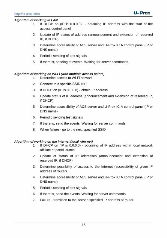
Algorithm of working in LAN
1. If DHCP on (IP is 0.0.0.0) - obtaining IP address with the start of the
access control panel
2. Update of IP status of address (announcement and extension of reserved
IP, if DHCP)
3. Determine accessibility of ACS server and U-Prox IC A control panel (IP or
DNS name)
4. Periodic sending of test signals
5. If there is, sending of events. Waiting for server commands.
Algorithm of working on Wi-Fi (with multiple access points)
1. Determine access to Wi-Fi network
2. Connect to a specific SSID № 1
3. If DHCP on (IP is 0.0.0.0) - obtain IP address
4. Update status of IP address (announcement and extension of reserved IP,
if DHCP)
5. Determine accessibility of ACS server and U-Prox IC A control panel (IP or
DNS name)
6. Periodic sending test signals
7. If there is, send the events. Waiting for server commands.
8. When failure - go to the next specified SSID
Algorithm of working on the Internet (local wire net)
1. If DHCP on (IP is 0.0.0.0) - obtaining of IP address within local network
affiliate at panel launch
2. Update of status of IP addresses (announcement and extension of
reserved IP, if DHCP)
3. Determine possibility of access to the Internet (accessibility of given IP
address of router)
4. Determine accessibility of ACS server and U-Prox IC A control panel (IP or
DNS name)
5. Periodic sending of test signals
6. If there is, send the events. Waiting for server commands.
7. Failure - transition to the second specified IP address of router.

http://u-prox.com
16
Algorithm of working on the Internet (WLAN Wi-Fi)
1. Determine accessibility to Wi-Fi network
2. Connecting to specified SSID № 1 If DHCP - obtain IP address within local
network affiliate at panel launch
3. If DHCP on (IP is 0.0.0.0) - obtain IP address
4. Update of status of IP addresses (announcement and extension of
reserved IP, if DHCP)
5. Determine possibility of accessing the Internet (access to given IP
addresses of routers)
6. Determine accessibility of ACS server and U-Prox IC A control panel (IP or
DNS name)
7. Periodic sending of test signals
8. If there is, send the events. Waiting for server commands.
9. Failure - transition to the second IP address of specified router
10. Repeated failure - go to the next specified SSID
Server addresses automatic configuration for control panel
The use of the existing computer network infrastructure, standard network protocols
(DHCP for instance) allowed to provide the “plug-and-play” principle. The mode of
the automatic server address configuration in the panels eases the wireless lock
system deployment significantly.
Fig. 6. System deployment
The algorithms for operation on each step described below

http://u-prox.com
17
1. Panel checks for DHCP mode ON (panel address 0.0.0.0) or static IP
2. If DHCP mode is ON, the dynamic IP address obtain routine will start
3. The panel automatic configuration mode starts if the access control system IP address (IP or DNS name) is not set:
a. Panel sends data packages announcing access control system
server about itself as a new device in the local network
Despite it is broadcast announcement, it is limited with single
range local network and active network equipment. That’s why
the IP addresses of the access control system server are to be
set manually for networks with sophisticated topology.
b. The system will warn operator after the receiving of the data
package from the new panel. Operator must add panel to the
system database (DB).
c. After the panel added to the DB it receives the answer from the
access control system server. The address of the access control
system server recorded into the control panel and it stops to
broadcast.
d. Operator has to upload panel after its adjustment recorded into
the DB. Panel becomes associated to the certain access control
system server, eliminating panel control capture with another
system.
Return panel to the factory settings to eliminate the panel
association to the system
e. In the case of access control system server IP address change
panel will initiate the automatic configuration routine, but the data
exchange will be possible with previously connected system only.
Global antipassback
U-Prox IP300 control panel can operate in a system of global antipassback. The
main controller U-Prox IC A tracks the location of a person on the fact of its passage
through the access point. U-Prox IC A receives data about the passages from
control panels U-Prox IP400, NDC F18 IP, U-Prox IP100, U-Prox IP300.
The basis of the global antipassback is the zoned antipassback. The facility is
divided into rooms - zones of access or areas. With this division the entrance to
another area is exit from the previous one, and the passage in the area is possible
through various access points.
Antipassback control panel receives data from the access control panels and tracks
the movement of personnel from area to area . Also can be tracked the location of
the person who has multiple IDs (See Figure 7).

http://u-prox.com
18
Fig. 7. Allocation of access areas
Initially an employee has the location "unspecified". After the first presentation ID to
a reader's location
The location "unspecified" is assigned when registering a new employee, or after the
system operator command "location reset" of person is fixed by U-Prox IC A.
With the use of global antipassback it is possible to suppress passback, using
duplicate card for infiltration (sudden appearance inside), transferring the ID to
another person, etc (See Figure 8).
Fig. 8. Tracking the violations

http://u-prox.com
19
In case of lost communication with the access control panels, forced entry, free
pass, etc. U-Prox IC A merges access areas together , considering that the
personnel may be both there and there.
After restoring the normal state of access point or communication with the control
panels, areas will be unmerged (See Figure 9).
Fig. 9. Merging access zones
U-Prox IP400, U-Prox IP100, U-Prox IP300, NDC F18 IP access control panels can
be configured to two variants of behavior in case communication lost with U-Prox IC
A:
Not to pass anyone;
Pass all according to the rules of the local antipassback
The requirements for U-Prox IC A adjusting:
Control panel must have static address (IP or DNS)
The requirements for U-Prox IP300,U-Prox IP300 ,U-Prox IP400, NDC F18 IP adjusting:
Only control panels with double-sided doors (entrance and exit on
presentation of ID) can be involved in global antipassback.
In configuraion server address # 1 has to be the ACS server address.
In configuraion server address #2 has to be the addrees of U-Prox IC A
In the U-Prox IP software must be enabled antipassback mode "General"
for door
For each access control panel must be specified master antipassback
control panel and reaction to the loss of communication with him.
U-Prox IP400, U-Prox IP100, U-Prox IP300, NDC F18 IP control panels deliver
events to two addresses at the same time. First one is ACS server's address, to
display and store events in a database program. The second one is address of U-
Prox IC A. Antippassback control panel sends answer with command to denу or
grant access.
After ID presentation the delay in granting or denial of access may be up to 1 seconds, depending on the topology and bandwidth of the computer network

http://u-prox.com
20
How to work with the device The panel is delivered in a small plastic
case with subsequent sealing Overall
dimensions are shown in Fig. 10.
Connection procedure
1. Before installation do initial setup
of panel (that specifies settings of
network parameters) with utility
"Configurator" via USB Port
2. In the place of installation of the
panel do preparing - mark and
drill the holes (see Installing
panel)
3. Run the cable lead from the power
supply
4. Run the cable lead from the actuator
(lock)
5. Install external reader and run their
cables (if necessary)
6. Run loops from sensors / buttons
7. Run the cable lead-Ethernet (if necessary)
8. Run the wire commutation of power supply, lock, reader, inputs of the panel
with the loops in accordance with the sections below (recommended using
the back box)
9. Perform installation of the Ethernet cable into the connector terminal blocks
10. Place the installation cables into the wall
11. Fit the back plate of the panel, plug panel into the back plate, put the top
cover and secure with the screw.
12. Connect the panel to ACS (in accordance with the instructions ACS)
13. By means of ACS, perform full panel adjustment (set of inputs, outputs,
schedules, RF IDs, etc.).
14. Ready for operating
When the panel is in stand-alone mode, paragraphs 11 and 12 should be performed before paragraph 2.
Figure 10. Overall dimensions

http://u-prox.com
21
Installation recommendations
Panel should be installed on the wall next to
the door for users may easily pass card to it.
To connect the cable under the body of
panel it is necessary to have a small
deepening or a hole with diameter of 14 mm.
Do not install panel on a metal surface, as it
reduces the range of reading of built-in
reader.
Power cables and other cables should not
be located less than 0.1 m from the panel
enclosure.
The cable lead can be from different
directions: from the rear wall, the top, bottom
and sides of the channels on the cable, as
shown in Fig.11.
If the second reader is used, it must be at
least 20 cm from panel to eliminate the
effect of double reading.
Installing Panel
Loosen the screw at the bottom of panel.
Remove the upper lid, remove the back plate.
Using the back plate of the panel as a template,
mark and drill two holes at the place of a 5 mm
and 30 mm (see Fig. 12). Run the cable in the
central hole, attach the back plate to the wall
using the supplied plastic anchors and screws.
Connect panel to a previously placed cable
connecting it to the power supply and the
external reader. Insert panel into the back plate,
put the top cover and fix with the screw. (See
Figure 13).
Fig. 12. The back plate
Figure 11. Cables lead
http://u-prox.com
22
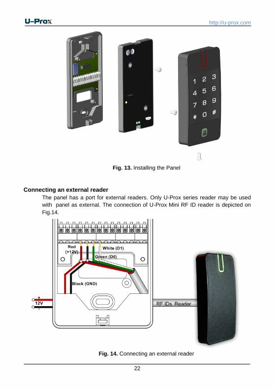
Fig. 13. Installing the Panel
Connecting an external reader
The panel has a port for external readers. Only U-Prox series reader may be used
with panel as external. The connection of U-Prox Mini RF ID reader is depicted on
Fig.14.
Fig. 14. Connecting an external reader

http://u-prox.com
23
Color matching circuits:
White - data 1
Green - data 0
Black – GND
Red - +12
Current consumption of each external reader connected to terminals "12 V" should
not exceed 100 mA. When connecting to panel a reader of long range with current
consumption more than 100 mA, supply the voltage to it from the separate source.
Connecting Loop Control
Panel has two inputs for connecting the loops supervised with end of line resistors.
Each input functionality programmable. Inputs' functions are:
Door Contact
RTE
Door Contact + RTE
Free pass (A, B, A+ B)
Blocking (A, B, A +B)
Sensors monitoring
220V control and battery
The following describes how to connect various types of inputs. After factory reset all
loops have no purpose and are not supervised. All loops work both for closing and
opening.
The use of load resistors is mandatory.
Normal state of the loop - from 1.4 kOm to 3kOm, Line shortage - less than 1.4 kOm,
the broken line - more than 3 kOm.
It is recommended to use supplied resistors.
Request to Exit button (RTE)
RTE is used for exit through single-sided door. In this case, access point opens
when you press and release RTE. Use this input type for remote door opening
button connection also. For example, to open the door manually, by the secretary or
security guard.
Panel U-Prox IP300 has built-in RTE button, which can be activated or deactivated
during programming. The number of the loop of this button - № 3.
By default all inputs and build-in RTE button are off
The example of normally open contact RTE button connection to Z1 terminal is on
the Fig. 15.

http://u-prox.com
24
Fig.15. Connection of RTE button
Z1 input function assigned as follows:
Z1 - RTE of access point A
The use of button of the electric lock to open access point or "allow access"
button on the turnstile evokes the "DOOR FORCED OPEN" event
For proper operation, it is necessary to assign the connected loops as RTE when
programming.
Door Contact
Control panel supervises the door state or position of the turnstile rotor wit the door
contact. Panel cannot detect unauthorized access or door is open too long (multiple
entrance with one ID for instance) without the Door Contact.
The example of normally closed door contact connection to Z1 terminal is on the Fig.
16.
Fig. 16. Connecting door contact
http://u-prox.com
25
Z1 input function assigned as follows:
Z1 - door contact of access point A
Access point, controlled by ACS, must have the door closer.
Program input as 'Door Contact' for proper operation of the door contact.
The control panel can operate without the door contact. In this case, after the
passing RF ID for identify and granting access, an event "Access granted" is
generated, the control panel send unlocking impulse, and returns to normal mode
after door time expire.
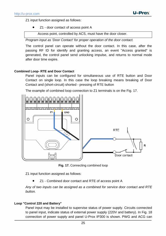
Combined Loop- RTE and Door Contact
Panel inputs can be configured for simultaneous use of RTE button and Door
Contact on single loop. In this case the loop breaking means breaking of Door
Contact and (short-circuit) shorted - pressing of RTE button
The example of combined loop connection to Z1 terminals is on the Fig. 17.
Fig. 17. Connecting combined loop
Z1 input function assigned as follows:
Z1 - Combined door contact and RTE of access point A
Any of two inputs can be assigned as a combined for service door contact and RTE
button.
Loop "Control 220 and Battery"
Panel input may be installed to supervise status of power supply. Circuits connected
to panel input, indicate status of external power supply (220V and battery). In Fig. 18
connection of power supply and panel U-Prox IP300 is shown. PWG and ACG can

http://u-prox.com
26
be open collector outputs or relay outputs (dry contacts) sink to the ground at normal
mains power and battery state respectively.
Fig. 18. Connecting of Control Loop 220 and the battery to power supply
Z2 input function assigned as follows:
Z2 - Control 220 and battery
Actuators
Panel has one relay to supervise actuators. Panel controls electric lock or latch,
barrier operation, turnstile, or turns on and off any optional hardware with this output.
Relay 1 has normally closed and normally open contacts. The relay contacts rating is
1A @ 24 V.
Voltage ripple at actuator operation must not cause the panel malfunction. In case of
such malfunction power up actuators from alternate power supply.
Electric locks
Normally closed and normally open relay contacts, are programmable for a wide
range (0 ... 255 sec) of lock operation time. Thus panel may control a wide range of
electric locks and latches of almost any type.
The example of actuator connection is on the Fig. 19. The first is powering the lock
and second by depowering.
When the lock time is equal to 0 pulse duration of 200 ms will sent to relay.

http://u-prox.com
27
Fig. 19. Connecting locks
When using relay to turn on / off current via inductive load, for example, to run
electromagnetic lock, there are electric pulses of high amplitude. To prevent damage
of relay contacts shunt inductive load by diode, set in opposite direction to voltage of
coil supply
Remember, that low-cost solenoid latch do not allow long power supply. For these
latches program the lock time as short as possible to prevent coil overheating.
Assign relay outputs as outputs of locks at panel programming for proper operation.
Do not use diodes for connecting actuators to AC power supply.

http://u-prox.com
28
Connection
Wired or wireless computer network used for U-Prox IP300 communication to the
ACS server. Device setup is possible with using autoconfiguration or manually with a
PC using the software "Configurator":
Appropriate configuration provides:
Assigning of static or dynamic (DHCP) IP address to a device;
Working with two (primary and backup) IP or DNS (Domain Name Service)
of ACS server addresses;
Working on the Internet (service of remote branches) with the ability of
reserving paths to the Internet via the second router;
Use two Wi-Fi access points (primary and backup)
Panel works automatically after data upload from the ACS server. It processes
access rights for IDs passed grants or denies access and sent event reports to the
server.
Panel communicator operates in notification mode. If there is event (passage, input
violation) data transmission to ACS server is initiated.
Panel provides protection against arbitrary interference due to the encryption of data
with 256-bit key and against panel substitution supervising the unique serial number
of the device at its work in the network. It also provides supervision of the
communication channel by means of periodic test signals from the device.
Wired computer network (Ethernet)
Ethernet interface is used to connect components of the system (PC and panels) in
the network. Ethernet cable length without additional equipment can be up to 100
meters.
Use standard Ethernet cable, which involves four wires: TX , TX-, RX , RX- for
connection. Transfer rate is up to 100Mb / s.
Ehernet
clamps of
panel's
connector
Cable color
Clamps of RJ-45
connector
Direct connection
(to the switch or router)
ORW White-Yellow 1
OR Yellow 2
GNW White-Green 3
GN Green 6

http://u-prox.com
29
Crossover
(directly to the network card in your computer).
Figue 20. Connection cable Ethernet
ORW White-Yellow 3
OR Yellow 6
GNW White-Green 1
GN Green 2
To configure the Ethernet device of panel:
Enable Ethernet communication
Set network parameters of panel (do not set if you use DHCP):
o IP address
o Subnet Mask
o IP address of the gateway (router) Internet 1 (not necessarily in the
local area network)
o IP address of the gateway (router) to the Internet 2 (optional)
o IP address of the DNS Server 1 (if data transfer of the domain name
is used)
o IP address of the DNS Server 2 (optional, if data transfer of the
domain name is used)
Setting communication with server:
o IP or DNS address server 1
o IP or DNS address server 2 (address of U-Prox IC A panel, optional)
o Access Ports (port to read and port to write)
o Period of the link channel checking (test signal)
Wireless computer network (Wi-Fi)
Panel can operate in wireless computer networks of standards IEEE 802.11b/g/n
(2.4GHz frequency, encryption WEP (Open), WPA, WPA2).
Panel supports two Wi-Fi access points (primary and backup) for this communication
channel redundancy.
To configure the Wi-Fi device panel:
Enable Wi-Fi communication
Set up Wi-Fi (for each of used access points):
o Network name - SSID
o Access key (password)
o Encryption mode

http://u-prox.com
30
Set the panel network parameters (do not set if you use DHCP):
o IP address
o Subnet Mask
o IP address of the gateway (router) Internet 1 (not necessarily in the
local area network)
o IP address of the gateway (router) to the Internet 2 (optional)
o IP address of the DNS server 1 (if a data transfer of the domain
name)
o IP address of the DNS Server 2 (optional, if you are using a data on
the domain name)
Set up communication with the server:
o IP or DNS server address 1
o IP or DNS address server 2 (address of U-Prox IC A panel, optional)
o Access Ports (port read and write port)
o Period of the link channel checking (test signal)
http://u-prox.com
31
Panel programing
Software Operation
1. Determination of panel operation mode: standalone or as
part of ACS
Software
"Configurator"
connection
through the USB
port
2. Setting initial parameters: network settings of panel:
a. Type of device - Wi-Fi or Ethernet
b. Wi-Fi key of access to the network and encryption
type (repeat when multiple networks)
c. Server settings: IP address or DNS name of the
server, access ports (port to read, port to write)
Don't proceed paragraph d. if DHCP used in the network.
d. Device Settings: IP address of the device in computer network, subnet mask, IP DNS server, gateway to the Internet
ACS
software
3. Panel enrollment and activation in the access control
system software (refer to the software manual)
4. Set up device with ACS software
a. Door settings: Single-sided or Double-sided door, operation of Antipassback, Time of PIN entering (or off)
b. Access points settings: no. of readers, Door Times, "Alarm Prohibited. Door forced open", "Alarm Prohibited. Door opened too long" attributes
c. Readers settings: reader type of 26 or 42 bit
d. Panel inputs settings: type of reaction and access point (e.g., door sensor, access point of A and B, or a free pass, access point B).
e. Panel outputs settings: type of use (lock, siren, etc.), operating mode, the pulse duration (if available in this mode), access point that operates this output.
5. ACS software creates the list of RF IDS with their attributes,
schedules and access rights based on personnel access
politics programmed in the system (Refer to the ACS software
manual).
6. After forming and loading the configuration from ACS
software the panel is ready for use.
http://u-prox.com
32
Maintenance
Factory reset (before installation)
To return panel to the factory settings, perform the following steps:
1. De-power the panel
2. Remove top cover of panel
3. Unplug the control panel board from the back cover
4. Short D1 (white) and D0 (green) wires
5. Plug the control panel board from the back cover
6. Power up
7. Wait for six signals, signaling the successful panel reset
8. De-power the panel
9. Unplug the control panel board from the back cover
10. Remove short from D1 (white) and D0 (green) wires
Factory reset (after installation)
To return panel to the factory settings, perform the following steps:
1. Do not turn off the power. Remove top cover of panel
2. Connect the notebook running 'Configurator' program with USB cable to the
panel
3. Connect to panel using software “Configurator"
4. Set the parameter "test period" equal to 0 (zero)
5. Upload (write) the new configuration to the panel
The controller will restart with factory settings
Switching to programming mode
To put panel in programming mode do the following:
1. Do not turn off the power. Remove top cover of panel
2. Connect to USB cable and set up the device using software “Configurator"
Replacing the device firmware
1. De-power the panel
2. Remove the top cover of panel
3. Connect the notebook with USB cable to the panel
4. Using special software, do the replacement of panel firmware
5. After downloading the firmware to the panel WAIT for SIX SHORT SIGNALS. It
is the signal of correct firmware loading.
Factory settings
Communicatior
Ethernet mode enabled, DHCP enabled (no device IP set), no ACS server set
Inputs
Z1, Z2, Z3(RTE) – disabled
Outputs
Relay 1 is disabled
Readers
Internal – RS mode, full RF ID (42Bit), External - RS mode, full RF ID (42Bit)