Embed Size (px)
Citation preview

Accepted Article Preview: Published ahead of advance online publication
Get it white: color-tunable AC/DC OLEDs
Markus Fröbel, Tobias Schwab, Mona Kliem, Simone Hofmann, Karl Leo and Malte C. Gather
Cite this article as: Markus Fröbel, Tobias Schwab, Mona Kliem, Simone Hofmann, Karl Leo and Malte C. Gather. Get it white: color-tunable AC/DC OLEDs. Light: Science & Applications accepted article preview 4 December 2014; e247; doi: 10.1038/lsa.2015.20. This is a PDF file of an unedited peer-reviewed manuscript that has been accepted for publication. NPG are providing this early version of the manuscript as a service to our customers. The manuscript will undergo copyediting, typesetting and a proof review before it is published in its final form. Please note that during the production process errors may be discovered which could affect the content, and all legal disclaimers apply.
Received 10 September 2014; revised 2 December 2014; accepted 2 December 2014; Accepted article preview online 4 December 2014
© 2014 Changchun Institute of Optics, Fine Mechanics and Physics (CIOMP), Chinese Academy of Sciences (CAS). All rights reserved.
ACCEPTED ARTICLE PREVIEW

Get it White: Color-tunable AC/DC OLEDs
Markus Fröbel1,*
, Tobias Schwab1, Mona Kliem
1, Simone Hofmann
1, Karl Leo
1, and Malte C. Gather
1,2
1. Institut für Angewandte Photophysik, Technische Universität Dresden, George-Bähr-Straße 1, D-
01069 Dresden, Germany
2. School of Physics and Astronomy, University of St Andrews, North Haugh, St Andrews KY16 9SS,
UK
* Correspondence: Markus Fröbel, TU Dresden, Institut für Angewandte Photophysik, George-Bähr-
Str. 1, 01069 Dresden, Germany
E-mail: [email protected]
Tel. +49-(0)351-463-34902
Fax +49-(0)351-463-37065
Tobias Schwab: [email protected]
Mona Kliem: [email protected]
Simone Hofmann: [email protected]
Karl Leo: [email protected]
Malte C. Gather: [email protected], [email protected]
© 2014 Changchun Institute of Optics, Fine Mechanics and Physics (CIOMP), Chinese Academy of Sciences (CAS). All rights reserved.
ACCEPTED ARTICLE PREVIEW

ABSTRACT
Organic light-emitting diodes (OLEDs) have gained considerable attention because of their use of
inherently flexible materials and their compatibility with facile roll-to-roll and printing processes. In
addition to high efficiency, flexibility, and transparency, reliable color tunability of solid state light
sources is a desirable feature in the lighting and display industry. Here, we demonstrate a device
concept for highly efficient organic light-emitting devices whose emission color can be easily adjusted
from deep-blue through cold-white and warm-white to saturated yellow. Our approach exploits the
different polarities of the positive and negative half-cycles of an alternating current (AC) driving signal
to independently address a fluorescent blue emission unit and a phosphorescent yellow emission unit
which are vertically stacked on top of each other. The electrode design is optimized for simple
fabrication and driving and allows for two-terminal operation by a single source. The presented concept
for color-tunable OLEDs is compatible with application requirements and versatile in terms of emitter
combinations.
KEYWORDS
alternating current; white organic light-emitting devices; color mixing; color tuning; vertical stacking
© 2014 Changchun Institute of Optics, Fine Mechanics and Physics (CIOMP), Chinese Academy of Sciences (CAS). All rights reserved.
ACCEPTED ARTICLE PREVIEW

INTRODUCTION
In recent years, organic light-emitting diodes (OLEDs) have evolved into a mature technology and
OLEDs are now used in various display applications. OLEDs provide an internal charge-to-photon
conversion efficiency of nearly 100% and deliver homogeneous emission over large areas, making
them promising candidates for new and innovative lighting applications.1 White OLEDs, in particular,
offer great potential for energy-efficient general illumination: luminous efficacies of more than
90 lm W-1
, comparable to the best fluorescent tubes, have already been reported.2,3
Furthermore, OLED
based light sources can be made mechanically flexible and transparent, offering new opportunities for
architecture, visual art, and decoration.4 The reliable real-time tunability of the OLED emission color
would impart further momentum to OLED technology on its way to becoming a widespread source of
general illumination. Thus far, two different color-tuning concepts have prevailed in the literature. One
exploits voltage-dependent changes in emission color and was demonstrated as early as 1994 for
OLEDs fabricated from polymer blends.5 Voltage-dependent color shifts are the result of a variety of
mechanisms, e.g., voltage-dependent charge trapping, a spatial shift of the recombination zone, a
modified exciton distribution, or exciton quenching at high current densities.5-7
However, this approach
has several drawbacks: Not only are the mechanisms that lead to voltage-dependent color-shifts
difficult to control, but adjusting the driving voltage also unavoidably results in a dramatic and
undesired change in device brightness. The second concept overcomes the disadvantages of the
voltage-controlled approach by using a stacked tandem OLED structure with two (or more)
independently addressable units emitting light of different colors.8,9
In comparison with the first
method, this approach provides much greater control over the emission spectrum. However, to
individually address each unit, an additional electrode must be added into the device stack as a
connection between two adjacent units. This intermediate electrode must be transparent and therefore
must be made either of a thin metal layer (≈ 15 nm) or from indium tin oxide (ITO).10
However, the
© 2014 Changchun Institute of Optics, Fine Mechanics and Physics (CIOMP), Chinese Academy of Sciences (CAS). All rights reserved.
ACCEPTED ARTICLE PREVIEW

deposition of ITO can be problematic due to sputter-induced damage to the organic material
underneath,11
whereas metal films absorb a significant amount of light and introduce additional micro-
cavity effects.12-14
Hence, the device development of highly efficient color-tunable OLEDs remains
experimentally challenging: the color-tunable OLEDs that have been reported thus far demonstrate
relatively modest efficiencies (< 10% external quantum efficiency (EQE), < 10 lm W-1
), despite the use
of phosphorescent emitter systems.15,16
Although these reports on vertical stacking of two
independently controllable emission units have demonstrated only moderate performance, we believe
that an efficient realization of such a system is a necessary and important step toward RGB full-color
devices in which three independent emission units are stacked on top of each other. Such a vertically
stacked RGB configuration is highly attractive for display applications as it allows for greatly increased
pixel densities and a close-to-optimal utilization of the available display panel area for all colors.
In this work, we demonstrate highly efficient color-tunable white OLEDs based on a combination of a
fluorescent blue emitting unit and a phosphorescent yellow emitting unit for the generation of white
light. In contrast to the majority of publications on this topic, our devices are driven by an alternating
current (AC) signal, which allows us to reduce the required number of independently addressable
electrodes from three to only two.8,16-18
By using an ultra-thin and highly transparent layer of highly
conductive metal as the intermediate electrode,19-21
our devices achieve efficiencies comparable to
those of state-of-the-art non-color-tunable white OLEDs with the additional advantage of providing
continuous color tuning at constant brightness from deep blue through cold-white and warm-white to
saturated yellow. Our device efficiencies of up to 36.8 lm W-1
at warm-white color coordinates are – to
the best of our knowledge – the highest values achieved thus far for any freely color-tunable white
OLED. Furthermore, we compare the performance of three different emitters within the blue emitting
unit and provide general design rules to achieve high luminous efficacies (LE) in such devices. We
refer to our devices as AC-driven direct-current (DC) OLEDs, or AC/DC OLEDs, to clearly distinguish
them from capacitively coupled OLEDs, which operate without direct charge injection from the
© 2014 Changchun Institute of Optics, Fine Mechanics and Physics (CIOMP), Chinese Academy of Sciences (CAS). All rights reserved.
ACCEPTED ARTICLE PREVIEW

electrodes and which are frequently referred to as “AC-OLEDs.”22-24
MATERIALS AND METHODS
Our device architecture comprises a yellow phosphorescent pin-OLED stacked on top of a blue
fluorescent pin-OLED, as schematically illustrated in Figure 1a.25
Internally, our devices contain three
electrodes (labeled E1, E2, and E3 in Figure 1a); however, E1 and E3 are electrically connected inside
the device and thus are at the same potential upon application of a voltage and can be addressed via a
single external contact. E2 is the independent counter-electrode. The polarity between E1/E3 and E2
controls whether the blue- or the yellow-emitting sub-unit of the device is active: When E1/E3 is
placed at a positive potential with respect to E2, we observe blue emission because the blue sub-unit is
biased in forward direction, whereas the yellow sub-unit is biased in reverse direction and thus exhibits
a negligible current density and no yellow emission. Upon a change in polarity, i.e., the application of a
negative voltage to E1/E3, the device emits yellow light, as it is now the yellow-emitting sub-unit that
is biased in forward direction. This polarity-dependent emission is depicted in Figure 1b. To study the
influence of the blue-emitting sub-unit on the performance and color tunability of our AC/DC OLEDs,
we investigated three different blue sub-units based on the blue fluorescent emitters 4P-NPD (sample
S1), PPIP (sample S2), and MADN:TBPe (sample S3); see Figure 1c.
All layers were deposited in a UHV chamber at a base pressure of approximately 10-8
mbar onto glass
substrates coated with structured tin-doped indium oxide (ITO), which served as a transparent bottom
electrode. The thickness and deposition rates of the organic materials were measured via quartz crystal
monitoring (QCM). The evaporation rates varied from 0.3 Å s-1
for the emission layer to 1 Å s-1
for the
p- and n-type layers. Doping was realized by co-evaporation of the matrix material and the dopant.
As the p-type layers, we used 2,2',7,7'-tetrakis-(N,N-di-methylphenylamino)-9,9'-spirobifluorene
(Spiro-TTB) doped with 4 wt% 2,2'-(perfluoronaphthalene-2,6-diylidene)dimalononitrile (F6-
© 2014 Changchun Institute of Optics, Fine Mechanics and Physics (CIOMP), Chinese Academy of Sciences (CAS). All rights reserved.
ACCEPTED ARTICLE PREVIEW

TCNNQ). The n-type layers consist of 4,7-diphenyl-1,10-phenanthroline (BPhen) doped with cesium
(Cs). For the blue emission layer (EML), either N,N'-di-1-naphthalenyl-N,N'-diphenyl-[1,1':4',1'':4'',1'''-
quaterphenyl]-4,4'''-diamine (4P-NPD), 4,4'-bis(1-phenyl-1H-phenanthro[9,10-d]phenanthroimidazol-
2-yl)biphenyl (PPIP), or 2-methyl-9,10-bis(naphthalen-2-yl)anthracene (MADN) doped with 1.5 wt%
2,5,8,11-tetra-tert-butylperylene (TPBe) was used.26
The yellow EML is a double-emission structure,
fabricated from a combination of the primarily hole-conducting 4,4',4''-tris(N-carbazolyl)-
triphenylamine (TCTA) matrix and the electron-conducting 2,2',2''-(1,3,5-phenylen)tris(1-phenyl-1H-
benzimidazol) (TPBi) matrix, both doped with 8 wt% of the phosphorescent yellow emitter bis(2-(9,9-
dihexylfluorenyl)-1-pyridine)(acetylacetonate)iridium(III) (Ir(dhfpy)2(acac)). Electron- and hole-
blocking layers (EBL/HBL) confine the charge carriers and excitons to the EML. In the case of the
yellow-emitting unit, aluminum(III) bis(2-methyl-8-quninolinato)-4-phenylphenolate (BAlq2) and
2,2',7,7'-tetrakis-(N,N-diphenylamino)-9,9'-spirobifluorene (Spiro-TAD) were used as the HBL and
EBL, respectively. The HBL/EBL combinations were different for the different blue-emitting units. In
the case of 4P-NPD and PPIP, we used BPhen/Spiro-TAD and BPhen/N,N'-di(naphthalen-1-yl)-N,N'-
diphenyl-benzidine (alpha-NPD), respectively. For MADN:TBPe, BAlq2 was used as the HBL and
alpha-NPD was used as the EBL. The highly transparent central multilayer electrode is a combination
of 2 nm of gold (Au) and 9 nm of silver (Ag). An aluminum (Al) layer of 100 nm thickness was used as
a highly reflective top electrode. E1 and E3 were processed using the same shadow mask. As the
organic layers do not completely cover E1, the two electrodes have a direct electrical connection. In
this way, our device design allows for easy fabrication and the internal connection between E1 and E3
requires no additional space on the substrate. The active area of the device is 6.49 mm2. Prior to device
investigation, the samples were encapsulated in a nitrogen glovebox.
The current-voltage-luminance (j-V-L) characteristics of our devices were measured using a source
measure unit (SMU 2400, Keithley) in combination with a calibrated Si photo-diode. A calibrated
spectrometer (CAS 140, Instrument Systems) recorded the spectral radiance in forward direction.
© 2014 Changchun Institute of Optics, Fine Mechanics and Physics (CIOMP), Chinese Academy of Sciences (CAS). All rights reserved.
ACCEPTED ARTICLE PREVIEW

Angle-dependent measurements were used to determine the EQE and LE of the blue and yellow units,
respectively, and were performed in a spectrogoniometer setup that included a calibrated Ocean Optics
USB4000 miniature spectrometer. The electrical characteristics of the device under AC driving were
measured using a high-precision digital power meter (WT1600, Yokogawa). The WT1600 measures
current, voltage, and the phase angle between the two quantities to provide correct values for the
dissipated power. The luminous flux under AC conditions was obtained in a calibrated integration
sphere (LMS-100, Labsphere, d = 250 mm).
RESULTS AND DISCUSSION
The electrode design of the AC/DC OLEDs allows to independently investigate the electrical and
optical characteristics of the yellow- and blue-emitting units under DC conditions by changing the
polarity of the applied voltage. Figure 2 presents the j-V-L characteristics for each individual emission
unit, as well as the EQE and LE of each unit. For a negative bias, only the yellow unit is active and the
choice of the blue emitter should not influence the performance. Both the j-V characteristics and the V-
L curves of the yellow unit are indeed identical for all three samples (Figure 2a). As expected, the
differences in efficiency between the individual samples are also within the range of the sample-to-
sample variation (Figure 2c). At a brightness of 1000 cd m-2
, we obtain EQEs of 15-16% and LEs of
50-55 lm W-1
for the yellow units in the various samples. For the three different blue emitters, we
observe very similar j-V behavior and only small differences in the V-L characteristics (Figure 2b).
With regard to efficiency, the AC/DC OLED with 4P-NPD – a deep-blue emitter – exhibits the lowest
LE of approximately 1.2 lm W-1
at 1000 cd m-2
, whereas the sky-blue emitter PPIP and the host:guest
system MADN:TBPe yield LEs of 2.3 lm W-1
and 4.4 lm W-1
, respectively, as shown in Figure 2d. The
EQE values of the three different blue units range from 2.5% in the case of PPIP and over 3.1% in the
case of 4P-NPD to approximately 3.4% in the case of MADN:TBPe. The emission spectra of the blue-
© 2014 Changchun Institute of Optics, Fine Mechanics and Physics (CIOMP), Chinese Academy of Sciences (CAS). All rights reserved.
ACCEPTED ARTICLE PREVIEW
and the yellow-emitting units of samples S1, S2, and S3 are provided in Figure S1 in the
Supplementary Information.
Upon application of an AC signal, the device alternately emits pulses of blue and yellow light. When a
sufficiently high frequency is used, the human eye cannot resolve the separate emission from each unit
but instead perceives a color equivalent to the integrated emission over several operation cycles (cf.
demonstration Movie S1 in the Supplementary Information and Figure 1b). By modifying the pulse
width and/or pulse height ratios between the positive and negative half-cycles of the AC signal, the
relative contributions of blue and yellow emission can be adjusted, thereby allowing for tuning of the
emission color perceived by the human eye (cf. demonstration Movie S2 in the Supplementary
Information).
To study this color tuning in greater detail, we used a square-wave signal with equal pulse lengths in
both the positive and negative half-cycles and tuned the emission color by varying the ratio between the
voltages applied during the forward and backward pulses, as illustrated in the top row of Figure 3. The
emission spectra for the three samples, S1, S2, and S3, are presented in the corresponding rows in
Figure 3. For the spectra shown in columns 1 and 5, the voltage applied during either the negative or
the positive half-cycle is zero, and pure emission from either the blue or the yellow unit can be
observed. Column 3 represents the symmetric situation in which the absolute voltage applied during the
forward and backward pulses is equal, leading to mixed emission from both units (cf. Figure 1b).
Intermediate non-symmetric waveforms lead to a reduced contribution from one of the emission units
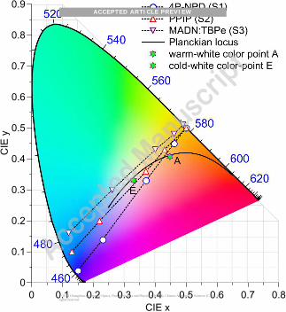
(columns 2 and 4). Figure 4 presents the corresponding CIE coordinates for all emission spectra. The
CIE coordinates associated with the different pulse forms are located along straight lines starting in the
blue region and ending in the yellow region of the color space. The emission spectra of the pure yellow
units are identical for S1, S2, and S3. As a result, all three samples are characterized by the same
yellow color point in the CIE diagram while having different origins in the blue CIE region because of
the different blue emitter systems used. As indicated by dotted lines in the CIE diagram in Figure 4, all
© 2014 Changchun Institute of Optics, Fine Mechanics and Physics (CIOMP), Chinese Academy of Sciences (CAS). All rights reserved.
ACCEPTED ARTICLE PREVIEW

color points on the connecting lines between the beginning and end points can be reached by changing
the ratio of the voltage pulse intensities and hence the fractions of blue and yellow emission
contributing to the resulting spectrum. The color-tuning curves of S1 (4P-NPD) and S2 (PPIP) intersect
the Planckian locus (i.e., the line that describes radiation from black-body radiators at various
temperatures); for S1, this intersection is very close to the warm-white color reference point A.
As the next step, we measured the LEs of S1, S2, and S3 at a brightness of 1000 cd m-2
when the
devices were tuned to warm-white color coordinates. For this experiment, color tuning was performed
by adjusting the “on time” of each unit, i.e., by varying the relative pulse widths of the positive and
negative half-cycles at equal and constant pulse heights or driving voltages. Compared with the
previously demonstrated pulse height modulation, this approach allows for finer tuning of the emission
color, as small changes in the on time ratio between the two units also lead to small shifts in emission
color. By contrast, small variations in the driving voltage result in large variations in luminance
(because of the super-linear diode behavior of the individual units) which lead to strong color shifts.
For all three samples, Table 1 summarizes the LE, the CIE color coordinates, the color rendering index
(CRI), and the on time ratio between the blue and yellow units that was required to reach the color
point A. Samples S2 (PPIP) and S3 (MADN:TBPe) achieved LEs of 31.5 lm W-1
and 27.9 lm W-1
,
respectively.
Table 1 CIE color coordinates, color rendering index (CRI), on time ratio of the blue and yellow units,
and luminous efficacy for S1, S2, and S3.
Sample Blue Emitter CIE CRI On time [%] a
blue unit / yellow unit
Luminous efficacy b
[lm W-1
]
S1 4P-NPD (0.44, 0.45) 38 15 / 85 36.8
S2 PPIP (0.44, 0.47) 36 20 / 80 31.5
S3 MADN:TBPe (0.41, 0.44) 35 30 / 70 27.9
a 50 Hz AC signal, 2.93 Vrms, equal pulse heights for positive and negative half-cycles
b at a brightness of 1000 cd m
-2
© 2014 Changchun Institute of Optics, Fine Mechanics and Physics (CIOMP), Chinese Academy of Sciences (CAS). All rights reserved.
ACCEPTED ARTICLE PREVIEW

Interestingly, the white AC/DC OLED with 4P-NPD achieved the highest LE, although the LE of 4P-
NPD is considerably lower than those of the other two blue emitters (cf. Figure 2d). This observation is
explained by the considerable difference in LE between the blue and yellow emitter systems (cf.
Figures 2c and 2d), as the phosphorescent yellow unit has a 40-fold higher LE than does the fluorescent
blue unit. It is therefore important to maximize the on-time of the yellow emitter and keep the
contribution of the blue emitter to a minimum. Considering the on time ratios of the three emitter
systems under investigation (cf. Table 1), we find that this is best achieved using the deep-blue emitter
4P-NPD, for which the on time of the blue unit for warm-white emission is merely 15%. The more sky-
blue emitters PPIP and MADN:TBPe require increased on times of 20% and 30%, respectively,
resulting in reduced LEs compared with the 4P-NPD sample. The obtained efficiency value of 36.8 lm
W-1
is even higher than the value of 32.6 lm W-1
that has recently been achieved for non-color-tunable
white OLEDs using the same emitter materials in a triplet-harvesting configuration27
and, to our
knowledge, represents the best efficiency achieved thus far for any freely color-tunable white OLED.
As previously mentioned, the high efficiency of AC/DC OLEDs results predominantly from the high
efficiency of the yellow unit, which can operate close to its maximum internal quantum efficiency
because of the direct electrical excitation. By contrast, the internal quantum efficiency of the yellow
emitter in the triplet-harvesting white OLED is limited to approximately 50% because of the moderate
exciton-harvesting efficiency.27
The low CRI values for all three samples (cf. Table 1) result from the combination of only two emitters
(blue and yellow) to obtain white light, which means that important contributions in the green and
deep-red spectral regions are missing. However, as the device design of AC/DC OLEDs is highly
flexible in terms of emitter combinations, this problem of low CRI can be addressed quite easily, e.g.,
by modifying the blue emission unit into a blue+red triplet-harvesting emission unit and replacing the
yellow phosphor with a green phosphorescent emitter. The presence of red, green, and blue emitters
would guarantee a high CRI, and the combination of a highly efficient triplet-harvesting unit (blue+red
© 2014 Changchun Institute of Optics, Fine Mechanics and Physics (CIOMP), Chinese Academy of Sciences (CAS). All rights reserved.
ACCEPTED ARTICLE PREVIEW

can be more efficient than blue+yellow because of the more favorable relative triplet energy levels) and
a phosphorescent green emitter is expected to result in high overall efficiency.
The operational stability of AC/DC white OLEDs is comparable to that of conventional DC driven
white OLEDs, and in preliminary tests, we did not observe any adverse effects of driving these devices
with an AC signal instead of the commonly used DC bias.
CONCLUSIONS
In summary, we demonstrated highly efficient color-tunable AC/DC OLEDs based on a combination of
a blue-emitting unit and a yellow-emitting unit. The fabrication and electrical driving of these devices
was simplified by reducing the number of independent electrodes to two and using an AC voltage for
color tuning. Color tuning can be accomplished either by modifying the pulse height or by adjusting the
pulse width ratio between the positive and negative half-cycles of the AC signal. The influence of the
central electrode on the optical characteristics of the OLEDs was reduced by using a highly transparent
thin-film metal electrode. In combination with the deep-blue fluorescent emitter 4P-NPD, this leads to
an impressive luminous efficacy of 36.8 lm W-1
at warm-white color coordinates of (0.44, 0.45) and at
brightness levels compatible with application requirements (1000 cd m-2
). All efficacy values reported
here were obtained without any outcoupling enhancement. By integrating well-established light-
extraction techniques, a two- to three-fold improvement in luminous efficacy can be achieved.28
To demonstrate the versatility of our approach and to investigate the influence of different blue emitters
on the device performance, measurements were performed using the sky-blue emitter systems PPIP and
MADN:TBPe. These measurements indicated that the use of a deep-blue emitter such as 4P-NPD is
beneficial for obtaining a high luminous efficacy, as it allows the on time of the blue unit to be reduced.
In future work, this concept could be extended to three pin-OLEDs stacked on top of each other to
provide red, green, and blue emission. This configuration is particularly interesting for display
© 2014 Changchun Institute of Optics, Fine Mechanics and Physics (CIOMP), Chinese Academy of Sciences (CAS). All rights reserved.
ACCEPTED ARTICLE PREVIEW

applications, in which a vertical stacking of the red, green, and blue sub-pixels would allow for higher
pixel densities and an optimal fill factor in comparison with conventional side-by-side fabrication.
ACKNOWLEDGMENTS
This work was funded by the European Social Fund and the Free State of Saxony through the
OrthoPhoto project.
SUPPLEMENTARY INFORMATION
Supplementary information accompanies the manuscript on the Light: Science & Applications website
(http://www.nature.com/lsa/).
REFERENCES
1 Sasabe H, Kido J. Development of high performance OLEDs for general lighting. J Mater Chem C
2013; 1: 1699-1707.
2 Reineke S, Lindner F, Schwartz G, Seidler N, Walzer K, Lüssem B et al. White organic light-emitting
diodes with fluorescent tube efficiency. Nature 2009; 459: 234-238.
3 Rosenow TC, Furno M, Reineke S, Olthof S, Lüssem B, Leo K. Highly efficient white organic light-
emitting diodes based on fluorescent blue emitters. J Appl Phys 2010; 108: 113113.
4 OLED-Info.com. Beautiful OLED lighting designs at LG's design contest. Available from:
http://www.oled-info.com/beautiful-oled-lighting-designs-lgs-design-contest, accessed: August, 2014.
© 2014 Changchun Institute of Optics, Fine Mechanics and Physics (CIOMP), Chinese Academy of Sciences (CAS). All rights reserved.
ACCEPTED ARTICLE PREVIEW
5 Berggren M, Inganäs O, Gustafsson G, Rasmusson J, Andersson MR, Hjertberg T et al. Light-
emitting diodes with variable colours from polymer blends. Nature 1994; 372: 444-446.
6 Yang Y, Pei Q. Voltage controlled two color light‐ emitting electrochemical cells. Appl Phys Lett
1996; 68: 2708.
7 Gather MC, Alle R, Becker H, Meerholz K. On the Origin of the Color Shift in White-Emitting
OLEDs. Adv Mater 2007; 19: 4460-4465.
8 Burrows PE, Forrest SR, Sibley SP, Thompson ME. Color‐ tunable organic light‐ emitting devices.
Appl Phys Lett 1996; 69: 2959.
9 Parthasarathy G, Gu G, Forrest SR. A Full-Color Transparent Metal-Free Stacked Organic Light
Emitting Device with Simplified Pixel Biasing. Adv Mater 1999; 11: 907-910.
10 Shen Z, Burrows PE, Bulovic V, Forrest SR, Thompson ME. Three-Color, Tunable, Organic Light-
Emitting Devices. Science 1997; 276: 2009-2011.
11 Kim HK, Kim DG, Lee KS, Huh MS, Jeong SH, Kim KI et al. Plasma damage-free sputtering of
indium tin oxide cathode layers for top-emitting organic light-emitting diodes. Appl Phys Lett 2005;
86: 183503.
12 Deppe DG, Lei C, Lin CC, Huffaker DL. Spontaneous emission from planar microstructures. J Mod
Opt 1994; 41: 325-344.
13 Becker H, Burns SE, Tessler N, Friend RH. Role of optical properties of metallic mirrors in
microcavity structures. J Appl Phys 1997; 81: 2825.
14 Zhang XW, Li J, Zhang L, Jiang XY, Haq K, Zhu WQ et al. Top-emitting organic light-emitting
device with high efficiency and low voltage using a silver–silver microcavity. Thin Solid Films 2010;
518: 1756-1759.
15 Jiang Y, Lian J, Chen S, Kwok HS. Fabrication of color tunable light-emitting diodes by an
alignment free mask patterning method. Org Electr 2013; 14: 2001-2006.
16 Joo CW, Moon J, Han JH, Huh JW, Lee J, Cho NS et al. Color temperature tunable white light-
© 2014 Changchun Institute of Optics, Fine Mechanics and Physics (CIOMP), Chinese Academy of Sciences (CAS). All rights reserved.
ACCEPTED ARTICLE PREVIEW

emitting diodes. Org Electr 2013; 15: 189-195.
17 Gu G, Khalfin V, Forrest SR. High-efficiency, low-drive-voltage, semitransparent stacked organic
light-emitting device. Appl Phys Lett 1998; 73: 2399.
18 Liang CJ, Choy WCH. Tunable full-color emission of two-unit stacked organic light-emitting diodes
with dual-metal intermediate electrode. J Organomet Chem 2009; 694: 2712-2716.
19 Schubert S, Meiss J, Müller-Meskamp L, Leo K. Improvement of Transparent Metal Top Electrodes
for Organic Solar Cells by Introducing a High Surface Energy Seed Layer. Adv Energy Mater 2013; 3:
438-443.
20 Schwab T, Schubert S, Hofmann S, Fröbel M, Fuchs C, Thomschke M et al. Highly Efficient Color
Stable Inverted White Top-Emitting OLEDs with Ultra-Thin Wetting Layer Top Electrodes. Adv Opt
Mater 2013; 1: 707-713.
21 Schwab T, Schubert S, Müller-Meskamp L, Leo K, Gather MC. Eliminating Micro-Cavity Effects in
White Top-Emitting OLEDs by Ultra-Thin Metallic Top Electrodes. Adv Opt Mater 2013; 1: 921-925.
22 Perumal A, Fröbel M, Gorantla S, Gemming T, Lüssem B, Eckert J et al. Novel Approach for
Alternating Current (AC)-Driven Organic Light-Emitting Devices. Adv Funct Mater 2012; 22: 210-
217.
23 Fröbel M, Perumal A, Schwab T, Gather MC, Lüssem B, Leo K. Enhancing the efficiency of
alternating current driven organic light-emitting devices by optimizing the operation frequency. Org
Electr 2013; 14: 809-813.
24 Fröbel M, Perumal A, Schwab T, Fuchs C, Leo K, Gather MC. White light emission from
alternating current organic light-emitting devices using high frequency color-mixing. Phys Status Solidi
A 2013; 210: 2439-2444.
25 Huang J, Pfeiffer M, Werner A, Blochwitz J, Leo K, Liu S. Low-voltage organic electroluminescent
devices using pin structures. Appl Phys Lett 2002; 80: 139.
26 Kuo CJ, Li TY, Lien CC, Liu CH, Wu FI, Huang MJ. Bis(phenanthroimidazolyl)biphenyl
© 2014 Changchun Institute of Optics, Fine Mechanics and Physics (CIOMP), Chinese Academy of Sciences (CAS). All rights reserved.
ACCEPTED ARTICLE PREVIEW

derivatives as saturated blue emitters for electroluminescent devices. J Mater Chem 2009; 19: 1865-
1871.
27 Hofmann S, Furno M, Lüssem B, Leo K, Gather MC. Investigation of triplet harvesting and
outcoupling efficiency in highly efficient two-color hybrid white organic light-emitting diodes. Phys
Status Solidi A 2013; 210: 1467-1475.
28 Saxena K, Jain V, Mehta DS. A review on the light extraction techniques in organic
electroluminescent devices. Opt Mater 2009; 32: 221-233.
FIGURE LEGENDS
Figure 1 (a) Schematic illustration of the architecture of the investigated color-tunable AC/DC OLEDs
with electrodes and wiring connected to an AC power supply (VAC). Electrodes E1 and E3 are
connected to each other and E2 is the independent counter electrode, allowing for two-terminal device
operation using only one power supply. (b) Photographs showing an AC/DC OLED sample upon
application of a DC bias (blue emission), a DC bias with reversed polarity (yellow emission), and an
AC voltage with a frequency of 50 Hz (white emission). (c) Chemical structures of 4P-NPD, PPIP, and
MADN:TBPe which were the three blue emitter systems investigated in this study.
© 2014 Changchun Institute of Optics, Fine Mechanics and Physics (CIOMP), Chinese Academy of Sciences (CAS). All rights reserved.
ACCEPTED ARTICLE PREVIEW

Figure 2 Current density (j) and luminance (L) as functions of voltage (V) for the (a) yellow-emitting
units and (b) blue-emitting units of samples S1, S2, and S3. The corresponding EQE and LE values as
functions of luminance are presented in (c) and (d) for the yellow and blue units, respectively. Data
were acquired during DC operation, neglecting leakage currents through the reverse-biased opposite
unit of the device.
Figure 3 Emission spectra of S1, S2, and S3 when the five different 50 Hz square-wave signals
depicted in the top row are applied. Columns 1 and 5 represent pure emission from the blue or yellow
unit, as either the negative or the positive half-cycle is zero. Column 3 represents mixed emission from
both units when the samples are driven by a symmetrical signal. Intermediate waveforms lead to a
reduced contribution from one of the emission units (columns 2 and 4).
Figure 4 Color coordinates corresponding to the emission spectra presented in Figure 3 for S1, S2, and
S3.
© 2014 Changchun Institute of Optics, Fine Mechanics and Physics (CIOMP), Chinese Academy of Sciences (CAS). All rights reserved.
ACCEPTED ARTICLE PREVIEW

© 2014 Changchun Institute of Optics, Fine Mechanics and Physics (CIOMP), Chinese Academy of Sciences (CAS). All rights reserved.
ACCEPTED ARTICLE PREVIEW

© 2014 Changchun Institute of Optics, Fine Mechanics and Physics (CIOMP), Chinese Academy of Sciences (CAS). All rights reserved.
ACCEPTED ARTICLE PREVIEW

© 2014 Changchun Institute of Optics, Fine Mechanics and Physics (CIOMP), Chinese Academy of Sciences (CAS). All rights reserved.
ACCEPTED ARTICLE PREVIEW
© 2014 Changchun Institute of Optics, Fine Mechanics and Physics (CIOMP), Chinese Academy of Sciences (CAS). All rights reserved.
ACCEPTED ARTICLE PREVIEW


![Coherent mode coupling in highly efficient top-emitting ...modes in bottom-emitting OLEDs, including the use of macroscopic outcoupling structures like microlens arrays [10,11] or](https://img.dokumen.tips/doc/110x75/60f8a6f7db0578157662badb/coherent-mode-coupling-in-highly-eficient-top-emitting-modes-in-bottom-emitting.jpg)