Embed Size (px)
Citation preview

PERFORMANCE TEST REPORT
Rendered to:
R.H. TAMLYN & SONS, LP
PRODUCT: TamlynWrap™
Report No.: C4879.05-117-16 Report Date: 03/31/14 Test Record Retention Date: 09/23/17
Architectural Testing
130 Derry Court York, PA 17406-8405 phone: 717-764-7700 fax: 717-764-4129 www.archtest.com
Architectural Testing

PERFORMANCE TEST REPORT
C4879.05-117-16 March 31, 2014
TABLE OF CONTENTS
1.0 General Information ............................................................................................................. 1
2.0 Referenced Standards........................................................................................................... 3
3.0 Summary of Test Results ..................................................................................................... 4
4.0 Dry Breaking Force.............................................................................................................. 5
5.0 Water Resistance .................................................................................................................. 6
6.0 Water Vapor Transmission .................................................................................................. 8
7.0 Cold Mandrel Bend .............................................................................................................. 9
8.0 Air Permeance .................................................................................................................... 10
9.0 Drainage Efficiency ........................................................................................................... 12
10.0 Combustibility.................................................................................................................... 16
11.0 Closing Statement .............................................................................................................. 17
Revision Log ................................................................................................................................. 18
Appendix A - Installation Detail
Appendix B - Photographs
Appendix C - Manufacturer's Declaration
Appendix D - Air Permeance Actual Pressure and Flow Values
Appendix E - Air Permeance Graph
Architectural Testing
130 Derry Court York, PA 17406-8405 phone: 717-764-7700 fax: 717-764-4129 www.archtest.com
Architectural Testing

PERFORMANCE TEST REPORT
Rendered to:
R.H. TAMLYN & SONS, LP 13623 Pike Road
Stafford, Texas 77477
Report No.: C4879.05-117-16 Test Dates: 01/22/13 Through: 09/06/13 Report Date: 03/31/14 Test Record Retention Date: 09/23/17 1.0 General Information
1.1 Product
TamlynWrap™
1.2 Project Summary
Architectural Testing was contracted by Benjamin Obdyke, Inc. to perform testing on the TamlynWrap™. The purpose of testing was code compliance evaluation according to ICC-ES AC38, Acceptance Criteria for Water-Resistive Barriers (approved December 2011). This report is a reissue of the original Report No. C4879.01-117-16. This report is reissued in the name of R.H. Tamlyn & Sons, LP through written authorization of Benjamin Obdyke, Inc.
Testing reported herein also complies with the requirements of ICC-ES AC38, Acceptance Criteria for Water-Resistive Barriers (approved January 2013), except that the referenced version of ASTM E 84 was updated from 2007 to 2009 and the referenced version of ASTM E 96 was updated from 2000 ɛ1 to 2005.
1.3 Product Description
The TamlynWrap™ is a polymeric-based, water-resistive barrier with wavy, latitudinal plastic filaments with indents throughout the length that provide an integrated moisture management system. The filaments are also referred to herein as a "plastic drainage lines". The product is installed with mechanical fasteners and as further described herein. Reference the installation detail in Appendix A and the photograph in Appendix B.
Architectural Testing

C4879.05-117-16 Page 2 of 18
1.0 General Information (Continued)
1.4 Qualifications
Architectural Testing in York, PA has demonstrated compliance with ANS/ISO/IEC Standard 17025 and is consequently accredited as a Testing Laboratory (TL-144) by International Accreditation Service, Inc. Architectural Testing is accredited to perform all testing reported herein.
1.5 Product Sampling
Per section 3.2 of ICC-ES AC85, as referenced by section 2.4.3 of ICC-ES AC38, test specimens are not required to be independently sampled if, along with the test report, the manufacturer submits a signed and dated declaration certifying that the product tested is representative of the standard manufactured product to be covered in the evaluation report. Refer to Appendix C the manufacturer's declaration. For all testing reported herein, samples were prepared by Architectural Testing from a single roll of material that was supplied by the manufacturer and that was received by Architectural Testing on 01/16/13.
1.6 Witnessing
There were no client representatives present to witness testing reported herein.
1.7 Conditions of Testing
Unless otherwise indicated, all testing reported herein was conducted in a laboratory set to maintain temperature in the range of 68 ±4ºF and humidity in the range of 50 ±5% RH. All test specimen materials were stored in the laboratory environment for no less than 40 hours prior to testing.
Architectural Testing

C4879.05-117-16 Page 3 of 18
2.0 Referenced Standards
The TamlynWrap™ was evaluated in accordance with the following test methods as modified by ICC-ES™ AC38 (approved December 2011). Any deviation from a method is noted in the respective section of this report.
AATCC Test Method No. 127-1985, Water Resistance: Hydrostatic Pressure Test, American Association of Textile Chemists and Colorists
ASTM D 5034-95, Standard Test Method for Breaking Strength and Elongation of Textile Fabrics (Grab Test), ASTM International
ASTM E 84-07, Standard Test Method for Surface Burning Characteristics of Building Materials, ASTM International
Additionally, ASTM E 84-09 is noted on page 1 as being referenced by ICC-ES AC38 (approved January 2013)
ASTM E 96-00ɛ1, Standard Test Methods for Water Vapor Transmission of Materials, ASTM International
Additionally, ASTM E 96-05 is noted on page 1 as being referenced by ICC-ES AC38 (approved January 2013)
ASTM E 2178-03, Standard Test Method for Air Permeance of Building Materials, ASTM International
ASTM E 2273-03, Test Method for Determining the Drainage Efficiency of Exterior Insulation and Finish Systems (EIFS) Clad Wall Assemblies, ASTM International
Architectural Testing

C4879.05-117-16 Page 4 of 18
3.0 Summary of Test Results
Following is a summary of the test results reported herein. Refer to the photographs in Appendix B.
ICC-ES™
AC38 Section
Test Method Test Results
3.3.1 Dry Breaking Force / ASTM D 5034
Cross-Machine Direction 52.3 lbf
Machine Direction 60.2 lbf
3.3.2 / 4.2.1
Water Resistance / AATCC Test Method No. 127
Control No water leakage
Weathered No water leakage
3.3.3 Water Vapor Transmission / ASTM E 96 (Dessicant Method) 14.9 g/24hr·m2
3.3.4 Cold Mandrel Bend
Cross-Machine Direction
House wrap did not crack; filaments did not crack
Machine Direction
House wrap did not crack; filaments cracked
3.5 Air Permeance / ASTM E 2178 < 0.004 L/(s·m2)
3.6 / 4.3 Drainage Efficiency / ASTM E 2273 ≥ 95.7%
5.3 Combustibility / ASTM E 84 FSI = 10
SDI = 115
Architectural Testing

C4879.05-117-16 Page 5 of 18
4.0 Dry Breaking Force
4.1 Referenced Standards ICC-ES™ AC38, Section 3.3.1; ASTM D 5034 (Grab Test)
4.2 Test Procedure The breaking force was determined on 6 in. long by 4 in. wide test specimens utilizing an Instron Model 3369 Universal Test Machine (ICN 005740) operating at a constant rate of extension of 12 in/min. The starting distance between the 1 inch x 1 inch clamps was 3 inches.
4.3 Test Results
Cross-Machine Direction
Specimen No. Breaking Force, lbf
Duration of Test, seconds
1 51.5 11.35 2 50.0 10.50 3 54.3 12.75 4 53.7 11.35 5 52.3 11.15 6 52.7 11.00 7 53.2 11.85 8 51.0 10.15
Average 52.3 11.26
Machine Direction
Specimen No. Breaking Force, lbf
Duration of Test, seconds
1 60.4 10.00 2 58.0 9.85 3 60.0 10.45 4 63.0 10.90 5 59.5 9.60
Average 60.2 10.16
4.4 Conclusion
Section 3.3.1 of AC38 requires that, for tests conducted under section 4.2 of AC38 (in this case, ASTM D 5034), the conditions of acceptance are as noted in Table 1 of AC38: average breaking force of 35 pounds of force in the cross-machine direction and 40 pounds of force in the machine direction. The test specimens meet these requirements.
Architectural Testing

C4879.05-117-16 Page 6 of 18
5.0 Water Resistance
5.1 Referenced Standards
ICC-ES™ AC38, Sections 3.3.2, 4.1, and 4.2.1; AATCC Test Method No. 127
5.2 Weathering Procedure
Per AC38 section 4.1, two 18 inch x 48 inch pieces of house wrap were exposed to light from ultraviolet sun lamps 10 hours per day for 21 days. The house wrap temperature was between 135 ºF and 140 ºF (57 ºC and 60 ºC). The surface of the house wrap was situated 2' from the bottom of the sun lamps. The sun lamp bulbs provided 5.0 W/m2/nm irradiance at 1 meter for wavelengths of 315 to 400 nm. Three 10 inch square specimens were cut from the two ultraviolet light exposed specimens. They were subjected to 25 cycles of the following accelerated weathering: three hours of oven drying at 120 ºF (49 ºC) with all surfaces exposed, three hours water immersion with all surfaces exposed and eighteen hours air drying at laboratory conditions with all surfaces exposed.
Weathering Completed
Specimen No. Observations
UV 1 No visual change in appearance and no visual deterioration 2 No visual change in appearance and no visual deterioration
UV and Accelerated
1 No visual change in appearance and no visual deterioration 2 No visual change in appearance and no visual deterioration 3 No visual change in appearance and no visual deterioration
5.3 Water-Resistance Test Procedure
The water resistance of three control specimens and three UV/accelerated weathered specimens was tested at a hydrostatic head of 55 cm for a period of five hours. Each specimen was secured to a 14.6 cm diameter by 55 cm high section of pipe with silicone sealant. The sections of pipe were filled with room temperature tap water. After five hours the test specimens were observed for water leakage.
Architectural Testing
C4879.05-117-16 Page 7 of 18
5.0 Water Resistance (Continued)
5.4 Water-Resistance Test Results
Specimen No.
Hydrostatic Pressure,
cm
Test Time, hours Observations
Controls 1 55 5 No water leakage 2 55 5 No water leakage 3 55 5 No water leakage
UV/Accelerated Weathered
1 55 5 No water leakage 2 55 5 No water leakage 3 55 5 No water leakage
5.5 Conclusion
Section 3.3.2 of AC38 requires that, for tests conducted under section 4.2 of AC38 (in this case, AATCC Test Method No. 127), there be no leakage on the underside of any specimen. The tested specimens meet this requirement.
Architectural Testing

C4879.05-117-16 Page 8 of 18
6.0 Water Vapor Transmission
6.1 Referenced Standards
ICC-ES™ AC38, Section 3.3.3; ASTM E 96
6.2 Test Procedure
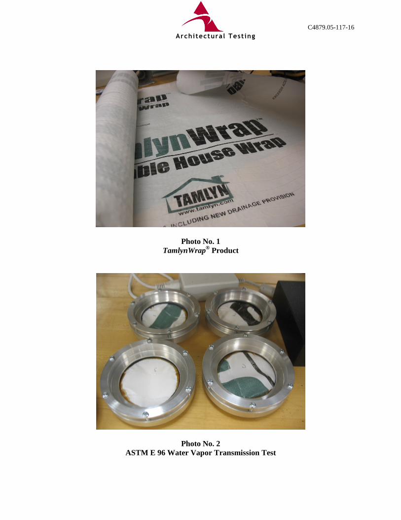
Each test specimen was cut to fit the circular aluminum test dish then secured exterior face up between two gaskets to a calcium chloride-filled test dish for desiccant cup testing. This resulted in the higher water vapor pressure on the outside of the test specimen assembly. The resulting open area of each test specimen for testing was 7.1 in2. The exterior face of the house wrap product remained in direct contact with the laboratory conditions. The weights of the test specimen assemblies were recorded once a day during normal business days utilizing a Mettler Toledo AX504 Balance (ICN 003449). The lab environmental conditions were recorded at the same time. The permeance and water vapor transmission rate were calculated. The permeability was not calculated since the test specimens were less than 0.5 inch thick.
6.3 Test Results
Specimen No.
Average Temp.
(ºC)
Average Relative
Humidity (%)
Permeance Water Vapor Transmission Rate
(perms) ng/(Pa·s·m2) g/(hr·m2) g/(24hr·m2)
1 20.6 49.3 1.818 104 0.4595 11.028
2 20.6 49.3 2.033 116 0.5139 12.334
3 20.6 49.3 3.529 202 0.8910 21.384
Average 2.460 141 0.6215 14.915
6.4 Conclusion
Section 3.3.3 of AC38 states that, for tests conducted per ASTM E 96, the conditions of acceptance are as noted in Table 1 of AC38. Based on the average water vapor transmission rate of the tested specimens, this product meets the criteria of a Grade C water-resistive barrier (i.e. no minimum and no maximum water vapor transmission).
Architectural Testing

C4879.05-117-16 Page 9 of 18
7.0 Cold Mandrel Bend
7.1 Referenced Standard
ICC-ES™ AC38, Section 3.3.4
7.2 Test Procedure
The 3 inch x 8 inch test specimens and 1/16-inch mandrel were conditioned to 32 ºF (0 ºC) and the test specimens with the exterior side in tension were bent over the mandrel at 32 ºF (0 ºC) to check for cracking.
7.3 Test Results
Direction Specimen No. Observations
Cross
1 House wrap did not crack 2 House wrap did not crack 3 House wrap did not crack 4 House wrap did not crack 5 House wrap did not crack
Machine
1 House wrap did not crack; plastic drainage lines cracked 2 House wrap did not crack; plastic drainage lines cracked 3 House wrap did not crack; plastic drainage lines cracked 4 House wrap did not crack; plastic drainage lines cracked 5 House wrap did not crack; plastic drainage lines cracked
7.4 Conclusion
Section 3.3.4 of AC38 requires that the material does not crack when bent over a 1/16-inch diameter mandrel at a temperature of 32 °F. The specimens tested in the cross-machine direction meet this requirement. The water-resistive barrier portion ("house wrap") of the specimens tested in the machine direction meet this requirement, but the drainability portion ("plastic drainage lines") of the specimens tested in the machine direction do not meet this requirement.
Architectural Testing

C4879.05-117-16 Page 10 of 18
8.0 Air Permeance
8.1 Referenced Standards
ICC-ES™ AC38, Section 3.5; ASTM E 2178
8.2 Test Procedure
The test specimen was placed with the exterior up on top of the test chamber (ICN 004933) and then sealed to the test chamber utilizing duct tape and 6 mil thick polyethylene sheeting. The resulting test area was 1 meter x 1 meter (39.3 inches x 39.3 inches). The test specimen was then tested at preset air pressures ranging from 25 Pa to 300 Pa. Upon completion of the cycle, the polyethylene sheet was sliced and peeled away from the test specimen's surface. The test specimen was tested again at preset air pressures ranging from 25 Pa to 300 Pa and the air permeance calculated in accordance with the standard.
8.3 Test Results
TamlynWrap™ Air
Pressure, Pa
Measured Flow Rate, L/(s·m2) Specimen No.
1 2 3 4 5 25 0.00041 0.00126 0.00036 0.00033 0.00040 50 0.00142 0.00254 0.00216 0.00062 0.00077 75 0.00182 0.00365 0.00358 0.00065 0.00102 100 0.00257 0.00467 0.00445 0.00114 0.00197 150 0.00440 0.00657 0.00642 0.00175 0.00274 300 0.00731 0.01156 0.01153 0.00329 0.00468
Architectural Testing

C4879.05-117-16 Page 11 of 18
8.0 Air Permeance (Continued)
8.3 Test Results (Continued)
TamlynWrap™ Air Pressure,
Pa Calculated Flow Rate Calculated Air Permeance,
L/(Pa·m2·s) L/(s·m2) cfm/ft2 25 0.0005 0.00010 0.000022 50 0.0011 0.00022 0.000023 75 0.0018 0.00035 0.000023 100 0.0024 0.00047 0.000024 150 0.0037 0.00073 0.000024 300 0.0077 0.00152 0.000026
Note: The actual pressure and flow values are presented in Appendix D, and the air permeance graph appears in Appendix E.
1/2" Drywall (One Specimen) Air Pressure,
Pa Calculated Flow Rate Calculated Air Permeance,
L/(Pa·m2·s) L/(s·m2) cfm/ft2 25 0.0030 0.00059 0.000121 50 0.0056 0.00110 0.000112 75 0.0081 0.00159 0.000108 100 0.0104 0.00205 0.000104 150 0.0150 0.00295 0.000100 300 0.0278 0.00547 0.000093
Note: The actual pressure and flow values are presented in Appendix D.
8.4 Conclusion
Section 3.5 of AC38 requires that, for tests conducted per ASTM E 2178, the minimum conditions of acceptance shall be an air permeance less than or equal to 0.02 L/(s·m2) at 75 Pa for all test specimens. The tested specimens meet this requirement.
Architectural Testing

C4879.05-117-16 Page 12 of 18
9.0 Drainage Efficiency
9.1 Referenced Standards
ICC-ES™ AC38, Sections 3.6 and 4.3; ASTM E 2273
9.2 Test Procedure
A total of two moisture drainage assemblies were prepared by a representative of Architectural Testing and were evaluated in accordance with the procedures detailed in ASTM E 2273. The base wall consisted of #2 Spruce-Pine-Fir nominal 2x4 lumber to form a 4 feet wide by 8 feet high test specimen. Two studs were spaced 16 inches on center and were attached to the top and bottom plates with 3 inch long drywall screws. A sheet of nominal 1/2 inch thick OSB was fastened to the studs with #6 x 1-5/8 inch long drywall screws, spaced 12 inches on center. A single layer of TamlynWrap™ was applied to the base wall with the patterned filaments oriented horizontally. The house wrap was secured with 1/2 inch wide staples, spaced 12 inches on center. On top of the TamlynWrap™ a 1 inch thick foam insulation board was applied and secured with 2 inch long cap nails, spaced 16 inches on center. Wire mesh was applied over the foam insulation and was secured with 2 inch long nails. A 3/8 inch thick scratch coat was then applied to the wire mesh. The following procedures were applied to both test specimens:
A. Clear acrylic plastic spray box measuring 24-1/2 inches by 9-1/2 inches by 7-1/4 inches was mounted on top of the test frame. The spray box was mounted to ensure that all water was directed into the drainage mesh.
B. The spray box contained two spray nozzles. The nozzles were mounted 1/2 inch from the front edge of the spray box and 5 inches to the right and to the left of center.
C. A drain basin was located below the test specimen which collected the water draining from the wall assembly and directed it into a container with a known weight.
D. The specimen was sprayed for the duration of 75 minutes. The water draining from the wall assembly was collected and weighed at each 15 minute interval during testing.
E. The water spray was terminated after 75 minutes. The specimen was allowed to drain for an additional 60 minutes and the collected water was weighed on our OHAUS® (ICN 63446) scale.
Architectural Testing

C4879.05-117-16 Page 13 of 18
9.0 Drainage Efficiency (Continued)
9.3 Test Results
AC38, Section 3.6 (ASTM E 2273) - Drainage Test
Test Specimen No. 1 Calibration Data: In accordance with the standard, the water spray applicator was calibrated prior to the test being completed. The calibration results are as follows:
Date Weight of water
drained after 15 minutes 1 (lb)
Calculated weight, total water applied
after 75 minutes (lb)
Weight of water (lb/gal)
Application Rate 2
(gal/75 min) 02/12/13 3.566 x 5 17.830 8.3 2.148
1 Required weight of water applied after 15 minutes is between 3.5 and 3.8 lb. 2 Total gallons of water applied over a 75-minute application period. Test Results: The following results are reported:
During Application Period After 60-min. Draining Period Total
Elapsed Time (minutes) 15 30 45 60 75 135 End of test
Water Drained (lb) 3.140 3.514 3.328 3.332 3.350 0.446 17.110
Total Water Applied (lb) 17.830
Total Water Drained (lb) 17.110
% Water Drained 95.9%
% Water Retained 4.1% Note: The water spray was applied directly to the exterior face of the house wrap.
Architectural Testing

C4879.05-117-16 Page 14 of 18
9.0 Drainage Efficiency (Continued)
9.3 Test Results (Continued) AC38, Section 3.6 (ASTM E 2273) - Drainage Test
Test Specimen No. 2 Calibration Data: In accordance with the standard, the water spray applicator was calibrated prior to the test being completed. The calibration results are as follows:
Date Weight of water
drained after 15 minutes 1 (lb)
Calculated weight, total water applied
after 75 minutes (lb)
Weight of water (lb/gal)
Application Rate 2
(gal/75 min) 02/12/13 3.626 x 5 18.130 8.3 2.184
1 Required weight of water applied after 15 minutes is between 3.5 and 3.8 lb. 2 Total gallons of water applied over a 75-minute application period. Test Results: The following results are reported:
During Application Period After 60-min. Draining Period Total
Elapsed Time (minutes) 15 30 45 60 75 135 End of test
Water Drained (lb) 3.190 3.542 3.408 3.356 3.482 0.374 17.352
Total Water Applied (lb) 18.130
Total Water Drained (lb) 17.352
% Water Drained 95.7%
% Water Retained 4.3% Note: The water spray was applied directly to the exterior face of the house wrap.
Architectural Testing

C4879.05-117-16 Page 15 of 18
9.0 Drainage Efficiency (Continued)
9.4 Conclusion
Test Specimen No. 1
Total Water Applied (lb) 17.830 Total Water Drained (lb) 17.110
% Water Drained 95.9% % Water Retained 4.1%
Test Specimen No. 2 Total Water Applied (lb) 18.130 Total Water Drained (lb) 17.352
% Water Drained 95.7% % Water Retained 4.3%
Section 3.6 of AC38 requires that, for tests conducted under Section 4.3 of AC38 (i.e. ASTM E 2273), the minimum weight of the collected water shall be equal to 90 percent of the weight of the water sprayed into the slot fault. The tested specimens, whose plastic drainage lines were oriented horizontally, meet this requirement.
Architectural Testing

C4879.05-117-16 Page 16 of 18
10.0 Combustibility
10.1 Referenced Standards
ICC-ES™ AC38, Section 5.3; ASTM E 84
10.2 Test Procedure
Tests were conducted in accordance with ASTM E 84.
10.3 Test Results
Reference Architectural Testing Report No. C4879.03-121-24 for ASTM E 84 testing. A summary of the test results follows:
Characteristic Result Flame Spread Index (FSI) 10
Smoke Developed Index (SDI) 115
10.4 Conclusion
Section 5.3 of AC38 requires that, for tests conducted per ASTM E 84, the data shall demonstrate a Class A performance in accordance with IBC section 803.1.1 (i.e. flame spread index 0-25; smoke-developed index 0-450). The tested specimens meet this requirement.
Architectural Testing

C4879.05-117-16 Page 17 of 18
11.0 Closing Statement
This report is reissued in the name of R.H. Tamlyn & Sons, LP through written authorization from Benjamin Obdyke, Inc., to whom the original report was rendered. The original Report No. is C4879.01-117-16-R1. Architectural Testing will service this report for the entire test record retention period. Test records that are retained such as detailed drawings, datasheets, representative samples of test specimens, or other pertinent project documentation will be retained by Architectural Testing, Inc. for the entire test record retention period. Results obtained are tested values and were secured using the designated test methods. This report does not constitute certification of this product nor an opinion or endorsement by this laboratory. It is the exclusive property of the client so named herein and relates only to the specimens tested. This report may not be reproduced, except in full, without the written approval of Architectural Testing, Inc. For ARCHITECTURAL TESTING, INC.: Dawn M. Chaney - Senior Technician Gary Hartman, P.E. - Director Components / Materials Testing Components / Materials Testing DMC:dmc/jmm/jas Attachments (pages): This report is complete only when all attachments listed are included.
Appendix A - Installation Detail (1) Appendix B - Photographs (5) Appendix C - Manufacturer's Declaration (1) Appendix D - Air Permeance Actual Pressure and Flow Values (3) Appendix E - Air Permeance Results (1)
Architectural Testing

C4879.05-117-16 Page 18 of 18
Revision Log
Rev. # Date Page(s) Revision(s) 0 03/31/14 N/A Original report issue - Reissued Report No.
C4879.01-117-16-R1 in the name of R.H. Tamlyn & Sons, LP
Architectural Testing

C4879.05-117-16
APPENDIX A
Installation Detail
Architectural Testing

50 www.tamlyn.com © 2013 TAMLYN
®
TamlynWrap™ Drainable House Wrap
®
Tamlyn Window Tape
DESIGN FEATURES: Tamlyn WindowTape is a self-adhering, self-sealing waterproofing tape designed for use around windows, doors, building seams and in general construction. It is composed of a white polymer film that is coated with an aggressive Broad Temperature Spectrum (BTS™) asphalt adhesive. A release liner protects the adhesive and is removed as the tape is installed.
The BTS™ adhesive self-seals around punctures such as nails and staples. This advanced system bonds to all common building and window materials and seals around fasteners to prevent damage caused by water penetration.
INTENDED USES: Install on the window sill to protect against moisture that can contribute to rot, mold and mildew. Use to seal the window flange to the building wall in new construction to prevent window leaks, seal around doors, under siding, exterior plaster, sill plates and wall joints, or in any application where the membrane is protected from long-term ultraviolet exposure.
AVAILABLE SIZES: Width 4", 6", 9" and 12", Length 75' and 100'
Installhorizontalstrip on sill
STEP 1 - Sill Flashing STEP 2 - Set Window
STEP 3 - Jamb Flashing STEP 4 - Head Flashing
Adherehorizontalstrip to headflange andsheathing.
Adhere verticalstrips to jambflanges andsheathing
Setwindowframe
DESIGN FEATURES: TamlynWrap™ Drainable House Wrap provides advanced moisture management. TamlynWrap™ minimize trapped moisture from an exterior wall and prevent the damaging effects of mold and rot. Provides faster cavity dry time from a wall versus standard housewraps. 1.5mm gap for better drainability.
ROLL SIZE: 5ft Width x 100' Length
EXCEEDS AC38, INCLUDING NEW DRAINAGE PROVISION
StudWall
Sheathing
TamlynWindow Tape
Weep Strip
XtremeTrim® Plank Outside Corner
Lap Siding
TamlynWrap™Drainable
House Wrap
USE R
OLL
ER T
O A
PPLY
TAMLYN
®®
USE R
OLL
ER T
O A
PPLY
USE R
OLL
ER T
O A
PPLY
TAMLYN
USE R
OLL
ER T
O A
PPLY
TAMLYN
USE R
OLL
ER T
O A
PPLYTAMLYN
®®
USE R
OLL
ER T
O A
PPLY
TAMLYN
®®
USE R
OLL
ER T
O A
PPLY
TAMLYN
®®
USE R
OLL
ER T
O A
PPLY
TAMLYN
®®
USE R
OLL
ER T
O A
PPLYTAMLYN
®®
USE R
OLL
ER T
O A
PPLY
TAMLYN
TAMLYN
®®
USE R
OLL
ER T
O A
PPLY
TAMLYN
TAMLYN
TAMLYN
®®
USE R
OLL
ER T
O A
PPLY
"When Doing It Right Matters"
"When Doing It Right Matters"
DHW5
WS

C4879.05-117-16
APPENDIX B
Photographs
Architectural Testing
C4879.05-117-16
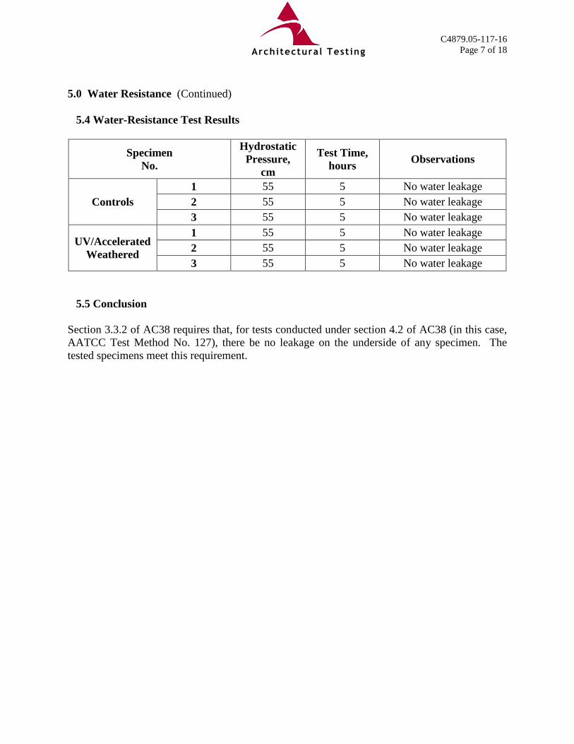
Photo No. 1 TamlynWrap® Product
Photo No. 2 ASTM E 96 Water Vapor Transmission Test
Architectural Testing

C4879.05-117-16
Photo No. 3 ASTM E 2178 Air Permeance Test
Photo No. 4 Specimens Undergoing AATCC Test
Method No. 127 Hydrostatic Head Testing
Architectural Testing

C4879.05-117-16
Photo No. 5 ASTM E 2273 Drainage Efficiency Test
Architectural Testing

C4879.05-117-16
Photo No. 6 Installation of ASTM E 2273 Specimen
Architectural Testing

C4879.05-117-16
Photo No. 7 ASTM E 2273 Specimen
Architectural Testing

C4879.05-117-16
APPENDIX C
Manufacturer's Declaration
Architectural Testing

Friday, February 01, 2013 Tamlyn as agreed to allow Architectural Testing Inc. to test our TamlynWrap™ Drainable House Wrap. As a senior manager of Tamlyn, I certify that the product tested is representative of the standard manufactured product to be covered in the evaluation report. Reference: AC 148 Testing for Thru-Wall Flashing Best regards,
Miguel Gonzales, Sr. VP

C4879.05-117-16
APPENDIX D
Air Permeance Actual Pressure and Flow Values
Architectural Testing

C4879.05-117-16
Specimen 1 - TamlynWrap™
Date/Time Target Pressure, Pa
Actual Pressure, Pa
Actual Flow, L/s
Tare (Leakage) 1/28/2013 10:20 25 24.9502 0.00176 1/28/2013 10:49 50 50.25129 0.00255 1/28/2013 10:56 75 75.01339 0.00425 1/28/2013 11:01 100 100.10756 0.00541 1/28/2013 11:08 150 150.36594 0.00737 1/28/2013 11:13 300 300.73160 0.01301
Test 1/28/2013 12:27 25 25.06192 0.00217 1/28/2013 12:47 50 50.14501 0.00397 1/28/2013 12:59 75 75.32734 0.00607 1/28/2013 13:06 100 99.97887 0.00798 1/28/2013 13:12 150 150.38000 0.01177 1/28/2013 13:22 300 301.12423 0.02032
Specimen 2 - TamlynWrap™
Date/Time Target Pressure, Pa
Actual Pressure, Pa
Actual Flow, L/s
Tare (Leakage) 1/28/2013 15:39 25 25.11451 0.00137 1/28/2013 15:56 50 50.17493 0.00245 1/28/2013 16:07 75 75.37404 0.00385 1/28/2013 16:16 100 100.17693 0.00486 1/28/2013 16:23 150 150.41341 0.00699 1/28/2013 16:30 300 300.95753 0.01226
Test 1/28/2013 16:51 25 25.09721 0.00263 1/28/2013 17:02 50 50.1676 0.00499 1/28/2013 17:10 75 75.19175 0.0075 1/28/2013 17:18 100 100.16167 0.00953 1/28/2013 17:24 150 150.46326 0.01356 1/28/2013 17:32 300 301.27465 0.02382
Architectural Testing

C4879.05-117-16
Specimen 3 - TamlynWrap™
Date/Time Target Pressure, Pa
Actual Pressure, Pa
Actual Flow, L/s
Tare (Leakage) 1/29/2013 9:47 25 25.10198 0.00101 1/29/2013 10:04 50 50.21566 0.00108 1/29/2013 10:23 75 75.25703 0.00137 1/29/2013 10:34 100 100.10202 0.00227 1/29/2013 10:41 150 150.35801 0.00295 1/29/2013 10:47 300 301.15925 0.00487
Test 1/29/2013 11:28 25 25.02434 0.00137 1/29/2013 11:37 50 50.22785 0.00324 1/29/2013 11:46 75 75.26888 0.00495 1/29/2013 11:52 100 99.93532 0.00672 1/29/2013 11:59 150 149.86262 0.00937 1/29/2013 12:09 300 301.03883 0.0164
Specimen 4 - TamlynWrap™
Date/Time Target Pressure, Pa
Actual Pressure, Pa
Actual Flow, L/s
Tare (Leakage) 1/29/2013 15:22 25 25.03124 0.00019 1/29/2013 15:36 50 50.21319 0.00046 1/29/2013 15:47 75 75.27723 0.00072 1/29/2013 15:56 100 99.92816 0.00108 1/29/2013 16:05 150 150.39849 0.00107 1/29/2013 16:11 300 301.19786 0.00234
Test 1/29/2013 16:54 25 25.10172 0.00052 1/29/2013 17:07 50 50.21728 0.00108 1/29/2013 17:27 75 75.32998 0.00137 1/29/2013 17:35 100 100.31652 0.00222 1/29/2013 17:42 150 150.51644 0.00282 1/29/2013 17:47 300 301.02409 0.00563
Architectural Testing

C4879.05-117-16
Specimen 5 - TamlynWrap™
Date/Time Target Pressure, Pa
Actual Pressure, Pa
Actual Flow, L/s
Tare (Leakage) 1/30/2013 12:38 25 25.10027 0.00115 1/30/2013 13:07 50 50.01795 0.00159 1/30/2013 13:17 75 74.74161 0.00203 1/30/2013 13:30 100 100.1748 0.00251 1/30/2013 13:38 150 149.33407 0.00331 1/30/2013 13:46 300 299.55423 0.00566
Test 1/30/2013 14:06 25 25.01258 0.00155 1/30/2013 14:23 50 49.62806 0.00236 1/30/2013 14:35 75 75.27774 0.00305 1/30/2013 14:55 100 100.20002 0.00448 1/30/2013 15:02 150 149.46335 0.00605 1/30/2013 15:08 300 301.20604 0.01034
1/2" Drywall
Date/Time Target Pressure, Pa
Actual Pressure, Pa
Actual Flow, L/s
Tare (Leakage) 4/12/2013 10:27 25 25.06746 0.00153 4/12/2013 10:35 50 50.12004 0.00329 4/12/2013 10:46 75 75.31226 0.00476 4/12/2013 10:54 100 99.77451 0.00654 4/12/2013 11:00 150 150.47596 0.00919 4/12/2013 11:10 300 301.26076 0.01683
Test 4/12/2013 12:03 25 25.01710 0.00474 4/12/2013 12:16 50 49.88117 0.00864 4/12/2013 12:28 75 74.88513 0.01269 4/12/2013 12:44 100 100.42543 0.01671 4/12/2013 12:51 150 149.89960 0.02411 4/12/2013 12:59 300 299.73670 0.04580
Architectural Testing

C4879.05-117-16
APPENDIX E
Air Permeance Graph
Architectural Testing

C4879.05-117-16
Err
or A
naly
sis:
In
com
plia
nce
with
Sec
tion
9.4
an e
rror
ana
lysi
s sh
all b
e pe
rfor
med
that
incl
udes
an
exam
inat
ion
of th
e so
urce
s of
err
or, a
n ev
alua
tion
of s
yste
mat
ic e
rror
s an
d pr
opag
atio
n of
err
or, a
nd th
e re
sulti
ng v
alue
of
erro
r on
air
flow
va
lues
thro
ugh
the
mat
eria
l tes
ted.
The
regr
essi
on a
naly
sis
yiel
ded
a m
uch
low
er c
orre
latio
n th
an th
e m
etho
d al
low
s. O
ne
cont
ribut
ing
fact
or is
bel
ieve
d to
be
the
low
air
flow
thro
ugh
the
test
spe
cim
ens.
Sm
all d
iffer
ence
s in
flo
w b
etw
een
low
flo
w t
est
spec
imen
s w
ill c
ause
a l
arge
diff
eren
ce i
n co
rrel
atio
n.
The
othe
r co
ntrib
utin
g fa
ctor
is
belie
ved
to b
e th
e te
st
spec
imen
s th
emse
lves
. Im
perf
ectio
ns s
uch
as s
mal
l hol
es in
the
mat
eria
l may
cau
se a
ir le
akag
e an
d th
e m
ater
ial c
ould
be
non-
hom
ogen
ous d
ue to
the
man
ufac
turin
g pr
oces
s.
Architectural Testing