Embed Size (px)
Citation preview


2
CONTENTSAC SYNCHRONOUS MOTORS
Construction and Principles of Operation 3-4
Introduction 4
Principle Advantages 4
Identification System 4-5
Single Phase Operation 5-6
Starting and Stopping Characteristics 6
Starting in the Desired Direction 6
Starting and Running Current 7
Stalling Causes No Damage 7
Torque Versus Voltage 7
Speed Versus Frequency 8
Two-Phase or Three-Phase Operation 8-9
Starting High Inertial Loads 9
Parallel Motor Operation 9
Holding Torque 10
Effect of Gearing 11
The Selection Process 11-13
Capabilities 13
AC Applications 14
SL-4003-1 Printed in U.S.A. PRICE $2.00

3
AC SYNCHRONOUS MOTORS1.0 CONSTRUCTION AND PRINCIPLES OF OPERATIONThe SLO-SYN motor is unique in that it has the capability of being operated as anAC synchronous, constant speed motor or as a phase switched DC stepper motor.In either case, it is classified as a permanent magnet inductor motor.
Figure 1 shows the simplicity of the basic motor construction. Note that the motorhas no brushes, commutators, belts or slip rings. Essentially, the motor consists ofa rotor and a stator which make no physical contact at any time, due to a carefullymaintained air gap. As a result of the simple construction, the motor provides longlife and high reliability. A continuous running life of five years can be expected.
FIGURE 1In a typical 72 rpm mo-tor, the stator has eightsalient poles with a two-phase, four-pole wind-ing (see Figure 2). Polesdesignated N1, S3, N5and S7 are energizedby one phase, whilePoles N2, S4, N6 andS8 are controlled by theopposite phase.
The stator teeth are setat a pitch of 48 teeth fora full circle, althoughthere are actually only40 teeth, as one toothper pole has been elimi-nated to allow space forthe windings. The wind-ings of each four alter-nate poles are con-nected in series. FIGURE 2
SHAFT MOUNTED ON TWOPRELUBRICATED, HIGHQUALITY BALL BEARINGS.NO LUBRICATION REQUIREDFOR LIFE OF MOTOR
GROUND NON MAGNETICSTAINLESS STEEL SHAFT
PRECISION MACHINEDCASE SEALS OUTDUST AND OTHERFOREIGN MATTER
THREE-LEAD CONNECTIONPERMITS SIMPLIFIEDSWITCHING
ROTOR HAS NEITHERCOMMUTATOR NORWINDINGS. NO MAIN-TENANCE NEEDED
STATOR/ROTOR ASSEMBLYSPECIALLY DESIGNED FORCONCENTRICITY

4
The rotor shown in Figure 3 consists of a nonmag-netic drive shaft, and an axially magnetized perma-nent magnet. The splines, or teeth, of the polepieces are offset by one-half a tooth pitch to permitthe use of a common stator magnetic structure andwindings.One pole piece is a south pole and theother, a north pole. FIGURE 3
Unlike the stator teeth, rotor teeth of a typical motor are at a pitch of 50 teeth for afull circle, two more than in the stator. Because of this difference, only two rotor teethand two stator teeth can be perfectly aligned simultaneously. The magneticarrangement of the rotor creates a south pole over the entire periphery of one-halfof the rotor and a north pole over the other half. An amount of residual, orunenergized, torque is provided in the rotor, which results in the motor having theability to stop instantaneously.
2.0 INTRODUCTIONA SLO-SYN motor operating from AC power is an extremely effective method ofobtaining precise motion control. Operation simply involves connecting the SLO-SYN motor to the AC power line, incorporating a phase shifting network consistingof a resistor/capacitor or just a capacitor, and using a three-position switch “forward”,“off” and “reverse” control. The phase shifting network provides the capacitivereactance necessary to produce a 90° phase shift between the two windings.
2.1 PRINCIPAL ADVANTAGES OF THIS TYPE OF MOTOR ARE ASFOLLOWS:1. Simple circuitry2. Bidirectional control3. Instantaneous start, stop and reverse4. Starting and running current are identical5. Stalling causes no damage6. Torque can be increased by increasing voltage7. Residual (Power Off) torque is always present8. Holding torque can be increased by applying DC voltage9. Long life and exceptional reliability
We will now discuss these features along with other aspects of the the SLO-SYNAC Synchronous Motor in more detail.
2.2 AC IDENTIFICATION SYSTEMThe type number identification system for SLO-SYN Synchronous Motors isstraightforward and easily understood. For example, in type number SS25, the “SS”indicates “Standard SLO-SYN”, which has a synchronous shaft speed of 72 rpm at120 volts, 60 hertz. The “25” in the type number designates the torque rating of themotor in ounce-inches. Figure 4 shows the letter designations which are offered andFigure 5 shows how the two elements of the type number identify the characteristicsof the motor.
Understanding the motor identification system makes it easy to select the correcttype number. For example, if an application requires a synchronous motor with a

5
AC SYNCHRONOUS MOTORSspeed of 72 rpm and a torque output of 200 ounce-inches at 120 volts, 60 hertz, theSS221 motor, which produces 220 ounce-inches of torque at 72 rpm, could bespecified. Consult the SLO-SYN motor catalog for a complete description of themotor identification system and a list of the motors available.
AC IDENTIFICATION SYSTEM Type Speed (rpm @ 60 Hertz) KS/SS 72 TS 200
FIGURE 4
IDENTIFICATION SYSTEM EXAMPLE SS 25
Torque in oz-in
72 rpmFIGURE 5
2.3 SINGLE-PHASE OPERATIONFigure 6 contains a diagram showing the connections for operating a SLO-SYNmotor as a three-lead, reversible motor from a single-phase source. Since a SLO-SYN motor is inherently a two-phase or a three-phase device, depending on model,a phase shifting network is required to convert the single-phase excitation into thetwo- or three-phase excitation required. Two-phase motors require a resistor anda capacitor for the phase-shifting network, while three-phase motors need only acapacitor. The connections in Figure 6 are for a two-phase motor.
Specific phase shifting component values are required for each motor and thesevalues are from published Ratings and Specifications charts in our catalog. Unlessotherwise specified, the component values listed in the catalog will providesatisfactory operation at any frequency between 50 and 60 hertz. Different valuesmay be necessary at other frequencies to give the required 90° phase shift. It mayalso be necessary to adjust the applied voltage level.
FIGURE 6
RED
R
C
1A
2
3 B
OFF
CW
CCW
AC LINEBLACK
WHITE
PHASE B
PHASE A
90°

6
“Tuning” the phase-shifting by adjusting the component values can help achievemaximum torque, minimum vibration, or any combination thereof. The correctphase-shifting component values are necessary for proper operation of the motor.Without the proper values, motor direction will be completely random. There will alsobe a tendency to reverse in response to even slight load changes and, at times, themotor may fail to start. Incorrect phase-shifting component values will also causeerratic, unstable operation.
The Phase-shifting network components are normally mounted externally. Certainmotor models are available with the components mounted in a housing on the rearof the motor. Consult the catalog for availability of these models.
2.4 STARTING AND STOPPING CHARACTERISTICSVirtually instant starting and stopping characteristics are among the principaladvantages of a SLO-SYN motor. Generally, the motor will start within 1-1/2 cyclesof the applied frequency and will stop within 5 mechanical degrees. Figure 7 showsa typical starting curve for a 72 rpm SLO-SYN motor. The motor will start and reachits full synchronous speed within 5 to 25 milliseconds. The unusually short stoppingdistance of a SLO-SYN motor is obtained by simply deenergizing the motor. Nomechanical or electrical braking is necessary. The quick stopping is the result of theslow rotor speed and the presence of a no-load reluctance torque produced by thepermanent magnet and the tooth construction of the stator and rotor.
FIGURE 7
2.5 STARTING IN THE DESIRED DIRECTIONThe two conditions which determine the instantaneous starting direction of a SLO-SYN motor are the position of the rotor prior to start and what portion of the AC sinewave is apparent when it is first applied to the motor windings. Curve A in Figure7 shows the motor starting in the correct direction. The motor may also momentarilystart in the wrong direction, then quickly reverse and rotate in the correct direction(Curve B in Figure 7). In most instances, this action is negligible and is of noconsequence. The motor will still start within the 25 milliseconds stated earlier. Inapplications where no motion in the opposite direction can be tolerated, externalcontrol circuits employing “Zero Crossover” techniques must be used.
A B
5 25
72RPM
TIME (MS)
SPEE
D (R
PM)

7
AC SYNCHRONOUS MOTORS2.6 STARTING AND RUNNING CURRENTBecause of the nature of the permanent magnet inductor motor, there is no highinrush current when power is applied. The windings are excited by the alternatingcurrent, with no current being conducted through the rotor or through brushes.Because energization of the SLO-SYN motor merely involves energizing thewindings, the starting, running and stall currents are, for all practical purposes,identical. Therefore the engineer designing a system need not be concerned abouthigh inrush currents with the SLO-SYN motor. Consult the motor catalog for currentrequirements of the various SLO-SYN motor models
2.7 STALLING CAUSES NO DAMAGEBecause of the characteristics described in Section 2.6, a SLO-SYN motor does notdraw excessive current when the motor is stalled. Since the windings are merelybeing energized by the alternating current, it doesn’t matter whether the rotor is inmotion or at a standstill. Also, no detrimental overheating will take place. Therefore,if this motor were used in an application in which it was operating a remotelycontrolled valve, and the motor stalled, there would be no possibility of systemdamage due to overheating of the motor, etc. One precaution must be noted: in thisstalled condition, the motor will oscillate severely, eventually causing bearingfailure.
2.8 TORQUE VERSUS VOLTAGEAs shown in Figure 8, the torque outputof a SLO-SYN motor is linearly propor-tional to the applied voltage.Primarilyfor intermittent operation, this capabil-ity can be used to increase the torqueoutput by increasing the voltage. Forexample, assume the steady-statetorque requirement for a given appli-cation is 110 ounce-inches. Normallya standard 130 ounce-inch motor wouldbe adequate for the application. If, how-ever, the application is subject to widevariations in line voltage, the 20 ounce-inch safety margin may be inadequate.A simple solution is to increase linevoltage by approximately 10 volts witha step-up transformer or a POWERSTAT® Variable Transformer. Because operationat higher than rated voltage will cause an increase in motor temperature rise, themotor shell temperature must be monitored and must not be permitted to go above100° C. Obviously, where more torque is needed, the next larger motor size shouldbe used. The torque/voltage relationship should only be used to increase torquewhen a larger motor will not fit into the space available.
200(14.4)
17.5(12.6)
125(9.00)
150(10.8)
100(7.20)
75(5.40)
50(3.60)
25(1.80)
000 20 40 60 80 100 120 140
INPUT VOLTS
TORQ
UE
OZ
- IN
(KPC
M)
TYPICAL TORQUE VS.VOLTAGECURVE FOR AC OPERATION
OF A SLO-SYN MOTOR
8
2.9 SPEED VERSUS FREQUENCYThe speed of a SLO-SYN motor is directly proportional to the applied frequency.Because the winding impedance is also a function of frequency, a constant-torqueoutput will only be obtained at different excitation frequencies by varying linevoltage, as shown in Figure 9. Only when the motor is operating from a two-phaseor three-phase supply (depending on motor model) can different synchronousspeeds be easily achieved by varying the line frequency.
When varying the frequency of a single-phase system, the phase shifting compo-nent values must be changed to provide thenecessary 90° phase shift at each newoperating frequency. Figure 10 shows thespeeds at different frequencies for the twostandard SLO-SYN motor series.
FIGURE 9
FREQUENCY KS/SS TS (HERTZ) SERIES SERIES
10 12 33.4 20 24 66.8 30 36 100.2 40 48 133.6 50 60 167.0
60 72 200.0
70 84 233.8 80 96 267.2 90 108 300.6
100 120 334.0
FIGURE 10
3.0 TWO-PHASE OR THREE-PHASE OPERATIONIn some applications, SLO-SYN AC Synchronous Motors are operated directly froma two-phase or a three-phase source. Connections for two-phase motor operatedfrom a two-phase supply are shown, no phase-shifting network is needed as longas the supply provides the necessary phase shift between the windings (90° for two-phase motors; 120° for three-phase motors). From 0 hertz to approximately 100hertz, motor speed can be varied by simply changing the supply frequency. Thechart in Figure 10 shows the speeds obtainable at different frequencies for the SSand TS series of motors. Depending on the motor used and the torque and inertiarequirements, a motor may fail to start at frequencies above 100 hertz. Note that, as
200
100
150
50
00 20 40 60 80 100
FREQUENCY (HERTZ) - 2 PHASE SUPPLY
VO
LTS
PER
PHA
SEVOLTAGE VERSUS FREQUENCY
FOR A SLO-SYN MOTOR

9
AC SYNCHRONOUS MOTORSshown in Figure 9, voltage must be ad-justed as frequency is changed.
3.1 STARTING HIGH INERTIAL LOADSBecause of the rapid starting characteristics of a SLO-SYN motor, a maximummoment of inertia value is listed for each motor model. These values represent themaximum inertial load which specific motor models can start when driving the loadthrough a rigid coupling. Inertial loads five to ten times these values can be startedby using a flexible coupling between the motor shaft and the load. The flexiblecoupling should allow approximately 5° of flex before the full inertial load is “seen”by the motor shaft. The coupling can be as simple as a rubber coupling betweenthe motor and the load, or it could be a chain with sufficient slack. Timing belts arealso used as load coupling devices and, in many cases, will provide sufficient flexas well as serve as a smooth and quiet power transmission device. Figure 12 showstwo typical flexible couplings.
FIGURE 12
3.2 PARALLEL MOTOR OPERATIONAny number of SLO-SYN motors may be operated in parallel if their total currentrequirement does not exceed that of the power supply. It is important to realize,however, that due to the starting characteristics of this type of motor, mechanicalsynchronization of parallel operated motors is not practical. As mentioned earlier,the two conditions that determine the direction of rotation are the position of the rotorprior to start and the portion of the sine waveform apparent when the voltage isapplied. Because of these variables, one motor may start within a 5 millisecondperiod, while another motor operated in parallel with the first may take up to 25milliseconds to start. This will occur because the rotor of the second motor was ina slightly different position at the start of the cycle. This situation was previouslyillustrated in Figure 7.
Typical Wiring for OperationFrom a Two-Phase Source
FIGURE 11
SETSCREWS
RUBBER INSERT
SETSCREWS
STEEL SLEEVES
RUBBER SLEEVEBONDED
SETSCREW
MATING FINGERS
RED
1
2
3
MOTOR
BLACK
WHITE

10
3.3 HOLDING TORQUESome applications require more holding torque than the small residual torqueprovided by the permanent magnet rotor. To increase the holding torque, DC volt-age can be applied to one or both motor windings when the motor is in the off con-dition. Connections which can be used to accomplish this are shown in Figure 13.
With DC voltage applied to onewinding, the holding torque willbe increased approximately20% over the rated torque ofthe motor. When DC voltage isapplied to both motor wind-ings, holding torque will beapproximately 1-1/2 times therated torque.
When DC voltage is applied tothe windings, the motor mayjump into a position of maxi-mum magnetic attraction. Thedegree of movement dependson the position of the rotor rela-tive to the stator when the DCvoltage is applied and can be up to ±3.6° for an SS series motor. Figure 14 showsthe holding torque available for various motor models when DC voltage is applied.
FIGURE 14
RED
R
C
1
2
3
OFF
CW
CCW
ACLINE
BLACK
WHITE
DCSUPPLY
RELAY
TYPICAL CIRCUIT FORAPPLYING DC VOLTAGETO INCREASEHOLDING TORQUE
FIGURE 13

11
AC SYNCHRONOUS MOTORS3.4 EFFECT OF GEARINGThe use of gearing with a SLO-SYN motor allows a reduction in speed and anincrease in output torque when gearing down. Under “gearing down” conditions,torque is increased and output speed decreased by the factor of the gear ratio. Forexample, an SS91 motor produces 90 ounce-inches of torque at 72 rpm. If 4:1 step-down gearing is used between the motor and the load, the motor output torque wouldbe approximately 360 ounce-inches at a speed of 18 rpm.
The mechanical advantage of gearing is most apparent in dealing with inertia asthe inertia moving capability is affected by the square of the gear ratio. Again,assume 4:1 step-down gearing is being used with an SS91 motor. The SS91 hasa maximum moment of inertia capability of 1.6 lb-in2. With 4:1 gearing, however, themaximum moment of inertia is increased 16 times and would become approxi-mately 25.6 lb-in2 (42 = 16 x 1.6 lb-in2).
Timing belts and pulleys are also widely used and provide a “softer” coupling withthe same overall effect as steel gearing. Some SLO-SYN motors are available with“in-line” planetary type gearheads. A complete listing of these “SLO-SYN ACGearmotors” can be found in the motor catalog.
3.5 THE SELECTION PROCESSSelecting the correct AC synchronous motor for a particular application is a relativelysimple task. The most important parameters are:
1. Speed (rpm)2. Torque (ounce-inches)3. Inertia (lb-in 2)
Since the standard available speeds of SLO-SYN motors are 72 and 200 rpm, thetwo key variables become torque and inertia. Of the two, inertia has always beenthe least understood parameter and one that often serves as a “trap” if overlooked.For example, assume an application requires 35 ounce-inches torque and theinertia is 2 lb-in2. A typical initial reaction is to select an SS91 motor, rated at 90ounce-inches, simply because the application requires only 35 ounce-inchestorque. However, the SS91 motor is only capable of moving 1.6 lb-in2. Therefore,the SS91 motor would be unable to start the load. For this application as described,the best choice would be the SS221 motor, which provides 220 ounce-inches oftorque and is rated for a maximum moment of inertia of 2.5 lb-in2.

12
As can be seen from this example, it is important to know the maximum moment ofinertia which will be reflected to the motor. Only when all the parameters are knowncan an intelligent decision be made in selecting the correct motor for the application.Formulas for calculating torque and inertia are follow.
a. TORQUE (oz-in) = Frwhere F = Force (in ounces) required to drive the load r = Radius (in inches)
Force can be measured using a pull type spring scale. The scale may be attachedto a string that is wrapped around a pulley or handwheel attached to the load. If thescale reading is in pounds, it must be converted into ounces to obtain a torque valuein ounce-inches.
For example, a 4” diameter pulley requires a 2 pound pull on the scale to rotate it.
F = 2 pounds x 16 = 32 ounces
4”r = = 2”
2
TORQUE = 32 x 2 = 64 ounce-inches
b. MOMENT OF INERTIA
Wr2
(lb-in2) = for a disc 2
W or (lb-in2) = (r1
2 + r22) for a cylinder
2
where W = Weight (in pounds)r = Radius (in inches)
For example, a load is a 8” diameter gear weighing 8 ounces
8W = = 0.5 pound
16
8”r = = 4”
2
0.5 x (4)2
MOMENT OF INERTIA = = 4 (lb-in2) 2

13
AC SYNCHRONOUS MOTORSGEARS AND PULLEYSWhen the load is to be driventhrough gears or pulleys, thetorque should be decreasedor increased by the overallratio. For example, if the loadis 90 ounce-inches and it is tobe driven through a step-downratio of 3:1, the required torqueis 30 ounce-inches.
Load inertia should be de-creased or increased by thesquare of the ratio. For ex-ample, with a load inertia of 4pound-inches2 and a 2:1 step-down ratio, the effective iner-tia would be 1 pound-inch2
plus the inertia of the first gearor pulley.
INERTIA CONVERSION FACTORSslug-ft2 x 4600 = lb-in2
lb-ft2 x 144 = lb-in2
oz-in2 x 0.0625 = lb-in2
lb-ft-sec2 x 4600 = lb-in2
lb-in-sec2 x 384 = lb-in2
oz-in-sec2 x 24 = lb-in2
gm-cm2 x 0.000342 = lb-in2
kp-m-sec2 x 33,500 = lb-in2
3.6 CAPABILITIESSLO-SYN AC Synchronous Motors produce torque outputs ranging from 25 ounce-inches to 1800 ounce-inches in various frame sizes. In addition to the wide varietyof torque ratings and frame sizes, special capability motors such as double-endedshaft, militarized, limited vacuum, high temperature, radiation resistant, dust-ignition proof and explosion-proof types are available.
Gearmotors and motors with phase-shifting components are also offered on somemodels.
METRIC-DECIMAL EQUIVALENTS1 inch = 2.54 cm1 cm = 0.3937 inch1 pond (gm) = 0.03527 oz1 oz = 28.35 pond (gm)1 kp (kg) = 2.205 pound1 gm-cm = 0.0139 oz-in1 kg-cm = 1 kp-cm = 13.9 oz-in1 hp = 746 watts
14
3.7 AC APPLICATIONSSLO-SYN AC Synchronous Motors provide low, constant-speed positioning controlwith minimum control circuitry and maximum life. The following is a partial list ofpossible applications.
a. Valve controls k. Tape dispensersb. Timing belt drives l. Remote control of switches, rheostats, etc.c. Conveyor systems m. X-Y positioningd. Card positioning n. Textile edge guide controlse. X-Ray scanning o. Printing press ink pump controlf. Antenna rotators p. Generatorsg. Film handling q. Automated welding equipmenth. Microfilm scanners r. Paper handlingi. Paper feed s. Medical pumpsj. Furnace damper controls t. Fluid metering

15
AC SYNCHRONOUS MOTORS
DISTRIBUTION COAST-TO-COASTAND INTERNATIONAL
Superior Electric SLO-SYN products are available nationwide through anextensive authorized distributor network. These distributors offer literature,technical assistance and a wide range of models off the shelf for fastestpossible delivery and service.
In addition, Superior Electric sales engineers and manufacturers' representa-tives are conveniently located to provide prompt attention to customers'needs. Call Superior Electric customer service for ordering and applicationinformation or for the address of the closest authorized distributor for SuperiorElectric's SLO-SYN products.
IN U.S.A. and CANADA383 Middle StreetBristol, CT 06010Tel: (860) 585-4500FAX: 860-589-2136Customer Service: 1-800-787-3532Product Application: 1-800-787-3532FAX: 1-800-766-6366Product Literature Request: 1-800-787-3532Web Site: www.superiorelectric.com
IN EUROPEWarner Electric (Int.) Inc.La PierreireCH-1029 Villars-Ste-Croix, SwitzerlandTel: 41 21 631 33 55Fax: 41 21 636 07 04

1
DC STEPPING MOTORS

2
CONTENTS
Page
Purpose 3
Basic Description 3
Stepper Motor Technology 3-5
Step Angle 5
Basic Construction and Operation 5-6
Ratings 6-8
The Four-Step Switching Sequence 9
The Eight-Step Switching Sequence 9
Torque-Speed Relationship 9
Steps Per Second/RPM Conversions 10
Handling Inertial Load 10-11
Holding Torque Vs. Torque At Standstill 11
Ratings and Specifications 12
Damping 13
Resonance 14
Lanchester Dampers 14
Encoder Motors 15
Special Capability Motors 16
Information Required 16-17
Formulas 17-24
Selecting, Inch Units 25-26
Selecting, Metric Units 27-28
Applications 28-29
The Electronic Drive 30
L/R Unipolar Drives 30
L/R Bipolar Drives 30
Two-Level Drives 30
Reactive Drives 30
Chopper Drives 30
Translators 31
Indexers 31
The Drive Selection Process 31
SL4003-1 PRINTED IN U.S.A.

3
DC STEPPING MOTORS
1.0 PURPOSEThe purpose of this guide is to acquaint the designer with basic characteristics ofDC stepper motors and associated drives. Their advantages and capabilities asdigital motion control devices are also discussed.
1.1 BASIC DESCRIPTIONThe stepper motor is a device which translates electrical pulses into mechanicalmovements. The output shaft rotates or moves through a specific angular rotationfor each incoming pulse or excitation. This angle or displacement per movementis repeated precisely with each succeeding pulse translated by appropriate drivecircuitry. The result of this precise, fixed and repeatable movement is the ability toaccurately position. Unlike a conventional motor, which has a free running shaft, thestepper motor shaft rotates in fixed, repeatable, known increments. The steppermotor therefore allows control of load velocity, distance and direction. Initialpositioning accuracy of a load being driven by a stepper motor is excellent. Therepeatability (the ability to position through the same pattern of movements amultiple number of times) is even better. The only system error introduced by thestepper motor is its single step error, which is generally less that 5% of one step. Mostsignificantly, this error is noncumulative, regardless of distance positioned ornumber of times repositioning takes place. The stepper motor is generally controlledby a DC power supply and drive/logic circuitry which will be discussed in this guide.
1.2 STEPPER MOTOR TECHNOLOGYAs the use of stepper motor systems has increased in a broad base of applications,terminology has evolved which required definition.
A. Step Angle - This is the specific angular increment the motor shaft will moveeach time the winding polarity is changed. It is specified in degrees.
B. Steps Per Revolution - This term describes the total number of steps requiredfor the motor shaft to rotate 360°, or one complete revolution. The number iscalculated by dividing the step angle into 360°.
C. Steps Per Second - This is the number of steps accomplished by the motor inone second of time. This figure replaces the rpm value of a standard drive motor.See Section 7 for formulas used to calculate this value.
DESIGN ENGINEER'S GUIDETO
DC STEPPER MOTORS

4
D. Step Accuracy - Defined as positional accuracy tolerance. This value isgenerally expressed in percent and indicates the total error introduced by thestepper motors in a single step movement. The error is noncumulative, i.e., it doesnot increase as additional steps are taken. In a linear system with a resolution of0.001 inch, a 3% accuracy motor would introduce a maximum of 0.00003 inch errorinto the system. This total error would not accumulate or increase with total distancemoved or number of movements made.
E. Holding Torque - With the motor shaft at standstill (zero rpm condition), HoldingTorque is the amount of torque, from an external source, required to break the shaftaway from its holding position. It is measured with rated current and voltage appliedto the motor. Holding torque is a basic characteristic of stepper motors and providespositioning integrity under standstill, or rest, conditions.
F. Residual Torque - This is the torque present at standstill under power offconditions and is a result of the permanent magnetic flux acting on the stator poles.Residual torque is present under power off conditions only with a motor ofpermanent magnet rotor design.
G. Step Response - When given a command to take a step, a stepper motor willrespond within a specific time period. This time period, or "time for a single step",is a function of the torque-to-inertia ratio of the motor and of the characteristics ofthe electronic drive system. Ratings given are for no-load conditions and aregenerally expressed in milliseconds.
H. Torque-To-Inertial Ratio - This ratio is calculated by dividing the rated holdingtorque of the motor in ounce-inches by its rotor inertia in ounce-inch-secondssquared. The better the torque-to-inertia ratio, the better the step response. Whendealing with step response problems, it is important to know the torque-to-inertiaratio of the motor.
I. Resonance - Stepper motors are a "spring response" system and, as such, havecertain "natural" frequency characteristics. When a motor's natural frequency, or"resonance" is reached, an increase in the audible level of the motor's operation canbe detected. In cases of server resonance, the motor may lose steps and/or oscillateabout a point. The frequency at which this occurs depends on the motor and the load.In many applications, it may not occur to any perceptible degree. However, thedesigner should realize that this condition can exist and specific facts about theresonant characteristics of a particular motor should be obtained from the manu-facturer.
J. Drives - This a broad term used to describe the circuitry which controls the steppermotor. It usually consists of a power supply, sequencing logic and power outputswitching components. These drives are generally categorized as Translators,Translator/Oscillators or Indexers.
K. Translator - An electronic control with circuitry to convert pulses into the switchingsequence which will operate the motor one step for each pulse received. Translatorsusually have no counting capability.
L. Translator/Oscillator - Includes translator circuitry together with a built-inoscillator which can serve as a pulse source.
M. Indexer - An electronic control which includes the translator function plusadditional circuitry to control the number of steps taken as well as direction andvelocity.

5
DC STEPPING MOTORSN. Pulse Rate - The rate at which windings are switched. Where one pulse equalsone motor step, the pulse rate is also the motor stepping rate.
O. Ramping - This is the process of controlling the pulse frequency to acceleratethe motor from base speed to running speed as well as to decelerate the motor fromrunning speed to base speed. Ramping increases the ability to drive the motor andload to higher speeds, particularly with large inertial loads.
P. Slew Rate - An area of high speed where the motor can run unidirectionally insynchronism. However, it cannot start, stop or reverse at this rate. A stepper motoris brought to a slewing rate using acceleration and is then decelerated to stop underconditions where no step loss can be tolerated.
Q. Damping - Damping is defined as the reduction or elimination of step overshoot.It is used where settling down time is important,. Damping methods used includemechanical, electronic and viscous means.
1.3 STEP ANGLEThe step angle of a SLO-SYN Step Motor is 1.8°, equivalent to 200 steps perrevolution.
2.0 BASIC CONSTRUCTIONAND OPERATION
Operation of a stepper motor is relatedto basic permanent magnet theory,where "likes' repel and "opposites"attract. If the stator windings in Figure1 are energized such that Stator A isthe North Pole, Stator B is the SouthPole and the permanent magnet rotoris positioned with its polarity as shown,it is impossible to determine the direc-tion of rotation. However if, as shownin Figure 2, two additional Stator polesC and D are added and energized sothat polarities appear as shown, wewould then be able to dictate the direc-tion of rotor rotation. In this case, thedirection would be counterclockwisewith the rotor aligning itself betweenthe "average" South Pole and the "av-erage" North Pole, as shown in Figure3.
A
B
N
N
S
S
ROTOR
A
B
N
N
S
S
ROTORC DNS
FIGURE 1
FIGURE 2

6
To allow better single step resolution,four more stator poles are added andteeth are machined on each statorpole as well as on the rotor. In the finalanalysis, the number of teeth on therotor determines the step angle thatwill be achieved each time the polar-ity of one winding is changed. Therotor/stator tooth configuration for a1.8° stepper is shown in Figure 4.
3.0 RATINGSThe chart lists typical ratings for SLO-SYN Stepper Motors as shown in our catalogs.While the voltage rating is straightforward, note that the current requirements aregiven in "amperes per winding." Using the typical four-step switching sequence, twowindings are 'on' at any given time. Therefore, the total current requirement of themotor is twice the "amperes per winding" value given in the chart. Inductance andresistance values are also given "per winding."
A
B
N
N
S
S
ROTORC D
ROTOR NS
AVERAGESOUTH
AVERAGENORTH
FIGURE 3
FIGURE 4

7
DC STEPPING MOTORS
M o to r Typ eT ypical
T im eF or
S ing leS top(m S )
N o m in alD C
V olts
R atedA m peres
forW in d ing
N o m in alR esistan ce
P erW in d ing
(25°C )O hm s
N o m in alIn d uctan ceP er P h ase
(M il li-H en rys)
2%A ccu racy
3%A ccu racy
5%A ccu racy
U N IP O L A R R A TIN G S (6-LE A D D R I V E )
K M ~ 060S 03K M ~ 060S 08
— — —2.91.3
1.53.8
1.90 .34
4.00 .63
K M ~ 061S 02K M ~ 061S 04K M ~ 061S 08
— — —6.43.01.7
1.02.13.8
6.41.5
0 .46
183.51.1
K M ~ 062S 04K M ~ 062S 06K M ~ 062S 09
— — —3.12.81.8
2.13.04.7
1.50 .940 .38
4.22.5
0 .85
K M ~ 063S 04K M ~ 063S 09
— — —4.32.5
2.14.7
2.00 .54
6.01.6
K M ~ 091S 02K M ~ 091S 06K M ~ 091S 08K M ~ 091S 09
— — —
9.32.92.11.8
1.03.13.84.7
9.30 .940 .550 .38
474.72.91.9
K M ~ 092S 09 — — — 2.5 4.6 0 .54 2.8
K M ~ 093S 07K M ~ 093S 10
— — —4.43.5
3.54.8
1.30 .72
8.34.5
—M 061 -~ S 02M 061 -~ E 02
— 2.5 5.0 1.0 5.0 9 .57
—M 061 -~ S 08M 061 -~ E 08
— 2.0 1 .25 3.8 0 .33 0 .635
—M 062 -~ S 04M 062 -~ E 04
— 2.8 4.2 1.9 2.2 5 .89
—M 062 -~ S 06M 062 -~ E 06
— — 2.6 3.1 0 .88 2.0
—M 062 -~ S 09M 062 -~ E 09
— 2.2 1 .65 4.7 0 .35 0.8
— M 091 -F C 06 M 091 -~ S 06 3.9 2.6 3.1 0 .85 4 .12
— — M 091-~ E 06 3.9 2.6 3.1 0 .85 4 .12
— — M 091-~ E 09 3.1 1.7 4.7 0 .36 1.5
— — M 092-~ E 08 4.0 3.0 4.0 0 .75 3 .56
— — M 092-~ E 09 3.9 2.5 4.6 0 .55 2 .76
— — M 093-~ E 11 4.1 2 .64 5.5 0 .48 3 .19
— — M 093-~ E 14 3.4 2 .27 7.0 0 .324 2.0
— —M 111-F D 12
M 111 -F D -80124.4 2 .26 6.1 0 .37 2.3
— — M 112-F D 12 5.5 3 .66 6.1 0 .80 5.3
— — M 112-FJ -8012 5.5 3 .66 6.1 0 .60 5.3
~ = "L " f o r l e ads o r "T " f o r te rm i na l bo x
ELECTRICAL RATINGS

8
ELECTRICAL RATINGS
M oto r Typ eN o m inal
D CV olts
R atedA m peres
F orW in d ing
N o m inalR esist an ce
P erW in d ing
(25°C )O hm s
N o m inalIn d u ct an ceP er P h ase
(M il li-H en rys)
2%A ccu racy
3%A ccu racy
5%A ccu racy
4 - C O N N E C TIO N S T E P M O TO R S
K M ~ 0 6 0F 0 2K M ~ 0 6 0F 0 5K M ~ 0 6 0F 0 8K M ~ 0 6 0 F 11
— —
3 .81 .71 .11 .0
1 .12 .74 .05 .3
3 .60 .6 40 .2 80 .1 9
1 62 .51 .0
0 .6 3
K M ~ 0 61 F 0 2K M ~ 0 61 F 0 3K M ~ 0 61 F 0 5K M ~ 0 61 F 0 8K M ~ 0 6 1 F 11
— —
5 .24 .22 .31 .41 .2
1 .11 .42 .74 .15 .4
4 .93 .0
0 .8 50 .3 30 .2 3
3 01 6
4 .61 .81 .1
K M ~ 0 6 2F 0 3K M ~ 0 6 2F 0 5K M ~ 0 6 2F 0 7K M ~ 0 6 2F 0 8K M ~ 0 62 F 1 3
— —
4 .43 .12 .52 .01 .3
1 .52 .53 .34 .16 .6
2 .91 .3
0 .7 50 .4 90 .2 0
1 77 .13 .42 .5
0 .8 5
K M ~ 0 6 3F 0 3K M ~ 0 63 F 0 4K M ~ 0 6 3F 0 7K M ~ 0 6 3F 0 8K M ~ 0 63 F 1 3
— —
6 .15 .03 .42 .61 .9
1 .51 .83 .34 .16 .6
4 .12 .81 .0
0 .6 40 .2 8
2 41 7
6 .23 .91 .5
K M ~ 0 91 F 0 5K M ~ 0 91 F 0 7K M ~ 09 1 F 1 3
— —3 .02 .51 .3
2 .73 .36 .6
1 .10 .7 60 .1 9
117 .51 .9
K M ~ 0 9 2F 0 7K M ~ 0 92 F 1 3
— —3 .51 .7
3 .36 .5
1 .10 .2 7
112 .9
K M ~ 0 9 3F 0 7K M ~ 0 9 3F 0 8K M ~ 0 93 F 1 0K M ~ 0 93 F 1 4
— —
4 .94 .03 .22 .5
3 .44 .05 .16 .8
1 .40 .9 90 .6 30 .3 6
1 81 3
8 .34 .5
——
M 0 6 1 -~ F 0 1M 0 6 1 -~ F 0 2
——
8 .06 .3
0 .51 .0
1 5 .96 .3
6 1 .02 5
M 0 6 2-~ F 0 2M 0 6 2 -~ F 0 3
—6 .64 .2
1 .01 .5
6 .82 .8
3 3 .01 3
— M 0 6 3-~ F 0 3 — 5 .4 1 .5 3 .6 1 8 .0
— —M 0 9 1-~ F 0 2M 0 9 1 -~ F 0 6
6 .83 .0
1 .03 .0
6 .81 .0
5 2 .01 0
— —M 0 9 2-~ F 0 4M 0 9 2 -~ F 0 8
3 .44 .0
2 .04 .0
1 .71 .0
1 6 .611
— —M 0 9 3-~ F 0 6M 0 9 3 -~ F 0 8
4 .53 .9
3 .04 .0
1 .50 .9 6
1 6 .91 3
— —M 1 11 -F F -4 0 1M 1 11-F F -2 0 6
4 .03 .5
3 .45 .0
1 .1 40 .7 0
1 7 .79 .2
— — M X 11 1 -F F -4 0 1 U 4 .0 3 .4 1 .1 4 1 7 .7
— —M 11 2-F F -4 0 1M 11 2-F F -2 0 6
1 .9 53 .0
4 .06 .0
0 .4 90 .4 9
8 .8 08 .8 0
— — M X 11 2 -F F -4 0 1 1 .9 5 4 .0 0 .4 9 8 .8 0
— — M 11 3-F F -4 0 1 4 .5 6 .0 0 .7 5 1 7
~ = "L " f o r l e a d s o r "T" fo r te rm i n a l b o x
9
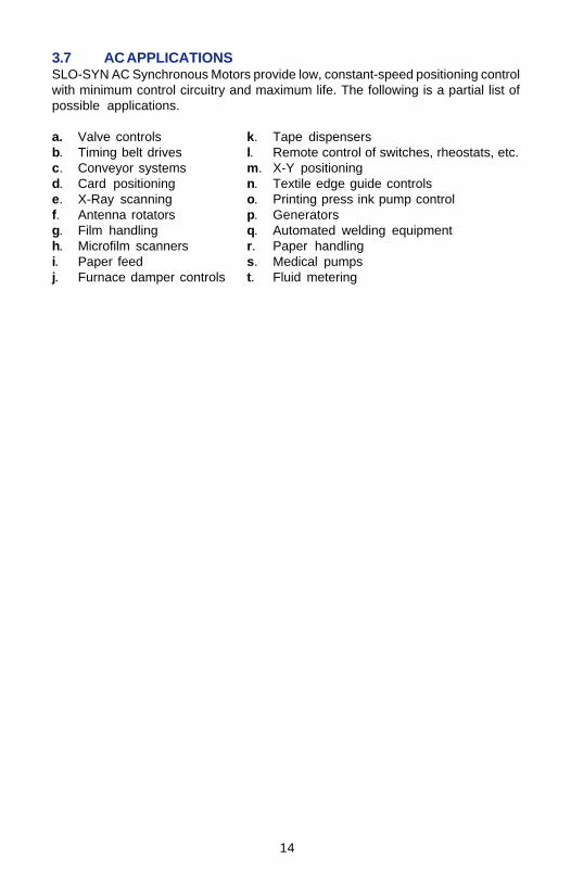
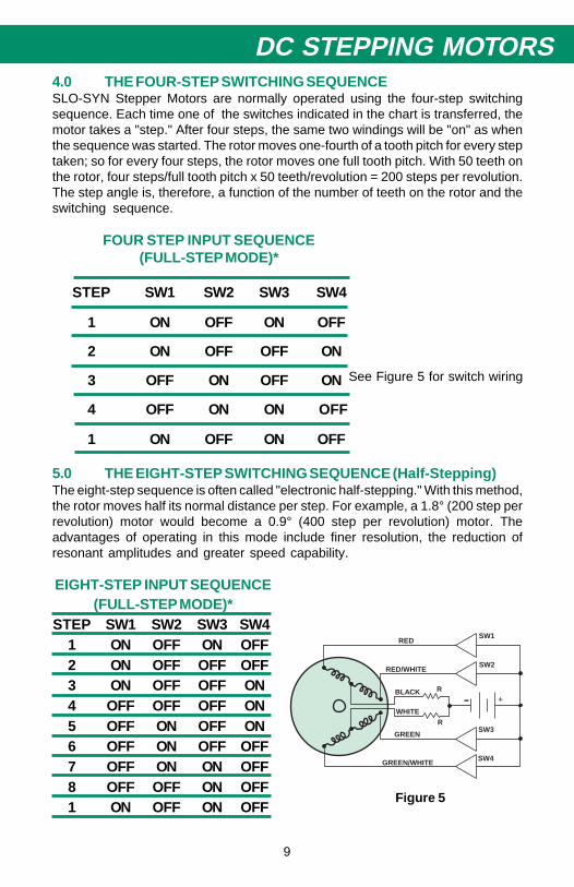
DC STEPPING MOTORS4.0 THE FOUR-STEP SWITCHING SEQUENCESLO-SYN Stepper Motors are normally operated using the four-step switchingsequence. Each time one of the switches indicated in the chart is transferred, themotor takes a "step." After four steps, the same two windings will be "on" as whenthe sequence was started. The rotor moves one-fourth of a tooth pitch for every steptaken; so for every four steps, the rotor moves one full tooth pitch. With 50 teeth onthe rotor, four steps/full tooth pitch x 50 teeth/revolution = 200 steps per revolution.The step angle is, therefore, a function of the number of teeth on the rotor and theswitching sequence.
FOUR STEP INPUT SEQUENCE(FULL-STEP MODE)*
STEP SW1 SW2 SW3 SW4
1 ON OFF ON OFF
2 ON OFF OFF ON
3 OFF ON OFF ON
4 OFF ON ON OFF
1 ON OFF ON OFF
5.0 THE EIGHT-STEP SWITCHING SEQUENCE (Half-Stepping)The eight-step sequence is often called "electronic half-stepping." With this method,the rotor moves half its normal distance per step. For example, a 1.8° (200 step perrevolution) motor would become a 0.9° (400 step per revolution) motor. Theadvantages of operating in this mode include finer resolution, the reduction ofresonant amplitudes and greater speed capability.
EIGHT-STEP INPUT SEQUENCE(FULL-STEP MODE)*
STEP SW1 SW2 SW3 SW41 ON OFF ON OFF2 ON OFF OFF OFF3 ON OFF OFF ON4 OFF OFF OFF ON5 OFF ON OFF ON6 OFF ON OFF OFF7 OFF ON ON OFF8 OFF OFF ON OFF1 ON OFF ON OFF
See Figure 5 for switch wiring
- +BLACK
WHITE
GREEN
RED/WHITE
GREEN/WHITE
REDSW1
SW2
SW3
SW4
R
R
Figure 5
10
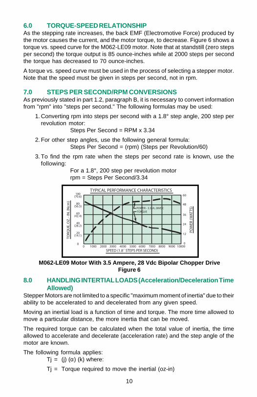
6.0 TORQUE-SPEED RELATIONSHIPAs the stepping rate increases, the back EMF (Electromotive Force) produced bythe motor causes the current, and the motor torque, to decrease. Figure 6 shows atorque vs. speed curve for the M062-LE09 motor. Note that at standstill (zero stepsper second) the torque output is 85 ounce-inches while at 2000 steps per secondthe torque has decreased to 70 ounce-inches.
A torque vs. speed curve must be used in the process of selecting a stepper motor.Note that the speed must be given in steps per second, not in rpm.
7.0 STEPS PER SECOND/RPM CONVERSIONSAs previously stated in part 1.2, paragraph B, it is necessary to convert informationfrom "rpm" into "steps per second." The following formulas may be used:
1. Converting rpm into steps per second with a 1.8° step angle, 200 step perrevolution motor:
Steps Per Second = RPM x 3.34
2. For other step angles, use the following general formula:Steps Per Second = (rpm) (Steps per Revolution/60)
3. To find the rpm rate when the steps per second rate is known, use thefollowing:
For a 1.8°, 200 step per revolution motorrpm = Steps Per Second/3.34
8.0 HANDLING INTERTIAL LOADS (Acceleration/Deceleration TimeAllowed)
Stepper Motors are not limited to a specific "maximum moment of inertia" due to theirability to be accelerated to and decelerated from any given speed.
Moving an inertial load is a function of time and torque. The more time allowed tomove a particular distance, the more inertia that can be moved.
The required torque can be calculated when the total value of inertia, the timeallowed to accelerate and decelerate (acceleration rate) and the step angle of themotor are known.
The following formula applies:Tj = (j) (α) (k) where:
Tj = Torque required to move the inertial (oz-in)
••••••••••
•••••••••••••••••••••••
M062-LE09 Motor With 3.5 Ampere, 28 Vdc Bipolar Chopper DriveFigure 6

11
DC STEPPING MOTORSj = Total system inertia including inertia of motor rotor (lb-in2)α = Acceleration rate (steps per second2) (time element)k = A constant. For 1.8° step motors, the constant is 1.31 x 10⁻³
Further defining α:∆V (sps) (change in velocity)α = ∆T (seconds) (change in time)
Note that increasing the ∆T factor (time) will decrease α. Inserting α into the formula,then, will decrease the torque requirement. This example clearly illustrates that, ifenough time is allowed, the required torque becomes very low.
IMPORTANT: The "Tj" value in the formula is the torque required to move the inertiaonly and does not include the friction torque requirement of the system. Frictiontorque must be added to get the total torque requirement. For example: assume thatTj equals 35 ounce-inches and frictional torque equals 50 ounce-inches. Totaltorque required would be 50 + 35, or 85 ounce-inches at the speed specified. Theproper motor can now be determined by consulting a torque vs. speed curve andselecting the motor which produces 85 ounce-inches at the desired speed andacceleration rates.
8.1 HANDLING INERTIAL LOADS (No Acceleration/Deceleration TimeAllowed)
At stepping rates above 50 steps per second where no acceleration/decelerationtime is allowed, the following formula may be used:
Tj = (j) (α) (k) whereTj = Torque required to move the inertial load (oz-in)j = Total system inertia including rotor j of motor (lb-in2)
V2 (SPS)2α =
2 2k = Constant (1.31 x 10⁻³ for a 1.8° stepper motor)
EXAMPLE: An application requires a 1.8° stepper motor to move 200 steps in onesecond with an inertial load of 1.5 lb-in2. Friction torque is 25 oz-in. No acceleration/deceleration is allowed. An M092 frame size motor is desired.
Solution:(V2)
T = (j) (k)2
j = 1.5 lb-in2 + M092 rotor j of 0.42 lb-in2= 1.92 lb-in2
k = 1.31 x 10⁻³ (constant)
Tj = (1.92) (2002/2) (1.31 x 10⁻³)
Tj = (1.92) 20 x 103) (1.31 x 10⁻³)Tj = 50.3 oz-in (torque required to move inertia)
+ TFriction of 25.0 oz-inTotal torque required: 75.3 oz-in @ 200 steps per second.
9.0 HOLDING TORQUE VS. TORQUE AT STANDSTILLTrue holding, or "breakaway" torque is measured at rated voltage and current. Forthis reason, there is often confusion between holding torque and torque at zero stepsper second with a given "drive." Typically at "standstill," a drive does not providerated voltage and current to the motor due to a safety factor. Therefore, the standstilltorque value at zero steps per second is generally less than true holding torque atrated voltage and current.

12
B ASICMOTORSE R IE S
MINIMU MH OLD ING
T OR QU E (1)
OZ.-IN . (2)
(N cm ) (3)
MINIMU MR ESID U ALT OR QU E (2)
OZ-IN.(N cm )
N OMIN ALR OTORINER TIA
OZ-IN-S EC 2
(kg-cm2)
TYPIC ALT OR QU E T O
INER TIAR ATIO
(R AD/SEC .2)
N U MB EROF L EA D S
ORTER MINAL S
SH A FTD IAMET ER
IN CH ES (mm )
MA XIMUMOVE R H AN G
L OADL BS (kg)
MA XIMUMT HR U ST
L OADL BS (kg)
KM 060 68 (48 ) 2 .0 (1 .4 ) 0 .00 15 (0 .10 8) 4 .41 X 104 4 o r 6 0 .25 0 (6 .3 5 ) 15 (6 .8 ) 25 (11 .3 )
KM 061 17 0 (120 ) 3 .0 (2 .1 ) 0 .00 34 (0 .24 ) 4 .38 X 10 4 4 o r 6 0 .25 0 (6 .3 5 ) 15 (6 .8 ) 25 (11 .3 )
KM 062 25 0 (177 ) 6 .0 (4 .2 ) 0 .00 56 (0 .39 5) 5 .05 X 10 4 4 o r 6 0 .25 0 (6 .3 5 ) 15 (6 .8 ) 25 (11 .3 )
KM 063 35 0 (247 ) 7 .0 (4 .9 ) 0 .00 84 (0 .59 3) 4 .13 X 104 4 o r 6 0 .31 25 (7 .94 ) 15 (6 .8 ) 25 (11 .3 )
M 0 61 75 (53 ) 1 (0 .71 ) 0 .00 17 (0 .12 ) 4 .53 X 104 (3) 4 , 6 o r 8 0 .25 0 (6 .3 5 ) 15 (6 .8 ) 25 (11 .3 )
M 0 62 12 5 (88 ) 1 .4 (0 .99 ) 0 .00 33 (0 .23 ) 3 .75 X 10 4 (3) 4 , 6 o r 8 0 .25 0 (6 .3 5 ) 15 (6 .8 ) 25 (11 .3 )
KM 091 38 5 (272 ) 10 (7 .1 ) 0 .01 60 (1 .13 ) 2 .40 X 104 4 o r 6 0 .50 0 (1 2 .70 ) 25 (11 .3 ) 50 (2 2 .7 )
KM 092 77 0 (544 ) 15 (11 ) 0 .03 10 (2 .19 ) 2 .52 X 10 4 4 o r 6 0 .50 0 (1 2 .70 ) 25 (11 .3 ) 50 (2 2 .7 )
KM 093 11 55 (816 ) 23 (16 ) 2 .52 X 10 4 4 o r 6 0 .50 0 (1 2 .70 0 25 (11 .3 ) 50 (2 2 .7 )
M 0 91 18 0 (127 ) 2 (1 .41 ) 0 .00 95 (0 .67 ) 1 .87 X 104 (3) 4 , 6 o r 8 3 .75 (9 .53 ) 25 (11 .3 ) 50 (2 2 .7 )
M 0 92 37 0 (261 ) 3 .9 (2 .75 ) 0 .01 74 (1 .23 ) 2 .12 X 104 (3) 4 , 6 o r 8 0 .37 5 (9 .5 3 ) 25 (11 .3 ) 50 (2 2 .7 )
M 0 93 55 0 (388 ) 6 .9 (4 .87 ) 0 .02 65 (1 .87 ) 2 .05 X 104 (3) 4 , 6 o r 8 0 .37 5 (9 .5 3 ) 25 (11 .3 ) 50 (2 2 .7 )
M111M X 111 (4) 85 0 (600 ) 6 (4 .24 ) 0 .05 55 (3 .93 ) 1 .53 X 104 (3) 4 , 6 o r 8 0 .37 5 (9 .3 5 ) 25 (11 .3 ) 50 (2 2 .7 )
M 11 2-F D 13 90 (9 81) 12 (8 .4 7 ) 0 .11 40 (8 .06 ) 1 .21 X 104 (3) 4 , 6 o r 8 0 .50 0 (1 2 .7 ) 25 (11 .3 ) 50 (2 2 .7 )
M11 2-F JMX 112 (4) 13 90 (9 81) 12 (8 .4 7 ) 0 .11 40 (8 .06 ) 1 .21 X 104 (3) 4 , 6 o r 8 0 .62 5 (1 5 .88 ) 25 (11 .3 ) 50 (2 2 .7 )
MH 112 17 60 (12 43) 85 (60 ) 0 .13 34 (9 .42 ) 1 .31 X 104 (3) 4 o r 8 0 .62 5 (1 5 .88 ) 50 (2 2 .7 ) 10 0 (45 .4 )
M H172 53 30 (37 64) 50 (3 5 .3 ) 0 .87 02 (61 .5 ) 6 .1 X 103 (3) 4 o r 8 0 .75 (19 .0 5 ) 10 0 (45 .4 ) 15 0 (68 )
MECHANICAL SPECIFICATIONS, 1.8° SLO-SYN STEPPER MOTORS 10.0R
AT
ING
S A
ND
SP
EC
IFIC
AT
ION
S
(1) Both windings at rated current.(2) Values shown are for reference information and are correct to the best of our knowledge at time of publication, but are subject to
change without notice. Parameters to be used as part of a specification should be verified with the factory.(3) Operation below rated current will reduce torque and may degrade step accuracy.(4) Available only with 4 leads.

13
DC STEPPING MOTORS
11.0 MICROSTEPPINGMicrostepping is a method of step motor control that allows the rotor to be positionedat places other than the 1.8° or 0.9° locations provided by the full-step and half-stepmethods. Microstepping positions occur between these two angular points in therotation of the rotor.
The most commonly used microstep increments are 1/5, 1/10, 1/16, 1/32, 1/125 and1/250 of a full step. These increments have been chosen by Superior Electric tosimplify control of both US and metric units of measurement, and also allow finerpositioning resolution. While a full step of 1.8° will give a positioning resolution of0.001 inch when the motor is driving through a lead screw that has 0.2000 inch leads,resolutions of 0.000008 inch or less are theoretically possible using microstepping.
Another major benefit of microstepping is that it reduces the amplitude of resonancethat occurs when the motor is operated at its natural frequency or at sub-harmonicsof that frequency. The improved step response and reduced amplitude of the naturalresonances result from the finer step angle. Figure 7 shows two typical Torque vs.Speed curves. The blank area at the beginning of each curve represents the areawhere resonance may occur.
Selection of a Superior Electric drive which provides microstepping operationallows the user to obtain the benefits of smoother step motor performance and finerstep resolution.
Typical Torque Vs. Speed Curves Showing Area of ResonanceFigure 7

14
12.0 RESONANCEWhen a stepper motor is operated at its no load natural frequency, which is typically90 to 160 steps per second depending on the motor model, an increase in theaudible noise and vibration levels of the motor may occur. In actual use, thefrequency at which the resonance will occur can vary widely, depending on thecharacteristics of the load.
In applications where the motor must be operated at its "natural frequency," inertialloading (a flywheel) can be added to reduce resonance and allow satisfactoryperformance.
The natural frequency is lowered as inertia is increased. Another method is tooperate at a higher stepping rate whenever possible. Also, the characteristics of theelectronic drive can be changed to permit a "softer" step. However, this will resultin a trade-off of torque-speed performance. Resonance can also occur at somehigher harmonic of the "primary" resonant region (90 to 160 steps per second), butit is normally much less severe in these regions.
13.0 LANCHESTER DAMPERSAs discussed in Section 12.0, the effects of resonance can be reduced or eliminatedby adding inertia (a flywheel) to the system. Adding inertia, however, can cause areduction in overall system performance, especially where the friction load compo-nent is substantial.
SLO-SYN Step Motors are available with a viscous coupled inertial damper, calleda Lanchester Damper. This device incorporates a light-weight aluminum outer shellwhich is driven by the motor shaft. A heavier flywheel located within the light-weighthousing is caused to rotate by the "shear" effect of a fluid located between the outerrotating shell and the internal inertial flywheel. The results are good dampingcharacteristics with little loss of overall performance. Figure 8 shows typicalinstantaneous velocity variations of an undamped motor operating in the primaryresonance region while Figure 9 shows the dramatic reduction of these velocityvariations when the Lanchester Damper is applied.
UNDAMPED MOTOR DAMPED MOTORFIGURE 8 FIGURE 9

15
DC STEPPING MOTORS14.0 ENCODER MOTORSFor those desiring an indication of true shaft position, a complete line of EncoderMotors is available. The encoder outputs produce one pulse for each step taken bythe motor. Theses signals are in "phase quadrature" (two-channel output, 90° phaseshift between the two channels) with one of those signals used as a reference forup and down counting. A third channel is also available as a "zero reference" orrevolution counter whereby one output pulse per revolution is provided. Figure 10shows a typical configuration and pulse output.
FIGURE 10
15.0 SPECIAL CAPABILITY STEPPER MOTORSSLO-SYN Stepper Motors can be produced in a wide variety of special configura-tions, including:
A. Double Ended Shaft - Having a shaft that extends from both ends of the motor.Available in all models.
B. Explosion-Proof - Meet Underwriters Laboratories specifications for Class 1,Group D or Class 2, Groups E, F and G service.
C. Special Environment - Include High Temperature, Militarized, Limited Vacuum,Radiation Resistant and Splash-Proof models.
D. Special Windings - Electrical characteristics can be designed to perfectlymatch your drive for optimum performance.
E. Special Shaft Configurations - Flats, keyways, tapers, holes, knurls, threads,splines, etc. are available.
F. Winding Configurations - two-phase, three-phase or four-phase motorsdesigned for single or dual winding excitation can be produced, depending onthe model chosen.
For many years, Superior Electric has produced a wide variety of special motors tomeet specific customer application needs. If you have a need for a "customized"stepper motor, contact us. Chances are, we've done it before!

16
16.0 SELECTING A STEPPER MOTOR - INFORMATION REQUIREDSections 16.1, 16.2 and 16.3 which follow, provide formulas needed to calculateinformation required when selecting a stepper motor. Before these formulas can beused, however, it is necessary to obtain detailed information about the applications.The more complete the data, the more accurate the motor selection which will result.
The required data is as follows:I. Clearly define the application
II. Determine the mechanical requirementsA. Size and weightB. Mounting methodC. Resolution - steps per revolution, linear incrementsD. Accuracy required - percent errorE. Shaft Configuration - double-ended, keyway, etc.F. RunoutG. Special environment capabilityH. DamperI. EncoderJ. Leads or terminalsK. Gearing, lead screws - define
III. Load RequirementsA. Torque at standstill (power on)B. Torque at standstill (power off - detent)C. Torque at speed (running or "slew")D. Inertia (reflected)E. Distance versus time data
1. Average speed2. Maximum speed
IV. Electronic drive descriptionA. Type of drive
1. Translator - pulse-to-step conversion2. Translator/Oscillator - Translator plus built in Oscillator3. Indexer - controls count, direction, etc.
B. Source1. Customer built2. Purchased
C. Drive design type1. Unipolar L/R2. Bipolar L/R3. Bi-level4. Constant current bipolar chopper5. Other - define
D. Power supply capabilities1. AC input2. DC voltage3. DC current
17
DC STEPPING MOTORSE. Drive Control logic
1. Input pulse characteristics2. Ramping3. Damping4. Open- or closed-loop5. Full/half-step, microstep
16.1 SELECTING DC STEPPER MOTORS-FORMULASBefore the correct SLO-SYN Stepper Motor for a particular application can beselected, the following information must be determined:
a) operating speed in steps per second e) time to accelerate in millisecondsb) torque in ounce-inches f) time to decelerate in millisecondsc) load inertia in lb-in 2 g) type of drive system to be usedd) required step angle h) size and weight considerations
Once this information is known, the best motor/drive combination can be deter-mined using the torque vs. speed curves in the SLO-SYN Motors and Drivescatalog and the formulas which follow.
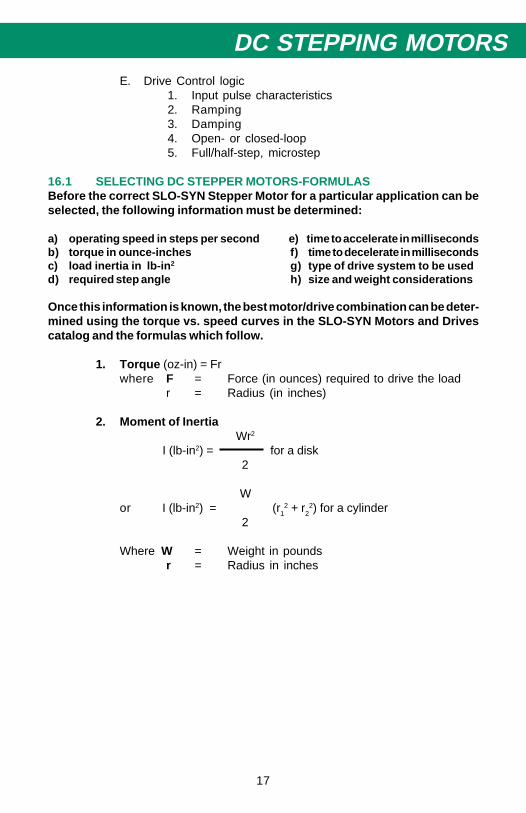
1. Torque (oz-in) = Frwhere F = Force (in ounces) required to drive the load
r = Radius (in inches)
2. Moment of InertiaWr2
I (lb-in2) = for a disk2
Wor I (lb-in2) = (r1
2 + r22) for a cylinder
2
Where W = Weight in poundsr = Radius in inches
18
3. Equivalent InertiaA motor must be able to:
a. overcome any frictional load in the systemb. start and stop all inertial loads, including that of its own rotor
The basic rotary relationship is:
T = I α /24Where T = torque in ounce-inches
I = moment of inertia in lb-in2
α = angular acceleration in radians per second2
Angular acceleration (α) is a function of the change in velocity (ω) and the timerequired for the change.
ω2 - ω1α =
t
or, if starting from zero
ωα =
t
where ω = angular velocity in radians per secondt = time in seconds
steps per secondsince ω = x 2π
steps per revolution
angluar velocity and angular acceleration can also be expressed insteps per second (ω1) and steps per second2 (α), respectively.
SAMPLE CALCULATIONS
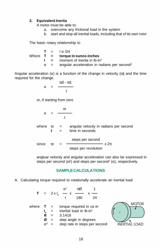
A. Calculating torque required to rotationally accelerate an inertial load
α1 πØ 1T = 2 x I0 x x
t 180 24
where T = torque required in oz-inI0 = inertial load in lb-in2
πππππ = 3.1416Ø = step angle in degreesα1 = step rate in steps per second

19
DC STEPPING MOTORS
EXAMPLE: assume the following conditions:
Inertia = 9.2 lb-in2step angle = 1.8°acceleration = from 0 to 1000 steps per second in 0.5 seconds
1000 p x 1.8 1T = 2 x 9.2 x x x
0.5 180 24
T = 48.2 oz-in torque required to
B. Calculating torque required to accelerate and raise a weight using a drum and string.
The total torque which the motor must supply includes the torque required to:a. accelerate the weightb. accelerate the drumc. accelerate the motor rotord. lift the weight
The rotational equivalent of the weight and the radius of the drum is:
I(eq) = wr2
where I(eq) = equivalent inertia in lb-in2
w = weight in lbsr = radius of drum in inches

20
EXAMPLE: Assume the following conditionsWeight 5 lbs (80 oz)Drum 3 inches O.D., 1.5 inches radiusVelocity 15 ft per secondTime To Reach Velocity 0.5 secondMotor Rotor Inertia 2.5 lb-in2
Drum Inertia (3" dia x 2" lg., steel) 4-5 lb-in2
I(eq) = 5 x (1.5)2 = 11.25 lb-in2
I (drum) = 4.50 lb-inI (rotor) = 2.50 lb-inI (total) = 18.25 lb-in2
since the velocity is 15 ft per second using a 3" drum, the velocity in rev.per second can be calculated.
15 x 12speed = = 19.1 rev per second
3 x π
The motor step angle is 1.8°, or 200 steps per revolution.
Therefore:
ω' = 19.1 x 200 = 3820 steps per second
ω' π x Ø 1T = 2 x I0 x x x
t 180 24
3820 3.1416 x 1.8 1T = 2 x 18.25 x x x
0.5 180 24
T = 364 oz-in = torque required to accelerate the system
Torque required to lift the weight equals
T = wr= 80 x 1.5= 120 oz-in
total torque required is, therefore:
364 oz-in (torque to accelerate)120 oz-in (lifting torque)484 oz-in (total torque)

21
DC STEPPING MOTORSC Calculating the torque required to accelerate a mass moving horizontally and driven by a rack and pinion or similar device.
The total torque which the motor must provide includes the torque required to:
a. accelerate the weight, including that of the rackb. accelerate the gearc. accelerate the motor rotord. overcome the frictional losses
to calculate the rotational equivalent of the weight:
I(eq) = w r2
where w = weight in lbsr = radius in inches
EXAMPLE
assume:weight = 5 lbgear pitch diameter = 3 inchesgear radius = 1.5 inchesvelocity = 15 feet per secondtime to reach velocity = 0.5 secondpinion inertia = 4.5 lb-in2motor rotor inertia = 2.5 lb-in2
I(eq) = w r2 = 5 x (1.5)2 = 11.25 lb-in2
I pinion = 4.5 lb-in2
I rotor = 2.5 lb-in2
I total = 18.25 lb-in2
Velocity is 15 feet per second with a 3" pitch diameter gear.
Therefore:
15 x 12Speed = = 19.1 rev. per second
3 x π
22
The motor step angle is 1.8° (200 steps per revolution). Therefore, the velocityin steps per second is:
w = 19.1 x 200 = 3820 steps per second
To calculate the torque needed to accelerate the system:
ω' πØ 1T = 2 x I0 x x x
t 180 24
3820 3.1416 x 1.8 1T = 2 x 18.25 x x x
0.5 180 24
T = 364 oz-in
To calculate torque needed to slide the weight, assume a frictional force of 6 oz.
T friction = 6 x 1.5 = 9 oz-in
Total torque required = 364 oz-in+ 9 oz-in
= 373 oz-in
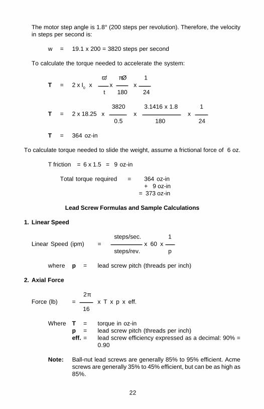
Lead Screw Formulas and Sample Calculations
1. Linear Speed
steps/sec. 1Linear Speed (ipm) = x 60 x
steps/rev. p
where p = lead screw pitch (threads per inch)
2. Axial Force
2πForce (lb) = x T x p x eff.
16
Where T = torque in oz-inp = lead screw pitch (threads per inch)eff. = lead screw efficiency expressed as a decimal: 90% =
0.90
Note: Ball-nut lead screws are generally 85% to 95% efficient. Acmescrews are generally 35% to 45% efficient, but can be as high as85%.

23
DC STEPPING MOTORSA. Calculating the torque required to accelerate a mass moving horizontally and driven by a ball bearing lead screw and nut.
The total torque the motor must provide includes the torque required to:
a. accelerate the weightb. accelerate the lead screwc. accelerate the motor rotord. overcome the frictional force
to calculate the rotational equivalent of weight w:1
I(eq) = w x x (1/2π)2
p2
where w = weightp = pitch in threads per inchI(eq) = equivalent polar inertial in lb-in2
to calculate lead screw inertia (steel screw)
I screw = D4 x length x 0.028
EXAMPLE
weight = 100 lbvelocity = 0.15 ft per secondtime to reach velocity = 0.1 secondball screw diameter = 1.5 inchesball screw length = 48 inchesball screw pitch = 5 threads per inchmotor rotor inertia = 2.5 lb-in2friction force to slide weight = 6 oz.
1I(eq) = w x x 0.025
p2
1I(eq) = 1000 x x 0.025
25
I(eq) = 1.0 lb-in2I (screw) = D4 x length x 0.028I (screw) = 5.06 x 48 x 0.028I (screw) = 6.8 lb-in2I (screw) = 6.8 lb-in2I(eq) = 1.0I rotor = 2.5 lb-in2I total = 10.3 lb-in

24
Velocity is 0.15 feet per second, which is equal to 1800 steps per second (themotor steps in 1.8° increments).
Torque to accelerate system
ω' 3.14146 x 1.8 1T = 2 x I0 x x x
t 180 24
1800 3.1416 x 1.8 1T = 2 x 10.3 x x x
0.1 180 24
T = 484 oz-in
Torque to overcome friction
F = 0.393 x T x p x eff.
6/16= 0.393 x T x 0.90
where F = frictional force in lb-inT = torque in oz-inp = lead screw pitch in threads per inchT = 0.22 oz-in
Total torque required = 0.22 oz-in484.00 oz-in484.22 oz-in
CONVERSION FACTORSINERTIAslug-ft2 x 4600 = lb-in2
lb-ft2 x 144 = lb-in2
oz-in2 x 0.0625 = lb-in2
lb-ft-sec2 x 4600 = lb-in2
lb-ft-sec2 x 384 = lb-in2
oz-in-sec2 x 24 = lb-in2
gm-cm2 x 0.000342 = lb-in2
kp-m-sec2 x 33,500 = lb-in2
METRIC - DECIMAL EQUIVALENTS1 inch = 2.54 cm1 cm = 0.3937 inch1 pond (gm) = 0.03527 oz.1 oz = 28.35 pond (gm)1 kp (kg) = 2.205 pound1 gm-cm = 0.0139 oz-in1 kg-cm = 1 kp-cm = 13.9 oz-in1 hp = 746 watts
25
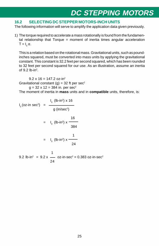
DC STEPPING MOTORS16.2 SELECTING DC STEPPER MOTORS-INCH UNITSThe following information will serve to amplify the application data given previously.
1) The torque required to accelerate a mass rotationally is found from the fundamen-tal relationship that Torque = moment of inertia times angular accelerationT = I0 α.
This is a relation based on the rotational mass. Gravitational units, such as pound-inches squared, must be converted into mass units by applying the gravitationalconstant. This constant is 32.2 feet per second squared, which has been roundedto 32 feet per second squared for our use. As an illustration, assume an inertiaof 9.2 lb-in2.
9.2 x 16 = 147.2 oz-in2
Gravitational constant (g) = 32 ft per sec2
g = 32 x 12 = 384 in. per sec2
The moment of inertia in mass units and in compatible units, therefore, is:
I0 (lb-in2) x 16I0 (oz-in sec2) =
g (in/sec2)
16= I0 (lb-in2) x
384
1= I0 (lb-in2) x
24
19.2 lb-in2 = 9.2 x oz-in-sec2 = 0.383 oz-in-sec2
24

26
2) Angular acceleration alpha (α) in the expression T - I0 α is in units of radians persecond squared, α = rad/sec2. A circle (360°) contains 2 pi radians, 360° - 2πradians, or one radian = 57.3 degrees (approximately). Acceleration is thechange of velocity per unit of time. In the rotational case being considered,velocity is expressed in radians per second and is denoted by ω (omega). Theangular velocity for a stepper motor is therefore equal to the stepping rate (stepsper second) times the step angle in radians.
2πStep angle (radians) = step angle (degrees) x
360
Assume a 200 step per revolution (1.8° per step) motor running at 1000 steps persecond.
2πw = 1000 x 1.8 x
360
= 31.42 radians per second
The angular acceleration, α is the rate of change of angular velocity per unit oftime (seconds). If the change is from zero speed, or velocity, the angularacceleration is the final angular velocity (ω2) divided by the time taken to reachthat velocity.
Assume the above motor reaches the speed of 1000 steps per second in 0.5second. The angular velocity is:
ω2
31.42α = = = 62.84 rad. per sec2
t 0.5
If the change of velocity is from a first speed (ω1) to a second speed (ω2), theacceleration is:
ω2 - ω1
α =t
To obtain the acceleration torque in oz-in, the inertia must be expressed in oz-in-sec2 and the acceleration in radians/sec2.
3) To accelerate an inertia of 9.2 lb-in2 to 1000 steps per second in 0.5 secondrequires what torque?
T = I0 (oz-in-sec2) x (rad/sec2)= 0.383 x 62.84= 24.1 oz-in
4) For 1.8° per step (200 step per revolution) motors, this may be restated as:
change in speed (steps per second) 1.8 x πT (oz-in) = I0(lb-in2) x x
time for change (seconds) 24 x 360∆s
= I0 x x 1.31 x 10-3
∆t

27
DC STEPPING MOTORS
16.3 SELECTING DC STEPPER MOTORS - METRIC UNITS1) The torque required to accelerate a mass rotationally is found from the fundamen-
tal relationship that Torque = moment of inertia times angular acceleration:T = I0 α
This is a relationship based on the rotational mass. Gravitational units, such askg-cm squared, must be converted into mass units by applying the gravitationalconstant. This constant is 981 cm/sec squared, which has been rounded off to980 cm/second squared for our use. As an example, assume an inertia of 26.9kg-cm2.
Gravitational constant is 980 cm/sec2
The moment of inertia in mass units and in compatible units, therefore, is:
I0 (kg-cm2)I0 (kg-cm-sec2) =
g (cm/sec2)
1= I (kg-cm2) x
980
126.9 kg-cm2 x = 0.027 kg-cm-sec2
980
2) Angular acceleration alpha (α) in the expression T=I0 α is in units of radians persecond squared.
A circle (360°) contains 2 pi radians: 360° = 2π radians, or one radian = 57.3degrees (approximately). Acceleration is the change of velocity per unit of time.In the rotational case being considered, velocity is expressed in radians persecond and is denoted by ω (omega). The angular velocity for a stepper motoris therefore equal to the stepping rate (in steps per second) times the step angle(in radians).
2πStep Angle (radians) = step angle (degrees) x
360Assume a 200 step per revolution (1.8° step angle) motor running at 1000 stepsper second.
2πω = 1000 x 1.8 x
360= 31.42 radians per second
The angular acceleration (a) is the change of velocity per unit of time (seconds).If the change is from zero speed or velocity, the angular acceleration is theangular velocity (ω2) divided by the time taken to reach that velocity.
Assume the above motor reaches the speed of 1000 steps per second in 0.5second. The angular velocity is: ω2 = 31.42 radians per second.
ω2 31.42α = = = 62.84 radians per second2
t 0.5

28
If the change in velocity is from first speed (ω1) to a second speed (ω2), theacceleration is:
ω2 - ω2
α = t
To obtain the acceleration torque in kg-cm, the inertia must be kb-cm-sec2.
3) What torque is required to accelerate an inertia of 26.9 kg-cm2 to 1000 steps persecond in 0.5 second?
T = I0 (kg-cm-sec2) x rad/sec2
= 0.027 x 62.84
= 1.7 kg-cm
4) For 1.8° per step (200 steps per revolution) motors, this may be restated as:
change in speed (steps/sec 1 1.8 x 2πT (kg-cm2) = I0 x x x
time for change (seconds) 980 360
∆s= I0 (kg-cm2) x x 3.2 x 10-5
∆t
1000T = 26.9 x x 3.2 x 10-5
0.5
= 1.72 kg-cm
17.0 APPLICATIONSThe applications for SLO-SYN Stepper Motors are virtually unlimited. Listed aresome typical applications where reliability, repeatability and controllability are mostimportant.
APPLICATION USE
Computer PeripheralsFloppy Disc position magnetic pickupPrinter carriage drivePrinter rotate character wheelPrinter paper feedPrinter ribbon wind/rewindPrinter position matrix print headTape Reader index tapePlotter X-Y-Z positioningPlotter paper feed

29
DC STEPPING MOTORSAPPLICATION USE
Business MachinesCard Reader position cardsCopy Machine paper feedBanking Systems credit card positioningBanking Systems paper feedTypewriters (automatic) head positioningTypewriters (automatic) paper feedCopy Machine lens positioningCard Sorter route card flow
Process ControlCarburetor Adjusting air-fuel mixture adjustValve Control fluid gas meteringConveyor main driveIn-Process Gaging parts positioningAssembly Lines parts positioningSilicon Processing I.C. wafer slicingI.C. Bonding chip positioningLaser Trimming X-Y positioningLiquid Gasket Dispensing valve cover positioningMail Handling System feeding and positioning letters
Machine ToolMilling Machines X-Y-Z table positioningDrilling Machines X-Y table positioningGrinding Machines downfeed grinding wheelGrinding Machines automatic wheel dressingElectron Beam Welder X-Y-Z positioningLaser Cutting X-Y-Z positioningLathes X-Y positioningSewing X-Y table positioning
GraphicsPrinting Presses roller drivePrinting Presses ink pumpPhototypesetting Equipment rotate character wheel and paper feedFilm Processing index film frame-by-frameAnimation Camera control focus, fade, dissolve, etc.Microfilm Systems position filmMicrofilm Systems automatic focus
MedicalI.V. Pump control drip plateX-Ray Equipment scanning head positioningX-Ray Equipment position patientBlood Analyzer test tube positioningRadiation Therapy scanning head positioning

30
18.0 THE ELECTRONIC DRIVEThe most important element in any stepper motor system is the electronic drivewhich controls the motor.
The "drive" determines the performance characteristics of a given motor. Param-eters such as speed, time for a single step, holding torque and setting time can becontrolled by the electronic drive.
18.1 L/R UNIPOLAR DRIVESThis is the simplest form of stepper motor control. It has a single-ended power supply,winding sequence logic, and series resistance between drive and motor, andprovides good performance to 2000 steps per second. Other advantages includehigh reliability and low cost.
L/R Unipolar DriveFIGURE 11
18.2 L/R BIPOLAR DRIVESThis type of drive requires two power supplies of equal current capability. Theyprovide good intermediate speed performance (2k to 5k sps). They energize allwindings simultaneously to achieve a 30% to 40% increase over unipolar L/R drivesin low speed torque. An L/R bipolar drive requires a four-lead or an eight-leadstepper motor.
18.3 TWO LEVEL DRIVESThese drives utilize two power supplies to achieve fast current rise to initiate the stepand to sustain the current during the entire move. They are well suited forapplications requiring short, fast moves and provide good intermediate speedperformance.
18.4 REACTIVE DRIVESA reactive drive uses a choke on the input of the power supply. This allows voltageto increase as the stepping rate is increased. No series resistor is required. This typeof drive provides good overall performance. It is more expensive than an L/R drive,but is more efficient.
18.5 CHOPPER DRIVESThis is a more complex drive that "chops" the current to achieve current limiting. Highvoltage that can be many times the rated voltage of the motor can be applied. Thesedrives provide good overall performance and fast response, but are expensive.
- +BLACK
WHITE
GREEN
RED/WHITE
GREEN/WHITE
REDSW1
SW2
SW3
SW4
R
R
31
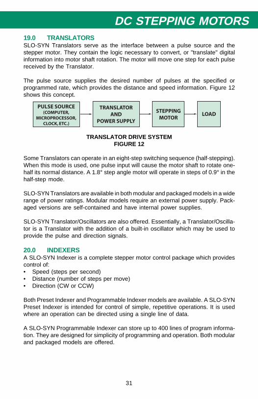
DC STEPPING MOTORS19.0 TRANSLATORSSLO-SYN Translators serve as the interface between a pulse source and thestepper motor. They contain the logic necessary to convert, or "translate" digitalinformation into motor shaft rotation. The motor will move one step for each pulsereceived by the Translator.
The pulse source supplies the desired number of pulses at the specified orprogrammed rate, which provides the distance and speed information. Figure 12shows this concept.
TRANSLATOR DRIVE SYSTEMFIGURE 12
Some Translators can operate in an eight-step switching sequence (half-stepping).When this mode is used, one pulse input will cause the motor shaft to rotate one-half its normal distance. A 1.8° step angle motor will operate in steps of 0.9° in thehalf-step mode.
SLO-SYN Translators are available in both modular and packaged models in a widerange of power ratings. Modular models require an external power supply. Pack-aged versions are self-contained and have internal power supplies.
SLO-SYN Translator/Oscillators are also offered. Essentially, a Translator/Oscilla-tor is a Translator with the addition of a built-in oscillator which may be used toprovide the pulse and direction signals.
20.0 INDEXERSA SLO-SYN Indexer is a complete stepper motor control package which providescontrol of:• Speed (steps per second)• Distance (number of steps per move)• Direction (CW or CCW)
Both Preset Indexer and Programmable Indexer models are available. A SLO-SYNPreset Indexer is intended for control of simple, repetitive operations. It is usedwhere an operation can be directed using a single line of data.
A SLO-SYN Programmable Indexer can store up to 400 lines of program informa-tion. They are designed for simplicity of programming and operation. Both modularand packaged models are offered.

32
20.0 THE DRIVE SELECTION PROCESSFollow the procedure below to select the correct motor and drive combination foryour application.
A. Select the step angle which will provide the desired linear resolution.B. Select the type of drive - Translator, Translator/Oscillator, Preset Indexer or
Programmable Indexer.C. Select the specific drive that provides the speed range required.D. Consult the literature which gives torque vs. speed curves for the selected drive
used with appropriate motors.E. Select the motor which provides the necessary step angle and torque at the
required step rate.
EXAMPLEAn X-Y table must be positioned at a rate of 255 inches per minute (4.25 inches persecond). The table is positioned by a 5-pitch ball nut lead screw. Linear resolutionof 0.001 inch per motor step is required. The required torque is 51 ounce-inches,including the torque needed to accelerate the inertia. It is desired to have the motordrive the table a pre-selected distance each time a "Start" command is given.
SolutionA. Select the required motor step angle needed to achieve the correct linear
resolution. In this case, a 1.8°, 200 step per revolution stepper will provide thedesired 0.001 inch linear motion per motor step when operating a 5-pitch (fiverevolutions = 1 inch linear motion) lead screw.
B. Counting capability with the ability to store a single line of program informationis needed. Therefore, a Preset Indexer should be selected.
C. The required speed is 4250 steps per second (5-pitch lead screw, 1000 steps= 1" linear motion; 4.25 inches/sec required = 4250 steps per second).
D. Consult the torque vs. speed curves in the SLO-SYN Motion Control catalog andselect a Motor/Indexer combination that drive the load at the required step rate.

33
DC STEPPING MOTORS
DISTRIBUTION COAST-TO-COASTAND INTERNATIONAL
Superior Electric SLO-SYN products are available nationwide through anextensive authorized distributor network. These distributors offer literature,technical assistance and a wide range of models off the shelf for fastestpossible delivery and service.
In addition, Superior Electric sales engineers and manufacturers' representa-tives are conveniently located to provide prompt attention to customers'needs. Call Superior Electric customer service for ordering and applicationinformation or for the address of the closest authorized distributor for SuperiorElectric's SLO-SYN products.
IN U.S.A. and CANADA383 Middle StreetBristol, CT 06010Tel: (860) 585-4500FAX: 860-589-2136Customer Service: 1-800-787-3532Product Application: 1-800-787-3532FAX: 1-800-766-6366Product Literature Request: 1-800-787-3532Web Site: www.superiorelectric.com
IN EUROPEWarner Electric (Int.) Inc.La PierreireCH-1029 Villars-Ste-Croix, SwitzerlandTel: 41 21 631 33 55Fax: 41 21 636 07 04