Embed Size (px)
Citation preview
AC MotorSpeedControl
Models 13E632 thru 13E643
A40352
Operating Instructions & Parts Manual EN

PLEASE READ AND SAVE
THESE INSTRUCTIONS.
READ CAREFULLY
BEFORE ATTEMPTING
TO ASSEMBLE, INSTALL,
OPERATE OR MAINTAIN THE
PRODUCT DESCRIBED.
PROTECT YOURSELF AND
OTHERS BY OBSERVING ALL
SAFETY INFORMATION. FAILURE
TO COMPLY WITH INSTRUCTIONS
COULD RESULT IN PERSONAL
INJURY AND/OR PROPERTY
DAMAGE! RETAIN INSTRUCTIONS
FOR FUTURE REFERENCE.
PLEASE REFER TO BACK COVER
FOR INFORMATION REGARDING
DAYTON’S WARRANTY AND OTHER
IMPORTANT INFORMATION.
Model #: ___________________
Serial #: ___________________
Purch. Date: _______________
Form 5SXXXX / Printed in XXXX
XXXXX Version XX XX/XXXX
© 2013 Dayton Electric Manufacturing Co.
All Rights Reserved
Form 5S7462 / Printed in USA 08963 Version B 08/2014
© 2014 Dayton Electric Manufacturing Co.All Rights Reserved
©2014 Dayton Electric Mfg. Co.
AC MOTOR SPEED CONTROLAC MOTOR SPEED CONTROL
NEMA 4X / IP 65
Hybrid Drive™
Assembled in U.S.A.
Mfd. for Dayton Electric Mfg. Co.,
Lake Forest, IL 60045-5201 U.S.A.
For Repair Parts Call 1-800-323-0620
NEMA 4X / IP 65
Hybrid Drive™
Assembled in U.S.A.
Mfd. for Dayton Electric Mfg. Co.,
Lake Forest, IL 60045-5201 U.S.A.
For Repair Parts Call 1-800-323-0620
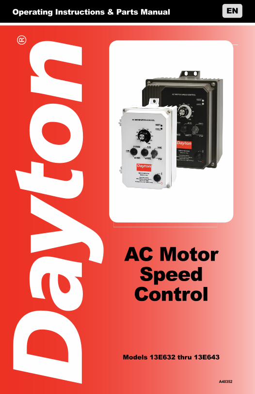
Installation & Operation Manual
Models 13E632 – 13E643Adjustable Frequency Drives for 3-Phase AC Motors
NEMA 4X / IP 65
Variable Speed/Soft-Start AC Motor Drive with Electronic Motor Overload Protection1
Washdown and Watertight for Indoor and Outdoor Use Rated for 208 – 230 and 400/460 Volt 50 & 60 Hz
3-Phase & PSC2 AC Induction Motors from Subfractional thru 5HP
Operates from 115, 208/230 Volt and 400/460 Volt 50/60 Hz AC Line2,3
Notes: 1. UL approved as an electronic overload protector for motors. 2. Special software is available – contact our Sales Department. 3. Do not use this drive with GFCIs. 4. Installation of a CE approved RFI filter is required.
The information contained in this manual is intended to be accurate. However, the manufacturer retains the right to make changes in design which may not be included herein.
NOTE: THE DRIVE IS FACTORY SET FOR 60 HZ MOTORS. FOR 50 HZ MOTORS, SEE SECTION 6.4 ON PAGE 18.
See Safety Warning on Page 5.
4
ii
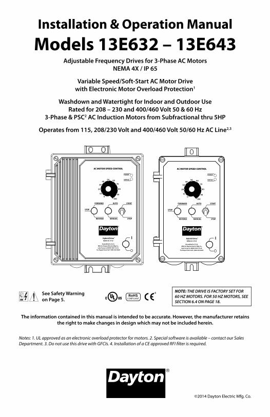
Table of ContentsSection Page1 Quick-Start Instructions . . . . . . . . . . . . . . . . . . . . . . . . . . . . . . . . . . . . . . . . . . . . . . . . . . . . . 4 2 Safety Warning . . . . . . . . . . . . . . . . . . . . . . . . . . . . . . . . . . . . . . . . . . . . . . . . . . . . . . . . . . . 53 Introduction . . . . . . . . . . . . . . . . . . . . . . . . . . . . . . . . . . . . . . . . . . . . . . . . . . . . . . . . . . . . 64 Important Application Information . . . . . . . . . . . . . . . . . . . . . . . . . . . . . . . . . . . . . . . . . . . . . 135 Wiring Instructions . . . . . . . . . . . . . . . . . . . . . . . . . . . . . . . . . . . . . . . . . . . . . . . . . . . . . . . 146 Setting Selectable Jumpers . . . . . . . . . . . . . . . . . . . . . . . . . . . . . . . . . . . . . . . . . . . . . . . . . . 187 Mounting Instructions . . . . . . . . . . . . . . . . . . . . . . . . . . . . . . . . . . . . . . . . . . . . . . . . . . . . . 208 Recommended High Voltage Dielectric Withstand Testing (Hi-Pot Testing) . . . . . . . . . . . . . . . . . . . . 229 Reconditioning the Bus Capacitors . . . . . . . . . . . . . . . . . . . . . . . . . . . . . . . . . . . . . . . . . . . . . 2210 Drive Operation . . . . . . . . . . . . . . . . . . . . . . . . . . . . . . . . . . . . . . . . . . . . . . . . . . . . . . . . . 2211 AC Line Fusing . . . . . . . . . . . . . . . . . . . . . . . . . . . . . . . . . . . . . . . . . . . . . . . . . . . . . . . . . . 2212 Diagnostic LEDs . . . . . . . . . . . . . . . . . . . . . . . . . . . . . . . . . . . . . . . . . . . . . . . . . . . . . . . . . 2313 Trimpot Adjustments . . . . . . . . . . . . . . . . . . . . . . . . . . . . . . . . . . . . . . . . . . . . . . . . . . . . . . 23Appendix A – Optional Signal Isolator with Power Supply (Model No. 13E666) . . . . . . . . . . . . . . . . . . . 27Limited Warranty. . . . . . . . . . . . . . . . . . . . . . . . . . . . . . . . . . . . . . . . . . . . . . . . . . . . . . . . . . . 28
Tables Page1 Jumper Selectable Features. . . . . . . . . . . . . . . . . . . . . . . . . . . . . . . . . . . . . . . . . . . . . . . . . . . 82 Optional Accessories . . . . . . . . . . . . . . . . . . . . . . . . . . . . . . . . . . . . . . . . . . . . . . . . . . . . . . . 83 General Performance Specifications . . . . . . . . . . . . . . . . . . . . . . . . . . . . . . . . . . . . . . . . . . . . 104 Electrical Ratings. . . . . . . . . . . . . . . . . . . . . . . . . . . . . . . . . . . . . . . . . . . . . . . . . . . . . . . . . 105 Terminal Block Wiring Information . . . . . . . . . . . . . . . . . . . . . . . . . . . . . . . . . . . . . . . . . . . . . 146 Drive Operating Condition and Run/Fault Relay Contact Status . . . . . . . . . . . . . . . . . . . . . . . . . . . 177 Drive Operating Condition and Status LED Indicator . . . . . . . . . . . . . . . . . . . . . . . . . . . . . . . . . . 23
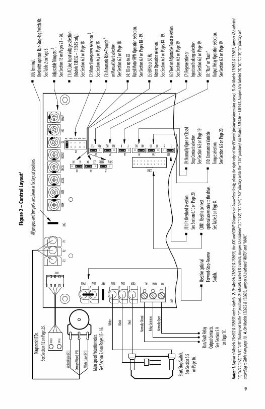
Figures Page1 Quick-Start Connection Diagram . . . . . . . . . . . . . . . . . . . . . . . . . . . . . . . . . . . . . . . . . . . . . . . 42 Control Layout . . . . . . . . . . . . . . . . . . . . . . . . . . . . . . . . . . . . . . . . . . . . . . . . . . . . . . . . . . . 93 Models 13E632 & 13E633 Mechanical Specifications . . . . . . . . . . . . . . . . . . . . . . . . . . . . . . . . . . 114 Models 13E634 – 13E643 Mechanical Specifications . . . . . . . . . . . . . . . . . . . . . . . . . . . . . . . . . . 125 Maximum Allowed Motor Torque vs. Speed. . . . . . . . . . . . . . . . . . . . . . . . . . . . . . . . . . . . . . . . 136 Open Ventilated Motor with External Fan Cooling. . . . . . . . . . . . . . . . . . . . . . . . . . . . . . . . . . . . 137 Models 13E632 – 13E637, AC Line Input, Motor, and Ground Connections . . . . . . . . . . . . . . . . . . . . 148 Models 13E638 – 13E643 AC Line Input, Motor, and Ground Connections . . . . . . . . . . . . . . . . . . . . 159 Remote Main Speed Potentiometer Connection. . . . . . . . . . . . . . . . . . . . . . . . . . . . . . . . . . . . . 1510 Remote Start/Stop Switch Connection with Normally Open Stop Contact . . . . . . . . . . . . . . . . . . . . 1511 Remote Start/Stop Switch Connection with Normally Closed Stop Contact . . . . . . . . . . . . . . . . . . . 1612 Start/Stop Function Eliminated . . . . . . . . . . . . . . . . . . . . . . . . . . . . . . . . . . . . . . . . . . . . . . . 1613 Voltage Following Connections . . . . . . . . . . . . . . . . . . . . . . . . . . . . . . . . . . . . . . . . . . . . . . . 1614 Enable Circuit Connection. . . . . . . . . . . . . . . . . . . . . . . . . . . . . . . . . . . . . . . . . . . . . . . . . . . 1715 Run/Fault Relay Output Contacts Connection . . . . . . . . . . . . . . . . . . . . . . . . . . . . . . . . . . . . . . 1716 Models 13E632 – 13E635 AC Line Input Voltage Selection (Jumper J1) . . . . . . . . . . . . . . . . . . . . . . 1817 Removing Jumper J1 on Models 13E632 – 13E635 . . . . . . . . . . . . . . . . . . . . . . . . . . . . . . . . . . . 1818 Motor Horsepower Selection (Jumper J2) . . . . . . . . . . . . . . . . . . . . . . . . . . . . . . . . . . . . . . . . . 1819 Automatic Ride-Through or Manual Restart Selection (Jumper J3) . . . . . . . . . . . . . . . . . . . . . . . . . 1920 60 Hz and 50 Hz Motor Selection (Jumpers J4 and J5) . . . . . . . . . . . . . . . . . . . . . . . . . . . . . . . . . 1921 Available Torque vs. Output Frequency . . . . . . . . . . . . . . . . . . . . . . . . . . . . . . . . . . . . . . . . . . 1922 120 Hz and 100 Hz Drive Output Frequency Selection . . . . . . . . . . . . . . . . . . . . . . . . . . . . . . . . . 1923 Fixed or Adjustable Boost Selection (Jumper J6). . . . . . . . . . . . . . . . . . . . . . . . . . . . . . . . . . . . . 20
iii
24 Regenerative or DC Injection Braking Selection (Jumper J7) . . . . . . . . . . . . . . . . . . . . . . . . . . . . . 2025 “Run” or “Fault” Output Relay Operation Selection (Jumper J8). . . . . . . . . . . . . . . . . . . . . . . . . . . . 2026 Normally Open or Closed Stop Contact Selection (Jumper J9) . . . . . . . . . . . . . . . . . . . . . . . . . . . . 2027 Constant or Variable Torque Selection (Jumper J10) . . . . . . . . . . . . . . . . . . . . . . . . . . . . . . . . . . 2028 I2t Overload Selection (Jumper J11) . . . . . . . . . . . . . . . . . . . . . . . . . . . . . . . . . . . . . . . . . . . . . 2029 Typical Hi-Pot Test Setup. . . . . . . . . . . . . . . . . . . . . . . . . . . . . . . . . . . . . . . . . . . . . . . . . . . . 2130 Minimum Speed Trimpot (MIN) Range . . . . . . . . . . . . . . . . . . . . . . . . . . . . . . . . . . . . . . . . . . . 2331 Maximum Speed Trimpot (MAX) Range . . . . . . . . . . . . . . . . . . . . . . . . . . . . . . . . . . . . . . . . . . 2332 Acceleration Trimpot (ACCEL) Range . . . . . . . . . . . . . . . . . . . . . . . . . . . . . . . . . . . . . . . . . . . . 2333 Deceleration Trimpot (DECEL) Range . . . . . . . . . . . . . . . . . . . . . . . . . . . . . . . . . . . . . . . . . . . . 2434 DC Injection Brake Trimpot (DECEL) Range . . . . . . . . . . . . . . . . . . . . . . . . . . . . . . . . . . . . . . . . 2435 Slip Compensation Trimpot (COMP) Range . . . . . . . . . . . . . . . . . . . . . . . . . . . . . . . . . . . . . . . . 2436 Current Limit Trimpot (CL) Range . . . . . . . . . . . . . . . . . . . . . . . . . . . . . . . . . . . . . . . . . . . . . . 2437 I2t Trip Time vs. Motor Current . . . . . . . . . . . . . . . . . . . . . . . . . . . . . . . . . . . . . . . . . . . . . . . . 2538 Boost Trimpot (BOOST) Range . . . . . . . . . . . . . . . . . . . . . . . . . . . . . . . . . . . . . . . . . . . . . . . . 2639 Jog Trimpot (JOG) Range . . . . . . . . . . . . . . . . . . . . . . . . . . . . . . . . . . . . . . . . . . . . . . . . . . . 26
Items Included In this Package:Adjustable Frequency Drive, Installation and Operation Manual, Trimpot Adjustment Tool, CE Approved Product Information Card, and Warranty Registration Card.
230 VAC ControlsSuitable For Use on a Circuit Capable of Delivering Not More Than 5 kA RMS Symmetrical Amperes, 230 Volts Maximum.Use Copper Conductors Rated 75 ºC.Suitable for Operation in a Maximum Surrounding Air Temperature of 40 ºC.
460 VAC ControlsSuitable For Use on a Circuit Capable of Delivering Not More Than 5 kA RMS Symmetrical Amperes, 460 Volts Maximum.Use Copper Conductors Rated 75 ºC.Suitable for Operation in a Maximum Surrounding Air Temperature of 40 ºC.
UL Notice
4
1 QUICK-START INSTRUCTIONS
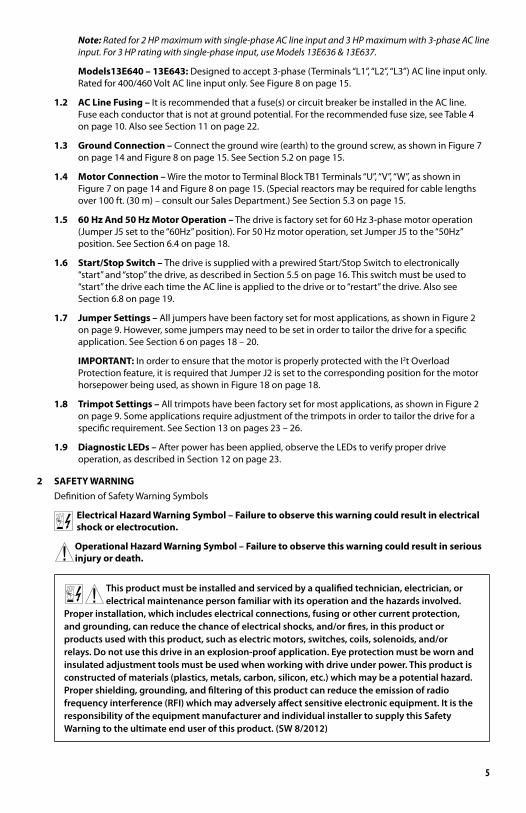
Important – You must read these simplified instructions before proceeding. These instructions are to be used as a reference only and are not intended to replace the details provided herein. You must read the Safety Warning on page 5 before proceeding.
Reconditioning the Bus Capacitors – If this drive has been in storage for over one year, it is necessary to recondition the power supply bus capacitors. To recondition the bus capacitors, apply the AC Line with the drive in the Stop Mode for a minimum of one hour. Not following this procedure will cause the bus capacitors to fail.
See Figure 1. Also see Section 4 - Important Application Information on Page 13.
WARNING! Disconnect main power before making connections to the drive.
1.1 AC Line Input Connection – Wire the AC line input to Terminal Block TB1. See Section 5.1 on pages 14 – 15.
Application Note: Do not wire this drive to a GFCI. If operation with a GFCI is required, contact our Sales Department.
Note: The rated AC line voltage of the drive must match the actual AC line input voltage. On Models 13E632 – 13E635, the setting of Jumper J1 must match the AC line input voltage.
Models 13E632 – 13E637: Designed to accept single-phase (Terminals “L1”, “L2”) AC line input only. Rated for 208/230 Volt AC line input with Jumper J1 set to the “230V” position (factory setting). Rated for 115 Volt AC line input with Jumper J1 set to the “115V” position. See Figure 7 on page 14.
Note: Models 13E634 & 13E635 are rated for 11⁄2 HP maximum with 115 Volt AC line input and 2 HP maximum with 208/230 Volt AC line input.
Models 13E638 & 13E639: Designed to accept single-phase (Terminals “L1”, “L2”) or 3-phase (Termi-nals “L1”, “L2”, “L3”) AC line input. Rated for 208/230 Volt AC line input only. See Figure 8 on page 15.
see Section 5.2 on page 15.Ground (Earth):
(Terminals L1, L2, L3)
see Section 5.1 on pages 14 – 15.Models 13E638 – 13E643:
50/60 Hz, AC Line Input208/230, 400/460 Volt, 3-Phase,
(Terminals L1, L2)
see Section 5.1 on pages 14 – 15.Models 13E632 – 13E639:
50/60 Hz, AC Line Input208/230 Volt, Single Phase,
3-Phase
see Section 5.3 on page 15.AC Induction Motor:
AC LINEM OTOR
Motor
TB1
L2L1V WU L3
Figure 1 – Quick-Start Connection Diagram*
*Layouts of Models 13E632, 13E633, 13E636 and 13E637 Vary slightly.
5
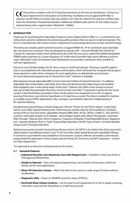
Note: Rated for 2 HP maximum with single-phase AC line input and 3 HP maximum with 3-phase AC line input. For 3 HP rating with single-phase input, use Models 13E636 & 13E637.
Models13E640 – 13E643: Designed to accept 3-phase (Terminals “L1”, “L2”, “L3”) AC line input only. Rated for 400/460 Volt AC line input only. See Figure 8 on page 15.
1.2 AC Line Fusing – It is recommended that a fuse(s) or circuit breaker be installed in the AC line. Fuse each conductor that is not at ground potential. For the recommended fuse size, see Table 4 on page 10. Also see Section 11 on page 22.
1.3 Ground Connection – Connect the ground wire (earth) to the ground screw, as shown in Figure 7 on page 14 and Figure 8 on page 15. See Section 5.2 on page 15.
1.4 Motor Connection – Wire the motor to Terminal Block TB1 Terminals “U”, “V”, “W”, as shown in Figure 7 on page 14 and Figure 8 on page 15. (Special reactors may be required for cable lengths over 100 ft. (30 m) – consult our Sales Department.) See Section 5.3 on page 15.
1.5 60 Hz And 50 Hz Motor Operation – The drive is factory set for 60 Hz 3-phase motor operation (Jumper J5 set to the “60Hz” position). For 50 Hz motor operation, set Jumper J5 to the “50Hz” position. See Section 6.4 on page 18.
1.6 Start/Stop Switch – The drive is supplied with a prewired Start/Stop Switch to electronically “start” and “stop” the drive, as described in Section 5.5 on page 16. This switch must be used to “start” the drive each time the AC line is applied to the drive or to “restart” the drive. Also see Section 6.8 on page 19.
1.7 Jumper Settings – All jumpers have been factory set for most applications, as shown in Figure 2 on page 9. However, some jumpers may need to be set in order to tailor the drive for a specific application. See Section 6 on pages 18 – 20.
IMPORTANT: In order to ensure that the motor is properly protected with the I2t Overload Protection feature, it is required that Jumper J2 is set to the corresponding position for the motor horsepower being used, as shown in Figure 18 on page 18.
1.8 Trimpot Settings – All trimpots have been factory set for most applications, as shown in Figure 2 on page 9. Some applications require adjustment of the trimpots in order to tailor the drive for a specific requirement. See Section 13 on pages 23 – 26.
1.9 Diagnostic LEDs – After power has been applied, observe the LEDs to verify proper drive operation, as described in Section 12 on page 23.
2 SAFETY WARNING Definition of Safety Warning Symbols
Electrical Hazard Warning Symbol – Failure to observe this warning could result in electrical shock or electrocution.
Operational Hazard Warning Symbol – Failure to observe this warning could result in serious injury or death.
This product must be installed and serviced by a qualified technician, electrician, orelectrical maintenance person familiar with its operation and the hazards involved.
Proper installation, which includes electrical connections, fusing or other current protection, and grounding, can reduce the chance of electrical shocks, and/or fires, in this product or products used with this product, such as electric motors, switches, coils, solenoids, and/or relays. Do not use this drive in an explosion-proof application. Eye protection must be worn and insulated adjustment tools must be used when working with drive under power. This product is constructed of materials (plastics, metals, carbon, silicon, etc.) which may be a potential hazard. Proper shielding, grounding, and filtering of this product can reduce the emission of radio frequency interference (RFI) which may adversely affect sensitive electronic equipment. It is the responsibility of the equipment manufacturer and individual installer to supply this Safety Warning to the ultimate end user of this product. (SW 8/2012)
6
This product complies with all CE directives pertinent at the time of manufacture. Contact ourSales Department for Declaration of Conformity. Installation of a CE approved RFI filter is
required. See RFI Filters & Chokes Selection Guide D-321 (Part No. A42027) for selection of filters that meet the Industrial or Residential Standard. Additional shielded cable and/or AC line cables may be required along with a signal isolator (Model No. 13E666).
3 INTRODUCTION Thank you for purchasing this Adjustable Frequency Drive. Dayton Electric Mfg. Co., is committed to pro-
viding total customer satisfaction by producing quality products that are easy to install and operate. This drive is manufactured with surface mount components incorporating advanced circuitry and technology.
The drives are variable speed controls housed in a rugged NEMA-4X / IP-65 washdown and watertight die-cast aluminum enclosure. They are designed to operate 208 – 230 and 400/460 Volt 50 & 60 Hz 3-phase AC induction motors from subfractional thru 5HP. The sine wave coded Pulse Width Modulated (PWM) output operates at a carrier frequency of 16 kHz which provides high motor efficiency and low noise. Adjustable Linear Acceleration and Deceleration are provided, making the drive suitable for soft-start applications.
Due to its user-friendly design, this AC drive is easy to install and operate. Tailoring to specific applica-tions is accomplished with selectable jumpers and trimpots, which eliminate the computer-like program-ming required on other drives. However, for most applications no adjustments are necessary. For more advanced programming, PC based Drive-Link™ software is available.
Main features include adjustable RMS Current Limit and I2t Motor Overload Protection.* In addition, Adjustable Slip Compensation with Static Auto-Tune and Boost provides high torque and excellent load regulation over a wide speed range. Power Start™ delivers over 200% motor torque to ensure start-up of high frictional loads. Electronic Inrush Current Limit (EICL™) eliminates harmful AC line inrush current. A Run/Fault Relay is provided, which can be used to turn equipment on or off , to signal a warning if the drive is put into the Stop Mode, or if a fault has occurred. The drive is suitable for machine or variable torque (HVAC) applications. Also, a jumper is provided for selection of Regenerative or DC Injection Braking.
Standard front panel features include Diagnostic LEDs for “Power On” and “Drive Status”, a Start/Stop Switch, and a Main Speed Potentiometer. Other features include a Barrier Terminal Block to facilitate wiring of the AC line and motor, adjustable trimpots (MIN, MAX, ACCEL, DECEL, COMP, CL, JOG, BOOST), customer selectable jumpers (Line Voltage - dual voltage models only), Motor Horsepower, Automatic Ride-Through / Manual Start, Motor Frequency, Frequency Multiplier, Fixed/Adjustable Boost, Regenera-tive / Injection Braking, “Run” or “Fault” Output Relay Operation, NO/NC Stop Contact, Constant/Variable Torque and I2t Overload Selection).
Optional accessories include: Forward-Stop-Reverse Switch, On/Off AC Line Switch, Run-Stop-Jog Switch, Signal Isolator, Auto/Manual Switch, Class ”A” AC Line Filter, Multi-Speed Board and Liquidtight Fittings. A connector is provided for easy installation of accessories. Custom software: all models can be factory programmed for applications which require special timing, PLC functions, and GFCI operation – contact our Sales Department.
*UL approved as an electronic overload protector for motors.
3.1 Standard Features• IndustrialDutyDie-CastAluminumCasewithHingedCover– Available in Dark Gray finish or
FDA approved White finish.
• SimpletoOperate– Does not require programming. Uses trimpots and jumpers, which are factory set for most applications.
• MotorHPSelectionJumper– Allows the drive to be used on a wide range of motors without recalibration.
• DiagnosticLEDs– Power on (POWER) and drive status (STATUS).
• Run/FaultRelayOutputContacts– Can be used to turn equipment on or off, to signal a warning if the drive is put into the Stop Mode, or a fault has occurred.
7
• Start/StopSwitch– Provides electronic start and stop functions.
• BarrierTerminalBlock– Facilitates wiring of motor, AC line, and Run/Fault Relay Output Contacts.
• JumperSelectionofDriveOutputFrequency– Increases the motor speed up to two times the rated RPM.
• Ride-Through– Provides smooth recovery to the previous set speed during a momentary power loss (of less than 2 seconds).
• HoldingTorqueatZeroSpeed– Resists motor shaft rotation when the drive is in Stop Mode.
Note: GFCI Operation – This drive can operate with GFCIs (optional software required) – contact our Sales Department.
3.2 Performance Features• PowerStart™– Provides more than 200% starting torque which ensures startup of high frictional loads.
• SlipCompensationwithStaticAuto-TuneandBoost– Provides excellent load regulation over a wide speed range.
• SpeedRange– 60:1
3.3 PROTECTION FEATURES• MotorOverload(I2t) with RMS Current Limit* – Provides motor overload protection which
prevents motor burnout and eliminates nuisance trips.*
• ElectronicInrushCurrentLimit(EICL™)– Eliminates harmful Inrush AC line current during startup.
• ShortCircuit– Shuts down the drive if a short circuit occurs at the motor (phase-to-phase).
• Regeneration– Eliminates tripping due to high bus voltage caused by rapid deceleration of high inertial loads.
• UndervoltageandOvervoltage– Shuts down the drive if the AC line input voltage goes above or below the operating range.
• MOVInputTransientSuppression– Protects the drive components against damaging voltage spikes on the AC line.
• MicrocontrollerSelfMonitoringandAutoReboot.
*UL approved as an electronic overload protector for motors.
3.4 TRIMPOT ADJUSTMENTS• MinimumSpeed(MIN)– Sets the minimum speed of the motor. See Section 13.1 on page 24.
• MaximumSpeed(MAX)– Sets the maximum speed of the motor. See Section 13.2 on page 24.
• Acceleration(ACCEL)– Sets the amount of time for the motor to accelerate from zero speed to full speed. See Section 13.3 on page 24.
• Deceleration(DECEL)– Sets the amount of time for the motor to decelerate from full speed to zero speed. See Section 13.4 on page 24.
• DCInjectionBrake(DECEL)– When the drive is set for DC Injection Braking (Jumper J7 set to the “INJ” position), the DECEL trimpot is used to set the DC Injection Brake voltage and time. See Section 13.5 on page 24.
• SlipCompensation(COMP)– Maintains set motor speed under varying loads. See Section 13.6 on pages 24 - 25.
• CurrentLimit(CL)– Sets the current limit (overload) which limits the maximum current to the motor. See Section 13.7 on page 25.
• Boost(BOOST)– Sets the amount of Boost which can be used to obtain maximum low speed performance. See Section 13.8 on page 26.
• Jog(JOG)– Sets the “jog” speed of the motor.
8
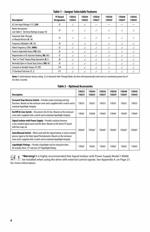
Table 1 – Jumper Selectable Features
Description1PC Board
Designation13E632 13E633
13E634 13E635
13E636 13E637
13E638 13E639
13E640 13E641
13E642 13E643
AC Line Input Voltage (115, 230) J1 p p — — — —
Motor Horsepower (see Table 4 - Electrical Ratings on page 10)
J2 p p p p p p
Automatic Ride-Through or Manual Restart (A2, M)
J3 p p p p p p
Frequency Multiplier (1X, 2X) J4 p p p p p p
Motor Frequency (50Hz, 60Hz) J5 p p p p p p
Fixed or Adjustable Boost (FIX, ADJ) J6 p p p p p p
Regenerative or DC Injection Braking (RG, INJ) J7 p p p p p p
“Run” or “Fault” Output Relay Operation (R, F) J8 p p p p p p
Normally Open or Closed Stop Contact (NO, NC) J9 p p p p p p
Constant or Variable Torque (VT, CT) J10 p p p p p p
I2t Overload Selection (1, 2) J11 p p p p p p
Notes: 1. Bold indicates factory setting. 2. In Automatic Ride-Through Mode, the drive will automatically restart due to a momentary power loss of less than 2 seconds.
Table 2 – Optional Accessories
Description13E632 13E633
13E634 13E635
13E636 13E637
13E638 13E639
13E640 13E641
13E642 13E643
Forward-Stop-Reverse Switch – Provides motor reversing and stop functions. Mounts on the enclosure cover and is supplied with a switch seal to maintain liquidtight integrity.
13E633 13E633 13E633 13E633 13E633 13E633
On/Off AC Line Switch – Disconnects the AC line. Mounts on the enclosure cover and is supplied with a switch seal to maintain liquidtight integrity.
13E667 13E668 13E669 13E669 13E669 13E669
Signal Isolator with Power Supply – Provides isolation between a non-isolated signal source and the drive. Mounts on the drive’s PC board with four snap-ins.
13E666* 13E666* 13E666* 13E666* 13E666* 13E666*Auto/Manual Switch – When used with the Signal Isolator, it selects remote process signal or the Main Speed Potentiometer. Mounts on the enclosure cover and is supplied with a switch seal to maintain liquidtight integrity.
Liquidtight Fittings – Provide a liquidtight seal for wiring the drive. Kit includes three 1/2” and one 3/4” liquidtight fittings
13E665 13E665 13E665 13E665 13E665 13E665
*Warning! It is highly recommended that Signal Isolator with Power Supply Model 13E666 be installed when using the drive with external control signals. See Appendix A, on Page 27,
for more information.
9
Outpu
t Conta
cts.
Run/F
ault R
elay
Start/
Stop S
witch.
Main S
peed P
otenti
omete
r.
Diagn
ostic L
EDs.
J4: 1X
or up
to 2X
J9: No
rmally
Open
or Clos
edJ11
: I2 t Over
load s
electio
n.
CON1
: Used
to con
nect
option
al acce
ssorie
s to th
e drive
.
Stop C
ontact
selec
tion.
Torqu
e sele
ction.
J10: Co
nstant
or Var
iable
J7: Re
genera
tive or
Outpu
t Rela
y Oper
ation
select
ion.
Inject
ion Br
aking
selec
tion.
J8: "R
un" o
r "Faul
t"
J6: Fix
ed or A
djusta
ble Bo
ost se
lectio
n.
Rated
Motor
RPM O
perati
on sel
ection
.
Motor
Opera
tion s
electio
n.J5:
60 Hz
or 50
Hz
All jum
pers a
nd trim
pots a
re show
n in fac
tory se
t positi
ons.
J1: AC
Line In
put Vo
ltage
select
ion
J2: Mo
tor Ho
rsepow
er sele
ction3 .
(Mode
ls 13E6
32 – 1
3E635
only).
J3: Au
tomati
c Ride
-Throu
gh4
or Manu
al Star
t selec
tion.
Used w
ith op
tional
Run-S
top-Jo
g Swit
ch Kit
.
Adjus
table T
rimpot
s2 .
JOG Ter
minal
.
See Se
ction 6
.6 on P
age 19
.
See Se
ction 6
.7 on P
age 19
.
See Se
ction 6
.4 on P
ages 1
8 - 19
.
See Se
ction 6
.4 on P
ages 1
8 - 19
.
See Se
ction 6
.5 on P
age 19
.
See Se
ction 6
.1 on P
age 18
.
See Se
ction 6
.2 on P
age 18
.
See Se
ction 6
.3 on P
age 18
.
See Se
ction 1
3 on P
ages 2
3 – 26
.
See Tab
le 2 on
Page
8.
See Se
ction 5
.5
See Se
ction 5
.9on
Page 1
7.
on Pag
e 16.
Norm
ally Clo
sed
Red
Norm
ally Op
en
Relay
Commo
n
See Se
ction 5
.4 on P
ages 1
5 - 16
. Black
White
See Se
ction 6
.10 on
Page
20.
See Tab
le 2 on
Page
8.
Used fo
r optio
nalFor
ward-
Stop-R
everse
Switch
.
See Se
ction 6
.8 on P
age 19
.
See Se
ction 6
.9 on P
age 20
.
White
(Low)
(P1)
Violet
(High
) (P3)
Orang
e (Wi
per) (P
2)
See Se
ction 1
2 on P
age 23
.
STATU
S
POWE
R
STOP NC NOCOMFWD COMRUNREVCOM
CON2
JOGP1
P3P2
ACCEL
MIN
MAX
JOGCL
DECEL
BOOS
T
TB2
M A
J3
2X
J4
50Hz
J5
60Hz1X
J8 J9
NC NOF
J11J10
CT 2 1VT
CON1
FIX
J6
RG RINJ
J7
ADJ
A
J2
EC DB
COMP
Figu
re 2
– Co
ntro
l Lay
out1
Note
s: 1.
Layo
ut of
Mod
els 13
e632
& 13
E633
varie
s slig
htly.
2. O
n Mod
els 13
E632
& 13
E633
, the J
OG an
d COM
P Trim
pots
are l
ocat
ed ve
rtica
lly, a
long t
he rig
ht ed
ge of
the P
C boa
rd (b
elow
the m
ount
ing sc
rew).
3. On
Mod
els 13
E632
& 13
E633
, Jump
er J2
is la
beled
“1
”, “3/
4”, “1
/2”, “
1/4”,
“1/8
” (fa
ctory
set t
o the
“1” p
ositio
n). O
n Mod
els 13
E634
& 13
E635
, Jump
er J2
is la
beled
“2”, “
11⁄2”
, “1”,
“3/4
”, “1/
2” (f
actor
y set
to th
e “11
⁄2” po
sition
). On M
odels
13E6
36 –
13E6
43, Ju
mper
J2 is
labe
led “A
”, “B”,
“C”, “
D”, “
E” (f
actor
y set
acco
rding
to Ta
ble 4
on pa
ge 10
. 4. O
n Mod
els 13
E632
& 13
E633
, Jump
er J3
is la
beled
“AUT
O” an
d “MA
N”.
10
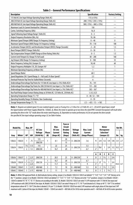
Table 3 – General Performance SpecificationsDescription Specification Factory Setting115 Volt AC Line Input Voltage Operating Range (Volts AC) 115 (±15%) —208/230 Volt AC Line Input Voltage Operating Range (Volts AC) 208 (-15%) / 230 (+15%) —400/460 Volt AC Line Input Voltage Operating Range (Volts AC) 380 (-15%) – 460 (+15%) —Maximum Load (% Current Overload for 2 Minutes) 150 —Carrier, Switching Frequency (kHz) 16, 8 —Signal Following Input Voltage Range1 (Volts DC) 0 – 5 —Output Frequency Resolution (Bits, Hz) 10, .06 —Minimum Speed Trimpot (MIN) Range (% Frequency Setting) 0 – 40 0Maximum Speed Trimpot (MAX) Range (% Frequency Setting) 70 – 110 100Acceleration Trimpot (ACCEL) and Deceleration Trimpot (DECEL) Range (Seconds) .3 – 20 1.5Boost Trimpot (BOOST) Range (Volts/Hz) 0 – 30 5Slip Compensation Trimpot (COMP) Range at Drive Rating (Volts/Hz) 0 – 3 1.5Current Limit Trimpot (CL) Range (% Full Load) 40 – 200 160Jog Trimpot (JOG) Range (% Frequency Setting) 0 – 100 35Motor Frequency Setting (Hz) (Jumper J5) 50, 60 60Output Frequency Multiplier (1X, 2X) (Jumper J4)2 1, 2 1Minimum Operating Frequency at Motor (Hz) 1 —Speed Range (Ratio) 60:1 —Speed Regulation (30:1 Speed Range, 0 – Full Load) (% Base Speed)3 2.5 —Overload Protector Trip Time for Stalled Motor (Seconds) 6 —Undervoltage/Overvoltage Trip Points for 115 Volt AC Line Input (± 5%) (Volts AC)4 76 – 141 —Undervoltage/Overvoltage Trip Points for 208/230 Volt AC Line Input (± 5%) (Volts AC)4 151 – 282 —Undervoltage/Overvoltage Trip Points for 400/460 Volt AC Line Input (± 5%) (Volts AC)4 302 – 567 —Run/Fault Relay Output Contact Rating (Amps at 30 Volts DC, 125 Volts AC, 250 Volts AC) 1, 0.5, 0.25 —Operating Temperature Range (°C / °F)5 0 – 40 / 32 – 104 —Operating Humidity Range (% Relative, Non-Condensing) 0 – 95 —Storage Temperature Range (°C / °F) -2.5 – +85 / -13 – +185 —
Notes: 1. Requires an isolated signal. If a non-isolated signal is used, or if using 0 to ±2.5 thru 0 to ±25 Volts DC, or 4 – 20 mA DC signal input, install the Signal Isolator with Power Supply (Model No. 13E666). 2. Allows the motor to operate up to two times the rated RPM. Constant horsepower will result when operating the drive in the “X2” mode above the motor rated frequency. 3. Dependent on motor performance. 4. Do not operate the drive outside the specified AC line input voltage operating range. 5. See Table 4 below.
Model No. Max. HPAC Line Voltage
(50/60 Hz)Phase
(Ø)
Max. AC Line Current
(Amps AC)
Fuse orCircuit
BreakerRating(Amps)
VoltageRange
(Volts AC)
Max. Load Current
(Amps/Phase)
Motor Horsepower
Selection2 (Jumper J2)
Net Wt.
Gray White1 HP kW lbs kg
13E632 13E633 1 .75115
1 8.120
0 - 208/230 3.6 1 3/4 1/2 1/4 1/8 5.9 2.7208/230 15
13E634 13E63511/2 1.13 115
122 25
0 - 208/2305.5 –
11/23 1 3/4 1/2 10.3 4.72 1.5 208/230 16.7 20 6.7 23
A B C D E13E636 13E637 3 2.25 208/230 1 20.5 25 0 - 208/230 9 3 2 11/2 1 3/4
10.3 4.713E638 13E639
2 1.5208/230
1 16.7 200 - 208/230
6.7 –25 11/2 1 3/4
3 2.25 3 11.7 15 9 35
13E640 13E641 3 2.25 400/460 3 7.2 10 0 – 400/460 5.5 3 2 11/2 1 3/413E642 13E643 5 3.75 400/460 3 11 15 0 – 400/460 8.3 5 3 2 11/2 1
Notes: 1. White FDA approved finish. 2. Bold indicates factory setting. Jumper J2 on Models 13E632 & 13E633 are labeled “1”, “3/4”, “1/2”, “1/4”, “1/8” (factory set to the “1” position). Jumper J2 on Models 13E634 & 13E635 are labeled “2”, “11⁄2”, “1”, “3/4”, “1/2” (factory set to the “11⁄2” position). Jumper J2 on Models 13E638 – 13E643 is labeled “A”, “B”, “C”, “D”, “E” (factory set according to the table). 3. Models 13E634 & 13E635 are rated 11⁄2 HP maximum with 115 Volt AC line input and 2 HP maximum with 208/230 Volt AC line input. 4. Models 13E636 & 13E637 are rated 9 Amps at 35 °C / 95 °F and derated to 8.3 Amps at 40 °C / 104 °F. For ambient temperatures above 40 °C / 104 °F, the drive is derated 2.5% per °C. 5. Models 13E638 & 13E639 are rated 2 HP maximum with single-phase AC line input and 3 HP maximum with 3-phase AC line input. 6. Models 13E640 – 13E643 are rated 0 – 400 Volts AC for 50 Hz motor operation and 0 – 460 Volts AC for 60 Hz motor operation.
11
2X Ø 2.530.250.31
8.85
2* 3*
4* 1*
225
7.97 6.4 64.4
5.51
1295.06
140
8.20208
9.53242
2.7068.6
1.3534.3
1.3534.3
2.7670.1
5.97152
0.87522.2
3X
NEMA 4X / IP 65
Hybrid Drive™
Assembled in U.S.A.
Mfd. for Dayton Electric Mfg. Co.,
Lake Forest, IL 60045-5201 U.S.A.
For Repair Parts Call 1-800-323-0620
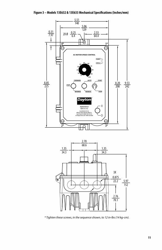
Figure 3 – Models 13E632 & 13E633 Mechanical Specifications (Inches/mm)
* Tighten these screws, in the sequence shown, to 12 in-lbs (14 kg-cm).
12
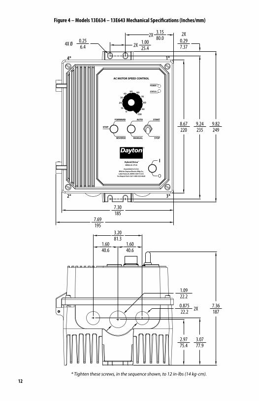
Figure 4 – Models 13E634 – 13E643 Mechanical Specifications (Inches/mm)
2.9775.4
3.0777.9
7.36187
3.2081.3
1.6040.6
1.6040.6
0.87522.2
1.0922.2
2X
8.67220
9.24235
9.82249
7.30185
7.69195
4X Ø 6.40.25 0.29
7.372X 25.4
2X 80.01.00
3.15 2X
4* 1*
2* 3*
NEMA 4X / IP 65
Hybrid Drive™
Assembled in U.S.A.
Mfd. for Dayton Electric Mfg. Co.,
Lake Forest, IL 60045-5201 U.S.A.
For Repair Parts Call 1-800-323-0620
* Tighten these screws, in the sequence shown, to 12 in-lbs (14 kg-cm).
13
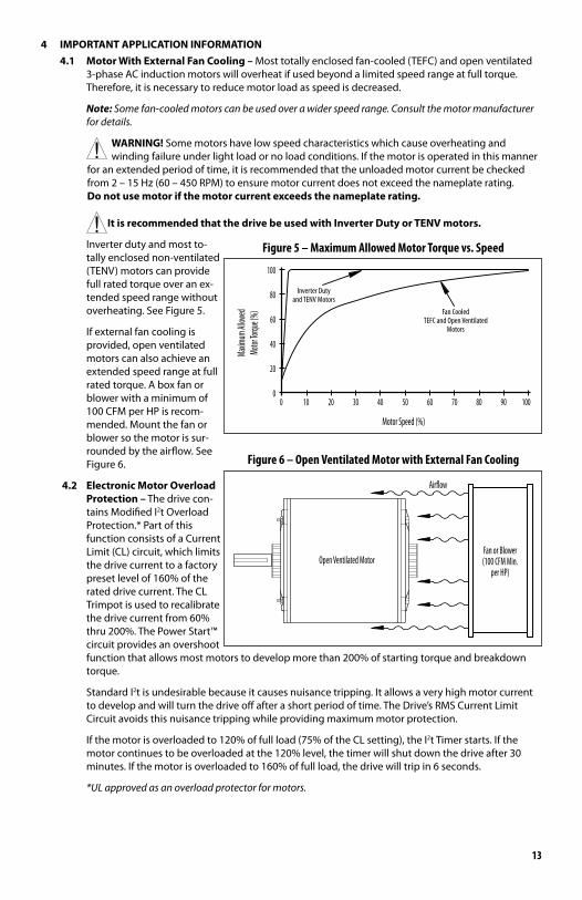
4 IMPORTANT APPLICATION INFORMATION4.1 MotorWithExternalFanCooling– Most totally enclosed fan-cooled (TEFC) and open ventilated
3-phase AC induction motors will overheat if used beyond a limited speed range at full torque. Therefore, it is necessary to reduce motor load as speed is decreased.
Note: Some fan-cooled motors can be used over a wider speed range. Consult the motor manufacturer for details.
WARNING! Some motors have low speed characteristics which cause overheating and winding failure under light load or no load conditions. If the motor is operated in this manner
for an extended period of time, it is recommended that the unloaded motor current be checked from 2 – 15 Hz (60 – 450 RPM) to ensure motor current does not exceed the nameplate rating. Donotusemotorifthemotorcurrentexceedsthenameplaterating.
It is recommended that the drive be used with Inverter Duty or TENV motors.
Inverter duty and most to-tally enclosed non-ventilated (TENV) motors can provide full rated torque over an ex-tended speed range without overheating. See Figure 5.
If external fan cooling is provided, open ventilated motors can also achieve an extended speed range at full rated torque. A box fan or blower with a minimum of 100 CFM per HP is recom-mended. Mount the fan or blower so the motor is sur-rounded by the airflow. See Figure 6.
4.2 Electronic Motor Overload Protection – The drive con-tains Modified I2t Overload Protection.* Part of this function consists of a Current Limit (CL) circuit, which limits the drive current to a factory preset level of 160% of the rated drive current. The CL Trimpot is used to recalibrate the drive current from 60% thru 200%. The Power Start™ circuit provides an overshoot function that allows most motors to develop more than 200% of starting torque and breakdown torque.
Standard I2t is undesirable because it causes nuisance tripping. It allows a very high motor current to develop and will turn the drive off after a short period of time. The Drive’s RMS Current Limit Circuit avoids this nuisance tripping while providing maximum motor protection.
If the motor is overloaded to 120% of full load (75% of the CL setting), the I2t Timer starts. If the motor continues to be overloaded at the 120% level, the timer will shut down the drive after 30 minutes. If the motor is overloaded to 160% of full load, the drive will trip in 6 seconds.
*UL approved as an overload protector for motors.
and TENV MotorsInverter Duty
Maxim
um All
owed
Motor
Torqu
e (%)
TEFC and Open VentilatedMotors
Fan Cooled
10060 70 805030 40100 20 90
Motor Speed (%)
40
0
20
60
80
100
Figure 5 – Maximum Allowed Motor Torque vs. Speed
Open Ventilated MotorFan or Blower(100 CFM Min.
per HP)
Airow
Figure 6 – Open Ventilated Motor with External Fan Cooling
14
5 WIRING INSTRUCTIONS WARNING! Read Safety Warning, on page 5, before using the drive. Disconnect main
power before making connections to the drive. To avoid electric shock, be sure to properly ground the drive. It is highly recommended that the Signal Isolator with Power Supply (Model No. 13E666) be installed when using signal following.
WARNING! HIGH VOLTAGE – REMOTE CONNECTIONS OF POTENTIOMETER, SWITCHES, ETC., WILL HAVE WIRING THAT IS AT LINE POTENTIAL. IT IS REQUIRED THAT THE SIGNAL ISOLATOR
BE INSTALLED FOR REMOTE CONNECTIONS.
Application Note – To avoid erratic operation, do not bundle the AC line and motor wires with each other or with wires from signal following, start/stop contacts, or any other signal wires. Also, do not bundle motor wires from multiple drives in the same conduit. Use shielded cables on all signal wiring over 12” (30 cm). The shield should be earth grounded on the drive side only. Wire the drive in accor-dance with the National Electrical Code requirements and other local codes that may apply.
Be sure to properly fuse each AC line conductor that is not at ground potential. Do not fuse neutral or grounded conductors. A separate AC line switch or contactor must be wired as a disconnect so that each ungrounded conductor is opened. For fuse or circuit breaker selection, see Table 5. Also see Section 11 on pages 22 - 23.
To maintain the watertight integrity of the drive, be sure to use suitable watertight connectors and wiring which are appropriate for the application. Models 13E632 & 13E633 contain three holes for standard 1/2” liquidtight fittings (not supplied). One watertight plug is provided, if only one knockout is used. Models 13E634 – 13E643 contain three holes for standard 1/2” liquidtight fittings (not supplied) and one mounting hole for standard 3/4” liquidtight fitting (not supplied). Two watertight plugs are provided, if only one knockout is used.
The drive is designed with a hinged case so that when the front cover is open, all wiring stays intact. To open the cover, the four screws must be loosened so they are no longer engaged in the case bottom. After mounting and wiring, close the cover making sure that the wires do not get caught or crimped as the cover is closed. Tighten the four screws so that the gasket is slightly compressed. The recommended tightening torque is 12 in-lbs (14 kg-cm). See Figure 3 on page 11 and Figure 4 on page 12 for the tightening sequence. Do not overtighten.
Table 5 – Terminal Block Wiring InformationTerminal
Block Description ModelMaximum Wire Size (Cu) Recommended Tightening Torque
AWG mm2 in-lbs kg-cm
TB1 AC Line Input and Motor Wiring13E632 & 13E633 12 3.3 7 8
13E634 – 13E643 12 3.3 12 14
TB2 Run/Fault Relay Output Contacts All 16 1.3 3.5 3
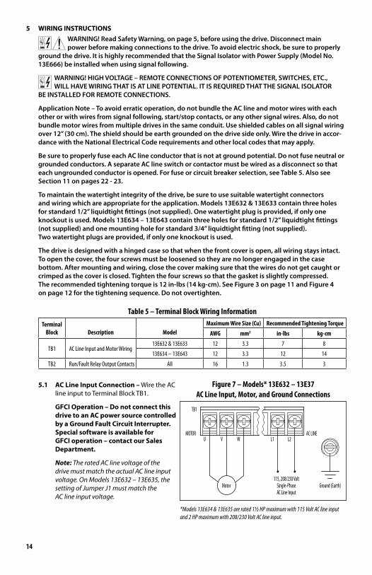
5.1 AC Line Input Connection – Wire the AC line input to Terminal Block TB1.
GFCI Operation – Do not connect this drive to an AC power source controlled by a Ground Fault Circuit Interrupter. Special software is available for GFCI operation – contact our Sales Department.
Note: The rated AC line voltage of the drive must match the actual AC line input voltage. On Models 13E632 – 13E635, the setting of Jumper J1 must match the AC line input voltage.
AC LINEMOTOR
Motor
VU W
AC Line Input
115, 208/230 VoltSingle-Phase Ground (Earth)
L1 L2
TB1
Figure 7 – Models* 13E632 – 13E37AC Line Input, Motor, and Ground Connections
*Models 13E634 & 13E635 are rated 11⁄2 HP maximum with 115 Volt AC line input and 2 HP maximum with 208/230 Volt AC line input.
15
Models 13E632 – 13E635: Designed to accept single-phase AC line input only (Terminals “L1”, “L2”). Rated for 208/230 Volt AC line input with Jumper J1 set to the “230V” position (factory setting). Rated for 115 Volt AC line input with Jumper J1 set to the “115V” position. See Figure 7 on page 14.
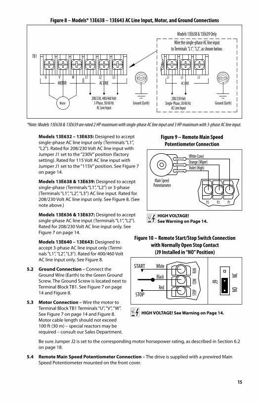
Models 13E638 & 13E639: Designed to accept single-phase (Terminals “L1”, “L2”) or 3-phase (Terminals “L1”, “L2”, “L3”) AC line input. Rated for 208/230 Volt AC line input only. See Figure 8. (See note above.)
Models 13E636 & 13E637: Designed to accept single-phase AC line input (Terminals “L1”, “L2”). Rated for 208/230 Volt AC line input only. See Figure 7 on page 14.
Models 13E640 – 13E643: Designed to accept 3-phase AC line input only (Termi-nals “L1”, “L2”, “L3”). Rated for 400/460 Volt AC line input only. See Figure 8.
5.2 Ground Connection – Connect the Ground Wire (Earth) to the Green Ground Screw. The Ground Screw is located next to Terminal Block TB1. See Figure 7 on page 14 and Figure 8.
5.3 Motor Connection – Wire the motor to Terminal Block TB1 Terminals “U”, “V”, “W”. See Figure 7 on page 14 and Figure 8. Motor cable length should not exceed 100 ft (30 m) – special reactors may be required – consult our Sales Department.
Be sure Jumper J2 is set to the corresponding motor horsepower rating, as described in Section 6.2 on page 18.
5.4 Remote Main Speed Potentiometer Connection – The drive is supplied with a prewired Main Speed Potentiometer mounted on the front cover.
*Note: Models 13E638 & 13E639 are rated 2 HP maximum with single-phase AC line input and 3 HP maximum with 3-phase AC line input.
to Terminals "L1", "L2", as shown below.
Models 13E638 & 13E639 Only
Wire the single-phase AC line input
208/230 Volt
AC Line InputSingle-Phase, 50/60 Hz Ground (Earth)
L3L2L1AC LINE
Ground (Earth)3-Phase, 50/60 Hz208/230, 400/460 Volt
MotorAC Line Input
WU VMOTOR
TB1
L1 L3L2AC LINE
Figure 8 – Models* 13E638 – 13E643 AC Line Input, Motor, and Ground Connections
Figure 9 – Remote Main SpeedPotentiometer Connection
Main SpeedPotentiometer
Orange (Wiper)Violet (High)
White (Low)
P1P2P3
HIGH VOLTAGE! See Warning on Page 14.
Figure 10 – Remote Start/Stop Switch Connectionwith Normally Open Stop Contact
(J9 Installed in “NO” Position)
COMBlack
STOP STOPRed
START
RUNWhite
NO
J9
NC
HIGH VOLTAGE! See Warning on Page 14.
16
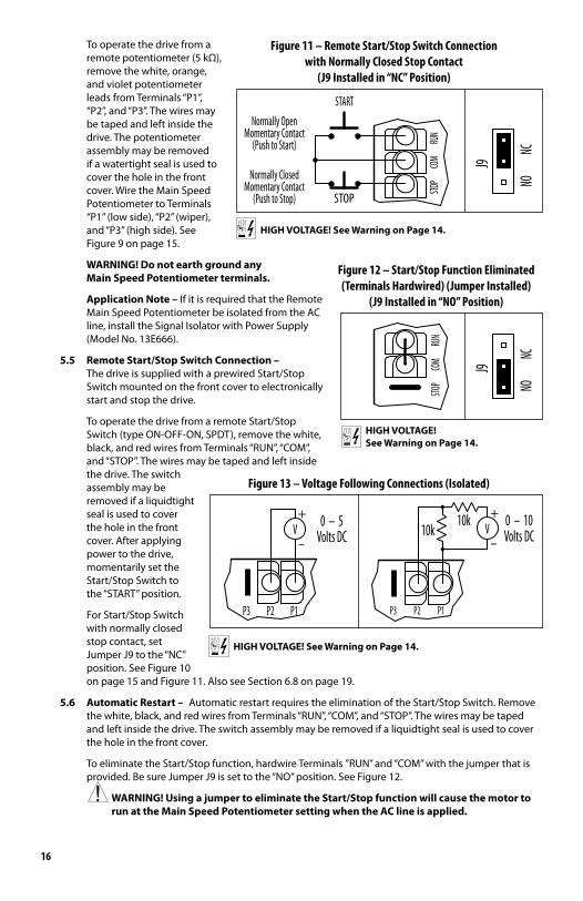
To operate the drive from a remote potentiometer (5 kΩ), remove the white, orange, and violet potentiometer leads from Terminals “P1”, “P2”, and “P3”. The wires may be taped and left inside the drive. The potentiometer assembly may be removed if a watertight seal is used to cover the hole in the front cover. Wire the Main Speed Potentiometer to Terminals “P1” (low side), “P2” (wiper), and “P3” (high side). See Figure 9 on page 15.
WARNING! Do not earth ground any Main Speed Potentiometer terminals.
Application Note – If it is required that the Remote Main Speed Potentiometer be isolated from the AC line, install the Signal Isolator with Power Supply (Model No. 13E666).
5.5 Remote Start/Stop Switch Connection – The drive is supplied with a prewired Start/Stop Switch mounted on the front cover to electronically start and stop the drive.
To operate the drive from a remote Start/Stop Switch (type ON-OFF-ON, SPDT), remove the white, black, and red wires from Terminals “RUN”, “COM”, and “STOP”. The wires may be taped and left inside the drive. The switch assembly may be removed if a liquidtight seal is used to cover the hole in the front cover. After applying power to the drive, momentarily set the Start/Stop Switch to the “START” position.
For Start/Stop Switch with normally closed stop contact, set Jumper J9 to the “NC” position. See Figure 10 on page 15 and Figure 11. Also see Section 6.8 on page 19.
5.6 Automatic Restart – Automatic restart requires the elimination of the Start/Stop Switch. Remove the white, black, and red wires from Terminals “RUN”, “COM”, and “STOP”. The wires may be taped and left inside the drive. The switch assembly may be removed if a liquidtight seal is used to cover the hole in the front cover.
To eliminate the Start/Stop function, hardwire Terminals ”RUN” and “COM” with the jumper that is provided. Be sure Jumper J9 is set to the “NO” position. See Figure 12.
WARNING! Using a jumper to eliminate the Start/Stop function will cause the motor to run at the Main Speed Potentiometer setting when the AC line is applied.
HIGH VOLTAGE! See Warning on Page 14.
NO
J9
NC
COM
(Push to Stop)
Normally ClosedMomentary Contact
STOP
STOP
Normally OpenMomentary Contact
(Push to Start) RUN
START
Figure 11 – Remote Start/Stop Switch Connectionwith Normally Closed Stop Contact
(J9 Installed in “NC” Position)
NO
J9
NC
COM
STOP
RUN
HIGH VOLTAGE! See Warning on Page 14.
Figure 12 – Start/Stop Function Eliminated(Terminals Hardwired) (Jumper Installed)
(J9 Installed in “NO” Position)
HIGH VOLTAGE! See Warning on Page 14.
0 – 5Volts DC
P2P3 P1
V-
+ 0 – 10Volts DC
P2P3 P1
10k V10k-
+
Figure 13 – Voltage Following Connections (Isolated)
17
5.7 Voltage Following Connection – An isolated* 0 – 5 Volt DC analog signal input can also be used to control motor speed in lieu of the Main Speed Potentiometer. The drive output will linearly follow the analog signal input. Wire the signal input positive lead (+) to Terminal “P2” and the negative lead (-) to Terminal “P1”. With external circuitry, a 0 – 10 Volt DC analog signal can also be used. See Figure 13.
*If a non-isolated signal is used, install the Signal Isolator with Power Supply (Model No. 13E666). The Signal Isolator accepts voltage (0 to ±2.5 thru 0 to ±25 Volts DC) or current (4 – 20 mA DC) signal inputs. See Table 2 on page 8. See Appendix A on page 27 for Signal Isolator information.
Note: For signal following operation, the Minimum Speed Trimpot (MIN) must be set fully counterclockwise.
WARNING! The signal input must be isolated from the AC line. Earth grounding signal wir-
ing will damage the drive and void the warranty. It is highly recommended that the Signal Isola-torwithPowerSupply(ModelNo.13E666)beinstalled when using signal following.
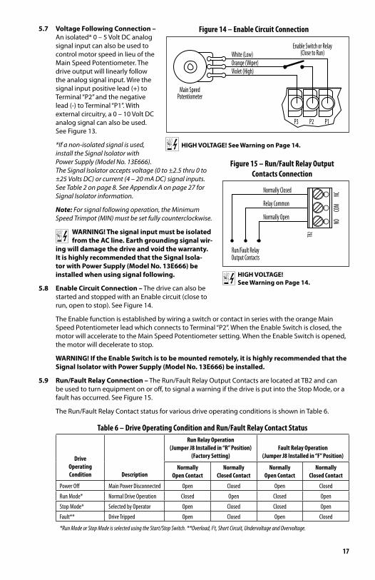
5.8 Enable Circuit Connection – The drive can also be started and stopped with an Enable circuit (close to run, open to stop). See Figure 14.
The Enable function is established by wiring a switch or contact in series with the orange Main Speed Potentiometer lead which connects to Terminal “P2”. When the Enable Switch is closed, the motor will accelerate to the Main Speed Potentiometer setting. When the Enable Switch is opened, the motor will decelerate to stop.
WARNING! If the Enable Switch is to be mounted remotely, it is highly recommended that the SignalIsolatorwithPowerSupply(ModelNo.13E666)beinstalled.
5.9 Run/Fault Relay Connection – The Run/Fault Relay Output Contacts are located at TB2 and can be used to turn equipment on or off, to signal a warning if the drive is put into the Stop Mode, or a fault has occurred. See Figure 15.
The Run/Fault Relay Contact status for various drive operating conditions is shown in Table 6.
Table 6 – Drive Operating Condition and Run/Fault Relay Contact Status
DriveOperatingCondition Description
Run Relay Operation(Jumper J8 Installed in “R” Position)
(Factory Setting)Fault Relay Operation
(Jumper J8 Installed in “F” Position)
NormallyOpen Contact
NormallyClosed Contact
NormallyOpen Contact
NormallyClosed Contact
Power Off Main Power Disconnected Open Closed Open Closed
Run Mode* Normal Drive Operation Closed Open Closed Open
Stop Mode* Selected by Operator Open Closed Closed Open
Fault** Drive Tripped Open Closed Open Closed
*Run Mode or Stop Mode is selected using the Start/Stop Switch. **Overload, I2t, Short Circuit, Undervoltage and Overvoltage.
HIGH VOLTAGE! See Warning on Page 14.
Main SpeedPotentiometer
Enable Switch or Relay
Orange (Wiper)Violet (High)
White (Low) (Close to Run)
P1P2P3
Figure 14 – Enable Circuit Connection
HIGH VOLTAGE! See Warning on Page 14.
Output ContactsRun/Fault Relay
Normally Closed
Relay Common
Normally Open
NCNO
TB2
COM
Figure 15 – Run/Fault Relay OutputContacts Connection
18
6 SETTING SELECTABLE JUMPERS The drive has customer selectable
jumpers which must be set before the drive can be used. For the location of jumpers, see Figure 2 on page 9.
WARNING! HIGH VOLTAGE Disconnect the AC line
before changing position of jumpers.
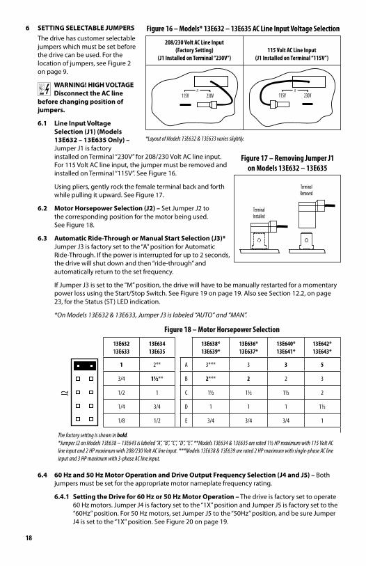
6.1 Line Input Voltage Selection(J1)(Models 13E632 – 13E635 Only) – Jumper J1 is factory installed on Terminal “230V” for 208/230 Volt AC line input. For 115 Volt AC line input, the jumper must be removed and installed on Terminal “115V”. See Figure 16.
Using pliers, gently rock the female terminal back and forth while pulling it upward. See Figure 17.
6.2 MotorHorsepowerSelection(J2)– Set Jumper J2 to the corresponding position for the motor being used. See Figure 18.
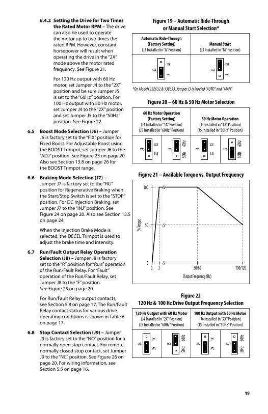
6.3 AutomaticRide-ThroughorManualStartSelection(J3)* Jumper J3 is factory set to the “A” position for Automatic Ride-Through. If the power is interrupted for up to 2 seconds, the drive will shut down and then “ride-through” and automatically return to the set frequency.
If Jumper J3 is set to the “M” position, the drive will have to be manually restarted for a momentary power loss using the Start/Stop Switch. See Figure 19 on page 19. Also see Section 12.2, on page 23, for the Status (ST) LED indication.
*On Models 13E632 & 13E633, Jumper J3 is labeled “AUTO” and “MAN”.
Figure 18 – Motor Horsepower Selection
13E632 13E633
13E634 13E635
13E638* 13E639*
13E636* 13E637*
13E640* 13E641*
13E642* 13E643*
J2
1 2** A 3*** 3 3 5
3/4 11/2** B 2*** 2 2 3
1/2 1 C 11/2 11/2 11/2 2
1/4 3/4 D 1 1 1 11/2
1/8 1/2 E 3/4 3/4 3/4 1
The factory setting is shown in bold.*Jumper J2 on Models 13E638 – 13E643 is labeled “A”, “B”, “C”, “D”, “E”. **Models 13E634 & 13E635 are rated 11⁄2 HP maximum with 115 Volt AC line input and 2 HP maximum with 208/230 Volt AC line input. ***Models 13E638 & 13E639 are rated 2 HP maximum with single-phase AC line input and 3 HP maximum with 3-phase AC line input.
6.4 60Hzand50HzMotorOperationandDriveOutputFrequencySelection(J4andJ5)– Both jumpers must be set for the appropriate motor nameplate frequency rating.
6.4.1 Setting the Drive for 60 Hz or 50 Hz Motor Operation – The drive is factory set to operate 60 Hz motors. Jumper J4 is factory set to the “1X” position and Jumper J5 is factory set to the “60Hz” position. For 50 Hz motors, set Jumper J5 to the “50Hz” position, and be sure Jumper J4 is set to the “1X” position. See Figure 20 on page 19.
115VJ1
230VJ1
115V 230V
208/230 Volt AC Line Input(Factory Setting)
(J1 Installed on Terminal “230V”)115 Volt AC Line Input
(J1 Installed on Terminal “115V”)
Figure 16 – Models* 13E632 – 13E635 AC Line Input Voltage Selection
*Layout of Models 13E632 & 13E633 varies slightly.
TerminalInstalled
RemovedTerminal
Figure 17 – Removing Jumper J1on Models 13E632 – 13E635
19
6.4.2 Setting the Drive for Two Times the Rated Motor RPM – The drive can also be used to operate the motor up to two times the rated RPM. However, constant horsepower will result when operating the drive in the “2X” mode above the motor rated frequency. See Figure 21.
For 120 Hz output with 60 Hz motor, set Jumper J4 to the “2X” position and be sure Jumper J5 is set to the “60Hz” position. For 100 Hz output with 50 Hz motor, set Jumper J4 to the “2X” position and set Jumper J5 to the “50Hz” position. See Figure 22.
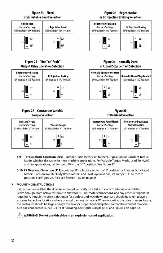
6.5 BoostModeSelection(J6)– Jumper J6 is factory set to the “FIX” position for Fixed Boost. For Adjustable Boost using the BOOST Trimpot, set Jumper J6 to the “ADJ” position. See Figure 23 on page 20. Also see Section 13.8 on page 26 for the BOOST Trimpot range.
6.6 BrakingModeSelection(J7)– Jumper J7 is factory set to the “RG” position for Regenerative Braking when the Start/Stop Switch is set to the “STOP” position. For DC Injection Braking, set Jumper J7 to the “INJ” position. See Figure 24 on page 20. Also see Section 13.5 on page 24.
When the Injection Brake Mode is selected, the DECEL Trimpot is used to adjust the brake time and intensity.
6.7 Run/Fault Output Relay Operation Selection(J8)– Jumper J8 is factory set to the “R” position for “Run” operation of the Run/Fault Relay. For “Fault” operation of the Run/Fault Relay, set Jumper J8 to the “F” position. See Figure 25 on page 20.
For Run/Fault Relay output contacts, see Section 5.8 on page 17. The Run/Fault Relay contact status for various drive operating conditions is shown in Table 6 on page 17.
6.8 StopContactSelection(J9)– Jumper J9 is factory set to the “NO” position for a normally open stop contact. For remote normally closed stop contact, set Jumper J9 to the “NC” position. See Figure 26 on page 20. For wiring information, see Section 5.5 on page 16.
Automatic Ride-Through(Factory Setting)
(J3 Installed in “A” Position)Manual Start
(J3 Installed in “M” Position)
A
J3
M
A
J3
M
Figure 19 – Automatic Ride-Throughor Manual Start Selection*
*On Models 13E632 & 13E633, Jumper J3 is labeled “AUTO” and “MAN”.
60 Hz Motor Operation(Factory Setting)
(J4 Installed in “1X” Position)(J5 Installed in “60Hz” Position)
50 Hz Motor Operation(J4 Installed in “1X” Position)
(J5 Installed in “50Hz” Position)
50HzJ5
60Hz
2X
J4
1X
50HzJ5
60Hz
2X
J4
1X
Figure 20 – 60 Hz & 50 Hz Motor Selection
50/60
Output Frequency (Hz)
020
% Torq
ue
50
100/120
100
Figure 21 – Available Torque vs. Output Frequency
120 Hz Output with 60 Hz Motor(J4 Installed in “2X” Position)
(J5 Installed in “60Hz” Position)
100 Hz Output with 50 Hz Motor(J4 Installed in “2X” Position)
(J5 Installed in “50Hz” Position)
50HzJ5
60Hz
2X
J4
1X
50HzJ5
60Hz
2X
J4
1X
Figure 22120 Hz & 100 Hz Drive Output Frequency Selection
20
6.9 TorqueModeSelection(J10)– Jumper J10 is factory set to the “CT” position for Constant Torque Mode, which is desirable for most machine applications. For Variable Torque Mode, used for HVAC and fan applications, set Jumper J10 to the “VT” position. See Figure 27.
6.10 I2tOverloadSelection(J11)– Jumper J11 is factory set to the “1” position for Inverter Duty Rated Motors. For Non Inverter Duty Rated Motors and HVAC applications, set Jumper J11 to the “2” position. See Figure 28. Also see Section 13.7 on page 25.
7 MOUNTING INSTRUCTIONS It is recommended that the drive be mounted vertically on a flat surface with adequate ventilation.
Leave enough room below the drive to allow for AC line, motor connections, and any other wiring that is required. Although the drive is designed for outdoor and washdown use, care should be taken to avoid extreme hazardous locations where physical damage can occur. When mounting the drive in an enclosure, the enclosure should be large enough to allow for proper heat dissipation so that the ambient tempera-ture does not exceed 40 °C (104 °F) at full rating. See Figure 3 on page 11 and Figure 4 on page 12.
WARNING!Donotusethisdriveinanexplosion-proofapplication.
Fixed Boost(Factory Setting)
(J6 Installed in “FIX” Position)Adjustable Boost
(J6 Installed in “ADJ” Position)
ADJJ6
FIX
ADJJ6
FIX
Figure 23 – Fixed or Adjustable Boost Selection
Regenerative Braking(Factory Setting)
(J7 Installed in “RG” Position)DC Injection Braking
(J7 Installed in “INJ” Position)
INJ
J7
RG
INJ
J7
RGINJ
J7
RG
Figure 24 – Regenerative or DC Injection Braking Selection
Regenerative Braking(Factory Setting)
(J7 Installed in “RG” Position)DC Injection Braking
(J7 Installed in “INJ” Position)
F
J8
R
F
J8
RFigure 25 – “Run” or “Fault”
Output Relay Operation Selection
Normally Open Stop Contact(Factory Setting)
(J9 Installed in “NO” Position)Normally Closed Stop Contact
(J9 Installed in “NC” Position)
NO
J9
NC
NO
J9
NC
Figure 26 – Normally Openor Closed Stop Contact Selection
Constant Torque(Factory Setting)
(J10 Installed in “CT” Position)Variable Torque
(J10 Installed in “VT” Position)
VT
J10
CT
J10
CTVT
Figure 27 – Constant or Variable Torque Selection
Inverter Duty Rated Motor(Factory Setting)
(J11 Installed in “1” Position)
Non Inverter Duty RatedMotor Operation
(J11 Installed in “2” Position)
1
J11
2
J11
21
Figure 28 I2t Overload Selection
21
Chassis
P3Cha
ssis
Machi
ne Equ
ipment
or Fra
me
Adjus
table F
requen
cy Dri
ve
(Main
Powe
r Disco
nnect
ed)to A
C Line
Inputs
Connec
t Hi-P
ot
L2L1
P2P1
Auxili
ary Eq
uipme
nt
L3 Signal
Inputs
L2
H. V.
AC Lin
e Inpu
t
MAX
ZERO
L1
RESE
T
RETU
RN
10m
A0m
A
VOLTA
GETE
ST
AC KI
LOVO
LTS
LEAK
AGE
1
03
2
High V
oltage
Diele
ctric W
ithsta
nd Tes
ter (H
i-Pot T
ester)
Motor
Wires
WV
Frame
Connec
t All D
rive Ter
minal
s Toget
her
U
(Main
Powe
r Disco
nnect
ed)
Figu
re 29
– Ty
pica
l Hi-P
ot Te
st Se
tup
22
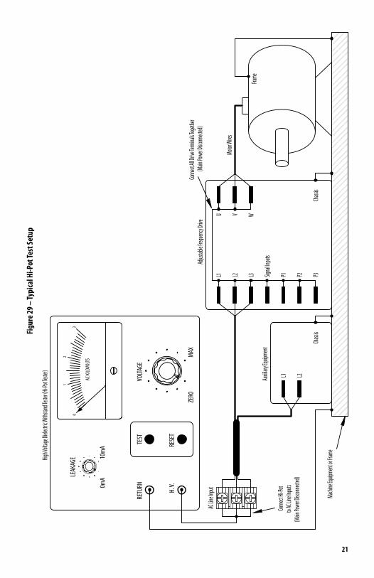
8 RECOMMENDEDHIGHVOLTAGEDIELECTRICWITHSTANDTESTING(HI-POTTESTING) Testing agencies such as UL, CSA, VDE, etc., usually require that equipment undergo a hi-pot test. In order
to prevent catastrophic damage to the drive which has been installed in the equipment, the following procedure is recommended. A typical hi-pot test setup is shown in Figure 29 on page 21. All drives have been factory hi-pot tested in accordance with UL requirements.
WARNING! All equipment AC line inputs must be disconnected from the AC power.
8.1 Connect all equipment AC power input lines together and connect them to the H.V. lead of the hi-pot tester. Connect the RETURN lead of the hi-pot tester to the frame on which the drive and other auxiliary equipment are mounted.
8.2 The hi-pot tester must have an automatic ramp-up to the test voltage and an automatic ramp-down to zero voltage.
Note: If the hi-pot tester does not have automatic ramping, then the hi-pot output must be manually increased to the test voltage and then manually reduced to zero. This procedure must be followed for each machine to be tested. A suggested hi-pot tester is Slaughter Model 2550.
CAUTION! Instantly applying the hi-pot voltage will cause irreversible damage to the drive, which will void the warranty.
9 RECONDITIONING THE BUS CAPACITORS If this drive has been in storage for over one year it is necessary to recondition the power supply bus
capacitors. To recondition the bus capacitors, apply the AC Line, with the drive in the Stop Mode, for a minimum of one hour. Not following this procedure will cause the bus capacitors to fail.
10 DRIVE OPERATION10.1 Start-Up Procedure – After the drive has been properly setup (jumpers and trimpots set to the
desired positions) and wiring completed, the start-up procedure can begin. If the AC power has been properly brought to the drive, the power (PWR) LED will illuminate green. The status (ST) LED will indicate drive status, as described in Section 12.2 on page 23.
To start the drive, momentarily set the Start/Stop Switch to the “START” position. The motor will begin to accelerate to the set speed.
WARNING! Using a jumper to eliminate the start/stop function will cause the motor to run at the Main Speed Potentiometer setting when the AC line is applied. See Section 10.2.
Note: If the motor rotates in the incorrect direction, it will be necessary to disconnect the AC line, reverse any two motor leads, and repeat the start-up procedure.
10.2 Restarting the Drive After a Fault has been Cleared1,2 – The drive monitors four faults: Undervoltage, Overvoltage, Short Circuit at the motor (phase-to-phase), and Overload. See Section 12.2 on page 23 for the Status (ST) LED indication. Also see Section 6.3 on page 18 for Automatic Ride-Through or Manual Restart selection with Jumper J3.
To restart the drive after a fault has been cleared, use the Start/Stop Switch2,3.
If the Start/Stop Switch has been eliminated (bypassed), see Section 5.6 on page 16.4 The drive can be restarted (after the fault has been cleared) by disconnecting the AC power, and all LEDs are no longer illuminated, and then reconnecting the AC power.
Notes: 1. For an Overload Fault, be sure the fault has been cleared before restarting the drive. Check the motor current with an AC RMS responding ammeter. Also, the CL setting may be set too low. See Section 13.7 on page 25. 2. For an Overvoltage Fault, if the drive is set for Automatic Ride-Through, the drive will automatically restart when the AC line voltage returns to below the specified Overvoltage Trip Point. 3. If the Forward-Stop-Reverse Switch has been installed, it can be used to restart the drive. 4. If the Start/Stop Switch has been eliminated (bypassed), the AC line must be used to restart the drive after an Overload Fault has been cleared.
11 AC LINE FUSING The drive does not contain line fuses. Most electrical codes require that each ungrounded conductor
contain circuit protection. Do not fuse neutral or ground connections. It is recommended to install
23
a fuse (Littelfuse 312/314, Buss ABC, or equivalent) or a circuit breaker in series with each ungrounded conductor. Do not fuse motor leads. For the recommended fuse size, see Table 4 on page 10.
Wire the drive in accordance with the National Electrical Code requirements and other local codes that may apply to the application.
12 DIAGNOSTIC LEDs The drive contains two diagnostic LEDs mounted on the enclosure cover to display the drive’s
operational status.
12.1 PowerOnLED(PWR)– The “PWR” LED will illuminate green when the AC line is applied to the drive.
WARNING! Do not depend on the PWR LED as a guaranteed power off condition. Be sure the main power switch or circuit breaker is in the “OFF” position before
servicing this drive.
12.2 StatusLED(ST)– The “ST” LED is a tricolor LED which provides indication of a fault or abnormal condition. The information provided can be used to diagnose an installation problem such as incor-rect input voltage, overload condition, and drive output miswiring. It also provides a signal which informs the user that all drive and microcontroller operating parameters are normal. Table 7, summarizes the “ST” LED functions.
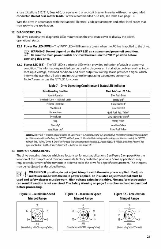
Table 7 – Drive Operating Condition and Status LED IndicatorDrive Operating Condition Flash Rate1 and LED Color
Normal Operation Slow Flash Green
Overload (120% – 160% Full Load) Steady Red2
I2t (Drive Timed Out) Quick Flash Red2
Short Circuit Slow Flash Red
Undervoltage Quick Flash Red / Yellow3
Overvoltage Slow Flash Red / Yellow3
Stop Steady Yellow
Stand-By4 Slow Flash Yellow
Input Phase Loss5 Rapid Flash Yellow
Notes: 1. Slow Flash = 1 second on and 1 second off. Quick Flash = 0.25 second on and 0.25 second off. 2. When the Overload is removed, before the I2t times out and trips the drive, the “ST” LED will flash green. 3. When the Undervoltage or Overvoltage condition is corrected, the “ST” LED will flash Red / Yellow / Green. 4. Only if the Forward-Stop-Reverse Switch is installed. 5. Models 13E638 & 13E639, with three-Phase AC line input, and Models 13E640 – 13E643. Rapid Flash = 4 mSec on and 6 mSec off.
13 TRIMPOT ADJUSTMENTS The drive contains trimpots which are factory set for most applications. See Figure 2 on page 9 for the
location of the trimpots and their approximate factory calibrated positions. Some applications may require readjustment of the trimpots in order to tailor the drive for a specific requirement. The trimpots may be readjusted as described below.
WARNING! If possible, do not adjust trimpots with the main power applied. If adjust-ments are made with the main power applied, an insulated adjustment tool must be
usedandsafetyglassesmustbeworn.Highvoltageexistsinthisdrive.Fireand/orelectrocutioncanresultifcautionisnotexercised.TheSafetyWarningonpage5mustbereadandunderstoodbefore proceeding.
(Shown Factory Set to 0% Frequency Setting)
0MIN
40
15 35
30
Figure 30 – Minimum SpeedTrimpot Range
(Shown Factory Set to 100% Frequency Setting)
70MAX
110
75 90100
80
Figure 31 – Maximum Speed Trimpot Range
0.3
(Shown Factory Set to 1.5 Seconds)ACCEL
20
31.5
17
10
Figure 32 – Acceleration Trimpot Range
24
13.1 MinimumSpeed(MIN)– Sets the minimum speed of the motor. The MIN Trimpot is factory set to 0% of frequency setting. For a higher minimum speed setting, rotate the MIN Trimpot clockwise. See Figure 30 on page 23.
13.2 MaximumSpeed(MAX)– Sets the maximum speed of the motor. The MAX Trimpot is factory set to 100% of frequency setting. For a lower maximum speed setting, rotate the MAX Trimpot counterclockwise. For a higher maximum speed setting, rotate the MAX Trimpot clockwise. See Figure 31 on page 23.
13.3 Acceleration(ACCEL)– Sets the amount of time for the motor to accelerate from zero speed to full speed. The ACCEL Trimpot is factory set to 1.5 seconds. For a longer acceleration time, rotate the ACCEL Trimpot clockwise. For more rapid acceleration, rotate the ACCEL Trimpot counterclockwise. See Figure 32 on page 23.
Note: Rapid acceleration settings may cause the current limit circuit to activate, which will extend the acceleration time.
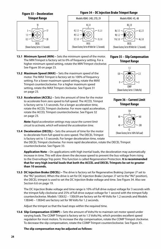
13.4 Deceleration(DECEL)– Sets the amount of time for the motor to decelerate from full speed to zero speed. The DECEL Trimpot is factory set to 1.5 seconds. For longer deceleration time, rotate the DECEL Trimpot clockwise. For more rapid deceleration, rotate the DECEL Trimpot counterclockwise. See Figure 33.
Application Note – On applications with high inertial loads, the deceleration may automatically increase in time. This will slow down the decrease speed to prevent the bus voltage from rising to the Overvoltage Trip point. This function is called Regeneration Protection. It is recommended that for very high inertial loads that both the ACCEL and DECEL Trimpots be set to greater than 10 seconds.
13.5 DCInjectionBrake(DECEL)– The drive is factory set for Regenerative Braking (Jumper J7 set to the “RG” position). When the drive is set for DC Injection Brake (Jumper J7 set to the “INJ” position), the DECEL trimpot is used to set the DC Injection Brake voltage and time. See Figure 34. Also see Section 6.6 on page 19.
The DC Injection Brake voltage and time range is 10% of full drive output voltage for 3 seconds with the trimpot fully clockwise and 25% of full drive output voltage for 1 second with the trimpot fully counterclockwise. Models 13E632 – 13E639 are factory set for 49 Volts for 1.2 seconds and Models 13E640 – 13E643 are factory set for 98 Volts for 1.2 seconds.
Adjust the trimpot so that the load stops within the required time.
13.6 SlipCompensation(COMP)– Sets the amount of Volts/Hz to maintain set motor speed under varying loads. The COMP Trimpot is factory set to 1.5 Volts/Hz, which provides excellent speed regulation for most motors. To increase the slip compensation, rotate the COMP Trimpot clockwise. To decrease the slip compensation, rotate the COMP Trimpot counterclockwise. See Figure 35.
The slip compensation may be adjusted as follows:
0.3
(Shown Factory Set to 1.5 Seconds)DECEL
20
31.5
17
10
Figure 33 – Deceleration Trimpot Range
(Shown Factory Set to 49 Volts for 1.2 Seconds)
57, 1.0DECEL
23, 3.0
43, 1.549, 1.2
31, 2.5
40, 2.0
(Shown Factory Set to 98 Volts for 1.2 Seconds)
114, 1.0DECEL
46, 3.0
86, 1.598, 1.2
62, 2.5
80, 2.0
Models KBAC-24D, 27D, 29 Models KBAC-45, 48
Figure 34 – DC Injection Brake Trimpot Range
COMP(Shown Factory Set to 1.5 Volts/Hz)
0
0.8
3
2.3
1.5
Figure 35 – Slip Compensation Trimpot Range
CL(Shown Factory Set to 160% Full Load)
40 200
80 160
120
Figure 36 – Current Limit Trimpot Range
25
1. Wire an AC RMS ammeter in series with one motor phase.
2. Run the motor and set the unloaded speed to approximately 50% (900 RPM on 4-pole 1500/1725 RPM motors).
3. Using a tachometer, record the unloaded speed.
4. Load the motor to the nameplate rated current (AC Amps).
5. Adjust the COMP Trimpot until the loaded RPM is equal to the unloaded RPM.
6. The motor is now compensated to provide constant speed under varying loads.
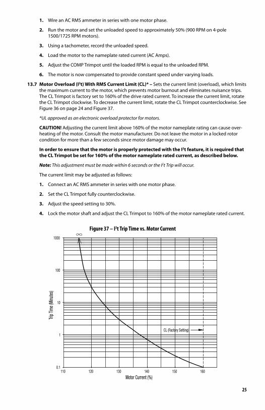
13.7 MotorOverload(I2t)WithRMSCurrentLimit(CL)*– Sets the current limit (overload), which limits the maximum current to the motor, which prevents motor burnout and eliminates nuisance trips. The CL Trimpot is factory set to 160% of the drive rated current. To increase the current limit, rotate the CL Trimpot clockwise. To decrease the current limit, rotate the CL Trimpot counterclockwise. See Figure 36 on page 24 and Figure 37.
*UL approved as an electronic overload protector for motors.
CAUTION! Adjusting the current limit above 160% of the motor nameplate rating can cause over-heating of the motor. Consult the motor manufacturer. Do not leave the motor in a locked rotor condition for more than a few seconds since motor damage may occur.
In order to ensure that the motor is properly protected with the I2t feature, it is required that the CL Trimpot be set for 160% of the motor nameplate rated current, as described below.
Note: This adjustment must be made within 6 seconds or the I2t Trip will occur.
The current limit may be adjusted as follows:
1. Connect an AC RMS ammeter in series with one motor phase.
2. Set the CL Trimpot fully counterclockwise.
3. Adjust the speed setting to 30%.
4. Lock the motor shaft and adjust the CL Trimpot to 160% of the motor nameplate rated current.
Trip T
ime (
Minu
tes)
CL (Factory Setting)
140110 120 1300.1
Motor Current (%)
1
160150
10
100
1000
Figure 37 – I2t Trip Time vs. Motor Current
26
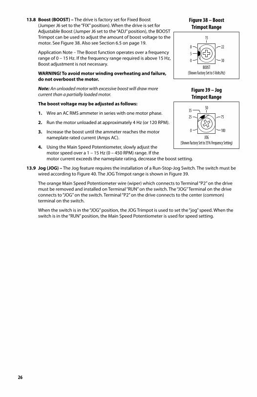
13.8 Boost(BOOST)– The drive is factory set for Fixed Boost (Jumper J6 set to the “FIX” position). When the drive is set for Adjustable Boost (Jumper J6 set to the “ADJ” position), the BOOST Trimpot can be used to adjust the amount of boost voltage to the motor. See Figure 38. Also see Section 6.5 on page 19.
Application Note – The Boost function operates over a frequency range of 0 – 15 Hz. If the frequency range required is above 15 Hz, Boost adjustment is not necessary.
WARNING! To avoid motor winding overheating and failure, do not overboost the motor.
Note: An unloaded motor with excessive boost will draw more current than a partially loaded motor.
The boost voltage may be adjusted as follows:
1. Wire an AC RMS ammeter in series with one motor phase.
2. Run the motor unloaded at approximately 4 Hz (or 120 RPM).
3. Increase the boost until the ammeter reaches the motor nameplate rated current (Amps AC).
4. Using the Main Speed Potentiometer, slowly adjust the motor speed over a 1 – 15 Hz (0 – 450 RPM) range. If the motor current exceeds the nameplate rating, decrease the boost setting.
13.9 Jog(JOG)– The Jog feature requires the installation of a Run-Stop-Jog Switch. The switch must be wired according to Figure 40. The JOG Trimpot range is shown in Figure 39.
The orange Main Speed Potentiometer wire (wiper) which connects to Terminal “P2” on the drive must be removed and installed on Terminal “RUN” on the switch. The “JOG” Terminal on the drive connects to “JOG” on the switch. Terminal “P2” on the drive connects to the center (common) terminal on the switch.
When the switch is in the “JOG” position, the JOG Trimpot is used to set the “jog” speed. When the switch is in the “RUN” position, the Main Speed Potentiometer is used for speed setting.
BOOST(Shown Factory Set to 5 Volts/Hz)
50
8
30
22
15
Figure 38 – BoostTrimpot Range
35
JOG(Shown Factory Set to 35% Frequency Setting)
0
25
100
75
50
Figure 39 – JogTrimpot Range
27
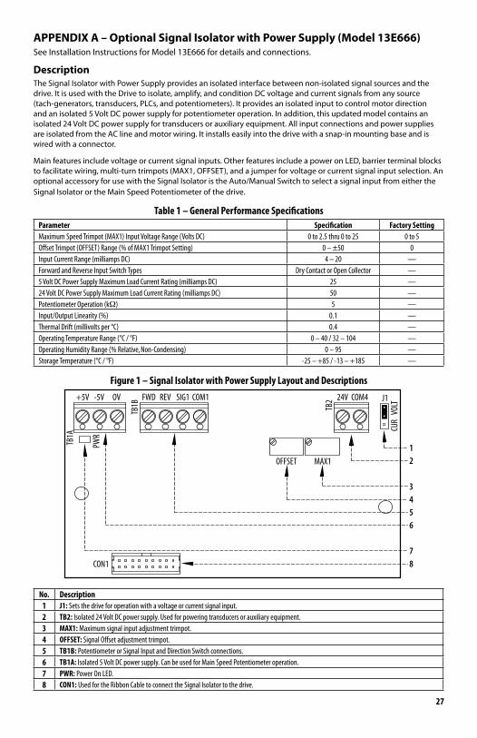
APPENDIXA–OptionalSignalIsolatorwithPowerSupply(Model13E666)See Installation Instructions for Model 13E666 for details and connections.
DescriptionThe Signal Isolator with Power Supply provides an isolated interface between non-isolated signal sources and the drive. It is used with the Drive to isolate, amplify, and condition DC voltage and current signals from any source (tach-generators, transducers, PLCs, and potentiometers). It provides an isolated input to control motor direction and an isolated 5 Volt DC power supply for potentiometer operation. In addition, this updated model contains an isolated 24 Volt DC power supply for transducers or auxiliary equipment. All input connections and power supplies are isolated from the AC line and motor wiring. It installs easily into the drive with a snap-in mounting base and is wired with a connector.
Main features include voltage or current signal inputs. Other features include a power on LED, barrier terminal blocks to facilitate wiring, multi-turn trimpots (MAX1, OFFSET), and a jumper for voltage or current signal input selection. An optional accessory for use with the Signal Isolator is the Auto/Manual Switch to select a signal input from either the Signal Isolator or the Main Speed Potentiometer of the drive.
Table 1 – General Performance SpecificationsParameter Specification Factory SettingMaximum Speed Trimpot (MAX1) Input Voltage Range (Volts DC) 0 to 2.5 thru 0 to 25 0 to 5Offset Trimpot (OFFSET) Range (% of MAX1 Trimpot Setting) 0 – ±50 0Input Current Range (milliamps DC) 4 – 20 —Forward and Reverse Input Switch Types Dry Contact or Open Collector —5 Volt DC Power Supply Maximum Load Current Rating (milliamps DC) 25 —24 Volt DC Power Supply Maximum Load Current Rating (milliamps DC) 50 —Potentiometer Operation (kΩ) 5 —Input/Output Linearity (%) 0.1 —Thermal Drift (millivolts per °C) 0.4 —Operating Temperature Range (°C / °F) 0 – 40 / 32 – 104 —Operating Humidity Range (% Relative, Non-Condensing) 0 – 95 —Storage Temperature (°C / °F) -25 – +85 / -13 – +185 —
Figure 1 – Signal Isolator with Power Supply Layout and Descriptions
CON1
OFFSET
TB1B
J1
PWR
CUR
VOLT
TB1A
8
+5V -5V OV FWD REV SIG1 COM1
6
7
5
MAX1
TB2 24V COM4
43
21
No. Description1 J1: Sets the drive for operation with a voltage or current signal input.2 TB2: Isolated 24 Volt DC power supply. Used for powering transducers or auxiliary equipment.3 MAX1: Maximum signal input adjustment trimpot.4 OFFSET: Signal Offset adjustment trimpot.5 TB1B: Potentiometer or Signal Input and Direction Switch connections.6 TB1A: Isolated 5 Volt DC power supply. Can be used for Main Speed Potentiometer operation.7 PWR: Power On LED.8 CON1: Used for the Ribbon Cable to connect the Signal Isolator to the drive.

Notes

Notes
A40352 – Rev. B – 08/201408963
Assembled in the U.S.A.Manufactured for Dayton Electric Mfg. Co., Lake Forest, IL 60045-5201 U.S.A.For Repair Parts Call 1-800-GRAINGER
DAYTON ONE-YEAR LIMITED WARRANTYDAYTON ONE-YEAR LIMITED WARRANTY. All Dayton® product models covered in this manual are warranted by Dayton Electric Mfg. Co. (“Dayton”) to the original user against defects in workmanship or materials under nor-mal use for one year after date of purchase. If the Dayton product is part of a set, only the portion that is defective is subject to this warranty. Any product or part which is determined to be defective in material or workmanship and returned to an authorized service location, as Dayton or Dayton’s designee designates, shipping costs prepaid, will be, as the exclusive remedy, repaired or replaced with a new or reconditioned product or part of equal utility or a full refund given, at Dayton’s or Dayton’s designee’s option, at no charge. For limited warranty claim procedures, see “Warranty Service” below. This warranty is void if there is evidence of misuse, mis-repair, mis-installation, abuse or alteration. This warranty does not cover normal wear and tear of Dayton products or portions of them, or products or portions of them which are consumable in normal use. This limited warranty gives purchasers specific legal rights, and you may also have other rights which vary from jurisdiction to jurisdiction.
WARRANTY DISCLAIMERS AND LIMITATIONS OF LIABILITY RELATING TO ALL CUSTOMERS FOR ALLPRODUCTS
LIMITATION OF LIABILITY. TO THE EXTENT ALLOWABLE UNDER APPLICABLE LAW, DAYTON’S LIABILITY FOR CONSEQUENTIAL AND INCIDENTAL DAMAGES IS EXPRESSLY DISCLAIMED. DAYTON’S LIABILITY IN ALL EVENTS IS LIMITED TO AND SHALL NOT EXCEED THE PURCHASE PRICE PAID.
WARRANTY DISCLAIMER. A DILIGENT EFFORT HAS BEEN MADE TO PROVIDE PRODUCT INFORMATION AND ILLUSTRATE THE PRODUCTS IN THIS LITERATURE ACCURATELY; HOWEVER, SUCH INFORMATION AND ILLUSTRATIONS ARE FOR THE SOLE PURPOSE OF IDENTIFICATION, AND DO NOT EXPRESS OR IMPLY A WARRANTY THAT THE PRODUCTS ARE MERCHANTABLE, OR FIT FOR A PARTICULAR PURPOSE, OR THAT THE PRODUCTS WILL NECESSARILY CONFORM TO THE ILLUSTRATIONS OR DESCRIPTIONS. EXCEPT AS PROVIDED BELOW, NO WARRANTY OR AFFIRMATION OF FACT, EXPRESSED OR IMPLIED, OTHER THAN AS STATED IN THE “LIMITED WARRANTY” ABOVE IS MADE OR AUTHORIZED BY DAYTON.
PRODUCT SUITABILITY. MANY JURISDICTIONS HAVE CODES AND REGULATIONS GOVERNING SALES, CONSTRUCTION, INSTALLATION, AND/OR USE OF PRODUCTS FOR CERTAIN PURPOSES, WHICH MAY VARY FROM THOSE IN NEIGHBORING AREAS. WHILE ATTEMPTS ARE MADE TO ASSURE THAT DAYTON PRODUCTS COMPLY WITH SUCH CODES, DAYTON CANNOT GUARANTEE COMPLIANCE, AND CANNOT BE RESPONSIBLE FOR HOW THE PRODUCT IS INSTALLED OR USED. BEFORE PURCHASE AND USE OF A PRODUCT, REVIEW THE SAFETY/SPECIFICATIONS, AND ALL APPLICABLE NATIONAL AND LOCAL CODES AND REGULATIONS, AND BE SURE THAT THE PRODUCT, INSTALLATION, AND USE WILL COMPLY WITH THEM.
CONSUMERS ONLY. CERTAIN ASPECTS OF DISCLAIMERS ARE NOT APPLICABLE TO CONSUMER PRODUCTS SOLD TO CONSUMERS; (A) SOME JURISDICTIONS DO NOT ALLOW THE EXCLUSION OR LIMITATION OF INCIDENTAL OR CONSEQUENTIAL DAMAGES, SO THE ABOVE LIMITATION OR EXCLUSION MAY NOT APPLY TO YOU; (B) ALSO, SOME JURISDICTIONS DO NOT ALLOW A LIMITATION ON HOW LONG AN IMPLIED WARRANTY LASTS, SO THE ABOVE LIMITATION MAY NOT APPLY TO YOU; AND (C) BY LAW, DURING THE PERIOD OF THIS LIMITED WARRANTY, ANY IMPLIED WARRANTIES OF MERCHANTABILITY OR FITNESS FOR A PARTICULAR PURPOSE APPLICABLE TO CONSUMER PRODUCTS PURCHASED BY CONSUMERS, MAY NOT BE EXCLUDED OR OTHERWISE DISCLAIMED. THIS LIMITED WARRANTY ONLY APPLIES TO UNITED STATES PURCHASERS FOR DELIVERY IN THE UNITED STATES.
WARRANTY SERVICETo obtain warranty service if you purchased the covered product directly from W.W. Grainger, Inc. (“Grainger”), (i) write or call or visit the local Grainger branch from which the product was purchased or another Grainger branch near you (see www.grainger.com for a listing of Grainger branches); or (ii) contact Grainger by going to www.grainger.com and clicking on the “Contact Us” link at the top of the page, then clicking on the “Email us” link; or (iii) call Customer Care (toll free) at 1-888-361-8649. To obtain warranty service if you purchased the covered product from another distributor or retailer, (i) go to www.grainger.com for Warranty Service; (ii) write or call or visit a Grainger branch near you; or (iii) call Customer Care (toll free) at 1-888-361-8649. In any case, you will need to provide, to the extent available, the purchase date, the original invoice number, the stock number, a description of the defect, and anything else specified in this Dayton One-Year Limited Warranty. You may be required to send the product in for inspection at your cost. You can follow up on the progress of inspections and corrections in the same ways. Title and risk of loss pass to buyer on delivery to common carrier, so if product was damaged in transit to you, file claim with carrier, not retailer, Grainger or Dayton. For warranty information for purchasers and/or delivery outside the United States, please use the following applicable contact information:
Dayton Electric Mfg. Co.,100 Grainger Parkway, Lake Forest, IL 60045 U.S.A. 1-800-Grainger


![·AC Input BLDC Motor Speed Control System ·Wide Speed ...Speed range of Ezi-SPEED: 50~4,000 [rpm] Speed range of Inverter + AC induction motor: 200~2,400 [rpm] (Speed Ratio: 1:80)](https://img.dokumen.tips/doc/110x75/5f05a68b7e708231d41404c9/ac-input-bldc-motor-speed-control-system-wide-speed-speed-range-of-ezi-speed.jpg)