Embed Size (px)
Citation preview
Motor Acoustics Overview
Center for Acoustics & Vibration
May 5, 2009
Dr. Martin L. Pollack

slide 2 25/7/2009
APS Background
Research, Development, & Engineering Small Business
Approximately 57 Engineers & Scientists
~ ½ hold PhDs in Engineering, Physics, Math
Offices in Groton, CT; Lexington, MA; Arlington, VA
Focus in Acoustics, Signal Processing
Hydrodynamics, Electromagnetics
Customer Base primarily National Defense R&D Community
Office of Naval Research, DARPA
slide 3 35/7/2009
Background
Union Graduate College
Motor Acoustics Course
Marty Pollack
Chuck Slavik
Mark Debortoli

slide 4 45/7/2009
Motor Acoustics Themes
Motor Generated Vibration Sources
--- Current & Flux Field
--- Distributed Forces & Torques
Inverter Fed Motors
---influence of input current wave forms
Stator System Vibration & Sound Radiation
--- shell dynamics
--- radiation efficiency
Focus of the CAV Overview
slide 5 55/7/2009
Motor Acoustics Themes
Rotor System Noise & Vibration
--- rotor dynamics
--- bearing dynamics
Aerodynamic Noise … Cooling System
--- fan noise
--- flow noise
Noise Control Approaches
--- isolation
--- damping
--- source reduction

slide 6 65/7/2009
Some Motor Fundamentals
How is this done in an AC motor?
Rotor is magnetized
Stator currents form rotating magnetic field
Interaction produces torque on rotor (DC)
But
Rotating magnetic field deforms stator dynamically
Features & nonidealities produce harmonic forces & torques
Electrical power
Voltage, current
Mechanical power
Torque, speed

slide 7 75/7/2009
Motor Acoustics Process Overview
Electromagnetic Force
Model
Structural Dynamics
ModelAcoustic
Model
Forces, Torques Vibration Velocity Sound
Radiation
InputSound
Power
Electromagnetic Forces: Finite Element Models, Analytical Models
Structural Dynamics: Finite element Models, Analytical Models
Sound Radiation: Boundary Element Models, Finite Element Models, Analytical Models
Deterministic Analysis Models
Analysis Process

slide 8 85/7/2009
Two magnetic fields, rotor and stator fields, are present in the air
gap of all AC motors.
Each field has both a radial and tangential component,
So, in general four field components must be considered:
The Air Gap Magnetic Field of an
AC Motor
Total Rotor Stator
Radial Radial Radial
Total Rotor Stator
Tangential Tangential Tangential
B B B
B B B

slide 9 95/7/2009
The Rotating Magnetic Field
-1.5
-1
-0.5
0
0.5
1
1.5
0 60 120 180 240 300 360
Phase A Phase B Phase C
1 2
3 4
5 6
1 2 3 4 5 6
Phase A peaking Phase - C peaking
Phase B peaking Phase -A peaking
Phase C peaking
Phase -B peaking
This example is for a two-pole field,
where the magnetic field travels one
full revolution in 1 electrical cycle.
phased periodic currents rotating current, MMF, & flux field

slide 10 105/7/2009
MagnetoMotive Force (MMF)

slide 11 115/7/2009
tprBtrB oAirGap ×cos,,
The air gap field of a motor is the summation of the rotor field and the stator field.
In theory, each component is dependent on r, and time. z-dependence is ignored.
trBtrBtrB statorrotorAirGap ,,,,,,
The air gap field can be re-written into the following form
This is the simplest component of the air gap field and is
the Fundamental Flux Density Wave, with Bo a constant.
(measured in tesla (T))
cosoB p t
The Fundamental Radial Field
Contains all of the
radial dependence
Contains all of the
theta and time
dependence
slide 12 125/7/2009
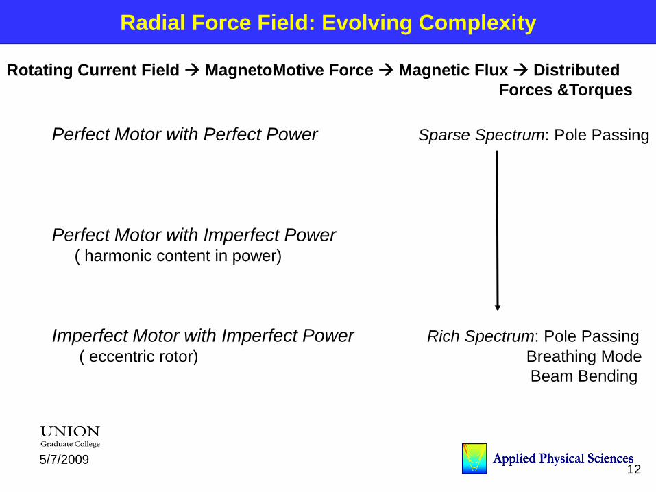
Radial Force Field: Evolving Complexity
Perfect Motor with Perfect Power Sparse Spectrum: Pole Passing
Perfect Motor with Imperfect Power( harmonic content in power)
Imperfect Motor with Imperfect Power Rich Spectrum: Pole Passing
( eccentric rotor) Breathing Mode
Beam Bending
Rotating Current Field MagnetoMotive Force Magnetic Flux Distributed
Forces &Torques

slide 13 135/7/2009
tprBtrB oairgap ×cos,, tprBtrB oairgap ×cos,,
Key
Relation
This is the “pole-passing” noise component. It exists in all AC machinery,
motors of any type and also in generators. It sets a lower limit on the minimum noise
an electric machine produces. It always occurs at twice the power line frequency (2E)
and this magnetic pressure wave always contains 2p pole-pairs (the order of the forcing function).
2
, ,cos
2
o
Radial
o
rr t
B p tP
2 2
, , cos 2 24 4
o o
Radial
o o
r rr t
B BP p t
2 1cos 1 cos 2 2
2p t p tNote:
Air gap flux density field of motor:
Radial stress function:
Perfect Motor – Perfect Power

slide 14 145/7/2009
Comparison of 60Hz flux density wave with
120 Hz pressure wave for a 4-Pole motor.
0 0.63 1.26 1.88 2.51 3.14 3.77 4.4 5.03 5.65 6.281
0.8
0.6
0.4
0.2
0
0.2
0.4
0.6
0.8
1AC Motor (60Hz, 4-Pole)
Air Gap Angle (rad.)
Magnetic Pressure Wave
Air gap flux density wave Ave. Magnetic Pressure
Note: There are 4 magnetic flux density poles in this graph
and 8 magnetic pressure poles (relative to the Ave. magnetic pressure value).
1
2
3
4
5
6
7
8
Magnetic
Pressure Poles
2
13
4
Magnetic
Flux Poles
Perfect Motor- Perfect Power
slide 15 155/7/2009
0 60 120 180 240 300 360 420 480 540 600 660 720 780 840 900 96050
42
34
26
18
10
2
6
14
22
30
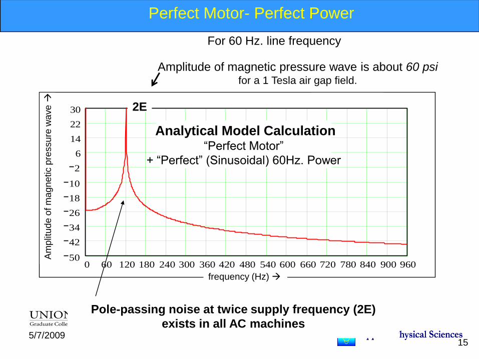
Frequency spectrum
of square of air gap B-field
Pole-passing noise at twice supply frequency (2E)
exists in all AC machines
Am
plit
ud
e o
f m
ag
ne
tic p
ressu
re w
ave
Analytical Model Calculation“Perfect Motor”
+ “Perfect” (Sinusoidal) 60Hz. Power
2E
frequency (Hz)
Amplitude of magnetic pressure wave is about 60 psifor a 1 Tesla air gap field.
For 60 Hz. line frequency
Perfect Motor- Perfect Power
slide 16 165/7/2009
DC PowerHigh Speed Solid-
State Switches
AC
Motor
Variable Voltage/
Variable Frequency
AC Power
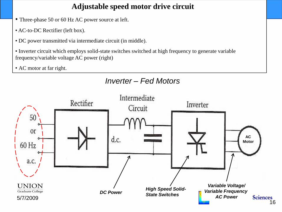
Adjustable speed motor drive circuit
• Three-phase 50 or 60 Hz AC power source at left.
• AC-to-DC Rectifier (left box).
• DC power transmitted via intermediate circuit (in middle).
• Inverter circuit which employs solid-state switches switched at high frequency to generate variable
frequency/variable voltage AC power (right)
• AC motor at far right.
Inverter – Fed Motors

slide 17 175/7/2009
Perfect Motor with Imperfect PowerTime harmonic currents from power supply
2cos cos
2
cos 2
2 2 41 cos 2 2 1 cos 2 2 2
4 4 cos 0
4
o n n
o
o n n
oo nn
o o o n n
o
mag
B p t B p t
B B p t
B Bp t p t
B B t
P
, cos cosairgap o n nB t B p t B p t
2
2
airgap
o
mag
BP
3 2 winding stPh n
n
k N IB
P
Consider just a single time harmonic current and the fundamental current. Both appear in the air gap field.
where
Using Maxwell stress
We arrive at
The two squared terms produce pole-passing noise;
one for the fundamental and one for the time harmonic.
The cross-product term contains two components;
• The first is a 2p-mode pressure wave with frequency -/+ n;
• The second is a zero-mode pressure wave with the opposite frequency n

slide 18 185/7/2009
Perfect Motor with Imperfect Power
Time harmonic currents from power supply
0 60 120 180 240 300 360 420 480 540 600 660 720 780 840 900 96050
42
34
26
18
10
2
6
14
22
30
Frequency spectrum of Square of air gap B-field
frequency (Hz)
Magnetic pressure vs frequency for AC motor
with 5th, 7th, 11th & 13th time harmonic currents.
10E
2E
4E6E
8E12E
14E
Ma
gn
etic p
ressu
re (
rela
tive
un
its)
Sum and difference terms

slide 19 195/7/2009
Imperfect Motor: Rotor Eccentricity

slide 20 205/7/2009
0 60 120 180 240 300 360 420 480 540 600 660 720 780 840 900 96050
42
34
26
18
10
2
6
14
22
30
Frequency spectrum of square of air gap B-field
frequency (Hz)
Magnetic pressure vs frequency for AC motor
with 5th, 7th, 11th & 13th time harmonic currents,
with rotor eccentricity.
10E
2E
4E
6E
8E12E
14E
Ma
gn
etic p
ressu
re (
rela
tive
un
its)
Imperfect Motor with Imperfect PowerTime harmonic currents from power supply & rotor eccentricity

slide 21 215/7/2009
Magnetic Torque
LRdtRPtRTorque
trBtrBtrP rad
2
00
2
0
tan0
tan
0
tan
]),,([),(
)],,(),,([1
),,( : distributed load
Motor Sources of Torque Ripple:
1. Cogging Effect : interaction between rotor magnetic flux & variable permeance of
air gap due to stator teeth & slot openings
2. Distortion of sinusoidal or trapezoidal distribution of magnetic flux in air gap
3. Differences between permeances of air gap along d (radial)- and q (tangential)-axes
Power Supply Sources of Torque Pulsation:
1. Current ripple resulting from PWM or rectifier harmonics
2. Phase current commutation

slide 22 225/7/2009
Influence of the switching frequency of an inverter
The phase voltage waveforms for PWM and Sinusoidal are:
0.03 0.035 0.04 0.045 0.05 0.055 0.06 0.065 0.07350
233.33
116.67
0
116.67
233.33
350
zero
Van t n
V
t n
sec
0.03 0.035 0.04 0.045 0.05 0.055 0.06 0.065 0.07350
233.33
116.67
0
116.67
233.33
350
zero
Vbn t n
V
t n
sec
0.03 0.035 0.04 0.045 0.05 0.055 0.06 0.065 0.07400
266.67
133.33
0
133.33
266.67
400
zero
VT 2 cos e t n
V
t n
sec
0.03 0.035 0.04 0.045 0.05 0.055 0.06 0.065 0.07400
266.67
133.33
0
133.33
266.67
400
zero
VT 2 cos e t n
2
3
V
t n
sec
Sinusoidal Phase Voltage for
Phase-AInverter Phase voltage
for Phase-A
Inverter Phase voltage
for Phase-B
Sinusoidal Phase Voltage for
Phase-B
4.9 4.91 4.92 4.93 4.94 4.95 4.96 4.97 4.98 4.99 550
40
30
20
10
0
10
20
30
40
50
60
70
80Phase-A Current vs. Time
time (seconds)
Phas
e C
urr
ent (A
)
Phase-A Current Waveform
Lots of current harmonics
30 Amp fundamental
@ frequency (50 Hz)
slide 23 235/7/2009
Influence of the switching frequency of an inverter
Figure 6: FFT of the phase current waveform shown in Figure 5. Switching frequency is
5,000 Hz. Supply frequency presented to the motor is 50 Hz. Graph produced by the APS
transient motor-motor drive model.
0 500 1000 1500 2000 2500 3000 3500 4000 4500 5000 5500 6000 6500 70000.01
0.1
1
10
100Phase A Current
Frequency (Hz)
Cu
rren
t
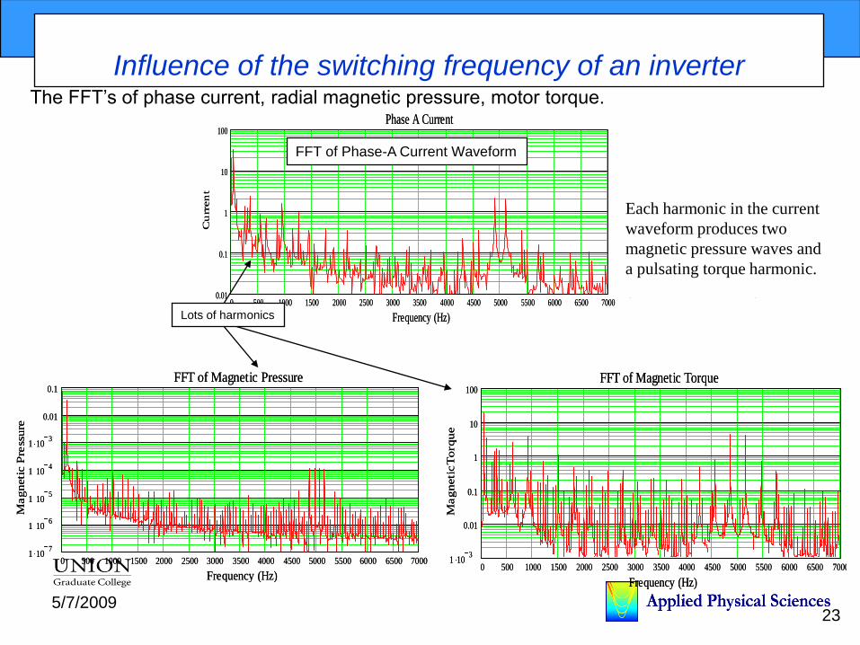
The FFT’s of phase current, radial magnetic pressure, motor torque.
FFT of Phase-A Current Waveform
Figure 7: FFT of the magnetic pressure produced by the motor model driven by the
voltage waveform shown in Figure 4. Switching frequency is 5,000 Hz. Supply frequency
presented to the motor is 50 Hz. Graph produced by the APS transient motor-motor drive
model.
0 500 1000 1500 2000 2500 3000 3500 4000 4500 5000 5500 6000 6500 70001 10
3
0.01
0.1
1
10
100FFT of Magnetic Torque
Frequency (Hz)
Magneti
cT
orq
ue
0 500 1000 1500 2000 2500 3000 3500 4000 4500 5000 5500 6000 6500 70001 10
7
1 106
1 105
1 104
1 103
0.01
0.1FFT of Magnetic Pressure
Frequency (Hz)
Magneti
c P
ress
ure
Figure 8: FFT of the magnetic torque produced by motor model when driven by the
voltage waveform shown in Figure 4. Switching frequency is 5,000 Hz. Supply frequency
presented to the motor is 50 Hz. Graph produced by the APS transient motor-motor drive
model.
0 500 1000 1500 2000 2500 3000 3500 4000 4500 5000 5500 6000 6500 70001 10
3
0.01
0.1
1
10
100FFT of Magnetic Torque
Frequency (Hz)
Magneti
cT
orq
ue
Lots of harmonics
Each harmonic in the current
waveform produces two
magnetic pressure waves and
a pulsating torque harmonic.
(ref. slides 20 & 29)

slide 24 245/7/2009
Structural Dynamics of Motor
Distributed EM Forces & Torques excite Stator & Rotor
Stator Modeled as Shell Structure
--- classical analytical methods
--- numerical methods (FEA, Impedance)
--- complexity of built up structure scattering mechanisms
Rotor Modeled as Beam
--- account for shaft, bearings, load
--- may need shell dynamics in vicinity of motor force field
Wide Bandwidth of Interest: Low High Frequency

slide 25 255/7/2009
Stator: Dynamics of Shell
0/]/)1[()12/()/(/)/1(/)/(
0/]/)1[(/)/1(/)/1(/]2/)1[(/]2/)1[(
0/]/)1[(/)/(/]2/)1[(/]2/)1[(/
2224222
2222222222
222222222
twEwhRwvRxuR
tvEwRvRxvxuR
tuExwRxvRuRxu
Governing Equations of Motion (e.g. Donnell)
)cos(
)sin(
)cos(
/8
1
/8
1
/8
1
neWw
eneVv
eneWw
Lx
i
i
tiLx
i
i
tiLx
i
i
i
i
i
:Separable Solutions
Low Frequency focus Separated Modes
slide 26 265/7/2009
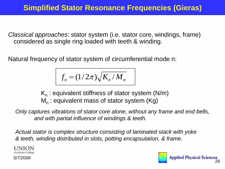
Simplified Stator Resonance Frequencies (Gieras)
Classical approaches: stator system (i.e. stator core, windings, frame) considered as single ring loaded with teeth & winding.
Natural frequency of stator system of circumferential mode n:
nnn MKf /)2/1(
Kn : equivalent stiffness of stator system (N/m)
Mn : equivalent mass of stator system (Kg)
Only captures vibrations of stator core alone, without any frame and end bells,
and with partial influence of windings & teeth.
Actual stator is complex structure consisting of laminated stack with yoke
& teeth, winding distributed in slots, potting encapsulation, & frame.

slide 27 275/7/2009
Simplified Stator: Breathing Mode
Breathing mode (n=0):
mdiciccmdccicc kkLhDkMMDLhEK 00 ;/)(4
hc : thickness
Mc : mass
Dc : mean diameter
c : mass density
ki : stacking factor
kmd : mass additions factor
ciwtmd MMMMk /)(1
Mt : mass of all stator teeth
Mw : mass of stator windings
Mc : mass of stator core cylinder
)/()/1(0 mdiccc kkEDf

slide 28 285/7/2009
Modal Approach to Shell Dynamics
Modal Equation of Motion
)]/cos(~)(..[);()cos()(),,(
)]/sin(~)(..[);()sin()(),,(
)]/sin(~)(..[);()cos()(),,(
]2[
1
3
1
1
3
1
1
3
1
2
LxmUxgexntqtxu
LxmVxgexntqtxv
LxmWxgexntqtxw
QqqqM
mnmnu
mnu
n m
mn
mnmnv
mnv
n m
mn
mnmnw
mnw
n m
mn
mnmnmnmnmnmnmnmn equation of motion
x
simply supported shell
Participation Factors: Umn/Wmn; Vmn/Wmn
Qmn : Generalized Forces due to Radial & Tangential Distributed Loads
slide 29 295/7/2009
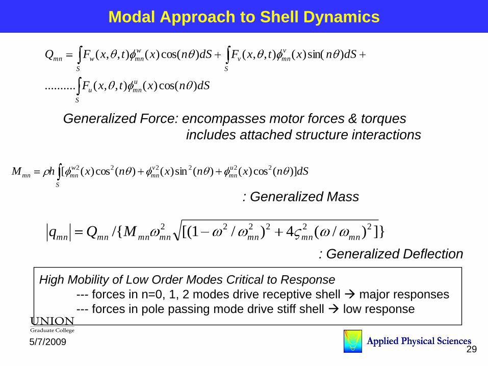
Modal Approach to Shell Dynamics
dSnxtxF
dSnxtxFdSnxtxFQ
u
mn
S
u
v
mn
S
v
w
mn
S
wmn
)cos()(),,(..........
)sin()(),,()cos()(),,(
dSnxnxnxhM u
mn
v
mn
S
w
mnmn )](cos)()(sin)()(cos)([ 222222
Generalized Force: encompasses motor forces & torques
includes attached structure interactions
: Generalized Mass
}])/(4)/1[(/{ 222222
mnmnmnmnmnmnmn MQq
: Generalized Deflection
High Mobility of Low Order Modes Critical to Response
--- forces in n=0, 1, 2 modes drive receptive shell major responses
--- forces in pole passing mode drive stiff shell low response

slide 30 305/7/2009
Drive Point Mobility: Radial Drive
101
102
103
-160
-150
-140
-130
-120
-110
-100
-90
-80
-70
Frequency, Hz
Mob
ility
, dB
re.
1 m
/N-s
Modal Drive Mobility Y22 - Drive Node 2
Yrr
stiffness
10-1
100
101
10-1
100
101
102
frequency ratio
non
dim
en
sio
nal
mob
ility
Nondimensional Mobility of Single Degree of Freedom System
stiffnesscontrolled
masscontrolled
mass
shell oscillator
Typical Drive Point Mobility

slide 31 315/7/2009
Sound Radiation Efficiency
Sound generated in medium by vibrations of structure.
Acoustic effects quantified by sound pressure & sound power.
Transfer function from structural vibration to acoustic response describes energy transfer mechanisms.
Sound radiation efficiency, : ]/[ 2
00 vSc
: sound power radiated from structure
S: area of radiating surface
0 : density of medium
c0 : speed of sound in medium
<v2> : spatial averaged mean square velocity over structure radiating surface
Relates radiated sound power to spatial averaged vibration level
slide 32 325/7/2009
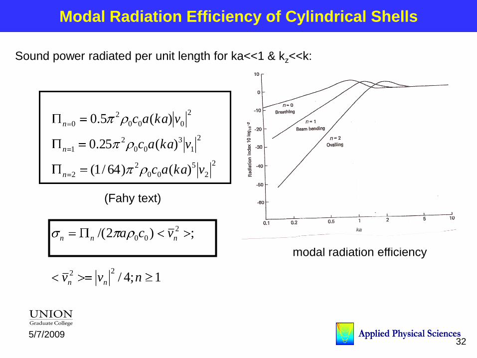
Modal Radiation Efficiency of Cylindrical Shells
Sound power radiated per unit length for ka<<1 & kz<<k:
1;4/
;)2/(
)()64/1(
)(25.0
)(5.0
22
2
00
2
2
5
00
2
2
2
1
3
00
2
1
2
000
2
0
nvv
vca
vkaac
vkaac
vkaac
nn
nnn
n
n
n
(Fahy text)
modal radiation efficiency
slide 33 335/7/2009
High Frequency Motor Acoustics
Forcing functions
motor drive switching interacting with motor
Structural Dynamics:
SEA &/or semi-infinite view of structure
Hybrid modeling with impedance & SEA methods
Radiation efficiency :
comparable modal efficiency at high wavenumbers
Stator Shell Structural Dynamics & Sound Radiation Change
-- Comparable Modal Structural Mobilities
-- Comparable Sound Radiation Efficiencies
Greater Focus on Pole Passing Motor Forces

slide 34 345/7/2009
Mechanical Sources of Noise & Vibration
Rotor Dynamics
--- classical rotating machinery sources
Bearings
--- classical discrete signals due to bearing defects
Cooling Fans
… blade passing tones
… turbulent flow broadband excitation
Classical approaches to Analysis & Quieting