Embed Size (px)
DESCRIPTION
Ac-heater System - Manual
Citation preview
A/C-HEATER SYSTEM - MANUALArticle Text
1996 Volkswagen GolfFor Volkswagen Technical Site
Copyright © 1998 Mitchell Repair Information Company, LLCThursday, August 19, 1999 11:25PM
ARTICLE BEGINNING
1995-96 MANUAL A/C-HEATER SYSTEMS Volkswagen
Cabrio, Golf, Golf III, GTI, Jetta & Jetta III
* PLEASE READ THIS FIRST *
WARNING: To avoid injury from accidental air bag deployment, read and carefully follow all SERVICE PRECAUTIONS and DISABLING & ACTIVATING AIR BAG SYSTEM procedures in the AIR BAG RESTRAINT SYSTEM article in the ACCESSORIES/SAFETY EQUIPMENT section.
CAUTION: When battery is disconnected, radio will go into anti-theft protection mode. Obtain radio anti-theft protection code from owner prior to servicing vehicle.
A/C SYSTEM SPECIFICATIONS
SPECIFICATIONSÄÄÄÄÄÄÄÄÄÄÄÄÄÄÄÄÄÄÄÄÄÄÄÄÄÄÄÄÄÄÄÄÄÄÄÄÄÄÄÄÄÄÄÄÄÄÄÄÄÄÄÄÄÄÄÄÄÄÄÄÄÄÄÄÄApplication Specification
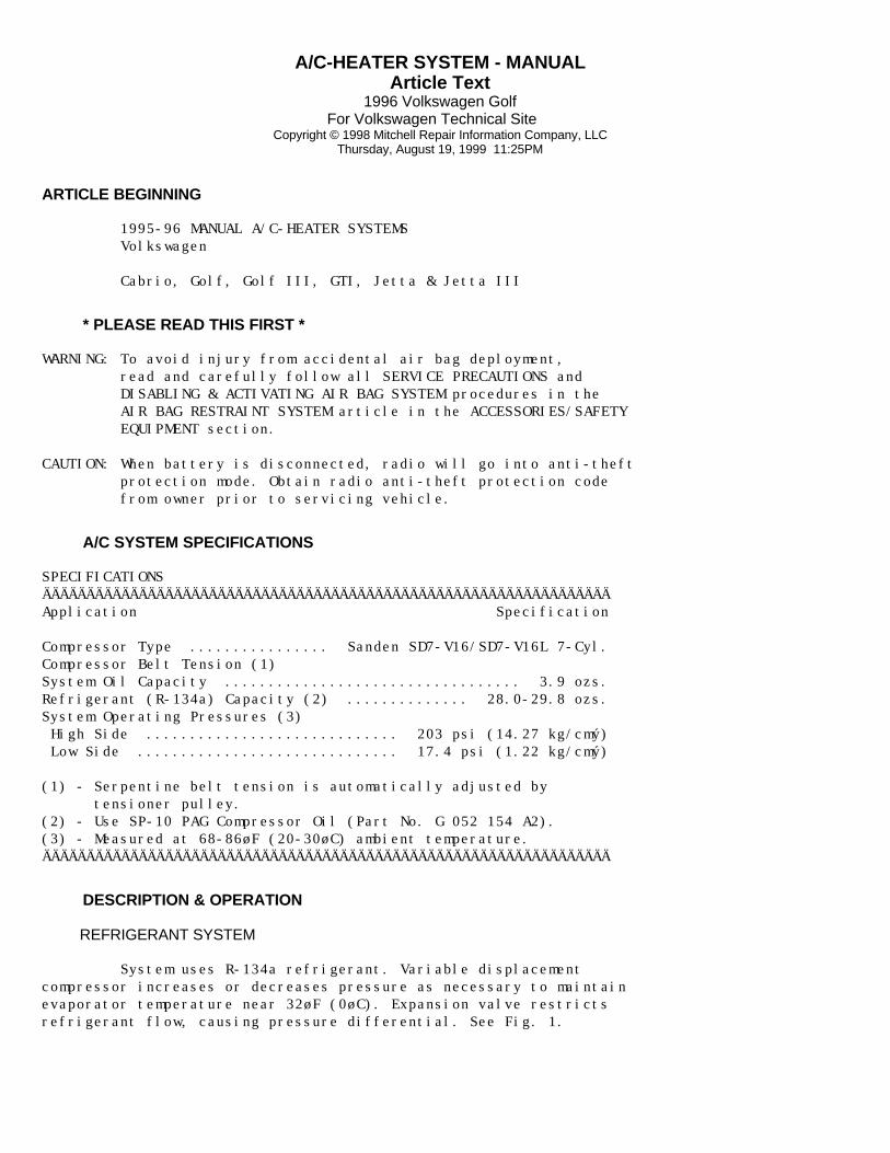
Compressor Type ................ Sanden SD7-V16/SD7-V16L 7-Cyl.Compressor Belt Tension (1)System Oil Capacity .................................. 3.9 ozs.Refrigerant (R-134a) Capacity (2) .............. 28.0-29.8 ozs.System Operating Pressures (3) High Side ............................. 203 psi (14.27 kg/cmý) Low Side .............................. 17.4 psi (1.22 kg/cmý)
(1) - Serpentine belt tension is automatically adjusted by tensioner pulley.(2) - Use SP-10 PAG Compressor Oil (Part No. G 052 154 A2).(3) - Measured at 68-86øF (20-30øC) ambient temperature.ÄÄÄÄÄÄÄÄÄÄÄÄÄÄÄÄÄÄÄÄÄÄÄÄÄÄÄÄÄÄÄÄÄÄÄÄÄÄÄÄÄÄÄÄÄÄÄÄÄÄÄÄÄÄÄÄÄÄÄÄÄÄÄÄÄ
DESCRIPTION & OPERATION
REFRIGERANT SYSTEM
System uses R-134a refrigerant. Variable displacementcompressor increases or decreases pressure as necessary to maintainevaporator temperature near 32øF (0øC). Expansion valve restrictsrefrigerant flow, causing pressure differential. See Fig. 1.
A/C-HEATER SYSTEM - MANUALArticle Text (p. 2)1996 Volkswagen Golf
For Volkswagen Technical Site Copyright © 1998 Mitchell Repair Information Company, LLC
Thursday, August 19, 1999 11:25PM
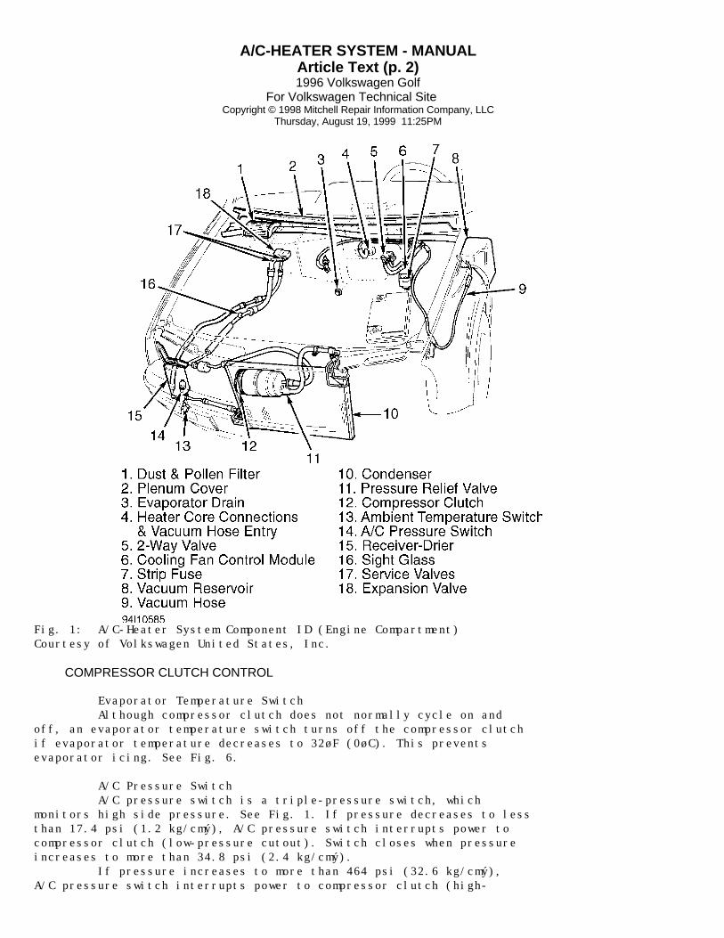
Fig. 1: A/C-Heater System Component ID (Engine Compartment)Courtesy of Volkswagen United States, Inc.
COMPRESSOR CLUTCH CONTROL
Evaporator Temperature Switch Although compressor clutch does not normally cycle on andoff, an evaporator temperature switch turns off the compressor clutchif evaporator temperature decreases to 32øF (0øC). This preventsevaporator icing. See Fig. 6.
A/C Pressure Switch A/C pressure switch is a triple-pressure switch, whichmonitors high side pressure. See Fig. 1. If pressure decreases to lessthan 17.4 psi (1.2 kg/cmý), A/C pressure switch interrupts power tocompressor clutch (low-pressure cutout). Switch closes when pressureincreases to more than 34.8 psi (2.4 kg/cmý). If pressure increases to more than 464 psi (32.6 kg/cmý),A/C pressure switch interrupts power to compressor clutch (high-

A/C-HEATER SYSTEM - MANUALArticle Text (p. 3)1996 Volkswagen Golf
For Volkswagen Technical Site Copyright © 1998 Mitchell Repair Information Company, LLC
Thursday, August 19, 1999 11:25PM
pressure cutout). Switch closes when pressure decreases to less than348 psi (24.5 kg/cmý). A/C pressure switch also controls cooling fan high speedoperation. If pressure increases to more than 232 psi (16.3 kg/cmý),switch contacts close, causing cooling fan to operate at high speed.When pressure decreases to less than 181 psi (12.7 kg/cmý), switchcontacts open.
Ambient Temperature Switch If ambient temperature decreases to less than 36øF (2øC),ambient temperature switch interrupts power to compressor clutch. Whenambient temperature increases to more than 45øF (7øC), ambienttemperature switch restores power to compressor clutch. See Fig. 1.
AIRFLOW CONTROL
Fresh/Recirculated Air Flap Fresh/recirculated air flap (door) above blower motorcontrols air entering ducting system. Flap is controlled by a vacuumservo. See Fig. 6. Vacuum supply to servo is controlled by a 2-wayvalve (electric solenoid), located between vacuum reservoir and vacuumservo. When voltage signal from A/C-heater control panel is applied tothe 2-way valve, the valve opens, allowing vacuum supply to vacuumservo.
Temperature Flap Temperature flap (door) diverts air through or around heatercore. Flap is controlled by a cable connected to the A/C-heatercontrol panel.
Central Flap Central flap (door) diverts air to face vents or to footwelland defrost vents (or a combination of all 3). Flap is controlled by acable connected to the A/C-heater control panel.
Footwell/Defrost Flap Footwell/defrost flap (door) diverts air to footwell ordefrost vents (or a combination of both). Flap is controlled by acable connected to the A/C-heater control panel.
ADJUSTMENTS
TEMPERATURE FLAP CABLE
Ensure cable is connected to A/C-heater control panel andpanel is installed. Remove cable sleeve retaining clip (cable sleeveis Blue). See Fig. 2. Disconnect cable from temperature flap lever.Adjust temperature control knob to maximum cold position. Connectcable to temperature flap lever. Push lever in direction of arrowuntil it stops. Hold lever in position, and install cable retainingclip.

A/C-HEATER SYSTEM - MANUALArticle Text (p. 4)1996 Volkswagen Golf
For Volkswagen Technical Site Copyright © 1998 Mitchell Repair Information Company, LLC
Thursday, August 19, 1999 11:25PM
Fig. 2: Adjusting Temperature Flap CableCourtesy of Volkswagen United States, Inc.
CENTRAL FLAP CABLE
Ensure cable is connected to A/C-heater control panel andpanel is installed. Remove cable sleeve retaining clip (cable sleeveis Black). See Fig. 3. Disconnect cable from central flap lever.Adjust airflow distribution knob to defrost position. Connect cable tocentral flap lever. Push lever in direction of arrow until it stops.Hold lever in position, and install cable retaining clip.
Fig. 3: Adjusting Central Flap CableCourtesy of Volkswagen United States, Inc.
FOOTWELL/DEFROST FLAP CABLE
Ensure cable is connected to A/C-heater control panel andpanel is installed. Remove cable sleeve retaining clip (cable sleeveis Black). See Fig. 4. Disconnect cable from footwell/defrost flaplever. Adjust airflow distribution knob to defrost position. Connect

A/C-HEATER SYSTEM - MANUALArticle Text (p. 5)1996 Volkswagen Golf
For Volkswagen Technical Site Copyright © 1998 Mitchell Repair Information Company, LLC
Thursday, August 19, 1999 11:25PM
cable to footwell/defrost flap lever. Push lever in direction of arrowuntil it stops. Hold lever in position and install cable retainingclip.
Fig. 4: Adjusting Footwell/Defrost Flap CableCourtesy of Volkswagen United States, Inc.
TESTING
WARNING: To avoid injury from accidental air bag deployment, read and carefully follow all SERVICE PRECAUTIONS and DISABLING & ACTIVATING AIR BAG SYSTEM procedures in the AIR BAG RESTRAINT SYSTEM article in the ACCESSORIES/SAFETY EQUIPMENT section.
A/C SYSTEM PERFORMANCE
1) Ensure no bubbles are present in sight glass. See Fig. 1.Connect manifold gauge set to service valves. Run engine at 1500 RPM.Set air distribution knob to face vent position. Set temperaturecontrol knob to full cold position. 2) Press A/C NORM button. Set blower motor on 2nd speed.System is okay if air temperature at center vent is less than 50øF(10øC) after one minute and system operating pressures are withinspecification. See SPECIFICATIONS table at beginning of article.
A/C PRESSURE SWITCH
NOTE: A/C pressure switch may be removed without discharging A/C system.
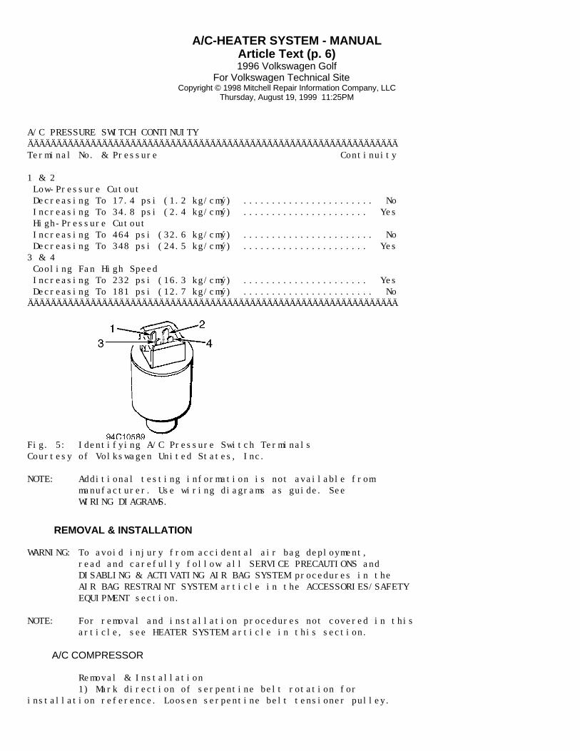
Connect manifold gauge set to service valves. Disconnect A/Cpressure switch connector. Check continuity between specified A/Cpressure switch terminals. See A/C PRESSURE SWITCH CONTINUITY table.See Fig. 5. Replace A/C pressure switch if continuity is not asspecified.
A/C-HEATER SYSTEM - MANUALArticle Text (p. 6)1996 Volkswagen Golf
For Volkswagen Technical Site Copyright © 1998 Mitchell Repair Information Company, LLC
Thursday, August 19, 1999 11:25PM
A/C PRESSURE SWITCH CONTINUITYÄÄÄÄÄÄÄÄÄÄÄÄÄÄÄÄÄÄÄÄÄÄÄÄÄÄÄÄÄÄÄÄÄÄÄÄÄÄÄÄÄÄÄÄÄÄÄÄÄÄÄÄÄÄÄÄÄÄÄÄÄÄÄÄÄTerminal No. & Pressure Continuity
1 & 2 Low-Pressure Cutout Decreasing To 17.4 psi (1.2 kg/cmý) ....................... No Increasing To 34.8 psi (2.4 kg/cmý) ...................... Yes High-Pressure Cutout Increasing To 464 psi (32.6 kg/cmý) ....................... No Decreasing To 348 psi (24.5 kg/cmý) ...................... Yes3 & 4 Cooling Fan High Speed Increasing To 232 psi (16.3 kg/cmý) ...................... Yes Decreasing To 181 psi (12.7 kg/cmý) ....................... NoÄÄÄÄÄÄÄÄÄÄÄÄÄÄÄÄÄÄÄÄÄÄÄÄÄÄÄÄÄÄÄÄÄÄÄÄÄÄÄÄÄÄÄÄÄÄÄÄÄÄÄÄÄÄÄÄÄÄÄÄÄÄÄÄÄ
Fig. 5: Identifying A/C Pressure Switch TerminalsCourtesy of Volkswagen United States, Inc.
NOTE: Additional testing information is not available from manufacturer. Use wiring diagrams as guide. See WIRING DIAGRAMS.
REMOVAL & INSTALLATION
WARNING: To avoid injury from accidental air bag deployment, read and carefully follow all SERVICE PRECAUTIONS and DISABLING & ACTIVATING AIR BAG SYSTEM procedures in the AIR BAG RESTRAINT SYSTEM article in the ACCESSORIES/SAFETY EQUIPMENT section.
NOTE: For removal and installation procedures not covered in this article, see HEATER SYSTEM article in this section.
A/C COMPRESSOR
Removal & Installation 1) Mark direction of serpentine belt rotation forinstallation reference. Loosen serpentine belt tensioner pulley.

A/C-HEATER SYSTEM - MANUALArticle Text (p. 7)1996 Volkswagen Golf
For Volkswagen Technical Site Copyright © 1998 Mitchell Repair Information Company, LLC
Thursday, August 19, 1999 11:25PM
Remove serpentine belt. 2) Discharge A/C system using approved refrigerantrecovery/recycling equipment. Disconnect refrigerant lines from A/Ccompressor. Remove A/C compressor bracket and/or A/C compressor, ifnecessary. To install, reverse removal procedure.
CONDENSER
Removal & Installation Discharge A/C system using approved refrigerantrecovery/recycling equipment. Remove front bumper. Remove bumper crosssupport. Disconnect refrigerant lines from condenser. Removecondenser. To install, reverse removal procedure.
EVAPORATOR HOUSING & EVAPORATOR
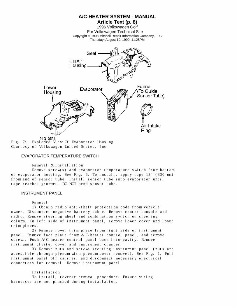
Removal & Installation Discharge A/C system using approved refrigerantrecovery/recycling equipment. Drain coolant. Remove instrument paneland support bracket. See INSTRUMENT PANEL. Remove evaporator housing.See Fig. 6. Disassemble evaporator housing. See Fig. 7.
Fig. 6: Exploded View Of A/C-Heater System ComponentsCourtesy of Volkswagen United States, Inc.
A/C-HEATER SYSTEM - MANUALArticle Text (p. 8)1996 Volkswagen Golf
For Volkswagen Technical Site Copyright © 1998 Mitchell Repair Information Company, LLC
Thursday, August 19, 1999 11:25PM
Fig. 7: Exploded View Of Evaporator HousingCourtesy of Volkswagen United States, Inc.
EVAPORATOR TEMPERATURE SWITCH
Removal & Installation Remove screw(s) and evaporator temperature switch from bottomof evaporator housing. See Fig. 6. To install, apply tape 13" (330 mm)from end of sensor tube. Install sensor tube into evaporator untiltape reaches grommet. DO NOT bend sensor tube.
INSTRUMENT PANEL
Removal 1) Obtain radio anti-theft protection code from vehicleowner. Disconnect negative battery cable. Remove center console andradio. Remove steering wheel and combination switch on steeringcolumn. On left side of instrument panel, remove lower cover and lowertrim pieces. 2) Remove lower trim piece from right side of instrumentpanel. Remove face plate from A/C-heater control panel, and removescrews. Push A/C-heater control panel back into cavity. Removeinstrument cluster cover and instrument cluster. 3) Remove nuts and screws securing instrument panel (nuts areaccessible through plenum with plenum cover removed). See Fig. 1. Pullinstrument panel off carrier, and disconnect necessary electricalconnectors for removal. Remove instrument panel.
Installation To install, reverse removal procedure. Ensure wiringharnesses are not pinched during installation.

A/C-HEATER SYSTEM - MANUALArticle Text (p. 9)1996 Volkswagen Golf
For Volkswagen Technical Site Copyright © 1998 Mitchell Repair Information Company, LLC
Thursday, August 19, 1999 11:25PM
VACUUM DIAGRAM
Fig. 8: Vacuum Diagram (Cabrio, Golf, Golf III & Jetta)Courtesy of Volkswagen United States, Inc.
WIRING DIAGRAMS

A/C-HEATER SYSTEM - MANUALArticle Text (p. 10)1996 Volkswagen Golf
For Volkswagen Technical Site Copyright © 1998 Mitchell Repair Information Company, LLC
Thursday, August 19, 1999 11:25PM
Fig. 9: Wiring Diagram (1995-96 Cabrio)

A/C-HEATER SYSTEM - MANUALArticle Text (p. 11)1996 Volkswagen Golf
For Volkswagen Technical Site Copyright © 1998 Mitchell Repair Information Company, LLC
Thursday, August 19, 1999 11:25PM
Fig. 10: Wiring Diagram (1995 Golf III & Jetta III 2.0L)
A/C-HEATER SYSTEM - MANUALArticle Text (p. 12)1996 Volkswagen Golf
For Volkswagen Technical Site Copyright © 1998 Mitchell Repair Information Company, LLC
Thursday, August 19, 1999 11:25PM
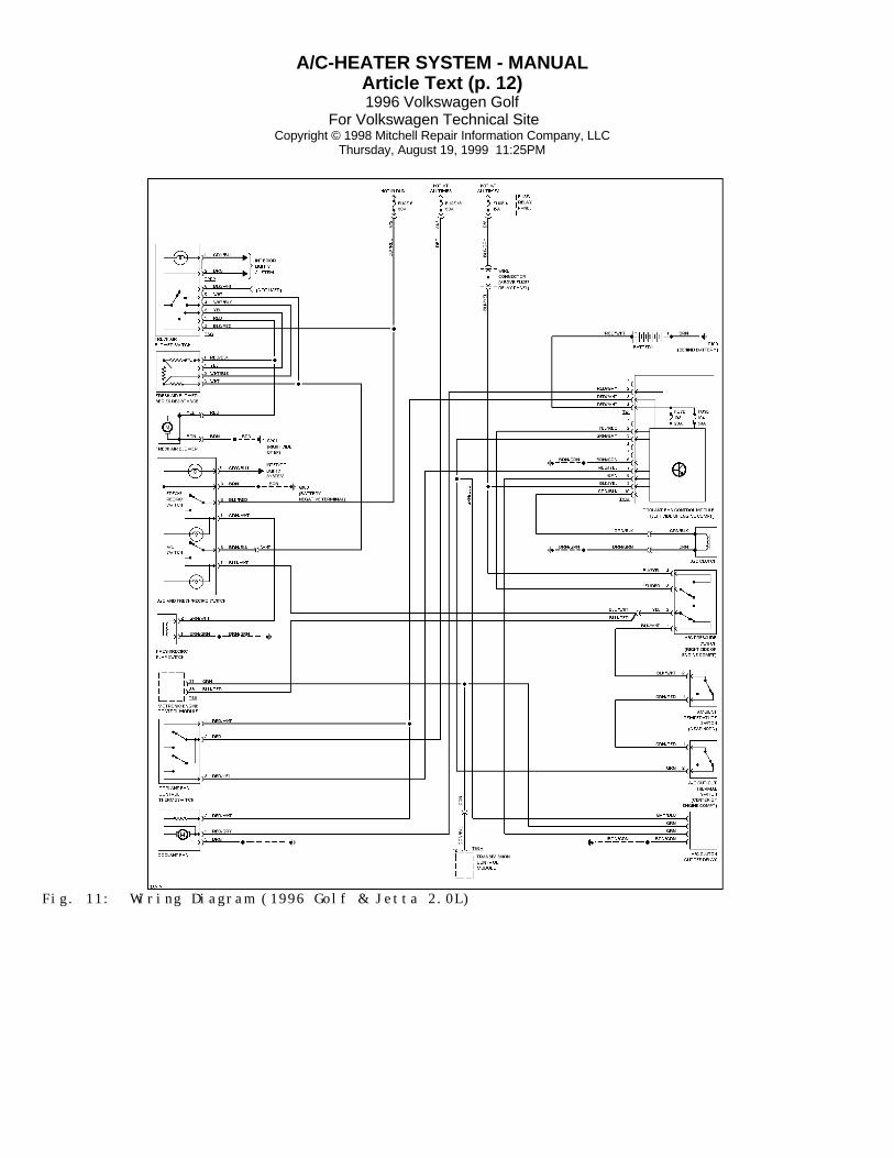
Fig. 11: Wiring Diagram (1996 Golf & Jetta 2.0L)

A/C-HEATER SYSTEM - MANUALArticle Text (p. 13)1996 Volkswagen Golf
For Volkswagen Technical Site Copyright © 1998 Mitchell Repair Information Company, LLC
Thursday, August 19, 1999 11:25PM
Fig. 12: Wiring Diagram (1995 -96 GTI & Jetta, Jetta III 2.8L)
END OF ARTICLE