Embed Size (px)
Citation preview

X4 AC Drive User’s Manual
TB Wood’s IncorporatedChambersburg, PA USA
Form 1428D

is a registered trademark of TB Wood’s, Inc. All other product names are trademarks of their respective
companies.
Copyright 2007, TB Wood’s, Inc. All rights reserved.
TB Wood’s Hassle-Free Warranty
The driving force at TB Wood’s is customer service, including dealing with unforeseen problems without creating new ones. TB Wood’s takes the extra step to ensure that any problem that occurs with its electronic products is dealt with swiftly and with no hassles to you. The Hassle-Free Warranty removes the “burden of guilt” and promises to quickly replace any failed product.
TB Wood’s Incorporated warrants the X4 Series AC drive to be free of defects in parts or workmanship for a period of three (3) years from the date of manufacture, or two (2) years from the date of installation, whichever comes first. If the TB Wood’s X4 Series AC drive fails for any reason, excluding physical abuse or repeated failure, within the warranty period, TB Wood’s will promptly replace the product. TB Wood’s Incorporated shall not in any event be liable for any incidental or consequential damages, secondary charges, expenses for installing or disconnecting, or losses to persons or property resulting from any failure of the product.

Summary of X4 Parameters
No. Parameter Name Options Default User Setting See Page
001 Model Number Model Dependent Read-only 50
002 Software Rev 0.00-99.99 Read-only 50
003 Rated Current 0.0-200.0 A Read-only 50
005 Serial No. 1 0-65535 Read-only 50
006 Serial No. 2 0-65535 Read-only 50
010 Last Fault text string Read-only 50
025 4th Fault text string Read-only 50
040 3rd Fault text string Read-only 50
055 2nd Fault text string Read-only 50
070 1st Fault text string Read-only 50
102 Output Freq 0.0-400.0 Hz Read-only 51
103 Output Voltage 0-600 V Read-only 51
104 Output Current 0.0-200.0 A Read-only 51
105 Drive Load -200.0-200.0% Read-only 51
106 Load Torque -200.0-200.0% Read-only 51
107 Drive Temp -20.0-200.0 °C Read-only 51
108 Total Run Time 0.0-6553.5 h Read-only 51
109 Power On Hours 0-65535 h Read-only 51
110 Stator Freq 0.0-400.0 Hz Read-only 51
111 DC Bus Voltage 0 - 1000 Vdc Read-only 51
115 Drive Power Out 0.0-200.0% Read-only 51
201 Input Mode text string Local Only 52
202 Rev Enable text string Forward 52
203 Stop Key Remote text string Coast 52
204 Ref Select text string Vin1 53
205 Vin1 Config text string 0-10V 53
206 Vin1 Offset 0.0% to 100.0 % 0.00% 53
207 Vin1 Span 10.0% to 200.0% 100.00% 54
208 Cin Config text string 0-20mA 50 54
209 Cin Offset 0.0% to 100.0% 0.0% 54
210 Cin Span 10.0% to 200.0% 100.0% 54
211 Vin2 Config text string 0-10V 54
212 Vin2 Offset 0.0% to 100.0 % 0.00% 54
213 Vin2 Span 10.0% to 200.0% 100.00% 54
214 Vin1 Filter Time 0 to 1000 ms 20 ms 54
215 Cin Filter Time 0 to 1000 ms 20 ms 55
216 Vin2 Filter Time 0 to 1000 ms 20 ms 55
217 Trim Ref Enable text string 0 55
218 Trim % Factor -100.0 - 100.0% 0.0% 55
301 Min Frequency 0.0 - Max Freq. 0.0 Hz 55
302 Max Frequency 20.0 - 400.0 Hz 60.0 Hz 55
303 Preset Freq 1 Min Freq-Max Freq 5.0 Hz 55
304 Preset Freq 2 Min Freq-Max Freq 10.0 Hz 55
305 Preset Freq 3 Min Freq-Max Freq 20.0 Hz 55
306 Preset Freq 4 Min Freq-Max Freq 30.0 Hz 55
307 Preset Freq 5 Min Freq-Max Freq 40.0 Hz 55
308 Preset Freq 6 Min Freq-Max Freq 50.0 Hz 55
309 Cut-Off Freq 0.0-5.0 Hz 0.0 Hz 56
401 Ramp Select text string ART-DI 56
402 Accel Time 1 0.1-3200.0 sec 5.0 sec 56
403 Decel Time 1 0.1-3200.0 sec 5.0 sec 56
= cannot change in RunBold type = Level 1 parameter
1428D-0607 - iii - © 2007 TB Wood’s All Rights Reserved

X4 AC Drive User’s Manual Summary of X4 Parameters
404 Accel Time 2 0.1-3200.0 sec 3.0 sec 56
405 Decel Time 2 0.1-3200.0 sec 3.0 sec 57
406 DC Inject Config text string DC at Stop 57
407 DC Inject Time 0.0-5.0 sec 0.2 sec 57
408 DC Inject Level 0.0% to 100.0% 50.0% 57
409 DC Inj Freq 0.0 to 20.0 Hz 0.0 Hz 57
410 DB Config text string Internal 58
414 S Ramp Rounding 1 - 100% 25% 58
490 App Macro text string Factory 40
491 Seq Appl text string Disabled 40
492 SIO Visible text string No 40
501 V/Hz Select text string Linear Fixed 59
502 Voltage Boost 0.0-50% 1.0% 59
503 V/Hz Knee Freq 25.0-400.0 Hz 60.0 Hz 59
504 Skip Freq Band 0.2-20.0 Hz 0.2 Hz 60
505 Skip Freq 1 Min Freq-Max Freq 0.0 Hz 60
506 Skip Freq 2 Min Freq-Max Freq 0.0 Hz 60
507 Skip Freq 3 Min Freq-Max Freq 0.0 Hz 60
508 Skip Freq 4 Min Freq-Max Freq 0.0 Hz 60
509 Rated Mtr Volt 100V-690V Model Dependent 60
510 Rated Mtr FLA 50% - 200% of ND Rating ND Rating 60
511 Rated Mtr RPM 0-24000 rpm 1750 rpm 60
512 Midpoint Freq 0.0 Hz-V/Hz Knee Freq 60.0 Hz 60
513 Midpoint Volt 0.0-100.0% 100.0% 60
514 Motor RS 0.0-655.35 Ohms Model Dependent 60
515 Power Factor 0.50-1.00 0.80 60
516 Slip Comp Enable text string No 61
517 Single Phase text string No 61
519 Find Mtr Data Not active / Motor RS Not active 61
520 Filter FStator 1 - 100 ms 8 ms 61
521 Start Field En Yes / No No 61
522 Filter Time Slip 10 - 1000 ms 100 ms 61
523 Id Percent 0 - 200% Read-only 62
524 Iq Percent 0 - 200% Read-only 62
525 Power Fail Config text string CTS No Msg 62
526 UV Ride-Thru En text string w/ LVT 62
600 Current Lim Sel 0-6 Fixed Lvls 63
601 Cur Lim Mtr Fwd 5%-150% 120% 63
602 Cur Lim Mtr Rev 5%-150% 120% 63
603 Cur Lim Reg Fwd 5%-150% 80% 63
604 Cur Lim Reg Rev 5%-150% 80% 63
605 Cur Lim Freq Min Freq-Max Freq 3.0 Hz 63
606 Ramp Time CL 0.1-3200.0 sec 1.0 sec 63
607 Cur Limit Minimum 0 - 50% 10% 63
608 Restart Number text string 0 64
609 Restart Delay 0-60 sec 60 sec 64
610 Timed OL Select text string Std Ind 60s 64
613 Max Regen Ramp 100 - 1000% 300% 64
700 Vmet Config text string Freq Out 65
701 Vmet Span 0.0-200.0% 100.0% 65
702 Imet Config text string Drive Load 65
703 Imet Span 0.0-200.0% 100.0% 65
704 Imet Offset 0.0-90.0-% 0.0% 65
No. Parameter Name Options Default User Setting See Page
1428D-0607 - iv - © 2007 TB Wood’s All Rights Reserved

X4 AC Drive User’s Manual Summary of X4 Parameters
705 Relay 1 Select text string Drv Fault 66
706 Relay 2 Select text string Drive Run 66
707 DO1 Select text string Drv Ready 66
708 DO2 Select text string At Speed 66
720 Active Logic text string Active High 66
721 D1 Configure text string Preset 1 67
722 D2 Configure text string Preset 2 67
723 D3 Configure text string Preset 3 67
724 D4 Configure text string Alt Ramp 67
725 D5 Configure text string Fault Reset 67
726 MOL Polarity text string NO Operate 67
727 MOL Configure text string MOL 68
801 Program Number 0-9999 0 68
802 Start Options text string LS Lockout 69
803 PWM Frequency 0.6-16.0 kHz 3.0 kHz 69
804 Display Mode text string Std Disply 69
805 Display Units(1) alphanumeric RPM:1 70
809 Display Scale 1-65535 1 70
810 Language text string English 70
811 Access Code 0-9999 0 70
812 Freq Ref Output text string 6FS 70
813 Speed Ratio 0.0-200.0% 100.0% 70
814 Display Status text string Drive load 71
816 Fly Catch Mode Sweep FWD / REV / F/R Sweep FWD 71
850 PI Configure text string No PI 71
851 PI Feedback text string Vin1 71
852 PI Prop Gain 0-2000 0 72
853 PI Int Gain 0-10000 0 72
854 PI Feed Gain 0-2000 1000 72
855 PI Error 1 0.00-100.00% Read-only 72
856 PI Error 2 0.00-100.00% Read-only 72
857 PI High Corr 0.00-100.00% 100.00% 72
858 PI Low Corr 0.00-100.00% 0.00% 72
900 SIO Protocol text string RTU N81 72
901 SIO Baud Rate text string 9600 72
902 Comm Drop # 1-247 1 72
903 SIO Timer 0.0-60.0 sec 1.0 sec 72
904 SIO Cntl Word text string 0x0000 73
905 Ext Ref Freq1 Min-Max Freq 0.0 Hz 73
906 Ext Ref Freq2 Min-Max Freq 0.0 Hz 73
908 Status Word text string Read-only 73
909 DI Status text string Read-only 73
910 Vin1 Status 0.00-100.00% Read-only 74
911 Cin Status 0.00-100.00% Read-only 74
912 Vin2 Status 0.00-100.00% Read-only 74
913 Output Status text string Read-only 74
914 Vmet Status 0.00-100.00% Read-only 74
915 Imet Status 0.00-100.00% Read-only 74
916 Infrared Baud n/a 9600 74
931 Seq Cntl 1 n/a 00000000000 74
932 Seq Cntl 2 n/a 00000000000 74
933 Seq Cntl 3 n/a 00000000000 74
934 Seq Cntl 4 n/a 00000000000 74
No. Parameter Name Options Default User Setting See Page
1428D-0607 - v - © 2007 TB Wood’s All Rights Reserved

X4 AC Drive User’s Manual Summary of X4 Parameters
935 Seq Cntl 5 n/a 00000000000 74
936 Seq Cntl 6 n/a 00000000000 74
937 Seq Cntl 7 n/a 00000000000 74
938 Seq Cntl 8 n/a 00000000000 74
939 Seq Cntl 9 n/a 00000000000 74
951 Seq Count 1 0-65535 0 75
952 Seq Count 2 0-65535 0 75
953 Seq Count 3 0-65535 0 75
954 Seq Count 4 0-65535 0 75
955 Seq Count 5 0-65535 0 75
956 Seq Count 6 0-65535 0 75
957 Seq Count 7 0-65535 0 75
958 Seq Count 8 0-65535 0 75
959 Seq Count 9 0-65535 0 75
No. Parameter Name Options Default User Setting See Page
1428D-0607 - vi - © 2007 TB Wood’s All Rights Reserved

TABLE OF CONTENTS
X4 User’s Manual
Summary of X4 Parameters . . . . . . . . . . . . . . . . . . . . . . . . . . . . . . . . . . . . . . . . . . . . . . . . . . . iii
Chapter 1: Introduction . . . . . . . . . . . . . . . . . . . . . . . . . . . . . . . . . . . . . . . . . . . . . . . . . . . . . . . 1
1.1 Product Overview . . . . . . . . . . . . . . . . . . . . . . . . . . . . . . . . . . . . . . . . . . . . . . . . . . . . . 11.2 Overview of This Manual . . . . . . . . . . . . . . . . . . . . . . . . . . . . . . . . . . . . . . . . . . . . . . 11.2 User’s Manual Publication History . . . . . . . . . . . . . . . . . . . . . . . . . . . . . . . . . . . . . . . 2
Chapter 2: Technical Characteristics . . . . . . . . . . . . . . . . . . . . . . . . . . . . . . . . . . . . . . . . . . . . 3
2.1 Interpreting Model Numbers . . . . . . . . . . . . . . . . . . . . . . . . . . . . . . . . . . . . . . . . . . . . 32.2 Power and Current Ratings . . . . . . . . . . . . . . . . . . . . . . . . . . . . . . . . . . . . . . . . . . . . . 42.3 Environmental Specifications . . . . . . . . . . . . . . . . . . . . . . . . . . . . . . . . . . . . . . . . . . . 52.4 Electrical Specifications . . . . . . . . . . . . . . . . . . . . . . . . . . . . . . . . . . . . . . . . . . . . . . . 62.5 Control Features Specifications . . . . . . . . . . . . . . . . . . . . . . . . . . . . . . . . . . . . . . . . . 62.6 Dimensions and Weights . . . . . . . . . . . . . . . . . . . . . . . . . . . . . . . . . . . . . . . . . . . . . . . 7
Chapter 3: Receiving and Installation . . . . . . . . . . . . . . . . . . . . . . . . . . . . . . . . . . . . . . . . . . 12
3.1 Preliminary Inspection . . . . . . . . . . . . . . . . . . . . . . . . . . . . . . . . . . . . . . . . . . . . . . . . 123.2 Installation Precautions . . . . . . . . . . . . . . . . . . . . . . . . . . . . . . . . . . . . . . . . . . . . . . . 123.3 Dissipation Requirements . . . . . . . . . . . . . . . . . . . . . . . . . . . . . . . . . . . . . . . . . . . . . 133.4 Cover Assembly and Torque Specifications . . . . . . . . . . . . . . . . . . . . . . . . . . . . . . . 143.5 Serial Number Label . . . . . . . . . . . . . . . . . . . . . . . . . . . . . . . . . . . . . . . . . . . . . . . . . 153.6 Conduit Usage . . . . . . . . . . . . . . . . . . . . . . . . . . . . . . . . . . . . . . . . . . . . . . . . . . . . . . 153.7 Condensation . . . . . . . . . . . . . . . . . . . . . . . . . . . . . . . . . . . . . . . . . . . . . . . . . . . . . . . 15
Chapter 4: Connections . . . . . . . . . . . . . . . . . . . . . . . . . . . . . . . . . . . . . . . . . . . . . . . . . . . . . . 16
4.1 Introduction . . . . . . . . . . . . . . . . . . . . . . . . . . . . . . . . . . . . . . . . . . . . . . . . . . . . . . . . 174.2 General Wiring Information . . . . . . . . . . . . . . . . . . . . . . . . . . . . . . . . . . . . . . . . . . . 17
4.2.1 Wiring Practices . . . . . . . . . . . . . . . . . . . . . . . . . . . . . . . . . . . . . . . . . . . . 174.2.2 Considerations for Power Wiring . . . . . . . . . . . . . . . . . . . . . . . . . . . . . . . 174.2.3 Considerations for Control Wiring . . . . . . . . . . . . . . . . . . . . . . . . . . . . . . 18
4.3 Input Line Requirements . . . . . . . . . . . . . . . . . . . . . . . . . . . . . . . . . . . . . . . . . . . . . . 184.3.1 Line Voltage . . . . . . . . . . . . . . . . . . . . . . . . . . . . . . . . . . . . . . . . . . . . . . . 184.3.2 Line Capacity . . . . . . . . . . . . . . . . . . . . . . . . . . . . . . . . . . . . . . . . . . . . . . 194.3.3 Phase Imbalance . . . . . . . . . . . . . . . . . . . . . . . . . . . . . . . . . . . . . . . . . . . . 194.3.4 Single-phase Operation . . . . . . . . . . . . . . . . . . . . . . . . . . . . . . . . . . . . . . . 194.3.5 Ground Fault Circuit Interrupters . . . . . . . . . . . . . . . . . . . . . . . . . . . . . . . 204.3.6 Motor Lead Length . . . . . . . . . . . . . . . . . . . . . . . . . . . . . . . . . . . . . . . . . . 204.3.7 Using Output Contactors . . . . . . . . . . . . . . . . . . . . . . . . . . . . . . . . . . . . . . 20
4.4 Terminals Found on the X4 Power Board . . . . . . . . . . . . . . . . . . . . . . . . . . . . . . . . . 204.4.1 Description of the Terminals . . . . . . . . . . . . . . . . . . . . . . . . . . . . . . . . . . . 204.4.2 Typical Power Connections . . . . . . . . . . . . . . . . . . . . . . . . . . . . . . . . . . . 21
1428D-0607 - vii - © 2007 TB Wood’s All Rights Reserved

X4 AC Drive User’s Manual Table of Contents
4.5 Dynamic Braking . . . . . . . . . . . . . . . . . . . . . . . . . . . . . . . . . . . . . . . . . . . . . . . . . . . . 234.6 Terminals Found on the X4 Control Board . . . . . . . . . . . . . . . . . . . . . . . . . . . . . . . . 25
4.6.1 Description of the Control Terminals . . . . . . . . . . . . . . . . . . . . . . . . . . . . 254.6.2 Typical Connection Diagrams for Digital Inputs . . . . . . . . . . . . . . . . . . . 284.6.3 Typical Connection Diagrams for Analog Inputs . . . . . . . . . . . . . . . . . . . 294.6.4 Typical Connection Diagrams for Analog Outputs . . . . . . . . . . . . . . . . . 29
Chapter 5: Keypad Operation and Programming . . . . . . . . . . . . . . . . . . . . . . . . . . . . . . . . 30
5.1 Introduction . . . . . . . . . . . . . . . . . . . . . . . . . . . . . . . . . . . . . . . . . . . . . . . . . . . . . . . . 305.2 Keypad Operation . . . . . . . . . . . . . . . . . . . . . . . . . . . . . . . . . . . . . . . . . . . . . . . . . . . 315.3 LCD Displays . . . . . . . . . . . . . . . . . . . . . . . . . . . . . . . . . . . . . . . . . . . . . . . . . . . . . . 33
5.3.1 Control . . . . . . . . . . . . . . . . . . . . . . . . . . . . . . . . . . . . . . . . . . . . . . . . . . . 335.3.2 X4 Keypad Status and Warning Messages . . . . . . . . . . . . . . . . . . . . . . . . 335.3.3 Rights . . . . . . . . . . . . . . . . . . . . . . . . . . . . . . . . . . . . . . . . . . . . . . . . . . . . 355.3.4 Other Data . . . . . . . . . . . . . . . . . . . . . . . . . . . . . . . . . . . . . . . . . . . . . . . . . 35
5.4 Keypad Display Window . . . . . . . . . . . . . . . . . . . . . . . . . . . . . . . . . . . . . . . . . . . . . . 355.5 Programming . . . . . . . . . . . . . . . . . . . . . . . . . . . . . . . . . . . . . . . . . . . . . . . . . . . . . . . 36
5.5.1 Accessing Parameters . . . . . . . . . . . . . . . . . . . . . . . . . . . . . . . . . . . . . . . . 365.5.2 Changing the Display Scroll Rate . . . . . . . . . . . . . . . . . . . . . . . . . . . . . . . 365.5.3 Programming Procedure . . . . . . . . . . . . . . . . . . . . . . . . . . . . . . . . . . . . . . 365.5.4 Restoring Factory Settings . . . . . . . . . . . . . . . . . . . . . . . . . . . . . . . . . . . . 375.5.5 Viewing Parameters That Have Changed . . . . . . . . . . . . . . . . . . . . . . . . . 375.5.6 Using Macro Mode . . . . . . . . . . . . . . . . . . . . . . . . . . . . . . . . . . . . . . . . . . 37
5.6 Measuring Stator Resistance (RS Measurement) . . . . . . . . . . . . . . . . . . . . . . . . . . . 375.6.1 Activating Automatic RS Measurement Using the Keypad . . . . . . . . . . 375.6.2 Activating Automatic RS Measurement via Serial Link (Modbus) . . . . . 38
Chapter 6: Using Macro Mode and Getting a Quick Start . . . . . . . . . . . . . . . . . . . . . . . . . 39
6.1 Entering Macro Mode . . . . . . . . . . . . . . . . . . . . . . . . . . . . . . . . . . . . . . . . . . . . . . . . 396.2 Description of Parameters Used in Macro Mode . . . . . . . . . . . . . . . . . . . . . . . . . . . . 406.3 Macro Mode Applications and Included Parameters . . . . . . . . . . . . . . . . . . . . . . . . . 426.4 Quick Start . . . . . . . . . . . . . . . . . . . . . . . . . . . . . . . . . . . . . . . . . . . . . . . . . . . . . . . . . 48
Chapter 7: X4 Parameters . . . . . . . . . . . . . . . . . . . . . . . . . . . . . . . . . . . . . . . . . . . . . . . . . . . . 49
7.1 Introduction . . . . . . . . . . . . . . . . . . . . . . . . . . . . . . . . . . . . . . . . . . . . . . . . . . . . . . . . 497.2 Level 1 Parameters . . . . . . . . . . . . . . . . . . . . . . . . . . . . . . . . . . . . . . . . . . . . . . . . . . . 497.3 Description of Parameters . . . . . . . . . . . . . . . . . . . . . . . . . . . . . . . . . . . . . . . . . . . . . 507.4 Using the X4 Program Sequencer . . . . . . . . . . . . . . . . . . . . . . . . . . . . . . . . . . . . . . . 75
7.4.1 Enabling the X4 Program Sequencer . . . . . . . . . . . . . . . . . . . . . . . . . . . . 757.4.2 Controlling the X4 Program Sequencer . . . . . . . . . . . . . . . . . . . . . . . . . . 757.4.3 Sequencer State Configuration Overview . . . . . . . . . . . . . . . . . . . . . . . . . 777.4.4 Sequencer Status Indicators . . . . . . . . . . . . . . . . . . . . . . . . . . . . . . . . . . . 807.4.5 Sample Sequencer Program . . . . . . . . . . . . . . . . . . . . . . . . . . . . . . . . . . . 80
Chapter 8: Troubleshooting . . . . . . . . . . . . . . . . . . . . . . . . . . . . . . . . . . . . . . . . . . . . . . . . . . 83
1428D-0607 - viii - © 2007 TB Wood’s All Rights Reserved

Chapter 1: Introduction
1.1 Product Overview
Although the X4 AC drive is small in size, it is big on performance. It is an economical yet powerful solution for many industrial applications. It features remote communications capability (using Modbus® protocol), a keypad for easy configuration, and standard NEMA 4X / IP66 and NEMA 12 / IP54 enclosures that eliminate the need for mounting in a separate enclosure.
The X4 product family includes a wide variety of models to suit almost any input voltage requirement. An ‘x’ in the following table indicates what models are currently available. Refer to Chapter 2 for help in interpreting model numbers.
1.2 Overview of This Manual
This manual contains specifications, receiving and installation instructions, configuration, description of operation, and troubleshooting procedures for X4 AC drive devices.
HorsepowerInput Voltage
115 Vac 1 Phase
230 Vac3 Phase
460 Vac3 Phase
575 Vac3 Phase
1 x x x x
2 x x x
3 x x x
5 x x x
7.5 x x x
10 x x x
15 x x x
20 x x x
25 x x x
30 x x x
40 x x
50 x x
60 x x
75 x x
100 x x
125 x x
150 x x
200 x x
1428D-0607 - 1 - © 2007 TB Wood’s All Rights Reserved

X4 AC Drive User’s Manual Chapter 1: Introduction
1.3 User’s Manual Publication History
Date Form Number Nature of Change
June 2005 1428 First release
March 2006 1428B
Minor corrections throughout manual.Clarification of technical information and specifications.Added X4 models for Frame Size 2.Reformatted to larger page-size document; separated appendices from manual to be available on the TB Wood’s web site (www.tbwoods.com).
August 2006 1428CMinor corrections and enhancements throughout manual.Added 40 and 50 HP models.
June 2007 1428DAdded 60-200 HP models, new parameters.Minor corrections and reformatting throughout manual.
1428D-0607 - 2 - © 2007 TB Wood’s All Rights Reserved
Chapter 2: Technical Characteristics
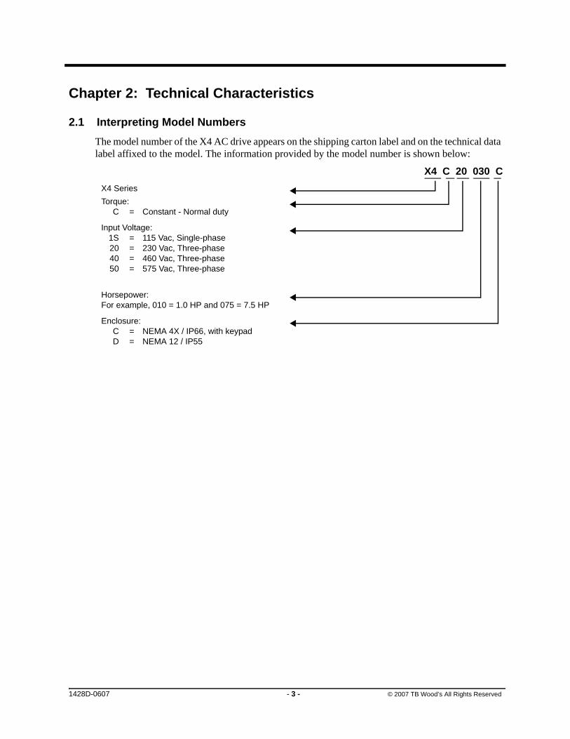
2.1 Interpreting Model Numbers
The model number of the X4 AC drive appears on the shipping carton label and on the technical data label affixed to the model. The information provided by the model number is shown below:
X4 C 20 030 C
X4 Series
Torque:C = Constant - Normal duty
Input Voltage:1S = 115 Vac, Single-phase20 = 230 Vac, Three-phase40 = 460 Vac, Three-phase50 = 575 Vac, Three-phase
Horsepower:For example, 010 = 1.0 HP and 075 = 7.5 HP
Enclosure:C = NEMA 4X / IP66, with keypadD = NEMA 12 / IP55
1428D-0607 - 3 - © 2007 TB Wood’s All Rights Reserved

X4 AC Drive User’s Manual Chapter 2: Technical Characteristics
2.2 Power and Current Ratings
115 Vac Ratings
Model number
Normal Duty Input current (A) Output current (A) Heavy Duty Input current (A) Output current (A)
HP kW - 115 Vac - 230 Vac HP kW - 115 Vac - 230 Vac
X4C1S010C 1 0.75 - 15 - 4.2 0.5 0.37 - 11 0 2.2
230 Vac Ratings
Model number
Normal Duty Input current (A) Output current (A) Heavy Duty Input current (A) Output current (A)
HP kW 200 Vac 230 Vac 200 Vac 230 Vac HP kW 200 Vac 230 Vac 200 Vac 230 Vac
X4C20010C 1 0.75 5.6 4.8 4.8 4.2 0.5 0.37 2.9 2.5 2.5 2.2
X4C20020C 2 1.5 9 7.8 7.8 6.8 1 0.75 5.6 4.8 4.8 4.2
X4C20030C 3 2.2 12.7 11 11 9.6 2 1.5 9 7.8 7.8 6.8
X4C20050C 5 4 20.2 17.5 17.5 15.2 3 2.2 12.7 11 11 9.6
X4C20075C 7.5 5.5 29.2 25.3 25.3 22 5 4 20.2 17.5 17.5 15.2
X4C20100C 10 7.5 37.2 32.2 37.2 28 7.5 5.5 29.2 25.3 25.3 22
X4C20150C 15 11 52.1 46.4 48.3 42 10 7.5 37.2 32.2 37.2 28
X4C20200C 20 15 68.3 57.4 62.1 54 15 11 52.1 46.4 48.3 42
X4C20250C 25 18.5 82.3 73.8 78.2 68 20 15 68.3 57.4 62.1 54
X4C20300C 30 18.5 96 84 92 80 25 18.5 82.3 73.8 78.2 68
NOTE: All 230 Vac models can be operated at single-phase, with 50% derating
460 Vac Ratings
Model number
Normal Duty Input current (A) Output current (A) Heavy Duty Input current (A) Output current (A)
HP kW 380 Vac 460 Vac 380 Vac 460 Vac HP kW 380 Vac 460 Vac 380 Vac 460 Vac
X4C40010C 1 0.75 3 2.4 2.4 2.1 0.5 0.37 1.6 1.3 1.3 1.1
X4C40020C 2 1.5 5.2 3.9 3.8 3.4 1 0.75 3 2.4 2.4 2.1
X4C40030C 3 2.2 7.2 5.6 5.1 4.8 2 1.5 5.2 3.9 3.8 3.4
X4C40050C 5 4 12 8.8 8.9 7.6 3 2.2 7.2 5.6 5.1 4.8
X4C40075C 7.5 5.5 15 12.8 12 11 5 4 12 8.8 8.9 7.6
X4C40100C 10 7.5 19.7 16.3 15.6 14 7.5 5.5 15 12.8 12 11
X4C40150C 15 11 30.9 25.8 23 21 10 7.5 19.7 16.3 15.6 14
X4C40200C 20 15 40 33.3 31 27 15 11 30.9 25.8 23 21
X4C40250C 25 18 46.3 40 37 34 20 15 40 33.3 31 27
X4C40300C 30 22 57.5 47.8 43 40 25 18 46.3 40 37 34
X4C40400C 40 30 73.2 62.4 61 52 30 22 57.5 47.8 43 40
X4C40500C 50 37 82 78 71 65 40 30 73.2 62.4 61 52
X4C40600C 60 45 94 80 86 77 50 37 82 78 71 65
X4C40750C 75 55 114 99 105 96 60 45 94 80 86 77
X4C41000C 100 75 149 129 140 124 75 55 114 99 105 96
X4C41250C 125 90 168 156 168 156 100 75 140 124 140 124
X4C41500C 150 110 205 180 205 180 125 90 168 156 168 156
X4C42000C 200 132 240 240 240 240 150 110 205 180 205 180
1428D-0607 - 4 - © 2007 TB Wood’s All Rights Reserved

X4 AC Drive User’s Manual Chapter 2: Technical Characteristics
2.3 Environmental Specifications
575 Vac Ratings
Model number
Normal Duty Input current (A) Output current (A) Heavy Duty Input current (A) Output current (A)
HP kW - 575 Vac - 575 Vac HP kW - 575 Vac - 575 Vac
X4C50010C 1 0.75 - 2.0 - 1.7 0.5 0.37 - 1.2 - 0.9
X4C50020C 2 1.5 - 3.6 - 2.7 1 0.75 - 2.0 - 1.7
X4C50030C 3 2.2 - 5.0 - 3.9 2 1.5 - 3.6 - 2.7
X4C50050C 5 4 - 7.6 - 6.1 3 2.2 - 5.0 - 3.9
X4C50075C 7.5 5.5 - 10.4 - 9.0 5 4 - 7.6 - 6.1
X4C50100C 10 7.5 - 14.1 - 11.0 7.5 5.5 - 10.4 - 9.0
X4C50150C 15 11 - 23 - 17 10 7.5 - 14.1 - 11
X4C50200C 20 15 - 31 - 22 15 11 - 23 - 17
X4C50250C 25 18 - 37 - 27 20 15 - 31 - 22
X4C50300C 30 22 - 39.5 - 32 25 18 - 37 - 27
X4C50400C 40 30 - 49 - 41 30 22 - 39.5 - 32
X4C50500C 50 37 - 58 - 52 40 30 - 49 - 41
X4C50600C 60 45 - 68 - 62 50 37 - 58 - 52
X4C50750C 75 55 - 82 - 77 60 45 - 68 - 62
X4C51000C 100 75 - 107 - 99 75 55 - 82 - 77
X4C51250C 125 90 - 125 - 125 100 75 - 99 - 99
X4C51500C 150 110 - 144 - 144 125 90 - 125 - 125
X4C52000C 200 132 - 192 - 192 150 110 - 144 - 144
Operating temperature
For 2003, 2005, 5005, 2030, 4030, and 5030 models:–10 °C to +35 °C (14 °F to 95 °F) For all other models:–10 °C to +40 °C (14 °F to 104 °F)
Storage temperature –20 °C to +65 °C (-4 °F to 149 °F)
Humidity 0% to 95% non-condensing
Altitude 1000 m (3300 ft) without derating
Maximum vibration per EN50178 (1g @ 57-150 Hz)
Acoustic noise 80 dba sound power at 1 m (3 ft), maximum
Cooling1 to 5 HP models: Natural convection7.5 to 200.0 HP models: Forced airNote: 575Vac 5 HP model has a fan.
1428D-0607 - 5 - © 2007 TB Wood’s All Rights Reserved
X4 AC Drive User’s Manual Chapter 2: Technical Characteristics
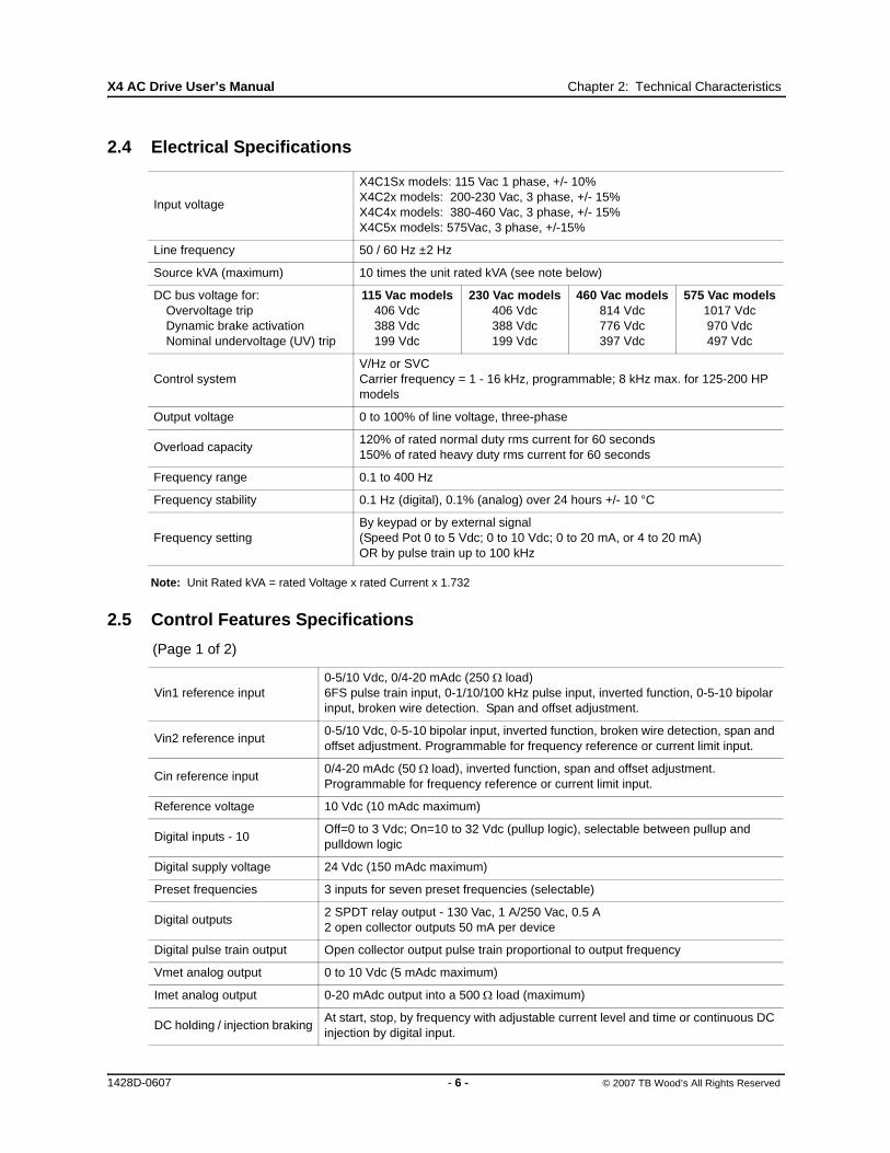
2.4 Electrical Specifications
Note: Unit Rated kVA = rated Voltage x rated Current x 1.732
2.5 Control Features Specifications
Input voltage
X4C1Sx models: 115 Vac 1 phase, +/- 10%X4C2x models: 200-230 Vac, 3 phase, +/- 15%X4C4x models: 380-460 Vac, 3 phase, +/- 15%X4C5x models: 575Vac, 3 phase, +/-15%
Line frequency 50 / 60 Hz ±2 Hz
Source kVA (maximum) 10 times the unit rated kVA (see note below)
DC bus voltage for:Overvoltage trip Dynamic brake activation Nominal undervoltage (UV) trip
115 Vac models406 Vdc388 Vdc199 Vdc
230 Vac models406 Vdc388 Vdc199 Vdc
460 Vac models814 Vdc776 Vdc397 Vdc
575 Vac models1017 Vdc970 Vdc497 Vdc
Control systemV/Hz or SVCCarrier frequency = 1 - 16 kHz, programmable; 8 kHz max. for 125-200 HP models
Output voltage 0 to 100% of line voltage, three-phase
Overload capacity120% of rated normal duty rms current for 60 seconds150% of rated heavy duty rms current for 60 seconds
Frequency range 0.1 to 400 Hz
Frequency stability 0.1 Hz (digital), 0.1% (analog) over 24 hours +/- 10 °C
Frequency settingBy keypad or by external signal (Speed Pot 0 to 5 Vdc; 0 to 10 Vdc; 0 to 20 mA, or 4 to 20 mA)OR by pulse train up to 100 kHz
(Page 1 of 2)
Vin1 reference input0-5/10 Vdc, 0/4-20 mAdc (250 Ω load)6FS pulse train input, 0-1/10/100 kHz pulse input, inverted function, 0-5-10 bipolar input, broken wire detection. Span and offset adjustment.
Vin2 reference input0-5/10 Vdc, 0-5-10 bipolar input, inverted function, broken wire detection, span and offset adjustment. Programmable for frequency reference or current limit input.
Cin reference input0/4-20 mAdc (50 Ω load), inverted function, span and offset adjustment. Programmable for frequency reference or current limit input.
Reference voltage 10 Vdc (10 mAdc maximum)
Digital inputs - 10Off=0 to 3 Vdc; On=10 to 32 Vdc (pullup logic), selectable between pullup and pulldown logic
Digital supply voltage 24 Vdc (150 mAdc maximum)
Preset frequencies 3 inputs for seven preset frequencies (selectable)
Digital outputs2 SPDT relay output - 130 Vac, 1 A/250 Vac, 0.5 A2 open collector outputs 50 mA per device
Digital pulse train output Open collector output pulse train proportional to output frequency
Vmet analog output 0 to 10 Vdc (5 mAdc maximum)
Imet analog output 0-20 mAdc output into a 500 Ω load (maximum)
DC holding / injection brakingAt start, stop, by frequency with adjustable current level and time or continuous DC injection by digital input.
1428D-0607 - 6 - © 2007 TB Wood’s All Rights Reserved

X4 AC Drive User’s Manual Chapter 2: Technical Characteristics
2.6 Dimensions and Weights
Table 2-1 lists dimensions and weights for the X4 frame size 0, 1, 2, and 3 models. Dimensions and weights for the X4 frame size 4 and 5 models are shown in Table 2-2 on page 8.
See Figures 2-1, 2-2, 2-3, 2-4, 2-5, and 2-6 on pages 8 - 11 for locations of dimensions. Dimensions A through Q are in inches / millimeters (in/mm). Weight is in pounds / kilograms (lb/kg).
Current limit Four quadrant adjustable from 5 to 150%
Speed ramps Primary and alternate adjustable from 0.1 to 3200.0 seconds
Voltage boost Fixed boost adjustable from 0 to 50%, or auto boost in Vector mode
Voltage characteristic (V/Hz) Linear, pump, fan or 2-piece linear
Timed overloadAdjustable inverse time trip (shear pin, 30 sec, 60 sec, 5 min), standard or inverter-duty motors
Protective featuresOvercurrent, overvoltage fault, ground fault, short circuit, dynamic brake overload, drive temperature, power wiring fault, drive timed overload, input voltage quality, overvoltage ridethrough
Program Sequence Logic Controller (PSLC)
9-step PLC type functionality that can control speed, direction, and ramps based on time, analog input, digital input, or pulse input.
Serial communications Modbus Standard: RTU or ASCII
Table 2-1: Dimensions and Weights for Frame Sizes 0 - 3
Frame 0 1 2 3
Voltage115 Vac
230 Vac
460 Vac
230 Vac
460 Vac
575 Vac
230 Vac
460 Vac
575 Vac
230 Vac
460 Vac
575 Vac
Horsepower 1 1-3 5-7.5 5-10 1-10 10-15 15-30 15-30 20-25 40-50 40-50
Dimensionsin (mm)
(See X4 diagrams on
pages 8 through 10)
A 9.47 (241) 12.01 (306) 17.38 (442) 20.19 (513)
B 6.50 (165) 8.72 (221) 10.75 (273) 11.25 (286)
C 6.08 (155) 6.51 (166) 7.91 (201) 11.73 (314)
D 8.45 (215) 11.03 (280) 16.50 (419) 19.25 (489)
E 5.69 (145) 7.88 (200) 9.76 (248) 7.88 (200)
F 0.28 (7.11) 0.28 (7.11) 0.41 (10) 0.28 (7.11)
G 3.84 (98) 4.05 (103) 4.72 (120) 7.78 (198)
H 2.77 (70) N/A N/A N/A
J 1.93 (49) 2.31 (59) 2.88 (73) 0.65 (13)
K 2.85 (72) 3.94 (100) 4.84 (123) 2.29 (58)
L 3.75 (95) 5.56 (1.41) 6.88 (175) 3.95 (100)
M 0.88 (22) 0.88 (22) 1.38 (35) 1.69 (44)
N N/A N/A 1.13 (29) 0.88 (22)
P N/A N/A N/A 5.60 (142)
Q N/A N/A N/A 7.24 (184)
Weight lb (kg)
8.5 (3.85) 14.0 (6.35) 29.5 (13.38) 50.0 (22.68)
(Page 2 of 2)
1428D-0607 - 7 - © 2007 TB Wood’s All Rights Reserved

X4 AC Drive User’s Manual Chapter 2: Technical Characteristics
Figure 2-1: X4 Frame Size 0 Models
Table 2-2: Dimensions and Weights for Frame Sizes 4-5
Frame 4 5
Voltage 460 Vac 575 Vac 460 Vac 575 Vac
Horsepower 60-100 60-100 125-200 125-200
Dimensionsin (mm)
(See X4 diagrams on
pages 10 - 11)
A 29.35 (745) 29.35 (745) 50.77 (1290) 51.02 (1296)
B 12.84 (326) 12.84 (326) 16.31 (414) 16.31 (414)
C 13.80 (351) 13.80 (351) 16.88 (429) 16.88 (429)
D 28.00 (711) 28.00 (711) 45.77 (1163) 45.77 (1163)
E 7.88 (200) 7.88 (200) 7.65 (194) 7.65 (194)
F 0.42 (11) 0.42 (11) 0.42 (11) 0.42 (11)
G 8.63 (219) 8.63 (219) 12.57 (319) 12.57 (319)
H 8.26 (210) 8.26 (210) 11.10 (282) 11.10 (282)
J 0.53 (14) 0.53 (14) 0.20 (5) 0.20 (5)
K 2.69 (68) 2.69 (68) 2.32 (59) 2.32 (59)
L 3.94 (100) 3.94 (100) 3.82 (97) 3.82 (97)
M 2.44 (62) 2.44 (62) 2.94 (75) 2.94 (75)
N 0.88 (22) 0.88 (22) 0.88 (22) 0.88 (22)
P 5.19 (132) 5.19 (132) 5.32 (135) 5.32 (135)
Q 7.35 (187) 7.35 (187) 7.45 (189) 7.45 (189)
R 10.23 (260) 10.23 (260) N/A N/A
S 1.94 (49) 1.94 (49) 1.86 (47) 1.86 (47)
Weight lb (kg)
95.0 (43.10)) 305.0 (138.35)
A
B
D
E
F
J
K
L
C
G
H
M
1428D-0607 - 8 - © 2007 TB Wood’s All Rights Reserved

X4 AC Drive User’s Manual Chapter 2: Technical Characteristics
Figure 2-2: X4 Frame Size 1 Models
Figure 2-3: X4 Frame Size 2 Models
C
G
J
K
L
M
NB F
AD
E
1428D-0607 - 9 - © 2007 TB Wood’s All Rights Reserved
X4 AC Drive User’s Manual Chapter 2: Technical Characteristics
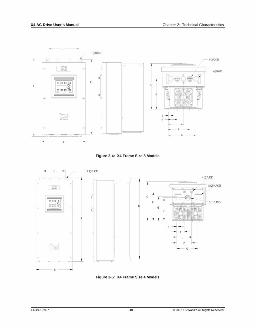
Figure 2-4: X4 Frame Size 3 Models
Figure 2-5: X4 Frame Size 4 Models
D
A
F (8) PLACES
B
E
C
G
J
K
L
P
Q
N (3) PLACES
M (2) PLACES
B
A
E F (8) PLACES
D
C
GH
R
M(2) PLACES
S (1) PLACES
N (2) PLACES
J
K
L
P
Q
1428D-0607 - 10 - © 2007 TB Wood’s All Rights Reserved

X4 AC Drive User’s Manual Chapter 2: Technical Characteristics
Figure 2-6: X4 Frame Size 5 Models
B
A
E F (8) PLACES
D
C
HG
J
K
L
PQ
M (2) PLACES
S (1) PLACE
N(2) PLACES
1428D-0607 - 11 - © 2007 TB Wood’s All Rights Reserved

Chapter 3: Receiving and Installation
3.1 Preliminary Inspection
Before storing or installing the X4 AC drive, thoroughly inspect the device for possible shipping damage. Upon receipt:
1. Remove the drive from its package and inspect exterior for shipping damage. If damage is apparent, notify the shipping agent and your sales representative.
2. Remove the cover and inspect the drive for any apparent damage or foreign objects. (See Figure 3-1 on page 14 for locations of cover screws.) Ensure that all mounting hardware and terminal connection hardware is properly seated, securely fastened, and undamaged.
3. Read the technical data label affixed to the drive and ensure that the correct horsepower and input voltage for the application has been purchased.
4. If you will be storing the drive after receipt, place it in its original packaging and store it in a clean, dry place free from direct sunlight or corrosive fumes, where the ambient temperature is not less than -20 °C (-4 °F) or greater than +65 °C (+149 °F).
3.2 Installation Precautions
Improper installation of the X4 AC drive will greatly reduce its life. Be sure to observe the following precautions when selecting a mounting location. Failure to observe these precautions may void the warranty! See the inside front cover of this manual for more information about the warranty.
• Do not install the drive in a place subjected to high temperature, high humidity, excessive vibration, corrosive gases or liquids, or airborne dust or metallic particles. See Chapter 2 for temperature, humidity, and maximum vibration limits.
• Do not mount the drive near heat-radiating elements or in direct sunlight.
• Mount the drive vertically and do not restrict the air flow to the heat sink fins.
• The drive generates heat. Allow sufficient space around the unit for heat dissipation. See “Dissipation Requirements” on page 13.
EQUIPMENT DAMAGE HAZARD
Do not operate or install any drive that appears damaged.
Failure to follow this instruction can result in injury or equipment damage.
CAUTION
RISQUE DE DOMMAGES MATÉRIELS
Ne faites pas fonctionner et n’installez pas tout variateur de vitesse qui semble être endommagé.
Si cette directive n’est pas respectée, cela peut entraîner des blessures corporelles ou des dommages matériels.
ATTENTION
1428D-0607 - 12 - © 2007 TB Wood’s All Rights Reserved

X4 AC Drive User’s Manual Chapter 3: Receiving and Installation
3.3 Dissipation Requirements
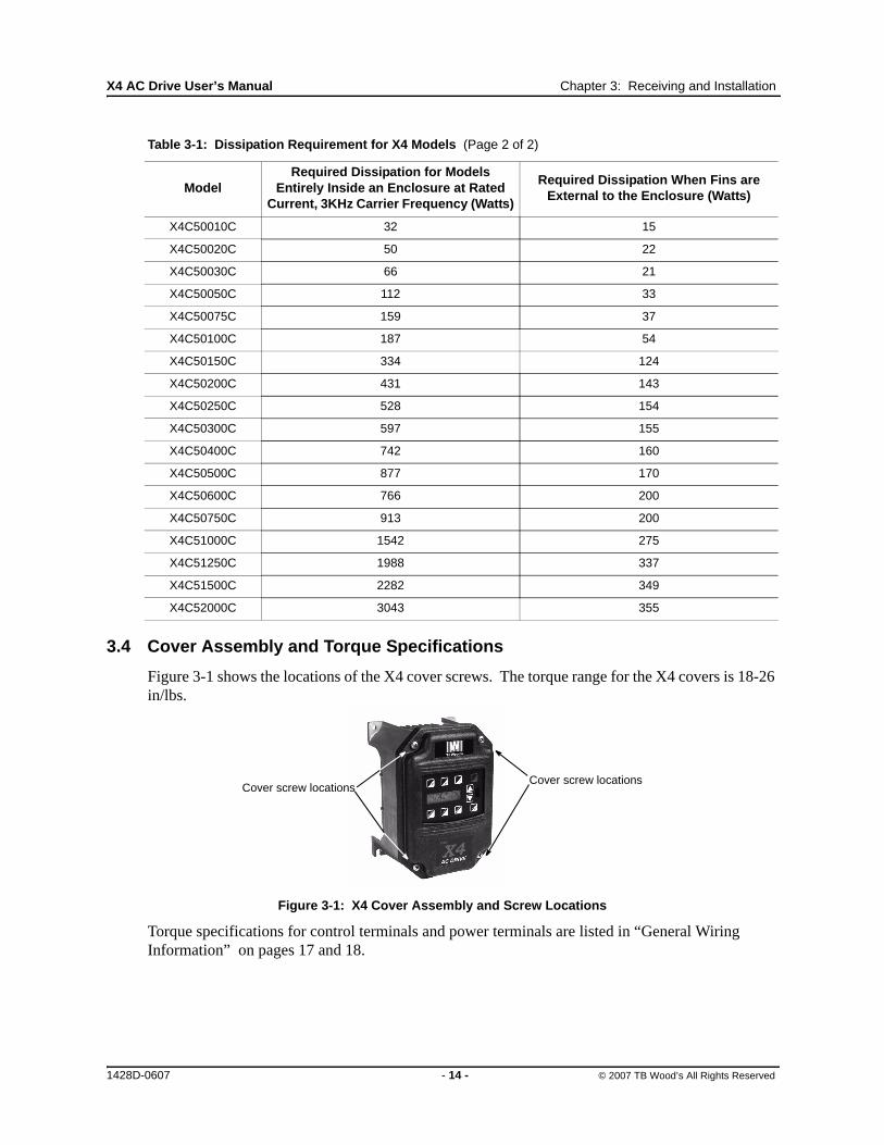
Table 3-1: Dissipation Requirement for X4 Models (Page 1 of 2)
ModelRequired Dissipation for Models
Entirely Inside an Enclosure at Rated Current, 3KHz Carrier Frequency (Watts)
Required Dissipation When Fins are External to the Enclosure (Watts)
X4C1S010C 47 13
X4C20010C 48 14
X4C20020C 71 17
X4C20030C 92 16
X4C20050C 132 20
X4C20075C 177 23
X4C20100C 263 67
X4C20150C 362 68
X4C20200C 550 97
X4C20250C 653 96
X4C20300C 779 103
X4C40010C 34 13
X4C40020C 46 16
X4C40030C 71 20
X4C40050C 91 21
X4C40075C 114 28
X4C40100C 155 30
X4C40150C 304 77
X4C40200C 393 76
X4C40250C 459 78
X4C40300C 458 77
X4C40400C 695 95
X4C40500C 834 100
X4C40600C 776 130
X4C40750C 988 135
X4C41000C 1638 155
X4C41250C 1656 353
X4C41500C 1891 372
X4C42000C 2302 382
1428D-0607 - 13 - © 2007 TB Wood’s All Rights Reserved
X4 AC Drive User’s Manual Chapter 3: Receiving and Installation
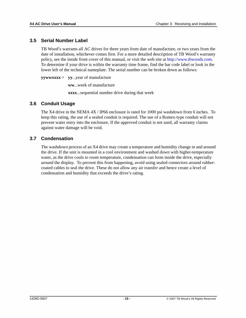
3.4 Cover Assembly and Torque Specifications
Figure 3-1 shows the locations of the X4 cover screws. The torque range for the X4 covers is 18-26 in/lbs.
Figure 3-1: X4 Cover Assembly and Screw Locations
Torque specifications for control terminals and power terminals are listed in “General Wiring Information” on pages 17 and 18.
X4C50010C 32 15
X4C50020C 50 22
X4C50030C 66 21
X4C50050C 112 33
X4C50075C 159 37
X4C50100C 187 54
X4C50150C 334 124
X4C50200C 431 143
X4C50250C 528 154
X4C50300C 597 155
X4C50400C 742 160
X4C50500C 877 170
X4C50600C 766 200
X4C50750C 913 200
X4C51000C 1542 275
X4C51250C 1988 337
X4C51500C 2282 349
X4C52000C 3043 355
Table 3-1: Dissipation Requirement for X4 Models (Page 2 of 2)
ModelRequired Dissipation for Models
Entirely Inside an Enclosure at Rated Current, 3KHz Carrier Frequency (Watts)
Required Dissipation When Fins are External to the Enclosure (Watts)
Cover screw locationsCover screw locations
1428D-0607 - 14 - © 2007 TB Wood’s All Rights Reserved
X4 AC Drive User’s Manual Chapter 3: Receiving and Installation
3.5 Serial Number Label
TB Wood’s warrants all AC drives for three years from date of manufacture, or two years from the date of installation, whichever comes first. For a more detailed description of TB Wood’s warranty policy, see the inside front cover of this manual, or visit the web site at http://www.tbwoods.com. To determine if your drive is within the warranty time frame, find the bar code label or look in the lower left of the technical nameplate. The serial number can be broken down as follows:
yywwxxxx = yy...year of manufacture
ww...week of manufacture
xxxx...sequential number drive during that week
3.6 Conduit Usage
The X4 drive in the NEMA 4X / IP66 enclosure is rated for 1000 psi washdown from 6 inches. To keep this rating, the use of a sealed conduit is required. The use of a Romex-type conduit will not prevent water entry into the enclosure. If the approved conduit is not used, all warranty claims against water damage will be void.
3.7 Condensation
The washdown process of an X4 drive may create a temperature and humidity change in and around the drive. If the unit is mounted in a cool environment and washed down with higher-temperature water, as the drive cools to room temperature, condensation can form inside the drive, especially around the display. To prevent this from happening, avoid using sealed connectors around rubber-coated cables to seal the drive. These do not allow any air transfer and hence create a level of condensation and humidity that exceeds the drive’s rating.
1428D-0607 - 15 - © 2007 TB Wood’s All Rights Reserved

Chapter 4: Connections
DANGERHAZARDOUS VOLTAGE
• Read and understand this manual in its entirety before installing or operating the X4 AC drive. Installation, adjustment, repair, and maintenance of these drives must be performed by qualified personnel.
• Disconnect all power before servicing the drive. WAIT 5 MINUTES until the DC bus capacitors discharge.
• DO NOT short across DC bus capacitors or touch unshielded components or terminal strip screw connections with voltage present.
• Install all covers before applying power or starting and stopping the drive.
• The user is responsible for conforming to all applicable code require-ments with respect to grounding all equipment.
• Many parts in this drive, including printed circuit boards, operate at line voltage. DO NOT TOUCH. Use only electrically-insulated tools.
Before servicing the drive.
• Disconnect all power.
• Place a “DO NOT TURN ON” label on the drive disconnect.
• Lock the disconnect in the open position.
Failure to observe these precautions will cause shock or burn, resulting in severe personal injury or death.
DANGERTENSION DANGEREUSE
• Lisez et comprenez ces directives dans leurs intégralité avant d’installer ou de faire fonctionner le variateur de vitesse X4. L’installation, le réglage, les réparations et l’entretien des ces variateurs de vitesse doivent être effectuées par du personnel qualifié.
• Coupez toutes les alimentations avant de travailler sur le variateur de vitesse. ATTENDEZ CINQ MINUTES pour que la décharge des condensateurs du bus cc s’effectue.
• NE court-cuitez PAS les condensateurs du bus cc ou ne touchez pas aux composantes non blindées ou aux connexions des vis du bornier si l’appareil est sous tension.
• Installez tous les couvercles avant de mettre le variateur de vitesse sous tension, de le mettre en marche ou de l’arrêter.
• L’utilisateur est responsable de la conformité avec tous les codes électriques en vigueur concernant la mise à la terre de tous les appareils.
• De nombreuses pièces de ce variateur de vitesse, y compris les cartes de circuits imprimés, fonctionnent à la tension du secteur. N’Y TOUCHEZ PAS. N’utilisez que des outils dotés d’une isolation électrique.
Avant tout entretien ou réparation sur le variateur de vitesse:
• Coupez toutes les alimentations.
• Placez une étiquette «NE PAS METTRE SOUS TENSION» sur le sectionneur du variateur de vitesse.
• Verrouillez le sectionneur en position ouverte.
Si ces précautions ne sont pas respectées, cela causera une électrocution ou des brûlures, ce qui entraînera des blessures graves ou la mort.
1428D-0607 - 16 - © 2007 TB Wood’s All Rights Reserved

X4 AC Drive User’s Manual Chapter 4: Connections
4.1 Introduction
This chapter provides information on connecting power and control wiring to the X4 AC drive.
4.2 General Wiring Information
4.2.1 Wiring PracticesWhen making power and control connections, observe these precautions:
• Never connect input AC power to the motor output terminals T1/U, T2/V, or T3/W. Damage to the drive will result.
• Power wiring to the motor must have the maximum possible separation from all other power wiring. Do not run in the same conduit; this separation reduces the possibility of coupling electrical noise between circuits.
• Cross conduits at right angles whenever power and control wiring cross.
• Good wiring practice also requires separation of control circuit wiring from all power wiring. Since power delivered from the drive contains high frequencies which may cause interference with other equipment, do not run control wires in the same conduit or raceway with power or motor wiring.
4.2.2 Considerations for Power WiringPower wiring refers to the line and load connections made to terminals L1/R, L2/S, L3/T, and T1/U, T2/V, T3/W respectively. Select power wiring using these guidelines:
• Use only UL-recognized wire.
• Wire voltage rating must be a minimum of 300 V for 230 Vac systems and 600 V (Class 1 wire) for 460 or 575 Vac systems.
• Wire gauge must be selected based on 125% of the continuous input current rating of the drive. Wire gauge must be selected from wire tables for 75 °C insulation rating, and must be of copper construction. The 230 V 7.5 and 15 HP models, and the 460 V 30 HP models require 90 °C wire to meet UL requirements. See Chapter 2 for the continuous output ratings for the drive.
• Grounding must be in accordance with NEC and CEC. If multiple X4 drives are installed near each other, each must be connected to ground. Take care not to form a ground loop.
See Table 4-1 on page 18 for a summary of power terminal wiring specifications.
1428D-0607 - 17 - © 2007 TB Wood’s All Rights Reserved

X4 AC Drive User’s Manual Chapter 4: Connections
Note: Wire type not specified by the manufacturer. Some types of wire may not fit within the constraints of the conduit entry and bend radius inside the drive.
4.2.3 Considerations for Control WiringControl wiring refers to the wires connected to the control terminal strip. Select control wiring as follows:
• Shielded wire is recommended to prevent electrical noise interference from causing improper operation or nuisance tripping.
• Use only UL recognized wire.
• Wire voltage rating must be at least 300 V for 230 Vac systems. It must be at least 600 V for 460 or 575 Vac systems.
See Table 4-2 below for a summary of power terminal control wiring specifications.
4.3 Input Line Requirements
4.3.1 Line VoltageSee “Power and Current Ratings” on page 4 for the allowable fluctuation of AC line voltage for your particular X4 model. A supply voltage above or below the limits given in the table will cause the drive to trip with either an overvoltage or undervoltage fault.
Exercise caution when applying the X4 AC drive on low-line conditions.
Table 4-1: X4 Power Terminal Wiring Specifications
X4 Size / Models Specifications
Size 0
12 in-lbs nominal torque or13 in-lbs maximum torque
12-24 awg wire5/16” (0.3125”) strip length
Size 1
16 in-lbs nominal torque or18 in-lbs maximum torque
8-18 awg wire5/16” (0.3125”) strip length
Size 230 in-lbs nominal torque
6-8 awg wire3/8” (0.38”) strip length
Size 335 in-lbs nominal torque
3 awg wire
Size 465 in-lbs nominal torque
3/0 awg wire max
Size 5132 in-lbs nominal torque
250MCM wire max
Table 4-2: X4 Control Wiring Specifications
X4 Size / Models Specifications
All Sizes / Models4.4 in-lbs maximum torque
12-24 awg wire9/32” strip length
1428D-0607 - 18 - © 2007 TB Wood’s All Rights Reserved
X4 AC Drive User’s Manual Chapter 4: Connections
For example, an X4 2000 series unit will operate properly on a 208 Vac line, but the maximum output voltage will be limited to 208 Vac. If a motor rated for 230 Vac line voltage is controlled by this drive, higher motor currents and increased heating will result.
Therefore, ensure that the voltage rating of the motor matches the applied line voltage.
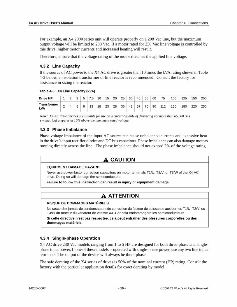
4.3.2 Line CapacityIf the source of AC power to the X4 AC drive is greater than 10 times the kVA rating shown in Table 4-3 below, an isolation transformer or line reactor is recommended. Consult the factory for assistance in sizing the reactor.
Note: X4 AC drive devices are suitable for use on a circuit capable of delivering not more than 65,000 rms symmetrical amperes at 10% above the maximum rated voltage.
4.3.3 Phase ImbalancePhase voltage imbalance of the input AC source can cause unbalanced currents and excessive heat in the drive’s input rectifier diodes and DC bus capacitors. Phase imbalance can also damage motors running directly across the line. The phase imbalance should not exceed 2% of the voltage rating.
4.3.4 Single-phase OperationX4 AC drive 230 Vac models ranging from 1 to 5 HP are designed for both three-phase and single-phase input power. If one of these models is operated with single-phase power, use any two line input terminals. The output of the device will always be three-phase.
The safe derating of the X4 series of drives is 50% of the nominal current (HP) rating. Consult the factory with the particular application details for exact derating by model.
Table 4-3: X4 Line Capacity (kVA)
Drive HP 1 2 3 5 7.5 10 15 20 25 30 40 50 60 75 100 125 150 200
Transformer kVA
2 4 5 9 13 18 23 28 36 42 57 70 90 112 150 180 220 250
EQUIPMENT DAMAGE HAZARD
Never use power-factor correction capacitors on motor terminals T1/U, T2/V, or T3/W of the X4 AC drive. Doing so will damage the semiconductors.
Failure to follow this instruction can result in injury or equipment damage.
CAUTION
RISQUE DE DOMMAGES MATÉRIELS
Ne raccordez jamais de condensateurs de correction du facteur de puissance aux bornes T1/U, T2/V, ou T3/W du moteur du variateur de vitesse X4. Car cela endommagera les semiconducteurs.
Si cette directive n’est pas respectée, cela peut entraîner des blessures corporelles ou des dommages matériels.
ATTENTION
1428D-0607 - 19 - © 2007 TB Wood’s All Rights Reserved

X4 AC Drive User’s Manual Chapter 4: Connections
4.3.5 Ground Fault Circuit InterruptersX4 drives rated for 115 Vac are not designed to operate with ground fault circuit interrupters (GFCI). The GFCI breakers are designed for residential use to protect personnel from stray currents to ground. Most GFCI breakers will shut off at 5 mA of leakage. It is not uncommon for an AC drive to have 30 to 60 mA of leakage.
4.3.6 Motor Lead LengthTB Wood’s recommends that the total lead length should not exceed the motor manufacturer’s guidelines. Line disturbance and noise can be present in motor wiring of any distance. As a rule of thumb, any non-inverter duty motor should have a reactor or filter added when the motor lead length exceeds 150 feet. The carrier frequency for the drive should also be reduced using parameter 803 (PWM Frequency).
Nuisance trips can occur due to capacitive current flow to ground. These currents can cause shock to personnel and can create problems within the motor. Care should be taken when working in these areas.
Some applications can have a restricted lead length because of type of wire, motor type, or wiring placement. Consult the factory and the motor manufacturer for additional information.
4.3.7 Using Output ContactorsContactors in the output wiring of an AC drive may be needed as part of the approved safety circuit. Problems can arise if these contactors are opened for the safety circuit and the drive is left in run mode of operation. When the contactor is open, the drive is in a no-load, no-resistance state, but is still trying to supply current to the motor. However, when the contactor closes, the drive sees the motor resistance and instantly demands current. This inrush of current when the contactor closes can fault or cause failure to the drive.
To prevent problems, interlock an auxiliary contact to the drive’s Run or Enable circuit to stop the drive when the contactor opens. In this way, the drive will be disabled and no inrush will occur when the contactor is closed again.
4.4 Terminals Found on the X4 Power Board
4.4.1 Description of the TerminalsTable 4-4 describes the X4 power terminals.
Note that earth ground is on the terminal strip (see Figure 4-1 below). Dynamic brake (DB) connections are not on the terminal strip, but on “fast on” (spade) connectors for models up to 30 HP,
Table 4-4: Description of X4 Power Terminals
Terminal Description
L1/RL2/SL3/T
These terminals are the line connections for input power. (Single-phase 115 and 230 Vac, 1 to 5 HP models connect to any two of these terminals.)
T1/UT2/VT3/W
These terminals are for motor connections.
1428D-0607 - 20 - © 2007 TB Wood’s All Rights Reserved

X4 AC Drive User’s Manual Chapter 4: Connections
and on the terminal strip for models 40 HP and larger. See page 23 for specific information about dynamic braking.
Figure 4-1: X4 Power Terminals
Figure 4-2: Power Terminals on Higher-HP Models
4.4.2 Typical Power ConnectionsSee Section 4.3 starting on page 18 for input line requirements.
Note that when testing for a ground fault, do not short any motor lead (T1/U, T2/V, or T3/W) back to an input phase (L1/R, L2/S, or L3/T).
1428D-0607 - 21 - © 2007 TB Wood’s All Rights Reserved
X4 AC Drive User’s Manual Chapter 4: Connections
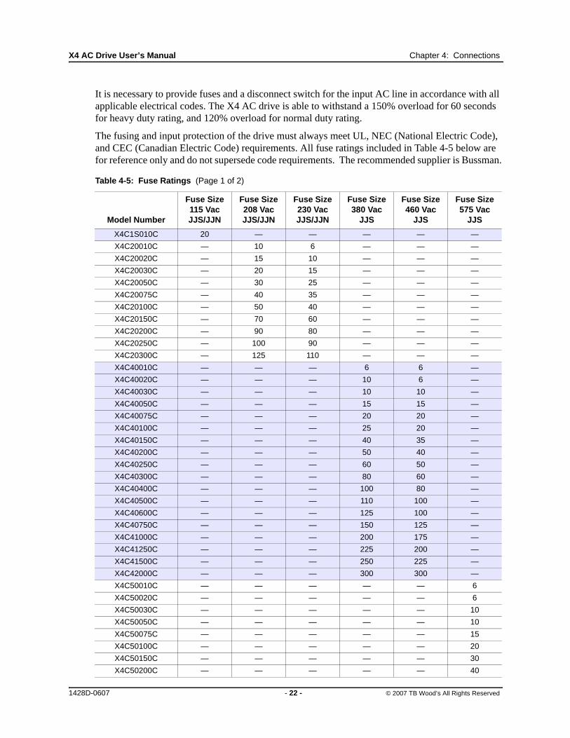
It is necessary to provide fuses and a disconnect switch for the input AC line in accordance with all applicable electrical codes. The X4 AC drive is able to withstand a 150% overload for 60 seconds for heavy duty rating, and 120% overload for normal duty rating.
The fusing and input protection of the drive must always meet UL, NEC (National Electric Code), and CEC (Canadian Electric Code) requirements. All fuse ratings included in Table 4-5 below are for reference only and do not supersede code requirements. The recommended supplier is Bussman.
Table 4-5: Fuse Ratings (Page 1 of 2)
Model Number
Fuse Size 115 VacJJS/JJN
Fuse Size 208 VacJJS/JJN
Fuse Size 230 VacJJS/JJN
Fuse Size 380 Vac
JJS
Fuse Size 460 Vac
JJS
Fuse Size 575 Vac
JJS
X4C1S010C 20 — — — — —
X4C20010C — 10 6 — — —
X4C20020C — 15 10 — — —
X4C20030C — 20 15 — — —
X4C20050C — 30 25 — — —
X4C20075C — 40 35 — — —
X4C20100C — 50 40 — — —
X4C20150C — 70 60 — — —
X4C20200C — 90 80 — — —
X4C20250C — 100 90 — — —
X4C20300C — 125 110 — — —
X4C40010C — — — 6 6 —
X4C40020C — — — 10 6 —
X4C40030C — — — 10 10 —
X4C40050C — — — 15 15 —
X4C40075C — — — 20 20 —
X4C40100C — — — 25 20 —
X4C40150C — — — 40 35 —
X4C40200C — — — 50 40 —
X4C40250C — — — 60 50 —
X4C40300C — — — 80 60 —
X4C40400C — — — 100 80 —
X4C40500C — — — 110 100 —
X4C40600C — — — 125 100 —
X4C40750C — — — 150 125 —
X4C41000C — — — 200 175 —
X4C41250C — — — 225 200 —
X4C41500C — — — 250 225 —
X4C42000C — — — 300 300 —
X4C50010C — — — — — 6
X4C50020C — — — — — 6
X4C50030C — — — — — 10
X4C50050C — — — — — 10
X4C50075C — — — — — 15
X4C50100C — — — — — 20
X4C50150C — — — — — 30
X4C50200C — — — — — 40
1428D-0607 - 22 - © 2007 TB Wood’s All Rights Reserved

X4 AC Drive User’s Manual Chapter 4: Connections
4.5 Dynamic Braking
The X4 AC drive is supplied with an integrated dynamic braking (DB) resistor, and is designed to have adequate dynamic braking for most applications. In cases where short stopping times or high inertia loads require additional braking capacity, install an external resistor.
Note: External braking cannot be added to Size 0 models. For Size 4 (60-100 HP) and Size 5 (125-200 HP) models, additional external dynamic braking requires a kit that provides the connections to the braking transistors. The XDBKITS4 and XDBKITS5 kits can be purchased through local distributors.
If an external resistor is used for dynamic braking (not applicable for Size 0 models), the internal resistor must be disconnected. Internal DB resistors are connected with fast-on terminals. To install an external resistor, first disconnect the internal DB resistor (or resistors in 460 and 575 Vac models) and properly terminate the wires leading to it. Then connect the external resistor fast-on terminals where the internal resistor had been connected.
Changes to parameter 410 (DB Config) must be made when using external DB resistors.
Verify with the manufacturer of the selected resistor that the resistor is appropriate for your application. Contact TB Wood’s Electronic Application Engineering for further assistance with other possible sizing limitations.
Refer to Table 4-6 on page 24 for information about dynamic braking capacity for each X4 model.
X4C50250C — — — — — 50
X4C50300C — — — — — 50
X4C50400C — — — — — 70
X4C50500C — — — — — 80
X4C50600C — — — — — 90
X4C50750C — — — — — 110
X4C51000C — — — — — 150
X4C51250C — — — — — 175
X4C51500C — — — — — 200
X4C52000C — — — — — 250
Table 4-5: Fuse Ratings (Page 2 of 2)
Model Number
Fuse Size 115 VacJJS/JJN
Fuse Size 208 VacJJS/JJN
Fuse Size 230 VacJJS/JJN
Fuse Size 380 Vac
JJS
Fuse Size 460 Vac
JJS
Fuse Size 575 Vac
JJS
1428D-0607 - 23 - © 2007 TB Wood’s All Rights Reserved

X4 AC Drive User’s Manual Chapter 4: Connections
Table 4-6: X4 Dynamic Braking Capacity (Page 1 of 2) (* Note that the asterisked X4 model numbers cannot have external braking added)
Model KWStandard
ResistanceStandard DB %
of DriveMin. Allowed
Res.Max. Peak
WattsMax. Ext. DB %
of Drive
1S010* .75 125 164% 125 1,223 164%
20010* .75 125 164% 125 1,223 164%
20020* 1.5 125 82% 125 1,223 82%
20030* 2.2 125 55% 125 1,223 55%
20050 3.7 60 68% 43 3,555 95%
20075 5.5 60 45% 30 5,096 91%
20100 7.5 60 34% 27 5,662 76%
20150 11 60 23% 20 7,644 68%
20200 15 30 34% 10 15,288 102%
20250 18 30 27% 10 15,288 82%
20300 22 30 23% 10 15,288 68%
40010* .75 500 163% 270 2,253 302%
40020* 1.5 500 82% 270 2,253 151%
40030* 2.2 500 54% 270 2,253 101%
40050 3.7 120 136% 100 6,084 163%
40075 5.5 120 91% 75 8,112 145%
40100 7.5 120 68% 75 8,112 109%
40150 11 120 45% 47 12,944 116%
40200 15 120 34% 47 12,944 87%
40250 18 120 27% 47 12,944 69%
40300 22 120 23% 39 15,600 70%
40400 29.8 60 34% 20 30,420 102%
40500 37.3 60 27% 20 30,420 82%
40600 45 60 23% 15 40,560 91%
40750 55 60 18% 10 60,840 109%
41000 75 60 14% 10 60,840 82%
41250 90 60 11% 10 60,840 65%
41500 110 60 9% 10 60,840 54%
42000 132 60 7% 10 60,840 41%
50010 .75 120 1058% 110 8,607 1154%
50020 1.5 120 529% 110 8,607 577%
50030 2.2 120 353% 110 8,607 385%
50050 3.7 120 212% 110 8,607 231%
50075 5.5 120 141% 91 10,404 186%
50100 7.5 120 106% 91 10,404 139%
1428D-0607 - 24 - © 2007 TB Wood’s All Rights Reserved

X4 AC Drive User’s Manual Chapter 4: Connections
4.6 Terminals Found on the X4 Control Board
4.6.1 Description of the Control Terminals
Figure 4-3 shows the control terminals found on the I/O board of the X4 AC drive. See page 6 for specifications. Table 4-7 on page 26 describes the control terminals.
The drive’s control terminals are referenced to earth ground through a resistor / capacitor network. Use caution when connecting analog signals not referenced to earth ground, especially if the communications port (J3) is being used. The J3 port includes a common reference that can be connected to earth ground through the host PLC or computer.
Figure 4-3: X4 Control Terminals
50150 11 120 71% 62 15,269 136%
50200 15 120 53% 62 15,269 102%
50250 18 120 42% 62 15,269 82%
50300 22 120 35% 62 15,269 68%
50400 29.8 60 53% 24 39,447 132%
50500 37.3 60 42% 24 39,447 106%
50600 45 60 35% 15 63,115 141%
50750 55 60 28% 15 63,115 113%
51000 75 60 21% 20 63,115 85%
51250 90 60 17% 10 94,672 102%
51500 110 60 14% 10 94,672 85%
52000 132 60 11% 10 94,672 63%
Table 4-6: X4 Dynamic Braking Capacity (Page 2 of 2) (* Note that the asterisked X4 model numbers cannot have external braking added)
Model KWStandard
ResistanceStandard DB %
of DriveMin. Allowed
Res.Max. Peak
WattsMax. Ext. DB %
of Drive
1428D-0607 - 25 - © 2007 TB Wood’s All Rights Reserved

X4 AC Drive User’s Manual Chapter 4: Connections
Table 4-7: Description of X4 Control Terminals (Page 1 of 2)
Terminal Description
Vmet Analog output 1, which is a dedicated voltage output.
The default signal range is from 0 to 10 Vdc (5 mA maximum). It is proportional to the variable configured by parameter 700 (Vmet Config) (see page 65). It may be calibrated while the drive is running via parameter 701 (Vmet Span) (see page 65).
Imet Analog output 2, which is a dedicated current output.
The default signal ranges from 0 to 20 mAdc (50 to 500 Ω). It is proportional to the variable configured by parameter 702 (Imet Config) (see page 65).It may be calibrated while the drive is running via parameters 704 (Imet Offset) and 703 (Imet Span) (see page 65).
Vin1 Analog Input 1, which is used to provide speed references.
The default input signal is 0 to 10 Vdc (the type of input signal is selected with parameter 205 (Vin1 Config); see page 53). Parameters 206 (Vin1 Offset) and 207 (Vin1 Span) may be used to offset the starting value of the range and the size of the range, respectively; see page 53 for more information.
If a 0 to 20 mAdc input signal is configured, the burden is 250 Ω. If a 0 to 10 Vdc input signal is configured, the input impedance is 475 kΩ.
A potentiometer with a range of 1 to 2 kΩ is suggested for this input.
+10 This terminal is a +10 Vdc source for customer-supplied potentiometers. The maximum load on this supply cannot exceed 10 mAdc.
Cin+ / Cin- Current Input.
The default input signal is 4-20 mA, although this range may be adjusted by using parameters 209 (Cin Offset) (which configures an offset for the range) and 210 (Cin Span) (to reduce or enlarge the range — for example, setting this parameter to 50% results in a range of 4-12 mA). See page 54 for more information on these parameters.
The burden for this terminal is 50 Ω.
Vin2 Voltage Input 2, which is used to provide speed references.
The default input signal is 0 to 10 Vdc (the type of input signal is selected with parameter 211 (Vin2 Config); see page 54). Parameters 212 (Vin2 Offset) and 213 (Vin2 Span) may be used to offset the starting value of the range and the size of the range, respectively; see page 54 for more information.
If a 0 to 20 mAdc input signal is configured, the burden is 250 Ω. If a 0 to 10 Vdc input signal is configured, the input impedance is 475 kΩ.
A potentiometer with a range of 1 to 2 kΩ is suggested for this input.
Acom Common for the Analog Inputs and Outputs. Note that while there are three Acom (common) terminals, they connect to the same electrical point.
+24 A source for positive nominal 24 Vdc voltage, and has a source capacity of 150 mA.
FWD Forward Direction Selection terminal. This may be connected for two-wire maintained or three-wire momentary operation.
REV Reverse Direction Selection Terminal. This may be connected for two-wire maintained or three-wire momentary operation.
1428D-0607 - 26 - © 2007 TB Wood’s All Rights Reserved

X4 AC Drive User’s Manual Chapter 4: Connections
R/J Run/Jog Selector. When this terminal is connected to +24 or common (depending upon Active Logic setting), momentarily connecting either FWD or REV to +24 results in a latched run mode (3-wire operation).
MOL Motor Overload input terminal. This requires a N/O or N/C contact for operation, referenced to +24 or COM, depending on Active Logic setting.
EN Enable terminal. A jumper is placed between this terminal and the +24 terminal at the factory. You may replace this with a contact, if desired. The circuit from EN to +24 must be closed for the drive to operate.
Note that unlike all other terminals, this terminal cannot be configured for “pull-down logic.” That is, a high input to this terminal is always regarded as true, and must be present for the drive to operate.
Dcom Digital Common for use with digital inputs and +24 internal power.
DI1-DI5 Digital inputs.
The function of a digital input is configured by the parameter with the same name as the digital input (for example, DI2 is configured by parameter 722 (DI2 Configure); see page 67.
NC1NO1RC1
The first auxiliary relay.
The function of the relay is set by parameter 705 (Relay 1 Select) (see page 66); the default setting is for the relay to activate when the motor is at speed.
Terminal NO1 is the normally-open contact, which closes when the relay is activated. Terminal NC1 is the normally-closed contact, which opens when the relay is activated. Terminal RC1 is the common terminal.
NC2NO2RC2
The second auxiliary relay.
The function of the relay is set by parameter 706 (Relay 2Select) (see page 66); the default setting is for the relay to activate when a fault occurs.
Terminal NO2 is the normally-open contact; it will close when the relay is activated. RC2 is the common terminal.
DO1DO2
Digital Outputs 1 and 2.
The function of the outputs is set by parameters 707 (DO1 Select) and 708 (DO2 Select). The default setting for DO1 is Drive Ready; for DO2 it is At Speed. See page 66.
DOP Open collector transistor output that supplies a pulse train proportional to speed. The frequency of the output is set by parameter 812 (Freq Ref Output) to either 6x or 48x the running frequency. The output has a maximum rating of 28 Vdc and requires a pull-up resistor (4.7 kOhms) if using the drive’s internal supply.
Note that if you are using a high-impedance meter to this terminal, the pull-up resistor value may need to change. Please consult the factory for more information.
Table 4-7: Description of X4 Control Terminals (Page 2 of 2)
Terminal Description
1428D-0607 - 27 - © 2007 TB Wood’s All Rights Reserved

X4 AC Drive User’s Manual Chapter 4: Connections
4.6.2 Typical Connection Diagrams for Digital Inputs
Figure 4-4: Connections for 2-wire and 3-wire Control
Figure 4-5: Connections for Preset Speeds
Typical connection for 2-wire control
Typical connection for 3-wire control
Table 4-8: Selection of Preset Speeds
PS3 (Bit 3) PS2 (Bit 2) PS1 (Bit 1) Speed Selected
0 0 0 Normal reference speed as defined by parameters 201 (Input Mode) and 204 (Ref Select)
0 0 1 Preset frequency F1 (303-F1).
0 1 0 Preset frequency F2 (304-F2).
0 1 1 Preset frequency F3 (305-F3).
1 0 0 Preset frequency F4 (306-F4).
1 0 1 Preset frequency F5 (307-F5).
1 1 0 Preset frequency F6 (308-F6).
1 1 1 Maximum frequency (302, Max Frequency).
1428D-0607 - 28 - © 2007 TB Wood’s All Rights Reserved
X4 AC Drive User’s Manual Chapter 4: Connections
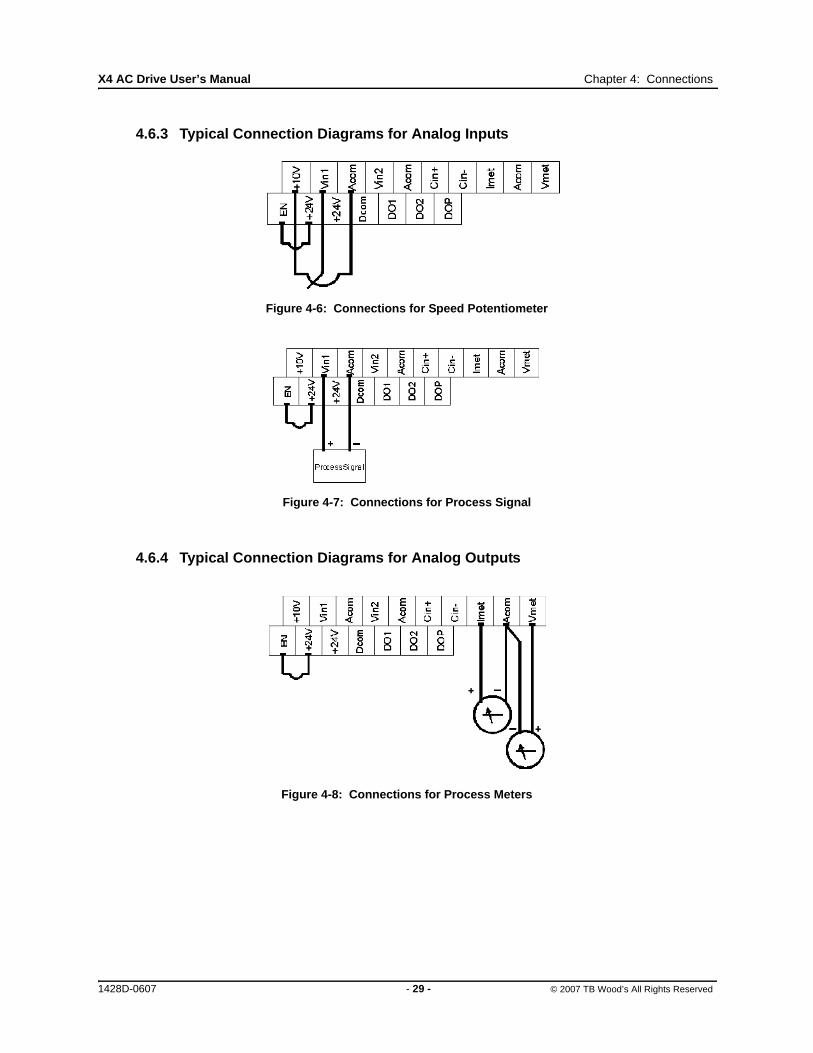
4.6.3 Typical Connection Diagrams for Analog Inputs
Figure 4-6: Connections for Speed Potentiometer
Figure 4-7: Connections for Process Signal
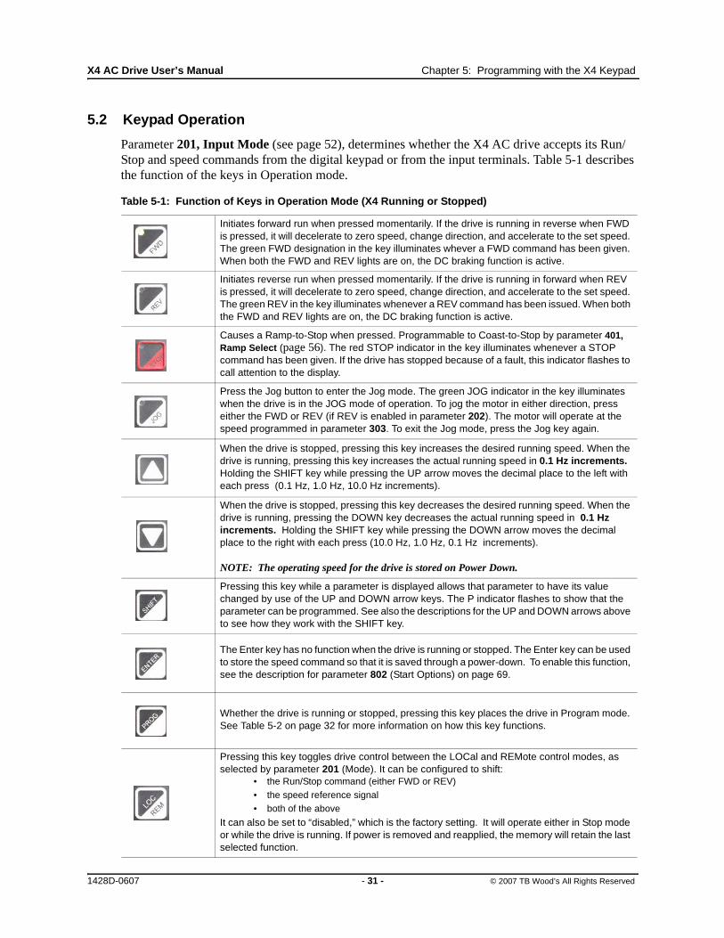
4.6.4 Typical Connection Diagrams for Analog Outputs
Figure 4-8: Connections for Process Meters
1428D-0607 - 29 - © 2007 TB Wood’s All Rights Reserved

Chapter 5: Keypad Operation and Programming
5.1 Introduction
The X4 AC drive is pre-programmed to run a standard, 4-pole AC induction motor. For many applications, the drive is ready for use right out of the box with no additional programming needed. The digital keypad controls all operations of the unit. The ten input keys allow “press and run” operation of the motor (Operation mode) and straightforward programming of the parameters (Program mode)..
Figure 5-1: The X4 Keypad
To simplify programming, the parameters are grouped into three levels:
1. Enter Level 1 by pressing the Program (PROG) key at any time. Level 1 allows you to access the most commonly used parameters.
2. Enter Level 2 by holding down the SHIFT key while pressing the PROG key. Level 2 allows access to all X4 parameters, including those in Level 1, for applications which require more advanced features.
3. Enter Macro mode by holding the Program (PROG) key down for more than 3 seconds. The display then shows “Hold PROG for Macro Mode.” See Chapter 6, “Using Macro Mode,” starting on page 39, for more information.
The summary of parameters found before the Table of Contents notes whether a parameter is in Level 1. “Chapter 7: X4 Parameters” on page 49 gives full information about what level a parameter is in.
If you want to get started quickly, see the “Quick Start” section on page 48.
1428D-0607 - 30 - © 2007 TB Wood’s All Rights Reserved
X4 AC Drive User’s Manual Chapter 5: Programming with the X4 Keypad
5.2 Keypad Operation
Parameter 201, Input Mode (see page 52), determines whether the X4 AC drive accepts its Run/Stop and speed commands from the digital keypad or from the input terminals. Table 5-1 describes the function of the keys in Operation mode.
Table 5-1: Function of Keys in Operation Mode (X4 Running or Stopped)
Initiates forward run when pressed momentarily. If the drive is running in reverse when FWD is pressed, it will decelerate to zero speed, change direction, and accelerate to the set speed. The green FWD designation in the key illuminates whever a FWD command has been given. When both the FWD and REV lights are on, the DC braking function is active.
Initiates reverse run when pressed momentarily. If the drive is running in forward when REV is pressed, it will decelerate to zero speed, change direction, and accelerate to the set speed. The green REV in the key illuminates whenever a REV command has been issued. When both the FWD and REV lights are on, the DC braking function is active.
Causes a Ramp-to-Stop when pressed. Programmable to Coast-to-Stop by parameter 401, Ramp Select (page 56). The red STOP indicator in the key illuminates whenever a STOP command has been given. If the drive has stopped because of a fault, this indicator flashes to call attention to the display.
Press the Jog button to enter the Jog mode. The green JOG indicator in the key illuminates when the drive is in the JOG mode of operation. To jog the motor in either direction, press either the FWD or REV (if REV is enabled in parameter 202). The motor will operate at the speed programmed in parameter 303. To exit the Jog mode, press the Jog key again.
When the drive is stopped, pressing this key increases the desired running speed. When the drive is running, pressing this key increases the actual running speed in 0.1 Hz increments. Holding the SHIFT key while pressing the UP arrow moves the decimal place to the left with each press (0.1 Hz, 1.0 Hz, 10.0 Hz increments).
When the drive is stopped, pressing this key decreases the desired running speed. When the drive is running, pressing the DOWN key decreases the actual running speed in 0.1 Hz increments. Holding the SHIFT key while pressing the DOWN arrow moves the decimal place to the right with each press (10.0 Hz, 1.0 Hz, 0.1 Hz increments).
NOTE: The operating speed for the drive is stored on Power Down.
Pressing this key while a parameter is displayed allows that parameter to have its value changed by use of the UP and DOWN arrow keys. The P indicator flashes to show that the parameter can be programmed. See also the descriptions for the UP and DOWN arrows above to see how they work with the SHIFT key.
The Enter key has no function when the drive is running or stopped. The Enter key can be used to store the speed command so that it is saved through a power-down. To enable this function, see the description for parameter 802 (Start Options) on page 69.
Whether the drive is running or stopped, pressing this key places the drive in Program mode. See Table 5-2 on page 32 for more information on how this key functions.
Pressing this key toggles drive control between the LOCal and REMote control modes, as selected by parameter 201 (Mode). It can be configured to shift:
• the Run/Stop command (either FWD or REV)• the speed reference signal• both of the above
It can also be set to “disabled,” which is the factory setting. It will operate either in Stop mode or while the drive is running. If power is removed and reapplied, the memory will retain the last selected function.
1428D-0607 - 31 - © 2007 TB Wood’s All Rights Reserved

X4 AC Drive User’s Manual Chapter 5: Programming with the X4 Keypad
Program mode is entered by stopping the X4 drive and pressing the Program (PROG) key for Level 1 access; or holding down SHIFT while pressing PROG for Level 2 access. Pressing and holding the Enter key and then pressing the Program key will show only those parameters that have been changed from the factory defaults. Table 5-2 describes the function of the keys in Program mode.
Table 5-2: Function of Keys in Program Mode
Press this key to have the drive enter Program mode and have Level 1 parameters available. (To access Level 2 parameters, hold down SHIFT while pressing this key; to access Macro mode, hold down the PROG key for more than 3 seconds.) Once Program mode is active, pressing this key at any time returns the drive to the Operation mode. If an Access Code has been programmed, it must be entered to proceed with programming. See Parameter 811 (ACODE) (page 70).
NOTE: To see what parameters have changed from the factory default, press ENTER + PROG. If the display flashes “Factory Defaults,” no parameters have changed.
In the Program mode, pressing this key scrolls forward through the parameters. If the P indicator is flashing, it increases the value of the parameter. To change the scroll rate, hold the SHIFT key at the same time to increase the scroll rate; release the SHIFT key to return to the normal scroll rate. Press the ENTER key to store the new value.
In the Program mode, pressing this key scrolls backward through the parameters. If the P indicator is flashing, it decreases the value of the parameter. To change the scroll rate, hold the SHIFT key at the same time to increase the scroll rate; release the SHIFT key to return to the normal scroll rate. Press the ENTER key to store the new value.
NOTE: If the P indicator on the keypad display is flashing, momentarily pressing and releasing both the UP and DOWN arrows at the same time restores the parameter to the factory default value. Press ENTER to store the new value.
Pressing this key while a parameter is displayed allows that parameter to have its value changed by use of the UP and DOWN arrow keys. The P indicator flashes to show that the parameter can be programmed. See also the descriptions for the UP and DOWN arrows above to see how they work with the SHIFT key.
This key must be pressed after the value of a parameter has been changed to store the new value. The display will show “stored” for one second indicating that the new value has been entered into memory.
NOTE: The X4 unit allows you to view only those parameters that have changed. If you press keypad keys ENTER and PROGram simultaneously, only those parameters that have been changed from the factory defaults will be shown.
Table 5-3: Function of Keys in Fault Mode
In Fault mode, pressing the UP and DOWN keys allows the operator to view the drive’s status immediately before the fault occurred. Use the UP and DOWN arrows to scroll through the status parameters. Press the STOP (Reset) key to return to normal operation.
See “Chapter 8: Troubleshooting” on page 83 for information about viewing Advanced Fault Codes and understanding error codes.
The red STOP indicator functions as a reset button when in Fault mode. If the drive has stopped because of a fault, this light flashes to call attention to the display.
1428D-0607 - 32 - © 2007 TB Wood’s All Rights Reserved

X4 AC Drive User’s Manual Chapter 5: Programming with the X4 Keypad
5.3 LCD Displays
The X4 drive’s digital keypad display provides information such as source of drive control, status, mode, and access rights.
5.3.1 ControlThe first 3 characters of the display show the source of control for the drive:
5.3.2 X4 Keypad Status and Warning MessagesTable 5-4 shows X4 keypad status messages that may appear during operation:
Display Values Meaning
LOC Local control via the keypad
REM Remote control from the terminal strip
SIO Remote control via the RS485 Serial SIO Link
SQx Control via the Program Sequencer
Table 5-4: Keypad Status States (Page 1 of 2)
Message Meaning
StoppedThe drive is not spinning the motor or injecting DC voltage. The drive is ready to run when given the proper signal.
FWD Accel The drive is spinning the motor in the forward direction and the speed of the motor is increasing.
REV Accel The drive is spinning the motor in the reverse direction and the speed of the motor is increasing.
FWD Decel The drive is spinning the motor in the forward direction and the speed of the motor is decreasing.
REV Decel The drive is spinning the motor in the reverse direction and the speed of the motor is decreasing.
Jog FWD The drive is jogging in the forward direction.
Jog REV The drive is jogging in the reverse direction.
FWD At SpdThe drive is spinning the motor in the forward direction and the speed of the motor is at the reference frequency.
REV At SpdThe drive is spinning the motor in the reverse direction and the speed of the motor is at the reference frequency.
Zero SpeedThe drive has an active run signal but the motor is not spinning because the reference speed to the drive must be 0.0 Hz.
DC Inject The drive is injecting DC voltage into the motor.
Faulted The drive is faulted.
Reset-Flt The drive is faulted, but has the possibility of being automatically reset.
LS LockoutLine-Start Lockout functionality has become active. This means there was an active run signal during power-up or when a fault was reset. This run signal must be removed before the Line-Start Lockout functionality will be removed.
Catch Fly The Catch on the Fly functionality is actively searching for the motor frequency.
ForwardThe drive is running forward without accelerating, decelerating or residing at the reference frequency. This means that something is keeping the drive from the reference frequency (for example, Current Limit).
1428D-0607 - 33 - © 2007 TB Wood’s All Rights Reserved

X4 AC Drive User’s Manual Chapter 5: Programming with the X4 Keypad
Table 5-5 shows X4 keypad warning messages that may appear during operation:
ReverseThe drive is running in reverse without accelerating, decelerating or residing at the reference frequency. This means that something is keeping the drive from the reference frequency (for example, Current Limit).
Not EnabledThe drive is not allowed to run either because the digital input enable is not active or because ARCTIC mode has shut down the run operation.
Volt RangeThe drive has not met the input voltage voltage requirements that it needs to be able to run. In other words, the Bus Voltage of the drive is either too low or too high.
Low Voltage The drive has reached an undervoltage state.
Kpd StopA stop command was given from the keypad when the keypad was not the active control source. To remove this condition, the run signal to the drive must be removed.
Table 5-5: Keypad Warnings
Message Meaning
DB Active The DB Resistor is being actively pulsed.
Curr Limit The drive is operating in current limit.
HS Fan Err Either the heatsink fan should be on and is off, or vice-versa.
Addr XXXThis is the node address of the drive when it receives a valid message through the IR port address to another node. The XXX will be replaced with the node address.
High TempThe temperature of either the heatsink or the control board is nearing a high temperature limit that will fault the drive.
Low TempThe temperature of either the heatsink or the control board is nearing a low temperature limit that will fault the drive.
Vac Imblnce Either the drive has lost an input phase or the input voltage is unbalanced more than 2%.
Power Supp A power supply short occurred.
Seq Dwell The sequencer is active, but the transition to the next step is halted.
Int Fan Err Either the internal fan is on and should be off, or vice-versa.
DB OverTemp The temperature of the DB Resistor is nearing a high temperature and will fault the drive.
ARCTIC Mode The ARCTIC DB Resistor mode is actively pulsing the DB Resistor.
CPU Warning A system error occurred in the software of the X4.
Mtr Measure An RS Measurement is armed or active.
IR Active Valid IR communications are occurring.
Seq Running The program sequencer functionality is active.
Table 5-4: Keypad Status States (Page 2 of 2)
Message Meaning
1428D-0607 - 34 - © 2007 TB Wood’s All Rights Reserved

X4 AC Drive User’s Manual Chapter 5: Programming with the X4 Keypad
5.3.3 RightsAfter Program mode is entered, the operator’s access rights are displayed:
5.3.4 Other DataThe top line gives 16-character description of the parameter being accessed. The parameter number will flash when data is being changed. Up to 10 characters are used to display the information stored in the parameter. Some parameters have a unit designator such as:
s Secondsh HoursC Degrees centigradeHz Hertz % PercentA Amperes
When the drive stops because of a fault trip, a unique error message will be displayed, along with the flashing STOP indicator. “Pages,” or screens of information are available concerning the actual fault and drive status.
“Chapter 8: Troubleshooting” on page 83 gives information about fault codes and troubleshooting.
5.4 Keypad Display Window
The keypad display provides information on drive operation and programming. Special symbols provide further information about drive operation (see the following section). Figure 5-2 shows an example of the X4 keypad display.
Figure 5-2: X4 Keypad Display
Display Values
ACCESS RIGHTS
P This indicates that while in Programming mode, parameter data can be changed.
VIf the drive is in Run mode (FWD or REV) when the PROG key was pressed, parameters can be viewed, but not changed.
The first character of the second line indicates if the particular parameter can be changed (P) or only examined (V). If an attempt is made to change data while in the View (V) mode, the message **NO ACCESS** will appear for one second.
1428D-0607 - 35 - © 2007 TB Wood’s All Rights Reserved
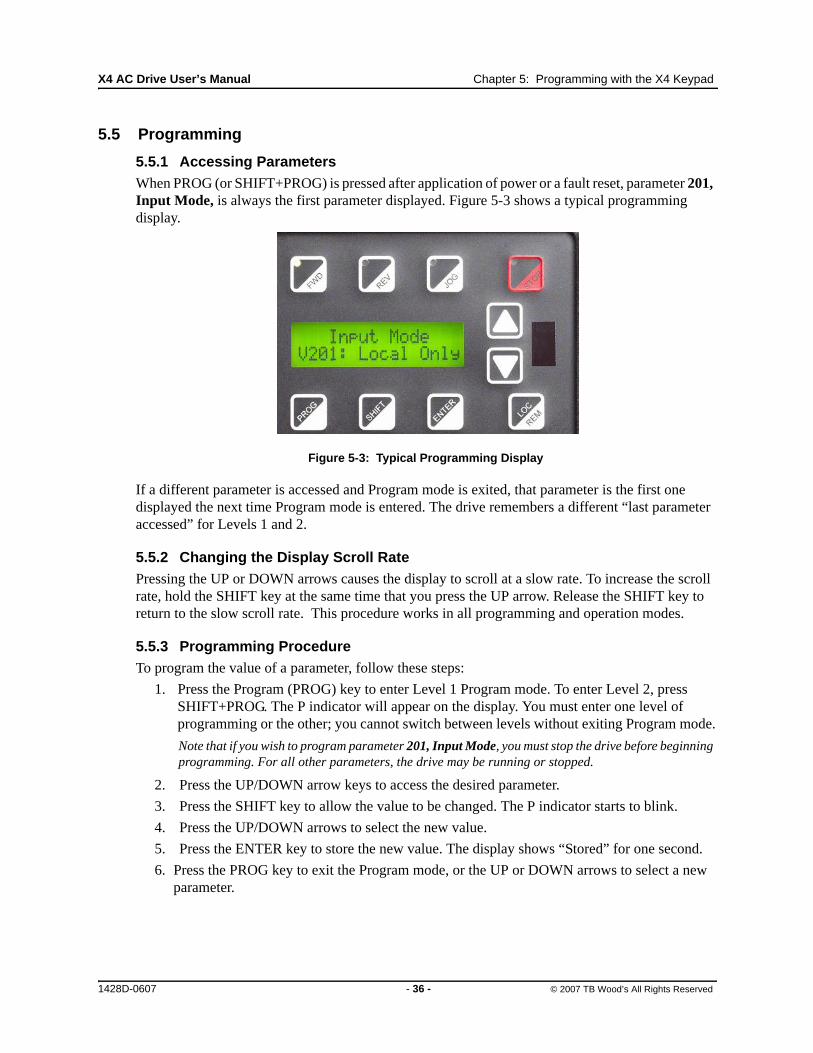
X4 AC Drive User’s Manual Chapter 5: Programming with the X4 Keypad
5.5 Programming
5.5.1 Accessing ParametersWhen PROG (or SHIFT+PROG) is pressed after application of power or a fault reset, parameter 201, Input Mode, is always the first parameter displayed. Figure 5-3 shows a typical programming display.
Figure 5-3: Typical Programming Display
If a different parameter is accessed and Program mode is exited, that parameter is the first one displayed the next time Program mode is entered. The drive remembers a different “last parameter accessed” for Levels 1 and 2.
5.5.2 Changing the Display Scroll RatePressing the UP or DOWN arrows causes the display to scroll at a slow rate. To increase the scroll rate, hold the SHIFT key at the same time that you press the UP arrow. Release the SHIFT key to return to the slow scroll rate. This procedure works in all programming and operation modes.
5.5.3 Programming ProcedureTo program the value of a parameter, follow these steps:
1. Press the Program (PROG) key to enter Level 1 Program mode. To enter Level 2, press SHIFT+PROG. The P indicator will appear on the display. You must enter one level of programming or the other; you cannot switch between levels without exiting Program mode.
Note that if you wish to program parameter 201, Input Mode, you must stop the drive before beginning programming. For all other parameters, the drive may be running or stopped.
2. Press the UP/DOWN arrow keys to access the desired parameter.
3. Press the SHIFT key to allow the value to be changed. The P indicator starts to blink.
4. Press the UP/DOWN arrows to select the new value.
5. Press the ENTER key to store the new value. The display shows “Stored” for one second.
6. Press the PROG key to exit the Program mode, or the UP or DOWN arrows to select a new parameter.
1428D-0607 - 36 - © 2007 TB Wood’s All Rights Reserved
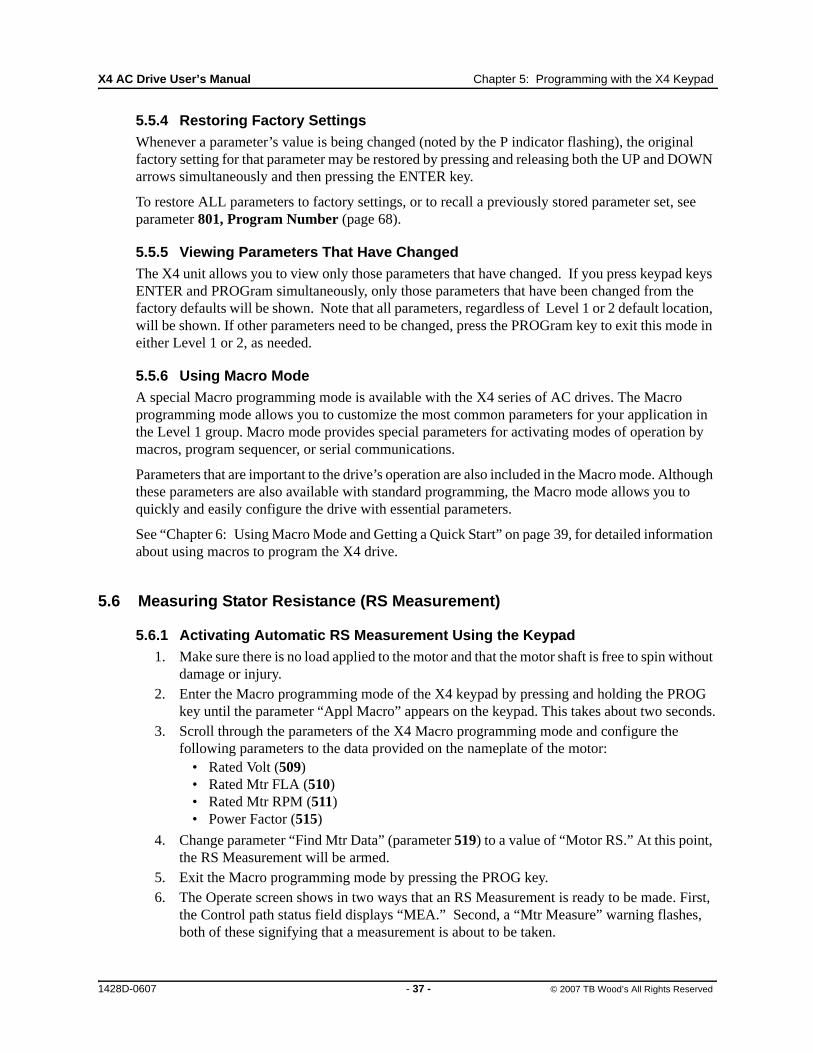
X4 AC Drive User’s Manual Chapter 5: Programming with the X4 Keypad
5.5.4 Restoring Factory SettingsWhenever a parameter’s value is being changed (noted by the P indicator flashing), the original factory setting for that parameter may be restored by pressing and releasing both the UP and DOWN arrows simultaneously and then pressing the ENTER key.
To restore ALL parameters to factory settings, or to recall a previously stored parameter set, see parameter 801, Program Number (page 68).
5.5.5 Viewing Parameters That Have ChangedThe X4 unit allows you to view only those parameters that have changed. If you press keypad keys ENTER and PROGram simultaneously, only those parameters that have been changed from the factory defaults will be shown. Note that all parameters, regardless of Level 1 or 2 default location, will be shown. If other parameters need to be changed, press the PROGram key to exit this mode in either Level 1 or 2, as needed.
5.5.6 Using Macro ModeA special Macro programming mode is available with the X4 series of AC drives. The Macro programming mode allows you to customize the most common parameters for your application in the Level 1 group. Macro mode provides special parameters for activating modes of operation by macros, program sequencer, or serial communications.
Parameters that are important to the drive’s operation are also included in the Macro mode. Although these parameters are also available with standard programming, the Macro mode allows you to quickly and easily configure the drive with essential parameters.
See “Chapter 6: Using Macro Mode and Getting a Quick Start” on page 39, for detailed information about using macros to program the X4 drive.
5.6 Measuring Stator Resistance (RS Measurement)
5.6.1 Activating Automatic RS Measurement Using the Keypad1. Make sure there is no load applied to the motor and that the motor shaft is free to spin without
damage or injury.2. Enter the Macro programming mode of the X4 keypad by pressing and holding the PROG
key until the parameter “Appl Macro” appears on the keypad. This takes about two seconds.3. Scroll through the parameters of the X4 Macro programming mode and configure the
following parameters to the data provided on the nameplate of the motor:• Rated Volt (509)• Rated Mtr FLA (510)• Rated Mtr RPM (511)• Power Factor (515)
4. Change parameter “Find Mtr Data” (parameter 519) to a value of “Motor RS.” At this point, the RS Measurement will be armed.
5. Exit the Macro programming mode by pressing the PROG key.6. The Operate screen shows in two ways that an RS Measurement is ready to be made. First,
the Control path status field displays “MEA.” Second, a “Mtr Measure” warning flashes, both of these signifying that a measurement is about to be taken.
1428D-0607 - 37 - © 2007 TB Wood’s All Rights Reserved
X4 AC Drive User’s Manual Chapter 5: Programming with the X4 Keypad
7. Start the RS Measurement by pressing the FWD key. The measurement can only be made with the FWD key. The FWD / REV terminals and the REV key will not work.
8. The measurement will begin as the drive injects voltage to the motor at zero frequency. The test lasts about two seconds.
9. If the test was successful, the drive will stop and return to the configured control path. The “Motor RS” parameter will contain a new value that is the calculated resistance of the motor.
10. If the test was not successful, the drive will fault with a “RS Meas. Fail” message (Fault 34). If the test fails, you may want to try the test again with a different “Rated Mtr FLA” or different Current Limit percentage.
5.6.2 Activating Automatic RS Measurement via Serial Link (Modbus)1. Make sure there is no load applied to the motor and that the motor shaft is free to spin without
damage or injury.2. Configure the following parameters to the data provided on the nameplate of the motor:
• Rated Volt (509)• Rated Mtr FLA (510)• Rated Mtr RPM (511)• Power Factor (515)
3. Change parameter “Find Mtr Data” (519) to a value of “Motor RS.” At this point, the RS Measurement will be armed.
4. Start the RS Measurement by writing a value of 0x0007 to parameter “SIO Cntl Word” (904).5. The measurement begins as the drive injects voltage to the motor at zero frequency. The test
lasts about two seconds.6. If the test was successful, the drive will stop and return to the configured control path. The
“Motor RS” parameter will contain a new value that is the calculated resistance of the motor.7. If the test was not successful, the drive will fault with a “RS Meas. Fail” message (Fault 34).
If the test fails, you may want to try the test again with a different “Rated Mtr FLA” or different Current Limit percentage.
1428D-0607 - 38 - © 2007 TB Wood’s All Rights Reserved

Chapter 6: Using Macro Mode and Getting a Quick Start
A special Macro programming mode is available with the X4 series of AC drives. The Macro programming mode allows you to customize quickly the most common parameters for your application in the Level 1 group. Macro mode provides special parameters for activating modes of operation by macros, program sequencer, or serial communications.
Parameters important to the drive’s operation are also included in Macro mode. Although these parameters are also available with standard programming, the Macro mode allows you to easily configure the drive with essential parameters.
Macros configure what advanced functions will be active in the drive. A macro can also change the default or visibility of a parameter within the programming levels. Parameter 490 (Appl Macro) configures what macro will be active in the drive. Parameter 491 (Seq Appl) configures the visibility of sequencer parameters and the time base of the sequencer. Parameter 492 (SIO Visible) configures whether or not SIO parameters are visible. (See page 40.)
6.1 Entering Macro Mode
To enter the Macro mode, press and hold the PROGram key for more than three seconds. The drive then enters Macro mode and displays “Hold PROG for Macro Mode.” Following is a list of the different macros available and their features. A description of parameters used in Macro mode begins on page 40.
Factory The Factory macro provides a simple way to restore the factory default parameter listings.Fan The Fan macro provides a basic set-up for Fan applications. Parameters such as the V/Hz curve
and terminal strip operation are available in Level 1 programming.Fan w/ PI The Fan w/ PI macro allows for a simple set-up for Fan applications requiring process control.
Parameters such as the V/Hz curve, terminal strip operation, and PI configuration parameters are available in Level 1 programming.
Pump The Pump macro provides a basic set-up for Pump applications. Parameters such as the V/Hz curve and terminal strip operation are available in Level 1 programming.
Pump w/ PI The Pump w/ PI macro allows for a simple set-up for Pump applications requiring process control. Parameters such as the V/Hz curve, terminal strip operation, and PI configuration parameters are available in Level 1 programming.
Vector The Vector macro activates the sensorless vector control algorithm. When an operation requires low speed and high torque, this macro should be activated.
1428D-0607 - 39 - © 2007 TB Wood’s All Rights Reserved

X4 AC Drive User’s Manual Chapter 6: Using Macro Mode / Quick Start
6.2 Description of Parameters Used in Macro Mode
Parameters 490, 491, and 492 are used only in the Macro mode. Parameters 509, 510, 511, 801, and 810 are used in both Macro and Level 2 programming. X4 parameters are described in “Chapter 7: X4 Parameters” on page 49 of this manual.
490 Appl Macro Default: Factory Range: n/aMacro
This parameter configures what macro will be active in the drive. A macro will change a default or visibility of a parameter.
The following data values may be assigned to this parameter:
Macro Description
Factory Provides a simple way to restore factory default parameter listings.Fan Provides a basic set-up for Fan applications, including V/Hz curve and terminal strip operation in Level 1
programming.
Fan w/PI Provides a simple set-up for Fan applications that require process control. Parameters such as V/Hz curve, terminal strip operation, and PI configuration are available in Level 1 programming.
Pump Provides a basic set-up for Pump applications, including V/Hz curve and terminal strip operation in Level 1 programming.
Pump w/PI Provides a simple set-up for Pump applications requiring process control. Parameters such as V/Hz curve, terminal strip operation, and PI configuration are available in Level 1 programming.
Vector Activates the sensorless vector control algorithm. When an operation requires low speed and high torque, this macro should be activated. Note that in Vector control, the drive automatically runs the Motor Rs measurements when leaving PROGram mode.
491 Seq Appl Default: Disabled Range: n/aMacro
This parameter configures sequencer parameters are visible and the time base of the sequencer. The time base may change depending on the timing loops used.
The following data values may be assigned to this parameter:
Macro Value Description
Disabled Sequencer disabled and parameters hidden.1sec Base Sequencer enabled and 1 second time base..1sec Base Sequencer enabled and 0.1 second time base..01sec Base Sequencer enabled and 0.01 second time base.
492 SIO Visible Default: No Range: n/aMacro
This parameter configures whether SIO parameters are visible.
The following data values may be assigned to this parameter:
Macro Value Description
No SIO parameters hidden.Yes SIO parameters visible.
509 Rated Mtr Volt Default: Model dependent Range: 100 V - 690 VLevel 2, Macro
The Rated Motor Voltage parameter configures the rated motor voltage, and allows a user to enter the rated voltage from the motor nameplate to provide optimal control and protection. This is usually the amount of voltage delivered to the motor terminals at the setting of 503 (V/Hz Knee Freq).
510 Rated Mtr FLA Default: ND Rating Range: 50% of ND rating - 200% of ND ratingLevel 2, Macro
The Rated Motor FLA parameter allows a user to enter the rated FLA from the motor nameplate to provide optimal control and protection. This parameter should be configured to the value on the nameplate of the motor, as that value is used in calculating the percentage of current at which the drive is operating.
For information on motor timed overload operation, and how Parameter 510 works with it, see page 64.
1428D-0607 - 40 - © 2007 TB Wood’s All Rights Reserved

X4 AC Drive User’s Manual Chapter 6: Using Macro Mode / Quick Start
511 Rated Mtr RPM Default: 1750 rpm Range: 0-24000 rpmLevel 2, Macro
This parameter replaces the slip compensation parameter setting of the drive so the user does not need to calculate it.
514 Motor RS Default: 1.00 Ohm Range: 0.00-655.35 OhmsLevel 2
This parameter allows direct entry of the Stator Resistance (Rs) of the motor for better vector performance. The motor manufacturer can provide this information. See “Measuring Stator Resistance (RS Measurement)” on page 37.
515 Power Factor Default: 0.80 Range: 0.50 - 1.00Level 2
This parameter allows direct entry of the motor’s power factor for better vector performance. The motor manufacturer can provide this information.
519 Find Mtr Data Default: Not active Range: n/aMacro
This parameter activates the drive’s ability to measure the stator resistance of the attached motor. The automatic stator resistance measurement can be performed either through the keypad or through the serial link. See “Measuring Stator Resistance (RS Measurement)” on page 37 for more information about this parameter. The following data values may be assigned:
Parameter Value Description
Not Active No stator RS measurement.Motor RS Automatic RS measurement using macro procedure.
801 Program Number Default: 0 Range: 0 to 9999Level 2, Macro
This parameter (Special Program Number) provides a method of enabling hidden functions in the drive and storing parameters to the customer set.
Data Value Special Function Configured
0 Standard program1 Reset all parameters to factory default values (display = SETP).2 Store customer parameter values (display = STOC).3 Load customer parameter values (display = SETC).4 Swap active parameters with customer stored settings.
810 Language Default: English Range: 1-65535Level 2, Macro
This parameter configures the language in which text strings will be displayed.
The following data values may be assigned to this parameter:
Parameter Value
EnglishSpanishGermanItalianFrench
1428D-0607 - 41 - © 2007 TB Wood’s All Rights Reserved
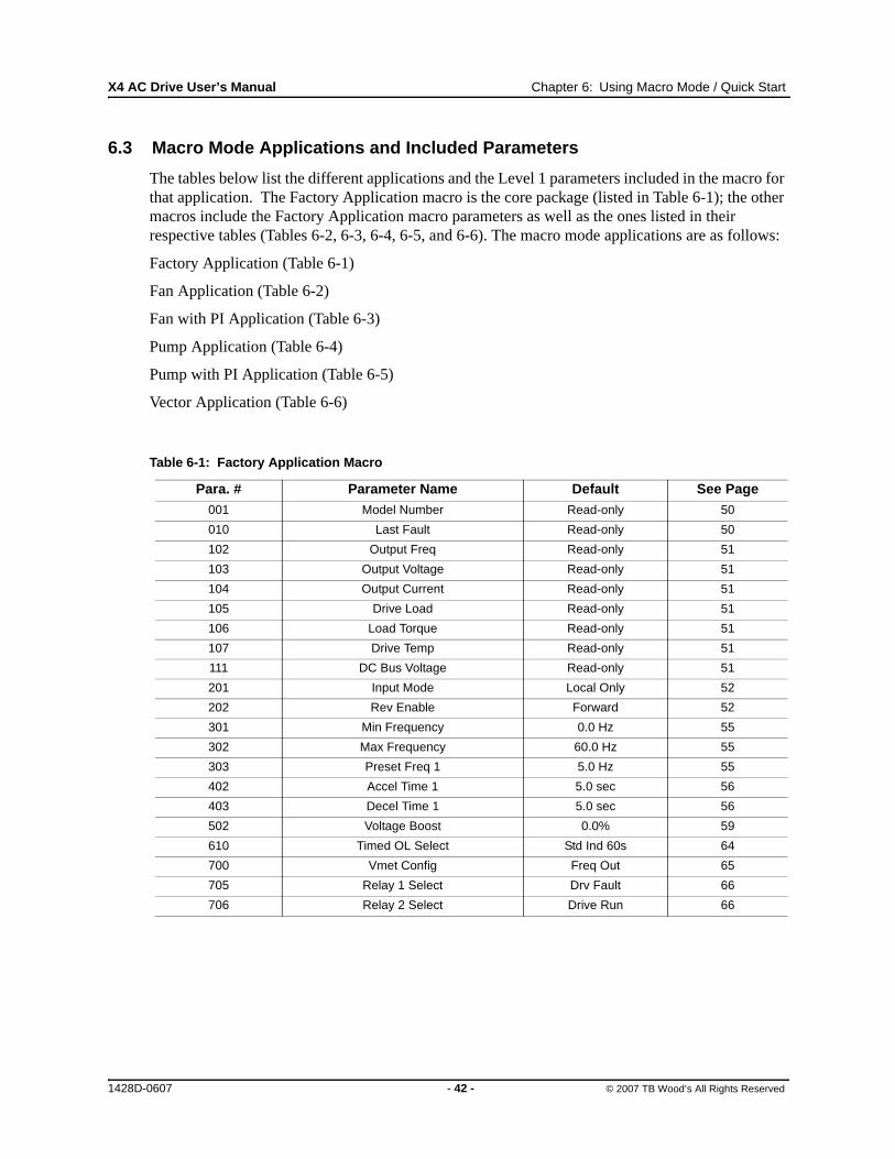
X4 AC Drive User’s Manual Chapter 6: Using Macro Mode / Quick Start
6.3 Macro Mode Applications and Included Parameters
The tables below list the different applications and the Level 1 parameters included in the macro for that application. The Factory Application macro is the core package (listed in Table 6-1); the other macros include the Factory Application macro parameters as well as the ones listed in their respective tables (Tables 6-2, 6-3, 6-4, 6-5, and 6-6). The macro mode applications are as follows:
Factory Application (Table 6-1)
Fan Application (Table 6-2)
Fan with PI Application (Table 6-3)
Pump Application (Table 6-4)
Pump with PI Application (Table 6-5)
Vector Application (Table 6-6)
Table 6-1: Factory Application Macro
Para. # Parameter Name Default See Page001 Model Number Read-only 50
010 Last Fault Read-only 50
102 Output Freq Read-only 51
103 Output Voltage Read-only 51
104 Output Current Read-only 51
105 Drive Load Read-only 51
106 Load Torque Read-only 51
107 Drive Temp Read-only 51
111 DC Bus Voltage Read-only 51
201 Input Mode Local Only 52
202 Rev Enable Forward 52
301 Min Frequency 0.0 Hz 55
302 Max Frequency 60.0 Hz 55
303 Preset Freq 1 5.0 Hz 55
402 Accel Time 1 5.0 sec 56
403 Decel Time 1 5.0 sec 56
502 Voltage Boost 0.0% 59
610 Timed OL Select Std Ind 60s 64
700 Vmet Config Freq Out 65
705 Relay 1 Select Drv Fault 66
706 Relay 2 Select Drive Run 66
1428D-0607 - 42 - © 2007 TB Wood’s All Rights Reserved

X4 AC Drive User’s Manual Chapter 6: Using Macro Mode / Quick Start
Table 6-2: Fan Application Macro (Core Factory Application from Table 6-1, plus the following parameters)
Para. # Parameter Name Default See Page203 Stop Key Remote Coast 52
204 Ref Select Vin1 53
205 Vin1 Config 0-10 V 53
206 Vin1 Offset 0.00% 53
207 Vin1 Span 100.00% 54
406 DC Inject Config DC at Start 57
501 V/Hz Select Linear 2pc 59
504 Skip Freq Band 0.2 Hz 60
505 Skip Freq 1 0.0 Hz 60
608 Restart Number 0 64
609 Restart Delay 60 sec 64
702 Imet Config Current Out 65
703 Imet Span 100.0% 65
704 Imet Offset 0.0% 65
721 DI1 Configure Preset 1 67
722 DI2 Configure Preset 2 67
723 DI3 Configure Preset 3 67
724 DI4 Configure Ref Switch 67
725 DI5 Configure Fault Reset 67
803 PWM Frequency 16.0 kHz 69
804 Display Mode Output Freq 69
1428D-0607 - 43 - © 2007 TB Wood’s All Rights Reserved

X4 AC Drive User’s Manual Chapter 6: Using Macro Mode / Quick Start
Table 6-3: Fan with PI Application Macro (Core Factory Application from Table 6-1, plus the following parameters)
Para. # Parameter Name Default See Page203 Stop Key Remote Coast 52
204 Ref Select Vin1 53
205 Vin1 Config 0-10 V 53
206 Vin1 Offset 0.00% 53
207 Vin1 Span 100.00% 54
208 Cin Config 0-20 mA 50 54
209 Cin Offset 0.0% 54
210 Cin Span 100.0% 54
211 Vin2 Config 0-10 V 54
212 Vin2 Offset 0.00% 54
213 Vin2 Span 100.00% 54
401 Ramp Select ART-Strt/RS 56
406 DC Inject Config DC at Start 57
501 V/Hz Select Linear 2pc 59
504 Skip Freq Band 0.2 Hz 60
505 Skip Freq 1 0.0 Hz 60
608 Restart Number 0 64
609 Restart Delay 60 sec 64
702 Imet Config Current Out 65
703 Imet Span 100.0% 65
704 Imet Offset 0.0% 65
721 DI1 Configure Preset 1 67
722 DI2 Configure Preset 2 67
723 DI3 Configure Preset 3 67
724 DI4 Configure Ref Switch 67
725 DI5 Configure PI Enable 67
803 PWM Frequency 16.0 kHz 69
804 Display Mode Output Freq 69
850 PI Configure No PI 71
851 PI Feedback Vin1 71
852 PI Prop Gain 0 72
853 PI Int Gain 0 72
854 PI Feed Gain 1000 72
857 PI High Corr 100.00 72
858 PI Low Corr 0.00% 72
1428D-0607 - 44 - © 2007 TB Wood’s All Rights Reserved

X4 AC Drive User’s Manual Chapter 6: Using Macro Mode / Quick Start
Table 6-4: Pump Application Macro (Core Factory Application from Table 6-1, plus the following parameters)
Para. # Parameter Name Default See Page203 Stop Key Remote Coast 52
204 Ref Select Vin1 53
205 Vin1 Config 0-10 V 53
206 Vin1 Offset 0.00% 53
207 Vin1 Span 100.00% 54
401 Ramp Select ART-Strt/RS 56
501 V/Hz Select Pump Fxd 59
608 Restart Number 0 64
609 Restart Delay 60 sec 64
702 Imet Config Current Out 65
703 Imet Span 100.0% 65
704 Imet Offset 0.0% 65
721 DI1 Configure Preset 1 67
722 DI2 Configure Preset 2 67
723 DI3 Configure Preset 3 67
724 DI4 Configure Ref Switch 67
725 DI5 Configure Fault Reset 67
803 PWM Frequency 16.0 kHz 69
804 Display Mode Output Freq 69
1428D-0607 - 45 - © 2007 TB Wood’s All Rights Reserved
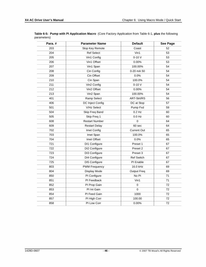
X4 AC Drive User’s Manual Chapter 6: Using Macro Mode / Quick Start
Table 6-5: Pump with PI Application Macro (Core Factory Application from Table 6-1, plus the following parameters)
Para. # Parameter Name Default See Page203 Stop Key Remote Coast 52
204 Ref Select Vin1 53
205 Vin1 Config 0-10 V 53
206 Vin1 Offset 0.00% 53
207 Vin1 Span 100.00% 54
208 Cin Config 0-20 mA 50 54
209 Cin Offset 0.0% 54
210 Cin Span 100.0% 54
211 Vin2 Config 0-10 V 54
212 Vin2 Offset 0.00% 54
213 Vin2 Span 100.00% 54
401 Ramp Select ART-Strt/RS 56
406 DC Inject Config DC at Stop 57
501 V/Hz Select Pump Fxd 59
504 Skip Freq Band 0.2 Hz 60
505 Skip Freq 1 0.0 Hz 60
608 Restart Number 0 64
609 Restart Delay 60 sec 64
702 Imet Config Current Out 65
703 Imet Span 100.0% 65
704 Imet Offset 0.0% 65
721 DI1 Configure Preset 1 67
722 DI2 Configure Preset 2 67
723 DI3 Configure Preset 3 67
724 DI4 Configure Ref Switch 67
725 DI5 Configure PI Enable 67
803 PWM Frequency 16.0 kHz 69
804 Display Mode Output Freq 69
850 PI Configure No PI 71
851 PI Feedback Vin1 71
852 PI Prop Gain 0 72
853 PI Int Gain 0 72
854 PI Feed Gain 1000 72
857 PI High Corr 100.00 72
858 PI Low Corr 0.00% 72
1428D-0607 - 46 - © 2007 TB Wood’s All Rights Reserved

X4 AC Drive User’s Manual Chapter 6: Using Macro Mode / Quick Start
Table 6-6: Vector Application Macro (Core Factory Application from Table 6-1, plus the following parameters)
Para. # Parameter Name Default See Page501 V/Hz Select Vector 59
509 Rated Mtr Volt Model dependent 60
510 Rated Mtr FLA ND rating 60
511 Rated Mtr RPM 1750 rpm 60
514 Motor RS Model dependent 60
515 Power Factor 0.8 60
516 Slip Comp Enable No 61
519 Find Mtr Data Not Active 61
520 Filter FStator 8 mS 61
521 Start Field En No 61
522 Filter Time Slip 100 mS 61
523 Id Percent Read-only 62
524 Iq Percent Read-only 62
803 PWM Frequency 3.0 kHz 69
804 Display Mode Std Display 69
1428D-0607 - 47 - © 2007 TB Wood’s All Rights Reserved

X4 AC Drive User’s Manual Chapter 6: Using Macro Mode / Quick Start
6.4 Quick Start
The following procedure is for operators using simple applications, who would like to get started quickly. Be sure to read and understand all the sections in this chapter before proceeding with these instructions. If you are using remote operators, substitute the speed potentiometer for the UP and DOWN arrows, and the remote Run/Stop switch for the FWD key in the following instructions.
1. Follow all precautions and procedures in “Chapter 3: Receiving and Installation” on page 12.
2. Apply AC power to the input terminals. For about 2 seconds the display will show all segments active. The display then changes to zeros.
3. The factory settings are for keypad-only operation in the forward direction—that is, the REV key is disabled. Press the FWD key, which causes the FWD indicator to illuminate.
4. Press the UP arrow to increase the desired running frequency. When the display gets to 0.1 Hz, the drive starts to produce an output.
5. When the motor starts to turn, check the rotation. If the motor is turning in the wrong direction, press STOP, remove AC power, and wait for all indicators to go out. After the STATUS indicator has gone out, reverse any two of the motor leads at T1/U, T2/V, or T3/W.
6. The X4 drive is preset to run a typical NEMA B 4-pole induction motor to a maximum speed of 60.0 Hz with both acceleration and deceleration times set to 5.0 seconds.
7. Use the Arrow keys to set the proper running speed of the motor and the FWD and STOP keys to control its operation.
IMPROPER EQUIPMENT COORDINATION
Verify that proper voltage is connected to the drive before applying power.
Failure to observe this instruction can result in injury or equipment damage.
CAUTION
MAUVAISE COORDINATION DES APPAREILS
Vérifiez que l’onduleur est raccordée à la bonne tension avant de le mettre sous tension.
Si cette directive n’est pas respectée, cela peut entraîner des blessures corporelles ou des dommages matériels.
ATTENTION
1428D-0607 - 48 - © 2007 TB Wood’s All Rights Reserved

Chapter 7: X4 Parameters
7.1 Introduction
The X4 AC drive incorporates a comprehensive set of parameters that allow you to configure the device to meet the special requirements of your particular application.
Note that pressing the PROG key enters Level 1 programming. Press SHIFT+PROG to enter Level 2 programming. Press ENTER+PROG to show only those parameters that have changed from the factory default values.
This chapter describes the available parameters and the values that may be assigned to them. The parameter summary table at the front of this manual provides a summary of all parameters including their ranges and default values.
7.2 Level 1 Parameters
The most commonly configured X4 parameters are stored in a group named Level 1. This group is easily accessed by pressing the PROG key as described in “Chapter 5: Keypad Operation and Programming” on page 30. The following table lists the parameters in this group; for further information on the parameter, please turn to the indicated page.
Table 7-1: Parameters Available in Level 1 Programming (Factory Macro)
Para. # Parameter NameSee
Page Para. # Parameter NameSee
Page
001 Model Number 50 303 Preset Freq 1 55
010 Last Fault 50 402 Accel Time 1 56
102 Output Freq 51 403 Decel Time 1 56
103 Output Voltage 51 502 Voltage Boost 59
104 Output Current 51 610 Timed OL Select 64
105 Drive Load 51 700 Vmet Config 65
106 Load Torque 51 705 Relay 1 Select 66
107 Drive Temp 51 706 Relay 2 Select 66
111 DC Bus Voltage 51
201 Input Mode 52
202 Rev Enable 52
301 Min Frequency 55
302 Max Frequency 55
1428D-0607 - 49 - © 2007 TB Wood’s All Rights Reserved

X4 AC Drive User’s Manual Chapter 7: X4 Parameters
7.3 Description of Parameters
Table 7-2 lists the X4 parameters in the order in which they appear in the keypad display. For each parameter, the table lists the default value and range and also describes the use of the parameter.
Table 7-2: Description of X4 Parameters (Page 1 of 26)
001 Model Number Read-Only Range: n/aLevel: 1,2
Parameter 001, the Model Number parameter, contains the portion of the X4 model number related to voltage and horsepower. The number format is vvhhf, where vv is the code for the input voltage (19=115 Vac single-phase; 20=230 Vac, three-phase; 40=460 Vac, three-phase; 50=575 Vac, three-phase); hh is horsepower; and f is the fractional part of the horsepower. Example: 20020 = 230 Vac, three-phase, 2.0 HP model.
002 Software Rev Read-Only Range: 0.00-99.99Level: 2
Parameter 002, the Software Revision parameter, displays the software revision that is installed in the drive.
Options: 0.00-99.99
003 Rated Current Read-Only Range: 0.0-200.0 ALevel: 2
Parameter 003, the Rated Current parameter, displays the normal duty current rating of the model of drive.
005 Serial No 1 Read-Only Range: 0-65535Level: 2
Parameter 005, Serial No 1, contains a number that corresponds to the year and week in which the drive was manufactured.
006 Serial No 2 Read-Only Range: 0-65535Level: 2
Parameter 006, Serial No 2, contains a number that determines the number of the drive that was manufactured during the week of Serial No 1.
Options: 0.00-99.99
010 Last Fault Read-Only Range: n/aLevel: 1,2
Parameter 010, Last Fault, lists the fault that occurred most recently.
For more information, refer to Chapter 8, Troubleshooting, beginning on page 83.
025 4th Fault Read-Only Range: n/aLevel: 2
Parameter 025, 4th Fault, lists the fault that occurred 1 before the last fault.
For more information, refer to Chapter 8, Troubleshooting, beginning on page 83.
040 3rd Fault Read-Only Range:n/aLevel: 2
Parameter 040, 3rd Fault, lists the fault that occurred 2 before the last.
For more information, refer to Chapter 8, Troubleshooting, beginning on page 83.
055 2nd Fault Read-Only Range: n/aLevel: 2
Parameter 055, 2nd Fault, lists the fault that occurred 3 before the last.
For more information, refer to Chapter 8, Troubleshooting, beginning on page 83.
070 1st Fault Read-Only Range:n/aLevel: 2
Parameter 070, 1st Fault, lists the fault that occurred 4 before the last.
For more information, refer to Chapter 8, Troubleshooting, beginning on page 83.
1428D-0607 - 50 - © 2007 TB Wood’s All Rights Reserved

X4 AC Drive User’s Manual Chapter 7: X4 Parameters
102 Output Freq Read-Only Range: 0.0 to 400.0 HzLevels 1,2
Parameter 102, the Output Frequency parameter, shows the frequency being applied to the motor connected to the drive (ramp).
103 Output Voltage Read-Only Range: 0 to 600 VLevels 1,2
Parameter 103, the Output Voltage parameter, displays the output voltage of the drive.
104 Output Current Read-Only Range: 0.0 to 200.0 ALevels 1,2
Parameter 104, the Output Current parameter, displays the output current of the drive.
105 Drive Load Read-Only Range: -200.0% to 200.0%Levels 1,2
Parameter 105, the Drive Load parameter, shows the percentage torque of the drive when operating below the knee frequency. It displays Load Torque if the frequency is below FKNEE, and displays Power if above FKNEE.
The output current is measured with the motor power factor applied to an accuracy of ±20%.. The parameter value is positive when the motor is pulling a load (“motoring mode”) and negative when being pulled by a load (“regenerative mode”).
106 Load Torque Read-Only Range: -200.0%-200.0%Levels 1,2
Parameter 106, the Load Torque parameter, displays the load torque of the drive.
107 Drive Temp Read-Only Range: -20.0 to 200.0 °CLevels 1,2
Parameter 107, the Drive Temp parameter, shows the actual temperature of the drive’s heatsink. The drive will fault when the internal temperature reaches 85°C.
108 Total Run Time Read-Only Range: 0.0 - 6553.5 hLevel: 2
Parameter 108, Total Run Time, is a resettable timer for drive operation. To reset the timer, enter 10 in parameter 801, Program Number.
109 Power On Hours Read-Only Range: 0 - 65535 hLevel: 2
Parameter 109, Power On Hours, displays how long the drive has been powered up.
110 Stator Freq Read-Only Range: 0.0-400.0 HzLevel: 2
Parameter 110, Stator Frequency, displays the frequency the drive is applying to the motor stator.
111 DC Bus Voltage Read-Only Range: 0-1000 VdcLevel: 1,2
Parameter 111, DC Bus Voltage, displays the voltage on the DC bus.
115 Drive Power Out Read-Only Range: 0.0%-200.0%Level: 2
This parameter displays the power being output by the drive in terms of drive rating. The measurement is calculated by scaling the Load Torque value by the ratio of Volt-Amps to Rated Volt-Amps, and adjusted by Output Frequency.
Table 7-2: Description of X4 Parameters (Page 2 of 26)
1428D-0607 - 51 - © 2007 TB Wood’s All Rights Reserved

X4 AC Drive User’s Manual Chapter 7: X4 Parameters
201 Input Mode Default = Local only Range: n/aLevels 1,2
Parameter 201, the Input Mode parameter, configures local and remote control of the Start/Stop source and the reference source.
The following data values may be assigned to this parameter:
Parameter Value Run/Stop Control
Local only Local keypad operation only
Remote only Terminal strip operation only
L/R Rem Ref LOCal Keypad Start/Stop and SpeedREMote Keypad Start/Stop, Terminal Strip Speed Reference
L/R Rem Ctl LOCal Keypad Start/Stop and SpeedREMote Keypad Speed Reference, Terminal Strip Start/Stop
L/R Rem Bth LOCal Keypad Start/Stop and SpeedREMote Terminal Strip Start/Stop and Speed Reference
EMOP1 2 4 Terminal strip operation using Increase/Decrease buttons
EMOP21 3 4 Terminal strip operation using Increase/Decrease buttons
LOC/EMOP1 2 4 LOCal Keypad Start/Stop and SpeedREMote Terminal strip operation using Increase/Decrease
LOC/EMOP21 3 4 LOCal Keypad Start/Stop and SpeedREMote Terminal strip operation using Increase/Decrease
Notes:1. Electronic Motor Operated Potentiometer (EMOP): simulates the UP/DOWN arrow keys on keypad using external remote N/O
pushbuttons2. Commanded output frequency returns to the value of parameter 301 (Min Frequency) when the drive is stopped. 3. Commanded output frequency remains at the previous setpoint when the drive is stopped.4. The parameters that set the functions of the designated digital inputs for EMOP must be configured as “EMOP+” and “EMOP–” to
complete the implementation.
202 Rev Enable Default = Forward Range: n/aLevels 1,2
Parameter 202, the Rev Enable parameter, configures whether the REV key on the keypad is functional. If this parameter is configured to “Forward,” then pressing the REV key on the keypad will have no effect. Note that this parameter does not affect terminal strip operation.
The following data values may be assigned to this parameter:
Parameter Value Description
Forward Forward Only, REV key disabledFWD/REV FWD and REV keys enabled
203 Stop Key Remote Default = Coast Range: n/aLevel: 2
Parameter 203, the Stop Key Remote parameter, configures how the Stop key on the keypad will operate when the keypad is not the drive’s control source (terminals, SIO, or SEQ).
The following data values may be assigned to this parameter:
Parameter Value Description
Coast Drive will coast to a stopRamp Drive will ramp to a stop using Decel #1Disabled Stop key will have no function
Table 7-2: Description of X4 Parameters (Page 3 of 26)
1428D-0607 - 52 - © 2007 TB Wood’s All Rights Reserved

X4 AC Drive User’s Manual Chapter 7: X4 Parameters
204-Ref Select Default = Vin1 Range: n/aLevel: 2
Parameter 204, the Ref Select parameter, configures how the reference is determined when the reference source is configured to terminals.
The following data values may be assigned to this parameter:
Parameter Value Description
Vin1 Vin1 terminal (configured by parameter 205)Cin Cin terminal (configured by parameter 208)Vin2 Vin2 terminal (configured by parameter 211)Vin1 6FS Vin1 terminal with 6x pulse train from an X4, WFC, WF2 driveVin1 48FS Vin1 terminal with 48x pulse train from an X4, WFC, WF2 driveVin1+Cin Sum of signal at Vin1 and the signal at CinVin1+Vin2 Sum of signal at Vin1 and the signal at Vin2Vin1-Cin Difference between the signal at Vin and the signal at CinVin1-Vin2 Difference between the signal at Vin and the signal at Vin2Max Input2 Greatest signal between Vin, Vin2 and CinVin1/Cin DI1 Switch between Vin and Cin using a Digital InputVin1/2 DI1 Switch between Vin and Vin2 using a Digital InputVin1/KYP DI1 Switch between Vin and Keypad reference using Digital InputCin/KYP DI1 Switch between Cin and Keypad reference using Digital Input
Notes:1. The parameter that sets the function of the designated digital input must be configured as “Ref Switch” to complete the implementation. 2. The “Max Input” option will compare the inputs of all three analog inputs (Vin1, Vin2, Cin) and take the analog input with the highest
percentage input after span, offset, and inversion is applied.3. When using a 6FS signal, parameter 205 should be set to 0-10V.
205 Vin1 Config Default = 0-10V Range: n/aLevel: 2
Parameter 205, Vin1 Config, selects the type of signal for analog input Vin1. Vin1 can be voltage, current, or pulse train input. This parameter also determines input range, impedance, and characteristics. Use Parameters 206 (Vin1 Offset) and 207 (Vin1 Span) to customize the selected range. The following data values may be assigned to this parameter:
Parameter Value Description
0-10V 0-10Vdc signal0-10V Brk W 0-10Vdc signal with broken wire detection for speed pot operation0-10V I 0-10Vdc signal Inverted0-10V Bipol 0-10Vdc signal
(5Vdc is stop with 0Vdc Full Rev and 10Vdc Full FWD)0-5V 0-5Vdc signal0-5V I 0-5Vdc signal Inverted0-20mA 250 0 to 20 mA current signal with 250 Ohm load0-20mA 250I 0 to 20 mA current signal with 250 Ohm load Inverted4-20mA 250 4 to 20 mA current signal with 250 Ohn load load4-20mA 250I 4 to 20 mA current signal with 250 Ohm load InvertedPT 0-1kHz 0 to 1 kHz pulse trainPT 0-10kHz 0 to 10 kHz pulse trainPT 0-100kHz 0 to 100 kHz pulse train
When the signal range is inverted (that is, the minimum input corresponds to the maximum output, while the maximum input corresponds to the minimum output).
206 Vin1 Offset Default = 0.00% Range: 0.0 to 100.0%Level: 2
Parameter 206, Vin1 Offset, configures the input range (offset) for analog input Vin1 that will affect speed or torque limit functions. It is expressed as a percentage of the maximum value of the input signal.
Note that if the input signal drops below the offset value or if the input signal is lost (if no offset is configured), fault 22 will be generated.
Table 7-2: Description of X4 Parameters (Page 4 of 26)
1428D-0607 - 53 - © 2007 TB Wood’s All Rights Reserved

X4 AC Drive User’s Manual Chapter 7: X4 Parameters
207 Vin1 Span Default = 100% Range: 10.0 to 200.0%Level: 2
Parameter 207, the Vin1 Span parameter, is used to alter the input range (span) of the input signal for analog input Vin1 that will affect speed or torque limit functions. For example, if parameter 205, Vin1 Config, selects the 0 to 10 Vdc input signal, setting this parameter to 50% reduces it to 0 to 5 Vdc.
208-Cin Config Default = 0-20mA 50 Range: n/aLevel 2
Parameter 208, Cin Config, selects the type of signal for analog input Cin. Parameters 209 (Cin Offset) and 210 (Cin Span) may be used to customize the selected range. The following data values may be assigned to this parameter:
Parameter Value Description
4-20mA 50 4 to 20 mA current signal with 50 Ohm load4-20mA 50I 4 to 20 mA current signal with 50 Ohm load Inverted0-20mA 50 0 to 20 mA current signal with 50 Ohn load load0-20mA 50I 0 to 20 mA current signal with 50 Ohm load Inverted
When the signal range is inverted (that is, the minimum input corresponds to the maximum output, while the maximum input corresponds to the minimum output).
209 Cin Offset Default = 0.0% Range: 0.0% to 100.0%Level: 2
Parameter 209, Cin Offset, configures the offset for analog input Cin expressed as a percentage of the maximum value of the input signal. Note that if the input signal drops below the offset value or if the input signal is lost (if no offset is configured), a fault will be generated.
210 Cin Span Default = 100.0% Range: 10.0% to 200.0%
Parameter 210, Cin Span, is used to alter the range of the input signal for analog input Cin. For example, if parameter 208 (Cin Config) selects the 0 to 20 mA input signal, setting this parameter to 50% reduces it to 0 to 10 mA.
211 Vin2 Config Default = 0-10 V Range: n/aLevel: 2
Parameter 211, Vin2 Config, selects the type of signal for analog input Vin2. Parameters 212 (Vin2 Offset) and 213 (Vin2 Span) may be used to customize the selected range. The following data values may be assigned to this parameter:
Parameter Value Description
0-10V 0-10Vdc signal0-10V Brk W 0-10Vdc signal with broken wire detection for speed pot operation0-10V I 0-10Vdc signal inverted0-10V Bipol 0-10Vdc signal (5Vdc is stop with 0Vdc Full REV and 10Vdc Full FWD0-5V 0-5Vdc signal0-5V I 0-5Vdc signal inverted
212 Vin2 Offset Default = 0.0% Range: 0.0% to 100.0%Level: 2
Parameter 212, Vin2 Offset, configures the offset for analog input Vin2 expressed as a percentage of the maximum value of the input signal. Note that if the input signal drops below the offset value or if the input signal is lost (if no offset is configured), a fault will be generated.
213 Vin2 Span Default = 100% Range: 10.0 to 200.0%
Parameter 213, Vin2 Span, is used to alter the range of the input signal for analog input Vin2. For example, if parameter 211 (Vin2 Config) selects the 0 to 10Vdc input signal, setting this parameter to 50% reduces it to 0 to 5Vdc.
214 Vin1 Filter Time Default = 20 ms Range: 0 to 1000 msLevel: 2
This parameter configures the time constant of a filter for the Vin1 analog input. When the parameter value is set to 0 ms, there is no software filtering of the analog input. A value above 0 ms causes the drive to filter the analog signal. Note that long filter times will create a delay in the drive response to signal changes.
Table 7-2: Description of X4 Parameters (Page 5 of 26)
1428D-0607 - 54 - © 2007 TB Wood’s All Rights Reserved

X4 AC Drive User’s Manual Chapter 7: X4 Parameters
215 Cin Filter Time Default = 20 ms Range: 0 to 1000 msLevel: 2
This parameter configures the time constant of a filter of the Cin analog input. When the parameter value is set to 0 ms, there is no software filtering of the analog input. A value above 0 ms causes the drive to filter the analog signal. Note that long filter times will create a delay in the drive response to signal changes.
216 Vin2 Filter Time Default = 20 ms Range: 0 to 1000 msLevel: 2
This parameter configures the time constant of a filter for the Vin2 analog input. When the parameter value is set to 0 ms, there is no software filtering of the analog input. A value above 0 ms causes the drive to filter the analog signal. Note that long filter times will create a delay in the drive response to signal changes.
217 Trim Ref Enable Default = 0 Range: n/aLevel: 2
This parameter enables or disables trimming of the drive reference by an analog input and selects which analog input will perform the trimming function.
Speed Reference = Main reference + (Trim % Factor) * value of Parameter 217 * Max Frequency / 100%
Parameter Value Description
Disabled No trimming of drive referenceVin1 Value of Vin1 will be used in the calculation aboveVin2 Value of Vin2 will be used in the calculation aboveCin Value of Cin will be used in the calculation aboveFxd Trim % Value of Fxd Trim % will be used
Drive Reference = Drive Reference + (Trim % Factor) * Max Frequency / 100%
Note that setting a parameter for a Bipolar input value allows trimming both positive and negative around the reference value.
218 Trim % Factor Default = 0.0%Range: -100.0% to +100.0%
Level 2
This parameter determines the percentage of the analog input signal selected in Parameter 217, Trim Ref Enable, that will affect the reference signal.
301 Min Frequency Default = 0.0% Range: 0.0-Max Freq
Parameter 301, Minimum Frequency, configures the minimum frequency output of the drive. This parameter governs the minimum frequency when operating from the keypad or from an analog input. The preset speeds can be set lower than the minimum frequency in parameter 301.
302 Max Frequency Default: 60 Hz Range: 0.0 to 400.0 Hz
Parameter 302, the Maximum Frequency parameter, configures the maximum frequency output of the drive.
303 Preset Freq 1 (Jog Ref)304 Preset Freq 2305 Preset Freq 3306 Preset Freq 4307 Preset Freq 5308 Preset Freq 6
Default: 5 HzDefault: 10 HzDefault: 20 HzDefault: 30 HzDefault: 40 HzDefault: 50 Hz
Range: 0.0-Max FreqLevels 1,2 for 303
Level 2 for 304-308
These parameters configure six preset speeds in addition to the normal reference speed of the drive (as defined by parameters 201 (Input Mode) and 204 (Ref Select) and the maximum frequency of the drive (as set with parameter 302, Max Frequency). Thus, in effect, you may choose to operate the drive at up to eight different speeds.
The eight speeds are selected by a combination of three digital inputs (PS1, PS2, PS3). A wiring scheme for utilizing preset speeds is provided on page 28 along with a truth table showing what combination of inputs results in the selection of which speeds.
Note that parameter Parameter 303 (Preset Freq1) also serves as the reference frequency for jogging.
Table 7-2: Description of X4 Parameters (Page 6 of 26)
1428D-0607 - 55 - © 2007 TB Wood’s All Rights Reserved

X4 AC Drive User’s Manual Chapter 7: X4 Parameters
309 Cut-Off Freq Default: 0.0 HzRange: 0.0 to 5.0 Hz
Level 2
This parameter sets the point where the drive no longer attempts to spin the motor. The range of this parameter is 0.0-5.0 Hz. When the parameter is configured to a value of 0.0 Hz, the drive will operate with no Cut-off Frequency. If the function is enabled, the drive will be able to ramp up through the cut-off frequency range, as in normal operation. If the speed command falls below the cut-off frequency, the drive stops “gating” the outputs and coasts down to zero speed. The keypad display will indicate Zero Speed, and the Forward or Reverse LED will be lit depending on the command. When the reference returns to a value greater than the cut-off frequency, the drive will ramp from 0.0 Hz to the reference frequency.
401 Ramp Select Default: ART DI Range: n/aLevel: 2
The Ramp Select parameter configures when the alternate ramps of the drive will be active and whether the drive ramps to stop, or coasts to stop. The following data values may be assigned to this parameter:
Parameter Value Type of Ramp Ramp Configured by:
ART-DI Ramp-to-Stop 402 (Accel Time 1) and 403 (Decel Time 1)
ART-F/R Ramp-to-Stop Running forward: 402 (Accel Time 1) and 403 (Decel Time 1)Running reverse: 404 (Accel Time 2) and 405 (Decel Tiime 2)
ART-Frq Ramp-to-Stop If the output frequency is less than preset frequency parameter 308 (Preset Freq 6), the active ramp is set by 402 Accel Time 1 and 403 Decel Time 1. If the output frequency is equal to or greater than 308 (Preset Freq 6), the active ramp is set by 404 (Accel Time 2) and 405 (Decel Time 2).
ART-Strt/RS Ramp-to-Stop This setting uses the Alternate Ramp for Acceleration (parameter 404) to the set speed, then uses the Main ramps (parameters 402 and 403) when the speeds are adjusted. The drive will revert to the Alternate Decel ramp (parameter 405) when a Stop command is given.
S-Curve Ramp-to-Stop The drive uses 402 (Accel Time 1) and 403 (Decel Time 1) for total time and 414 as the S Ramp Rounding value. The amount of rounding is the same for that start and stop of the ramp time.
ART-DI CTS Coast-to-Stop Same as ART-DI but with Coast-to-Stop
ART-F/R CTS Coast-to-Stop Same as ART-F/R but with Coast-to-Stop
ART-Frq CTS Coast-to-Stop Same as ART-Frq but with Coast-to-Stop
ART-Str/CS Coast-to-Stop Same as ART-Strt but with Coast-to-Stop
S-Curve CTS Coast-to-Stop Same as S-Curve but with Coast-to-Stop
402 Accel Time 1 Default: 5.0 s Range: 0.1 to 3200.0 sLevels 1,2
This parameter configures the default length of time to accelerate from 0 Hz to the value of parameter 302 (Max Frequency). This acceleration ramp is selected by parameter 401 (Ramp Select).
Note that extremely short acceleration times may result in nuisance fault trips.
403 Decel Time 1 Default: 5.0 s Range: 0.1 to 3200.0 sLevels 1,2
This parameter configures the default length of time to decelerate from the value of parameter 302 (Max Frequency) to 0 Hz. The deceleration ramp is selected by Parameter 401 (Ramp Select).
Note that extremely short deceleration times may result in nuisance fault trips or may require an external dynamic brake or regen current limit.
404 Accel Time 2 Default: 3.0 s Range: 0.1 to 3200.0 sLevel 2
This parameter provides an alternate ramping time for the drive when accelerating, configuring the length of time to accelerate from 0 Hz to the value of parameter 302 (Max Frequency). This acceleration ramp is selected by parameter 401 (Ramp Select) or Sequencer Configuration.
Note that extremely short acceleration times may result in nuisance fault trips.
Table 7-2: Description of X4 Parameters (Page 7 of 26)
1428D-0607 - 56 - © 2007 TB Wood’s All Rights Reserved
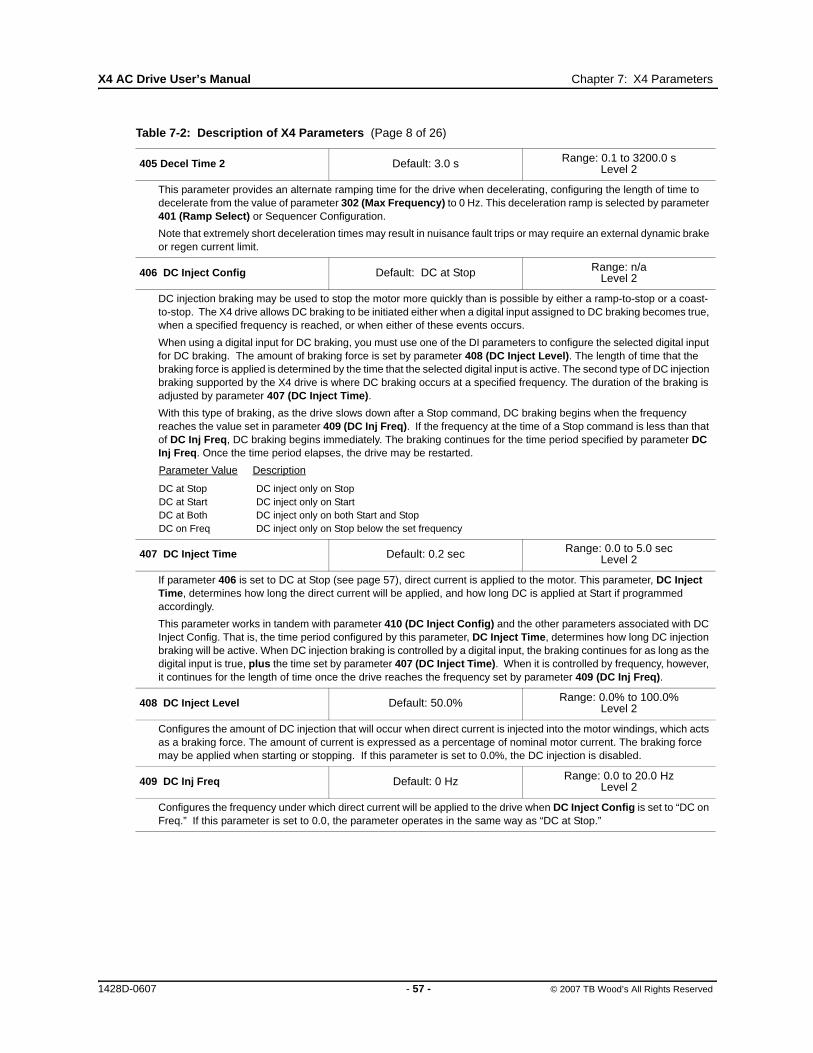
X4 AC Drive User’s Manual Chapter 7: X4 Parameters
405 Decel Time 2 Default: 3.0 s Range: 0.1 to 3200.0 sLevel 2
This parameter provides an alternate ramping time for the drive when decelerating, configuring the length of time to decelerate from the value of parameter 302 (Max Frequency) to 0 Hz. This deceleration ramp is selected by parameter 401 (Ramp Select) or Sequencer Configuration.
Note that extremely short deceleration times may result in nuisance fault trips or may require an external dynamic brake or regen current limit.
406 DC Inject Config Default: DC at Stop Range: n/aLevel 2
DC injection braking may be used to stop the motor more quickly than is possible by either a ramp-to-stop or a coast-to-stop. The X4 drive allows DC braking to be initiated either when a digital input assigned to DC braking becomes true, when a specified frequency is reached, or when either of these events occurs.
When using a digital input for DC braking, you must use one of the DI parameters to configure the selected digital input for DC braking. The amount of braking force is set by parameter 408 (DC Inject Level). The length of time that the braking force is applied is determined by the time that the selected digital input is active. The second type of DC injection braking supported by the X4 drive is where DC braking occurs at a specified frequency. The duration of the braking is adjusted by parameter 407 (DC Inject Time).
With this type of braking, as the drive slows down after a Stop command, DC braking begins when the frequency reaches the value set in parameter 409 (DC Inj Freq). If the frequency at the time of a Stop command is less than that of DC Inj Freq, DC braking begins immediately. The braking continues for the time period specified by parameter DC Inj Freq. Once the time period elapses, the drive may be restarted.
Parameter Value Description
DC at Stop DC inject only on StopDC at Start DC inject only on StartDC at Both DC inject only on both Start and StopDC on Freq DC inject only on Stop below the set frequency
407 DC Inject Time Default: 0.2 sec Range: 0.0 to 5.0 secLevel 2
If parameter 406 is set to DC at Stop (see page 57), direct current is applied to the motor. This parameter, DC Inject Time, determines how long the direct current will be applied, and how long DC is applied at Start if programmed accordingly.
This parameter works in tandem with parameter 410 (DC Inject Config) and the other parameters associated with DC Inject Config. That is, the time period configured by this parameter, DC Inject Time, determines how long DC injection braking will be active. When DC injection braking is controlled by a digital input, the braking continues for as long as the digital input is true, plus the time set by parameter 407 (DC Inject Time). When it is controlled by frequency, however, it continues for the length of time once the drive reaches the frequency set by parameter 409 (DC Inj Freq).
408 DC Inject Level Default: 50.0% Range: 0.0% to 100.0%Level 2
Configures the amount of DC injection that will occur when direct current is injected into the motor windings, which acts as a braking force. The amount of current is expressed as a percentage of nominal motor current. The braking force may be applied when starting or stopping. If this parameter is set to 0.0%, the DC injection is disabled.
409 DC Inj Freq Default: 0 Hz Range: 0.0 to 20.0 HzLevel 2
Configures the frequency under which direct current will be applied to the drive when DC Inject Config is set to “DC on Freq.” If this parameter is set to 0.0, the parameter operates in the same way as “DC at Stop.”
Table 7-2: Description of X4 Parameters (Page 8 of 26)
1428D-0607 - 57 - © 2007 TB Wood’s All Rights Reserved

X4 AC Drive User’s Manual Chapter 7: X4 Parameters
410 DB Config Default: DB Internal Range: 0-2Level 2
Determines whether an external or internal dynamic brake is utilized or disabled. The drive provides an internal dynamic brake (DB) to assist in stopping. If desired, an external resistor can be connected to DB and B+ for additional capacity. (Note: Size 0 models cannot have an external brake added.)
The following data values may be assigned to this parameter:
Parameter Value Description
DB Internal Internal dynamic braking activeDB External External dynamic braking activeNo Dyn Brk Dynamic braking circuit disabledInt-ARCTIC When DB Config is configured to “Int-ARCTIC,” dynamic braking becomes active if the drive temperature
drops below -7 degrees C. When the DB becomes active, an “ARCTIC Mode” warning flashes on the keypad. If the drive drops below -10 degrees C, the drive will be disabled and not allowed to run. The keypad will indicate a “Not enabled” state at this point. If the drive heats up after being below -10 degrees C, the drive must meet the following criteria before operating again:a) Drive temperature must be above -9 degrees C, andb) Drive temperature must stay above -9 degrees C until a time period has elapsed. The time period is
dependent on how far below -10 degrees C the drive was. Each degree below -10 degrees C adds another 4 minutes before restart.
414 S Ramp Rounding Default: 25% Range: 1-100%Level 2
This parameter is used to define the amount of rounding or S-curve to the Accel and Decel ramp. The amount of rounding is split evenly between the beginning and the end of the ramp. A value of 1% would mean that the rounding of the ramp is near linear. A value of 50% would have 25% rounding at the start of the ramp and 25% at the end of the ramp.
Table 7-2: Description of X4 Parameters (Page 9 of 26)
MOTOR OVERHEATING
Do not use DC injection braking as a holding brake, or excessive motor heating may result.
Failure to observe this instruction can result in equipment damage.
CAUTION
SURCHAUFFE DU MOTEUR
N’utilisez pas le fraingres CC comme frein de maintien car cela peut entraîner une surchauffe excessive du moteur.
Si cette directive n’est pas respectée, cela peut entraîner des dommages matériels.
ATTENTION
1428D-0607 - 58 - © 2007 TB Wood’s All Rights Reserved
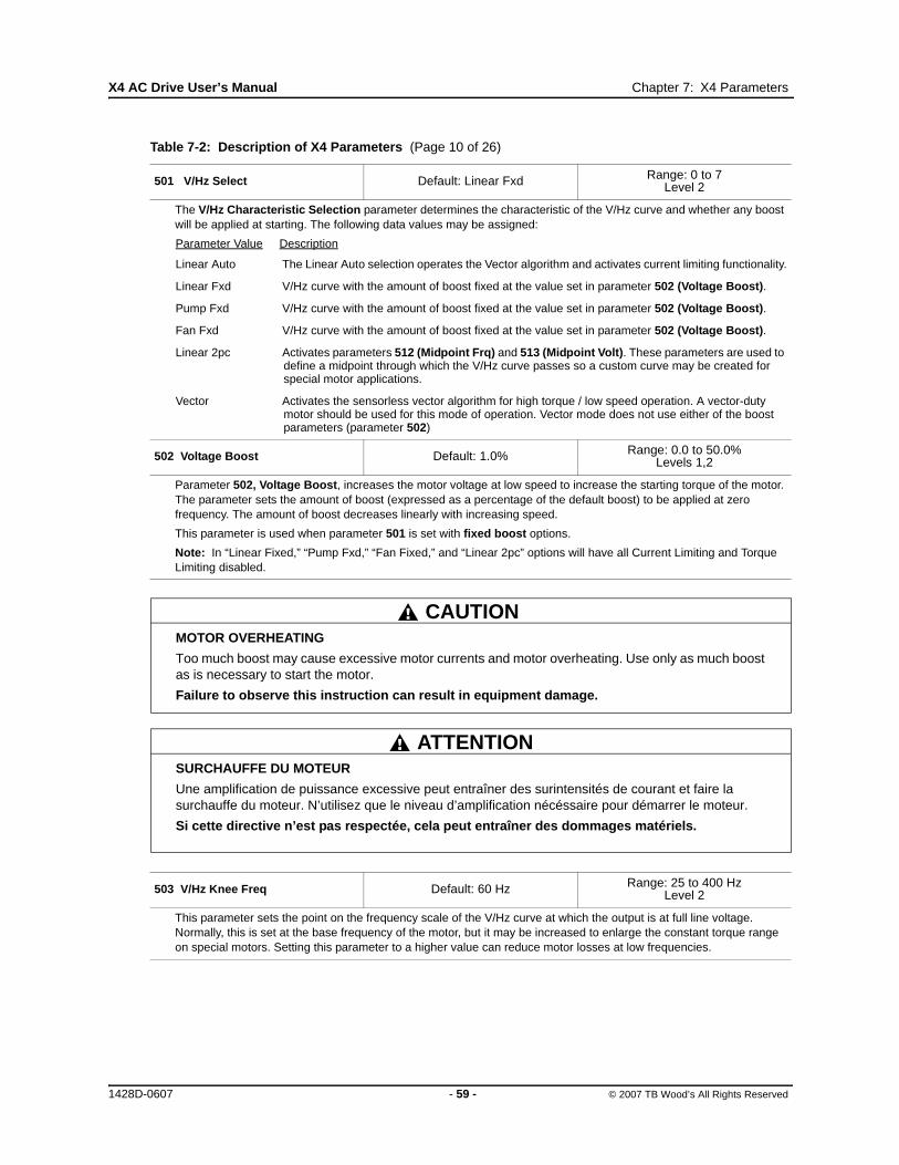
X4 AC Drive User’s Manual Chapter 7: X4 Parameters
501 V/Hz Select Default: Linear Fxd Range: 0 to 7Level 2
The V/Hz Characteristic Selection parameter determines the characteristic of the V/Hz curve and whether any boost will be applied at starting. The following data values may be assigned:
Parameter Value Description
Linear Auto The Linear Auto selection operates the Vector algorithm and activates current limiting functionality.
Linear Fxd V/Hz curve with the amount of boost fixed at the value set in parameter 502 (Voltage Boost).
Pump Fxd V/Hz curve with the amount of boost fixed at the value set in parameter 502 (Voltage Boost).
Fan Fxd V/Hz curve with the amount of boost fixed at the value set in parameter 502 (Voltage Boost).
Linear 2pc Activates parameters 512 (Midpoint Frq) and 513 (Midpoint Volt). These parameters are used to define a midpoint through which the V/Hz curve passes so a custom curve may be created for special motor applications.
Vector Activates the sensorless vector algorithm for high torque / low speed operation. A vector-duty motor should be used for this mode of operation. Vector mode does not use either of the boost parameters (parameter 502)
502 Voltage Boost Default: 1.0% Range: 0.0 to 50.0%Levels 1,2
Parameter 502, Voltage Boost, increases the motor voltage at low speed to increase the starting torque of the motor. The parameter sets the amount of boost (expressed as a percentage of the default boost) to be applied at zero frequency. The amount of boost decreases linearly with increasing speed.
This parameter is used when parameter 501 is set with fixed boost options.
Note: In “Linear Fixed,” “Pump Fxd,” “Fan Fixed,” and “Linear 2pc” options will have all Current Limiting and Torque Limiting disabled.
503 V/Hz Knee Freq Default: 60 Hz Range: 25 to 400 HzLevel 2
This parameter sets the point on the frequency scale of the V/Hz curve at which the output is at full line voltage. Normally, this is set at the base frequency of the motor, but it may be increased to enlarge the constant torque range on special motors. Setting this parameter to a higher value can reduce motor losses at low frequencies.
Table 7-2: Description of X4 Parameters (Page 10 of 26)
MOTOR OVERHEATING
Too much boost may cause excessive motor currents and motor overheating. Use only as much boost as is necessary to start the motor.
Failure to observe this instruction can result in equipment damage.
CAUTION
SURCHAUFFE DU MOTEUR
Une amplification de puissance excessive peut entraîner des surintensités de courant et faire la surchauffe du moteur. N’utilisez que le niveau d’amplification nécéssaire pour démarrer le moteur.
Si cette directive n’est pas respectée, cela peut entraîner des dommages matériels.
ATTENTION
1428D-0607 - 59 - © 2007 TB Wood’s All Rights Reserved

X4 AC Drive User’s Manual Chapter 7: X4 Parameters
504 Skip Freq Band Default: 0.2 Hz Range: 0.2 to 20.0 HzLevel 2
To reduce mechanical resonances in a drive system, the drive may be configured to “skip” certain frequencies. Once configured, the drive will accelerate or decelerate through the prohibited frequency band without settling on any frequency in the band.
The X4 AC drive provides the capability to configure four prohibited frequency bands. Parameter 504 (Skip Freq Band), the Skip Frequency Band parameter, sets the width of the band above and below each of the prohibited frequencies set in parameters 505, 506, 507, and 508 (Skip Freq 1,2,3, 4).
For example, if this parameter is set to its default value of 1 Hz and parameter 505 (Skip Freq 1) is set to 20 Hz, a skip band from 19 to 21 Hz is established.
505 Skip Freq 1506 Skip Freq 2507 Skip Freq 3508 Skip Freq 4
Default: 0.0 Hz Range: Min Freq-Max FreqLevel 2
As discussed in the description of parameter 504 (Skip Freq Band), the drive may be configured to skip certain frequencies. These three parameters set the center of the three skip frequency bands (with the width of each band being twice the value of parameter 504 — an equal amount above and below the skip frequency).
For example, if parameter 504 is set to 2.5 Hz and parameter 508 (Skip Freq 4) is set to 55 Hz, a skip band from 52.5 to 57.5 Hz is established.
509 Rated Mtr Volt Default: Model dependent Range: 100 V - 690 VLevel 2, Macro
The Rated Motor Voltage parameter configures the rated motor voltage, and allows a user to enter the rated voltage from the motor nameplate to provide optimal control and protection. This is usually the amount of voltage delivered to the motor terminals at the setting of 503 (V/Hz Knee Freq).
510 Rated Mtr FLA Default: ND Rating Range: 50% - 200% of ND ratingLevel 2, Macro
The Rated Motor FLA parameter allows a user to enter the rated FLA from the motor nameplate to provide optimal control and protection. This parameter should be configured to the value on the nameplate of the motor, as that value is used in calculating the percentage of current at which the drive is operating.
For information on motor timed overload operation, and how Parameter 510 works with it, see page 64.
511 Rated Mtr RPM Default: 1750 rpm Range: 0-24000 rpmLevel 2, Macro
This parameter replaces the slip compensation parameter setting of the drive so the user does not need to calculate it.
512 Midpoint Freq Default: 60.0 Hz Range: 0.0 Hz-V/Hz Knee FreqLevel 2
When parameter 501, V/Hz Select, is configured to “Linear 2pc,” this parameter, together with parameter 513, Midpoint Volt, defines an additional point in the V/Hz characteristic.
513 Midpoint Volt Default: 100.0% Range: 0.0%-100.0%Level 2
When parameter 501, V/Hz Select, is configured to “Linear 2pc,” this parameter, along with parameter 512, Midpoint Freq, defines an additional point in the V/Hz characteristic.
514 Motor RS Default: Model dependent Range: 0.00-655.35 OhmsLevel 2, Macro
This parameter allows direct entry of the Stator Resistance (Rs) of the motor for better vector performance. The motor manufacturer can provide this information.
515 Power Factor Default: 0.80 Range: 0.50 - 1.00Level 2, Macro
This parameter allows direct entry of the motor’s power factor for better vector performance. The motor manufacturer can provide this information.
Table 7-2: Description of X4 Parameters (Page 11 of 26)
1428D-0607 - 60 - © 2007 TB Wood’s All Rights Reserved

X4 AC Drive User’s Manual Chapter 7: X4 Parameters
516 Slip Comp Enable Default: No Range: n/aLevel 1,2
The following data values may be assigned to this parameter:
Parameter Value Description
No No Slip Compensation enabledYes Slip Compensation enabled
Parameter 516 permits activation of slip compensation for better speed regulation. The motor rated speed must be entered into parameter 511 (Rated Mtr RPM) for best results.
517 Single Phase Default: No Range: n/aLevel 2
The following data values may be assigned to this parameter:
Parameter Value Description
No No single phase input operation. Phase loss engaged.Yes Single phase operation. No phase loss.
519 Find Mtr Data Default: Not active Range: n/aMacro
This parameter activates the drive’s ability to measure the stator resistance of the attached motor. The automatic stator resistance measurement can be performed either through the keypad or through the serial link. See “Measuring Stator Resistance (RS Measurement)” on page 37 for more information about this parameter. The following data values may be assigned:
Parameter Value Description
Not Active No stator RS measurement.Motor RS Automatic RS measurement using macro procedure.
520 Filter FStator Default: 8 ms Range: 1 - 100 msLevel 2
This parameter filters the stator frequency applied to the motor, which can help tune the acceleration behavior of the motor. This is particularly helpful when using short ramps and operating the motor at a frequency above the “V/Hz Knee Freq” (parameter 503) value (field weakening area). Lower values allow dynamic currents to be produced, but with greater peaks. This could produce unstable states in the field weakening area. Low values for this parameter can cause overcurrent faults while accelerating to frequencies over the Knee Frequency. Higher values allow the drive to run more smoothly at frequencies over the Knee Frequency and protect the drive against overcurrents--often the case when using special motors or spindle drives.
521 Start Field En Default: No Range: n/aLevel 2
Parameter Value Description
No The shaft will begin rotating after receiving a Start command, without delay. If the application has heavy load conditions or short ramp times, this setting can produce very large starting currents, to overcome the inertia of the system. This may produce nuisance trips when starting.
Yes The shaft will begin rotating after receiving a Start command, with delay. During this delay, the drive is building up the magnetic field in the motor. This allows the drive to start in vector mode with less starting current.
522 Filter Time Slip Default: 100 ms Range: 10 - 1000 msLevel 2
This parameter filters the slip frequency applied to the motor, which can help improve the dynamic response of the drive. This parameter produces the following results based on the parameter value:
If the parameter is configured to 100 ms, the drive will produce stable conditions to a change in load, in most cases.
If the parameter is configured to less than 100 ms, the drive will be able to react quickly to a change in load, but may over-compensate its reaction to the load.
If the parameter is configured to greater than 100 ms, the drive will react very slowly to a change in load and will need a longer time to compensate for the difference between the setpoint and the actual frequency.
Table 7-2: Description of X4 Parameters (Page 12 of 26)
1428D-0607 - 61 - © 2007 TB Wood’s All Rights Reserved

X4 AC Drive User’s Manual Chapter 7: X4 Parameters
523 Id Percent Default: Read-only Range: 0 - 200%Level 2
This parameter shows the Flux producing current (as a percentage of motor rated current) that is being applied to the drive.
524 Iq Percent Default: Read-only Range: 0 - 200%Level 2
This parameter shows the Torque producing current (as a percentage of motor rated current) that is being applied to the drive.
525 Power Fail Config Default: CTS No Msg Range: n/aLevel 2
This parameter can be used to define how the drive responds to an undervoltage operation when parameter 502 is set for Vector or Linear Auto mode. The following data values may be assigned to this parameter:
Parameter Value Description
CTS No Msg The drive will coast to a stop when an undervoltage condition (power-down) is detected.
Coast Stop The drive will coast to a stop when an undervoltage condition (power-down) is detected. In this mode, however, the drive will generate an undervoltage fault, which will be registered in the fault log.
Ramp Down With this setting, if power is lost, the drive ramps the motor down at a decel rate of Decel 1. When the drive is fully ramped down, the drive will generate an undervoltage fault. If power is restored, the drive will continue to ramp to a stop and will fault.
Quick Ramp Same as Ramp Down, except the shorter ramp time (Decel 1 or Decel 2) will be used.
Controlled With this setting, if power is lost, the drive decelerates the motor, trying to regulate the bus voltage to the undervoltage level. If power is restored, the drive accelerates to the command frequency without faulting. If the drive reaches the stopped condition, it will generate an undervoltage fault.
ContrNoMsg Same as Controlled, but without generating an undervoltage fault.
Note: Current limit is only available when Parameter 502 is set to Linear Auto. If Parameter 502 is set to Vector, then the Current Limiting values will actually be Torque Limiting values.
526 UV Ride-Thru En Default: w/ LVT Range: n/aLevel 2
This parameter allows the function to disable either (a) undervoltage ride-through or (b) continuous Line Voltage Tracking (LVT) that produces dynamic Undervoltage Ride-Thru Thresholds. The following data values may be assigned to this parameter:
Parameter Value Description
Disabled This turns off the Undervoltage Ride-Thru function.
w/ LVT This enables the standard Ride-Thru algorithm in the V/Hz modes and allows the choice of algorithm in the Linear Auto and Vector modes.
w/o LVT This option operates in the same way as “w/ LVT” except that the Line Voltage Tracker function of the Undervoltage Ride-Thru is not active. The Line Voltage will be estimated on powering up the drive.
Table 7-2: Description of X4 Parameters (Page 13 of 26)
1428D-0607 - 62 - © 2007 TB Wood’s All Rights Reserved

X4 AC Drive User’s Manual Chapter 7: X4 Parameters
600 Current Lim Sel Default: Fixed Lvls Range: n/aLevel 2
The X4 drive provides a Current Limit feature. With this feature enabled, the drive’s frequency is automatically reduced when operating in motoring mode to keep the measured torque within limits. When operating in regenerative mode, the output frequency can be automatically increased for the same reason. In addition to the current limit parameters that activate the Current Limit mode, more current limit parameters are available to adjust the drive’s response to the load demands. The following data values may be assigned to this parameter:
Parameter Value Description
Fixed Lvls The fixed levels set in parameters 601, 602, 603 and 604 determine the current limit in each of the four quadrants of operation.
Vin2 Vin2 analog input sets the current limit value, range 0-200%
Cin Cin analog input sets the current limit value, range 0-200%
Vin2 Motor Vin2 analog input sets the motoring current limit value, range 0-200%
Cin Motor Cin analog input sets the motoring current limit value, range 0-200%
Vin2 F-Mtr Vin2 analog input sets the FWD motoring current limit value, range 0-200%
Cin F-Motor Cin analog input sets the FWD motoring current limit value, range 0-200%
Note: Current limit is only available when Parameter 502 is set to Linear Auto. If Parameter 502 is set to Vector, then the Current Limiting values will actually be Torque Limiting values.
601 Cur Lim Mtr Fwd Default: 120% Range: 5-150%Level 2
This parameter sets the current limiting point when the drive is in motoring mode in the forward direction. The limit is expressed as a percentage of the current capacity of the drive.
602 Cur Lim Mtr Rev Default: 120% Range: 5-150%Level 2
This parameter sets the current limiting point when the drive is in motoring mode in the reverse direction. The limit is expressed as a percentage of the current capacity of the drive.
603 Cur Lim Reg Fwd Default: 80% Range: 5-150%Level 2
This parameter sets the current limiting point when the drive is in regenerative mode in the forward direction. The limit is expressed as a percentage of the current capacity of the drive.
604 Cur Lim Reg Rev Default: 80% Range: 5-150%Level 2
This parameter sets the current limiting point when the drive is in regenerative mode in the reverse direction. The limit is expressed as a percentage of the current capacity of the drive.
605 Cur Lim Freq Default: 3.0 Hz Range: 0.0 - 400.0 HzLevel 2
This parameter sets the frequency where current limit becomes active. This value will also be the frequency point the drive will decelerate the motor to during Motoring Current Limit.
606 Ramp Time CL Default: 1.0 sec Range: 0.1-3200.0 secLevel 2
This parameter determines the ramp rate when the drive enters Current Limit, and defines the ramping rate of the drive when in a current limiting mode. If the drive is in regenerative current limit, it is an acceleration time. If the drive is in motoring current limit, it is a deceleration time.
607 Cur Lim Minimum Default: 10% Range: 0 - 50%Level 2
This parameter limits the lowest amount of current (or Torque) limiting that can occur when the limit threshold is determined by an analog input.
Table 7-2: Description of X4 Parameters (Page 14 of 26)
1428D-0607 - 63 - © 2007 TB Wood’s All Rights Reserved

X4 AC Drive User’s Manual Chapter 7: X4 Parameters
608 Restart Number609 Restart Delay
Default: 0Default: 60 sec
P608 Range: 0-8P609 Range: 0-60 secLevel 2
You may configure the drive to attempt to re-start a specified number of times after certain faults occur. Chapter 8 lists all faults and notes which ones may be reset automatically.
The number of attempts at re-starting is set with parameter 608 (Restart Number). A value of 0 prevents the drive from attempting a re-start). The time duration that must elapse between re-start attempts is set with parameter 609 (Restart Delay). The type of start to be attempted is set with parameter 802 (Start Options); see page 69).
If the number of attempted re-starts is exceeded, the drive will trip with a fault and will stop operating. Resetting the fault can result in instant starting. (See page 83 for more information on faults and troubleshooting.)
Note that for 2-wire operation, the FWD or REV terminal must still be active for the drive to attempt a re-start.
Also note that the counter for attempted re-starts will not reset to zero until ten minutes after a successful re-start.
610 Timed OL Select Default: Std Ind 60s Range: 0-7Level 2
Two parameters in the X4 work together to configure how the motor timed overload operates: Parameter 510 (Rated Mtr FLA) and Parameter 610 (Timed OL Select).
Parameter 510 (Rated Mtr FLA) should be configured to the value on the nameplate of the motor. This value is used in calculating the percentage of current at which the drive is operating.
Set parameter 610 to one of the following data values to configure the desired overload characteristic:
Options Trip Time Motor Type Motor ClassStd Ind Shp 0 sec Standard Induction N/AStd Ind 30s 30 sec Standard Induction 1Std Ind 60s 60 sec Standard Induction 2Std Ind 5mn 300 sec Standard Induction 10In Duty Shp 0 sec Inverter Duty N/AIn Duty 30s 30 sec Inverter Duty 1In Duty 60s 60 sec Inverter Duty 2In Duty 5mn 300 sec Inverter Duty 10
Parameter 610 (Timed OL Select) determines the graph of Trip (Fault) Time vs. Percent Current that is used by the Motor TOL functionality. This protective feature is speed-dependent to handle standard induction motors whose cooling is limited by the shaft-mounted fan. Blower-cooled motors and most inverter-duty motors do not have this limitation.
613 Max Regen Ramp Default: 300% Range: 100 - 1000%Level 2
This parameter operates as a percentage of the longest ramp time. This time then defines the amount of time a deceleration to stop can take without causing a “Regen Timeout” fault. For example, if “Decel Time 1” is 5.0 seconds, “Decel Time 2” is 10.0 seconds, and “Max Regen Ramp” is 300%, a deceleration to stop that takes more than 30 seconds will cause a “Regen Timeout” fault in the drive.
Table 7-2: Description of X4 Parameters (Page 15 of 26)
UNINTENDED EQUIPMENT ACTION
Ensure that automatic re-starting will not cause injury to personnel or damage to equipment.
Failure to observe this instruction can result in serious injury or equipment damage.
WARNING
ACTIONNEMENT INVOLONTAIRE DE L’APPAREIL
Assurez-vous qu’un redémarrage automatique n’entraînera ni des blessures au personnel ni des dommages matériels.
Si cette directive n’est pas respectée, cela peut entraîner des blessures graves ou des dommages matériels.
AVERTISSEMENT
1428D-0607 - 64 - © 2007 TB Wood’s All Rights Reserved

X4 AC Drive User’s Manual Chapter 7: X4 Parameters
700 Vmet Config Default: Freq Out Range: n/aLevels 1,2
This parameter configures the analog signal that will be applied to the Vmet output pin.
The following data values may be assigned to this parameter:
Para. Value Description Range Limit
Freq Out Output frequency of the drive Parameter max freq.
Voltage Out Voltage being supplied to the motor Rated motor voltage
Current Out Current being supplied to the motor 200% of drive rating
Drive Load Calculated percentage of drive rating 200% of drive rating
Drive Temp Calculation of total drive temp rating 100% of unit temp rating
Stator Freq Commanded frequency 100% of input config
Power Out Calculated power output of drive 250% of drive rating
PI Fback Allows the analog output to producea signal in proportion to the PI feedbackreceived.
701 Vmet Span Default: 100% Range: 0.0%-200.0%Level 2
This parameter sets the span of the Vmet analog output.
702 Imet Config Default: Drive Load Range: n/aLevel 2
This parameter configures the analog signal that will be applied to the Imet output pin. The following data values may be assigned to this parameter:
Para. Value Description Range LimitFreq Out Output frequency of the drive Parameter max freq.Voltage Out Voltage being supplied to the motor Rated motor voltageCurrent Out Current being supplied to the motor 200% of drive ratingDrive Load Calculated percentage of drive rating 200% of drive ratingDrive Temp Calculation of total drive temp rating 100% of unit temp ratingStator Freq Commanded frequency 100% of input configPower Out Calculated power output of drive 250% of drive ratingPI Fback Allows the analog output to produce
a signal in proportion to the PI feedbackreceived.
703 Imet Span Default: 100% Range: 0.0%-200.0%Level 2
This parameter sets the span of the Imet analog output.
704 Imet Offset Default: 0.0% Range: 0.0%-90.0%Level 2
This parameter sets the offset of the Imet analog output.
Table 7-2: Description of X4 Parameters (Page 16 of 26)
1428D-0607 - 65 - © 2007 TB Wood’s All Rights Reserved
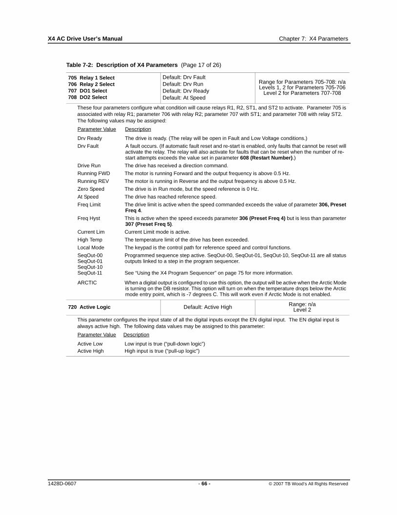
X4 AC Drive User’s Manual Chapter 7: X4 Parameters
705 Relay 1 Select 706 Relay 2 Select707 DO1 Select708 DO2 Select
Default: Drv FaultDefault: Drv RunDefault: Drv ReadyDefault: At Speed
Range for Parameters 705-708: n/aLevels 1, 2 for Parameters 705-706
Level 2 for Parameters 707-708
These four parameters configure what condition will cause relays R1, R2, ST1, and ST2 to activate. Parameter 705 is associated with relay R1; parameter 706 with relay R2; parameter 707 with ST1; and parameter 708 with relay ST2. The following values may be assigned:
Parameter Value Description
Drv Ready The drive is ready. (The relay will be open in Fault and Low Voltage conditions.)
Drv Fault A fault occurs. (If automatic fault reset and re-start is enabled, only faults that cannot be reset will activate the relay. The relay will also activate for faults that can be reset when the number of re-start attempts exceeds the value set in parameter 608 (Restart Number).)
Drive Run The drive has received a direction command.
Running FWD The motor is running Forward and the output frequency is above 0.5 Hz.
Running REV The motor is running in Reverse and the output frequency is above 0.5 Hz.
Zero Speed The drive is in Run mode, but the speed reference is 0 Hz.
At Speed The drive has reached reference speed.
Freq Limit The drive limit is active when the speed commanded exceeds the value of parameter 306, Preset Freq 4.
Freq Hyst This is active when the speed exceeds parameter 306 (Preset Freq 4) but is less than parameter 307 (Preset Freq 5).
Current Lim Current Limit mode is active.
High Temp The temperature limit of the drive has been exceeded.
Local Mode The keypad is the control path for reference speed and control functions.
SeqOut-00 Programmed sequence step active. SeqOut-00, SeqOut-01, SeqOut-10, SeqOut-11 are all status SeqOut-01 outputs linked to a step in the program sequencer. SeqOut-10 SeqOut-11 See “Using the X4 Program Sequencer” on page 75 for more information.
ARCTIC When a digital output is configured to use this option, the output will be active when the Arctic Mode is turning on the DB resistor. This option will turn on when the temperature drops below the Arctic mode entry point, which is -7 degrees C. This will work even if Arctic Mode is not enabled.
720 Active Logic Default: Active High Range: n/aLevel 2
This parameter configures the input state of all the digital inputs except the EN digital input. The EN digital input is always active high. The following data values may be assigned to this parameter:
Parameter Value Description
Active Low Low input is true (“pull-down logic”)Active High High input is true (“pull-up logic”)
Table 7-2: Description of X4 Parameters (Page 17 of 26)
1428D-0607 - 66 - © 2007 TB Wood’s All Rights Reserved

X4 AC Drive User’s Manual Chapter 7: X4 Parameters
721 DI1 Configure722 DI2 Configure723 DI3 Configure724 DI4 Configure725 DI5 Configure
Default: Preset 1Default: Preset 2Default: Preset 3Default: Alt RampDefault: Fault Reset
Range: n/aLevel 2
These parameters configure the function that the digital inputs DI1-5 will perform when active. The following data values may be assigned:
Parameter Value DescriptionPreset 1 Preset Speed Input 1 (PS1).Preset 2 Preset Speed Input 2 (PS2).Preset 3 Preset Speed Input 3 (PS3).Coast Stop Activates a Coast-to-Stop condition.DC Inject Begins DC injection braking.Loc/Rem Switches from Local to Remote mode.Alt Ramp Activates Alternate Ramp.Fault Reset Resets a fault.EMOP+ EMOP increases speed.EMOP- EMOP decreases speed.PI Enable Enables PI control.Ref Switch Switches speed reference signals.Cur Lim Dis Disables Current Limit mode.CurLimIMax Sets all Current Limit inputs at the maximum value the drive will allow.SL Override Takes control away from the serial link.Seq 1 Sequencer input 1.Seq 2 Sequencer input 2.Seq 3 Sequencer input 3.Seq Dwell Sequencer dwell mode (pause).Seq Advance Sequencer advance (skip).FLY Dis Disable Catch-on-fly operation.
726 MOL Polarity Default: NO Operate Range: n/aLevel 2
This parameter sets the Motor Overload input polarity. The following data values may be assigned to this parameter:
Parameter Value Description
NC Operate A normally closed (NC) connection allows the unit to operate; the drive faults when the connection opens.
NO Operate A normally open (NO) connection allows the unit to operate; the drive faults when the connection closes.
Table 7-2: Description of X4 Parameters (Page 18 of 26)
1428D-0607 - 67 - © 2007 TB Wood’s All Rights Reserved

X4 AC Drive User’s Manual Chapter 7: X4 Parameters
727 MOL Configure Default: MOL Range: n/aLevel 2
This parameter serves as the selection for the operation of the MOL terminal. The polarity of the MOL digital iinput is still determined by Parameter 726, MOL Polarity. The options for this parameter and all of the additional digital input parameters are as follows:
Parameter Value DescriptionPreset 1 Preset Speed Input 1 (PS1).Preset 2 Preset Speed Input 2 (PS2).Preset 3 Preset Speed Input 3 (PS3).Coast Stop Activates a Coast-to-Stop condition.DC Inject Begins DC injection braking.Loc/Rem Switches from Local to Remote mode.Alt Ramp Activates Alternate Ramp.Fault Reset Resets a fault.EMOP+ EMOP increases speed.EMOP- EMOP decreases speed.PID Enable Enables PI control.Ref Switch Switches speed reference signals.Cur Lim Dis Disables Current Limit mode.SL Override Takes control away from the serial link.Seq 1 Sequencer input 1.Seq 2 Sequencer input 2.Seq 3 Sequencer input 3.Seq Dwell Sequencer dwell mode (pause).Seq Advance Sequencer advance (skip).FLY Dis Disable Catch-on-fly operation.CurLimIMax Maximum current limit value is selected when input is active.MOL Motor Overload input for external customer connection.
801 Program Number Default: 0 Range: 0 to 9999Level 2, Macro
This parameter (Special Program Number) provides a way of enabling hidden functions in the drive and storing parameters to the customer set.
Data Value Special Function Configured
0 Standard program1 Reset all parameters to factory default values (display = SETP).2 Store customer parameter values (display = STOC).3 Load customer parameter values (display = SETC).4 Swap active parameters with customer stored settings.
10 Reset Total Run Time, parameter 108.
Table 7-2: Description of X4 Parameters (Page 19 of 26)
1428D-0607 - 68 - © 2007 TB Wood’s All Rights Reserved
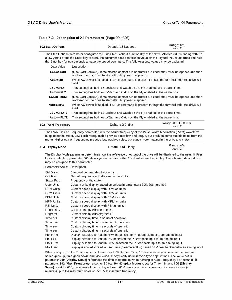
X4 AC Drive User’s Manual Chapter 7: X4 Parameters
802 Start Options Default: LS Lockout Range: n/aLevel 2
The Start Options parameter configures the Line Start Lockout functionality of the drive. All data values ending with “2” allow you to press the Enter key to store the customer speed reference value on the keypad. You must press and hold the Enter key for two seconds to save the speed command. The following data values may be assigned:
Data Value Description
LS Lockout (Line Start Lockout). If maintained contact run operators are used, they must be opened and then re-closed for the drive to start after AC power is applied.
AutoStart When AC power is applied, if a Run command is present through the terminal strip, the drive will start.
LSL w/FLY This setting has both LS Lockout and Catch on the Fly enabled at the same time.
Auto w/FLY This setting has both Auto-Start and Catch on the Fly enabled at the same time.
LS Lockout2 (Line Start Lockout). If maintained contact run operators are used, they must be opened and then re-closed for the drive to start after AC power is applied.
AutoStart2 When AC power is applied, if a Run command is present through the terminal strip, the drive will start.
LSL w/FLY 2 This setting has both LS Lockout and Catch on the Fly enabled at the same time.
Auto w/FLY2 This setting has both Auto-Start and Catch on the Fly enabled at the same time.
803 PWM Frequency Default: 3.0 kHz Range: 0.6-16.0 kHzLevel 2
The PWM Carrier Frequency parameter sets the carrier frequency of the Pulse-Width Modulation (PWM) waveform supplied to the motor. Low carrier frequencies provide better low-end torque, but produce some audible noise from the motor. Higher carrier frequencies produce less audible noise, but cause more heating in the drive and motor.
804 Display Mode Default: Std Disply Range: n/aLevel 2
The Display Mode parameter determines how the reference or output of the drive will be displayed to the user. If User Units is selected, parameter 805 allows you to customize the 3 unit values on the display. The following data values may be assigned to this parameter:
Parameter Value Description
Std Disply Standard commanded frequencyOut Freq Output frequency actually sent to the motorStator Freq Frequency of the statorUser Units Custom units display based on values in parameters 805, 806, and 807 RPM Units Custom speed display with RPM as unitsGPM Units Custom speed display with GPM as unitsFPM Units Custom speed display with FPM as unitsMPM Units Custom speed display with MPM as unitsPSI Units Custom speed display with PSI as unitsDegrees C Custom display with degrees CDegrees F Custom display with degrees FTime hrs Custom display time in hours of operationTime min Custom display time in minutes of operationTime sec Custom display time in seconds of operationTime sec Custom display time in seconds of operationFbk RPM Display is scaled to read in RPM based on the PI feedback input to an analog inputFbk PSI Display is scaled to read in PSI based on the PI feedback input to an analog inputFbk GPM Display is scaled to read in GPM based on the PI feedback input to an analog inputFbk User Display is scaled to read in User units (parameter 805) based on PI feedback input to an analog input
When using any of the Time functions, these refer to “Retention Time.” Retention time is an inverse function: as speed goes up, time goes down, and vice versa. It is typically used in oven-type applications. The value set in parameter 809 (Display Scale) references the time of operation when running at Max. Frequency. For instance, if parameter 302 (Max. Frequency) is set for 60 Hz, 804 (Display Mode) is set for Time min, and 809 (Display Scale) is set for 600, the scales of the display will read 60.0 min at maximum speed and increase in time (in minutes) up to the maximum scale of 6553.5 at minimum frequency.
Table 7-2: Description of X4 Parameters (Page 20 of 26)
1428D-0607 - 69 - © 2007 TB Wood’s All Rights Reserved
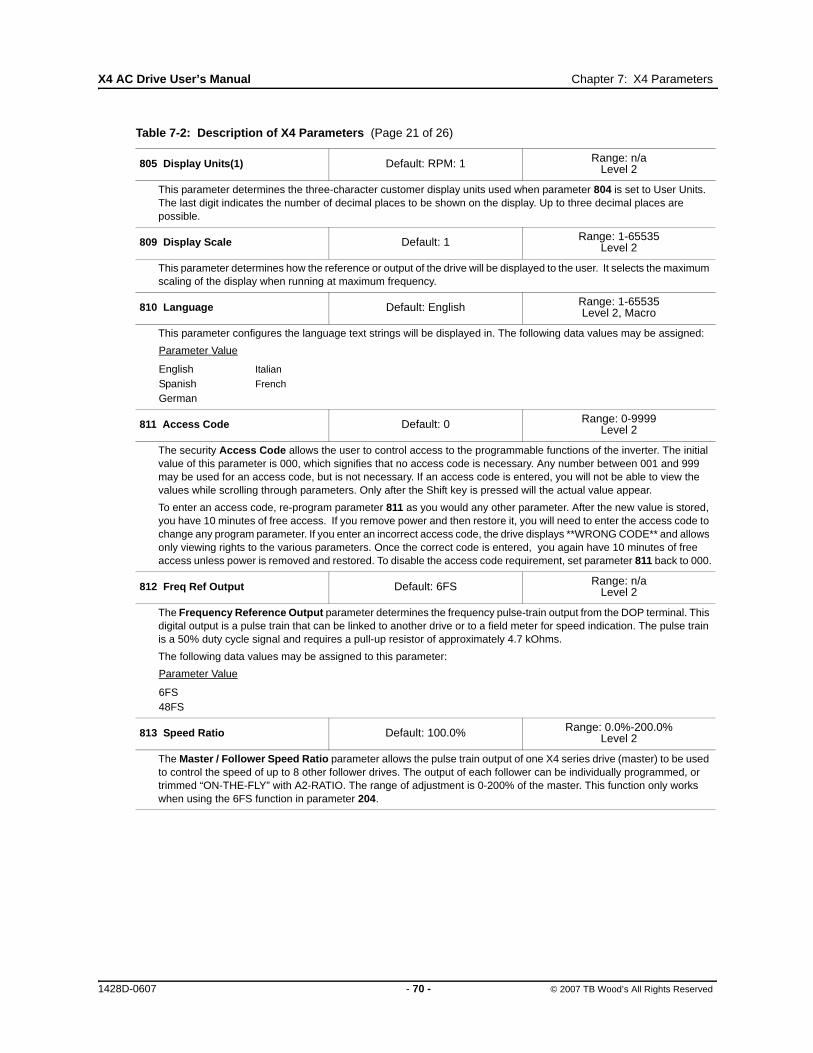
X4 AC Drive User’s Manual Chapter 7: X4 Parameters
805 Display Units(1) Default: RPM: 1 Range: n/aLevel 2
This parameter determines the three-character customer display units used when parameter 804 is set to User Units. The last digit indicates the number of decimal places to be shown on the display. Up to three decimal places are possible.
809 Display Scale Default: 1 Range: 1-65535Level 2
This parameter determines how the reference or output of the drive will be displayed to the user. It selects the maximum scaling of the display when running at maximum frequency.
810 Language Default: English Range: 1-65535Level 2, Macro
This parameter configures the language text strings will be displayed in. The following data values may be assigned:
Parameter Value
English Italian
Spanish French
German
811 Access Code Default: 0 Range: 0-9999Level 2
The security Access Code allows the user to control access to the programmable functions of the inverter. The initial value of this parameter is 000, which signifies that no access code is necessary. Any number between 001 and 999 may be used for an access code, but is not necessary. If an access code is entered, you will not be able to view the values while scrolling through parameters. Only after the Shift key is pressed will the actual value appear.
To enter an access code, re-program parameter 811 as you would any other parameter. After the new value is stored, you have 10 minutes of free access. If you remove power and then restore it, you will need to enter the access code to change any program parameter. If you enter an incorrect access code, the drive displays **WRONG CODE** and allows only viewing rights to the various parameters. Once the correct code is entered, you again have 10 minutes of free access unless power is removed and restored. To disable the access code requirement, set parameter 811 back to 000.
812 Freq Ref Output Default: 6FS Range: n/aLevel 2
The Frequency Reference Output parameter determines the frequency pulse-train output from the DOP terminal. This digital output is a pulse train that can be linked to another drive or to a field meter for speed indication. The pulse train is a 50% duty cycle signal and requires a pull-up resistor of approximately 4.7 kOhms.
The following data values may be assigned to this parameter:
Parameter Value
6FS48FS
813 Speed Ratio Default: 100.0% Range: 0.0%-200.0%Level 2
The Master / Follower Speed Ratio parameter allows the pulse train output of one X4 series drive (master) to be used to control the speed of up to 8 other follower drives. The output of each follower can be individually programmed, or trimmed “ON-THE-FLY” with A2-RATIO. The range of adjustment is 0-200% of the master. This function only works when using the 6FS function in parameter 204.
Table 7-2: Description of X4 Parameters (Page 21 of 26)
1428D-0607 - 70 - © 2007 TB Wood’s All Rights Reserved

X4 AC Drive User’s Manual Chapter 7: X4 Parameters
814 Display Status Default: Drive Load Range: 0.0%-200.0%Level 2
This parameter allows configuration of the additional parameter status field on the operate screen. The following fields can be configured:
Parameter Value Description Range Limit
Voltage Out Voltage being supplied to the motor Rated motor voltageCurrent Out Current being supplied to the motor 200% of drive ratingDrive Load Calculated percentage of drive rating 200% of drive ratingDrive Temp Calculation of total drive temp rating 100% of unit temp ratingPower Out Calculated power output of drive 250% of drive rating% of FLA Calculated percentage of drive rating Percent of motor FLA
816 Fly Catch Mode Default: Sweep Fwd Range: n/aLevel 2
This parameter configures how the “catch on the fly” operates.
Parameter Value Description
Sweep Fwd Catch on the fly algorithm sweeps through frequencies only in the forward direction while searching for the operating frequency
Sweep Rev Catch on the fly algorithm sweeps through frequencies only in the reverse direction while searching for the operating frequency
Sweep F/R Catch on the fly algorithm sweeps through frequencies in both directions while searching for the operating frequency. The direction that is chosen first depends on the direction of the command given to the drive. Note that this option is slower than the other two modes of operation.
850 PI Configure Default: No PI Range: n/aLevel 2
The PI Configure parameter determines what type of PI control is active in the drive.
PI can be active at all times, or activated using a digital input. If you select a digital input or function key as the means to enable PI control, remember to configure the parameter that sets the function of the digital input or function key to enable PI control to complete the implementation.
The following data values may be assigned to this parameter:
Parameter Value Description
No PI PI control is always inactive.Dir F-FWD Direct action with feed-forward.Rev F-FWD Reverse action with feed-forward.Dir F-FWD E Direct action with feed-forward, with PI enabled by DI.Rev F-FWD E Reverse action with feed-forward, with PI enabled by DI.Dir Full Direct action with full range.Rev Full Reverse action with full range.Dir Full E Direct action with full range, with PI enabled by DI.Rev Full E Reverse action with full range, with PI enabled by DI.
851 PI Feedback Default: Vin1 Range: n/aLevel 2
The PI Feedback parameter configures the feedback signal to be used in PI control.
The following data values may be assigned to this parameter:
Parameter Value Description
Vin1 Vin1 is the PI feedback.Cin Cin is the PI feedback.Vin2 Vin2 is the PI feedback.
Table 7-2: Description of X4 Parameters (Page 22 of 26)
1428D-0607 - 71 - © 2007 TB Wood’s All Rights Reserved

X4 AC Drive User’s Manual Chapter 7: X4 Parameters
852 PI Prop Gain Default: 0 Range: 0-2000Level 2
The PI Proportional Gain parameter configures the proportional gain that is applied to the PI control.
Note: Value must be greater than 0 for this to be active.
853 PI Int Gain Default: 0 Range: 0-10000Level 2
The PI Integral Gain parameter configures the integral gain that is applied to the PI control.
Note: Value must be greater than 0 for this to be active.
854 PI Feed Gain Default: 1000 Range: 0-2000Level 2
The PI Feed Gain parameter allows the feedback signal to be scaled. A setting of 1000 indicates 100.0%.
855 PI Error 1856 PI Error 2
Default: Read-Only Range: 0.00-100.00%Level 2
Both the PI Error 1 and PI Error 2 parameters are read-only; they provide feedback on how the PI control is operating.
857 PI High Corr Default: 100.00% Range: 0.00-100.00%Level 2
This parameter sets the high limit of the PI output.
858 PI Low Corr Default: 0.00% Range: 0.00-100.00%Level 2
This parameter sets the low limit of the PI output.
900 SIO Protocol Default: RTU N81 Range: n/aLevel 2 (SIO)
This parameter defines the protocol and the parity of the SIO port.
The following data values may be assigned to this parameter:
Parameter Value Description
RTU N81 No parity, 8 data bits, 1 stop bitRTU N82 No parity, 8 data bits, 2 stop bitsRTU E81 Even parity, 8 data bits, 1 stop bitRTU O81 Odd parity, 8 data bits, 1 stop bit
901 SIO Baud Rate Default: 9600 Range: n/aLevel 2 (SIO)
This parameter defines the baud rate of the SIO port.
The following data values may be assigned to this parameter:
Parameter Value
48009600192003840057600
902 Comm Drop # Default: 1 Range: 1-247Level 2 (SIO)
This parameter defines the network drop number for both SIO and IRDA communications.
903 SIO Timer Default: 1.0 sec Range: 0.0-60.0 secLevel 2 (SIO)
This parameter defines a watchdog timer that will require a valid communication in the specified time period while in SIO control. If the requirement is not met, a fault occurs.
Table 7-2: Description of X4 Parameters (Page 23 of 26)
1428D-0607 - 72 - © 2007 TB Wood’s All Rights Reserved

X4 AC Drive User’s Manual Chapter 7: X4 Parameters
904 SIO Cntl Word Default: 0x0000 Range: n/aLevel 2 (SIO)
The SIO Control Word parameter allows control of the drive through Modbus communications.
The following bits are used with this parameter:
905 Ext Ref Freq 1906 Ext Ref Freq 2
Default: 0.0 Hz Range: Min. Freq.-Max. Freq.Level 2 (SIO)
These parameters provide access for changing the frequency reference over the serial link.
908 Status Word Default: Read-Only Range: n/aLevel 2 (SIO)
The Status Word parameter provides status of the drive operation to a serial link user.
The following bits are used with this parameter:
909 DI Status Default: Read-Only Range: n/aLevel 2 (SIO)
This parameter provides a 10-bit status display.
The following bits are used with this parameter:
Table 7-2: Description of X4 Parameters (Page 24 of 26)
Bit When Set to 1 Signifies Bit When Set to 1 Signifies
8 Alt Ramp 0 SLC (Run)9 PI Enable 1 SLF (Ref)10 Not Used 2 FWD11 Cur Lim 3 REV12 DCI 4 FEXT213 CTS 5 Preset Input 1 (PS1)14 Ref Switch 6 Preset Input 2 (PS2))15 Fault Reset 7 Preset Input 3 (PS3)
15 14 13 12 11 10 9 8 7 6 5 4 3 2 1 0
Bit When Set to 1 Signifies Bit When Set to 1 Signifies
8 Alt Ramp 0 SLC (Run)9 SL Override 1 SLF (Ref)10 Remote 2 FWD run11 Curr Lim 3 REV run12 DCI 4 FEXT213 Jogging 5 Accel14 Zero Spd 6 Decel15 Drive Flt 7 At Speed
15 14 13 12 11 10 9 8 7 6 5 4 3 2 1 0
Bit When Set to 1 Signifies Bit When Set to 1 Signifies
5 DI3 Input 0 FWD Input6 DI4 Input 1 REV Input7 DI5 Input 2 R/J Input8 MOL Input 3 DI1 Input9 EN Input 4 DI2 Input
9 8 7 6 5 4 3 2 1 0
1428D-0607 - 73 - © 2007 TB Wood’s All Rights Reserved

X4 AC Drive User’s Manual Chapter 7: X4 Parameters
910 Vin1 Status911 Cin Status912 Vin2 Status
Default: Read-Only Range: 0.00-100.00%Level 2 (SIO)
Parameter 910 provides the input percentage applied to the Vin1 terminal; parameter 911 provides the input percentage applied to the Cin terminal; and parameter 912 provides the input percentage applied to the Vin2 terminal.
913 Output Status Default: Read-Only Range: n/aLevel 2 (SIO)
This parameter provides a 10-bit binary status display. A “1” in the status word indicates that the output is active.
The following bits are used with this parameter:
914 Vmet Status915 Imet Status
Default: Read-Only Range: 0.00-100.00%Level 2 (SIO)
Parameter 914 provides the output percentage applied to the Vmet terminal; parameter 915 provides the output percentage applied to the Imet terminal.
916 Infrared Baud Default: 9600 Range: n/aLevel 2 (SIO)
This parameter defines the baud rate of the IRDA port.
The following data values may be assigned to this parameter:
Parameter Value
9600192003840057600
931 Seq Cntl 1 932 Seq Cntl 2933 Seq Cntl 3934 Seq Cntl 4935 Seq Cntl 5936 Seq Cntl 6937 Seq Cntl 7938 Seq Cntl 8939 Seq Cntl 9
Default: 00000000000 Range: n/aLevel 2 (SEQ)
These parameters each provide a 10-bit binary status display. See “Using the X4 Program Sequencer” on page 75.
The following bits are used with each of these parameters:
Bit 0-2=Speed SelBit 3=Accl SelBit 4-6=Event LengthBit 7-8=Dir SelBit 9-10=Output Sel
Table 7-2: Description of X4 Parameters (Page 25 of 26)
Bit When Set to 1 Signifies Bit When Set to 1 Signifies
5 N/A 0 R1 Output6 N/A 1 R2 Output7 N/A 2 DO1 Output8 N/A 3 DO2 Output9 N/A 4 N/A
9 8 7 6 5 4 3 2 1 0
1428D-0607 - 74 - © 2007 TB Wood’s All Rights Reserved

X4 AC Drive User’s Manual Chapter 7: X4 Parameters
7.4 Using the X4 Program Sequencer
The X4 AC drive offers functionality that allows users to program up to nine independent operation states of the drive. This functionality is called the “program sequencer” because it allows the drive to sequence through the operation states programmed by the user. The X4 Program Sequencer can be used in applications that would normally require external intelligence, such as a simple programmable logic controller.
7.4.1 Enabling the X4 Program SequencerThe X4 Program Sequencer can be enabled with parameter 491 (Seq Appl), found in the Application Macro programming mode of the X4 keypad. This parameter configures:
• Whether the sequencer is enabled,
• The time base used for all timing of the sequencer,
• Whether other sequencer parameters are visible in Level 2 programming.
Table 7-3 shows the options for this parameter:
7.4.2 Controlling the X4 Program SequencerThe Program Sequencer can be activated and controlled from either the keypad or the terminal strip. It is not possible to control the sequencer through the serial link. The control method of the program sequencer is determined by parameter 201, Input Mode. Setting the Input Mode parameter also
951 Seq Count 1952 Seq Count 2 953 Seq Count 3954 Seq Count 4 955 Seq Count 5956 Seq Count 6957 Seq Count 7958 Seq Count 8959 Seq Count 9
Default: 0 Range: 0-65535Level 2 (SEQ)
These parameters configure the time, number of pulses, or analog level of sequencer steps 1 through 9, respectively. See “Using the X4 Program Sequencer” on page 75.
Table 7-3: Seq Appl Parameter Options
Options Value Meaning
Disabled 0The Sequencer mode of the X4 is not active and the sequencer parameters are not visible in Level 2 programming.
1 sec base 1The Sequencer mode of the X4 is active, sequencer parameters are visible in Level 2, and all timing for the sequencer will be on a 1-second base.
.1 sec base 2The Sequencer mode of the X4 is active, sequencer parameters are visible in Level 2, and all timing for the sequencer will be on a .1-second base.
.01 sec base 3The Sequencer mode of the X4 is active, sequencer parameters are visible in Level 2, and all timing for the sequencer will be on a .01-second base.
Table 7-2: Description of X4 Parameters (Page 26 of 26)
1428D-0607 - 75 - © 2007 TB Wood’s All Rights Reserved
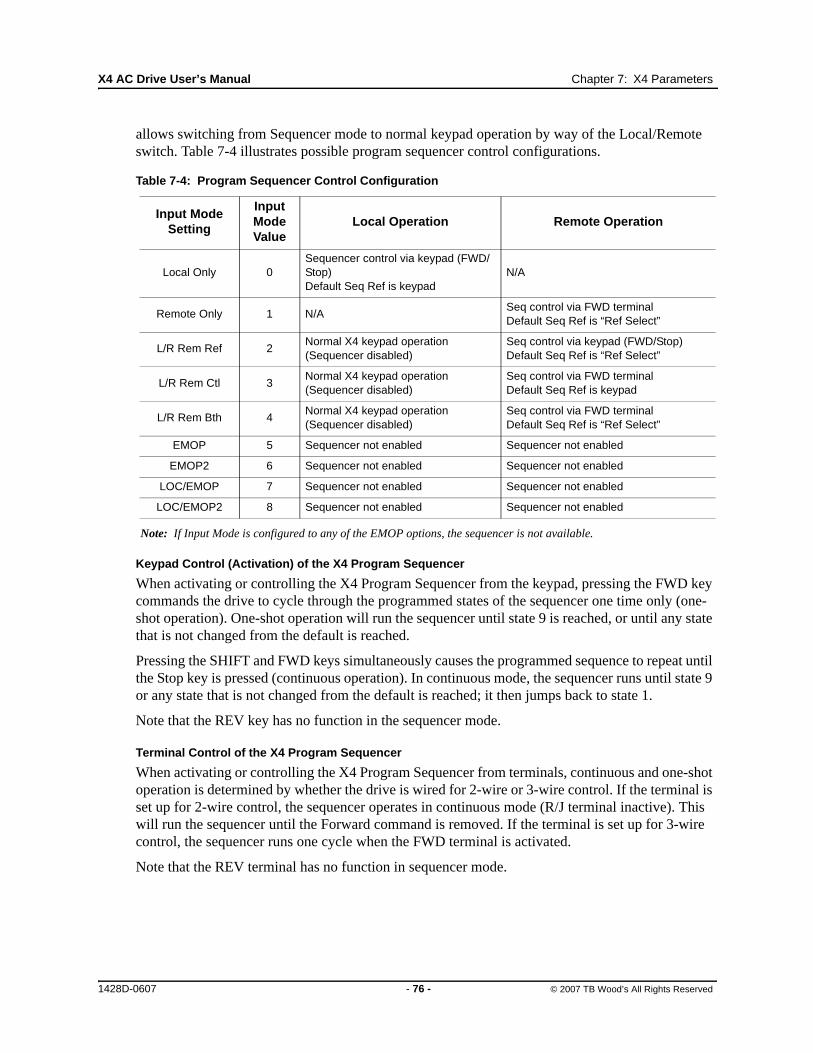
X4 AC Drive User’s Manual Chapter 7: X4 Parameters
allows switching from Sequencer mode to normal keypad operation by way of the Local/Remote switch. Table 7-4 illustrates possible program sequencer control configurations.
Note: If Input Mode is configured to any of the EMOP options, the sequencer is not available.
Keypad Control (Activation) of the X4 Program Sequencer
When activating or controlling the X4 Program Sequencer from the keypad, pressing the FWD key commands the drive to cycle through the programmed states of the sequencer one time only (one-shot operation). One-shot operation will run the sequencer until state 9 is reached, or until any state that is not changed from the default is reached.
Pressing the SHIFT and FWD keys simultaneously causes the programmed sequence to repeat until the Stop key is pressed (continuous operation). In continuous mode, the sequencer runs until state 9 or any state that is not changed from the default is reached; it then jumps back to state 1.
Note that the REV key has no function in the sequencer mode.
Terminal Control of the X4 Program Sequencer
When activating or controlling the X4 Program Sequencer from terminals, continuous and one-shot operation is determined by whether the drive is wired for 2-wire or 3-wire control. If the terminal is set up for 2-wire control, the sequencer operates in continuous mode (R/J terminal inactive). This will run the sequencer until the Forward command is removed. If the terminal is set up for 3-wire control, the sequencer runs one cycle when the FWD terminal is activated.
Note that the REV terminal has no function in sequencer mode.
Table 7-4: Program Sequencer Control Configuration
Input Mode Setting
Input Mode Value
Local Operation Remote Operation
Local Only 0Sequencer control via keypad (FWD/Stop)Default Seq Ref is keypad
N/A
Remote Only 1 N/ASeq control via FWD terminalDefault Seq Ref is “Ref Select”
L/R Rem Ref 2Normal X4 keypad operation (Sequencer disabled)
Seq control via keypad (FWD/Stop)Default Seq Ref is “Ref Select”
L/R Rem Ctl 3Normal X4 keypad operation (Sequencer disabled)
Seq control via FWD terminalDefault Seq Ref is keypad
L/R Rem Bth 4Normal X4 keypad operation (Sequencer disabled)
Seq control via FWD terminalDefault Seq Ref is “Ref Select”
EMOP 5 Sequencer not enabled Sequencer not enabled
EMOP2 6 Sequencer not enabled Sequencer not enabled
LOC/EMOP 7 Sequencer not enabled Sequencer not enabled
LOC/EMOP2 8 Sequencer not enabled Sequencer not enabled
1428D-0607 - 76 - © 2007 TB Wood’s All Rights Reserved
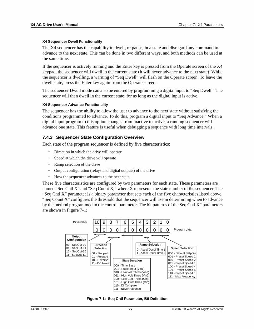
X4 AC Drive User’s Manual Chapter 7: X4 Parameters
X4 Sequencer Dwell Functionality
The X4 sequencer has the capability to dwell, or pause, in a state and disregard any command to advance to the next state. This can be done in two different ways, and both methods can be used at the same time.
If the sequencer is actively running and the Enter key is pressed from the Operate screen of the X4 keypad, the sequencer will dwell in the current state (it will never advance to the next state). While the sequencer is dwelling, a warning of “Seq Dwell” will flash on the Operate screen. To leave the dwell state, press the Enter key again from the Operate screen.
The sequencer Dwell mode can also be entered by programming a digital input to “Seq Dwell.” The sequencer will then dwell in the current state, for as long as the digital input is active.
X4 Sequencer Advance Functionality
The sequencer has the ability to allow the user to advance to the next state without satisfying the conditions programmed to advance. To do this, program a digital input to “Seq Advance.” When a digital input program to this option changes from inactive to active, a running sequencer will advance one state. This feature is useful when debugging a sequence with long time intervals.
7.4.3 Sequencer State Configuration OverviewEach state of the program sequencer is defined by five characteristics:
• Direction in which the drive will operate
• Speed at which the drive will operate
• Ramp selection of the drive
• Output configuration (relays and digital outputs) of the drive
• How the sequencer advances to the next state.
These five characteristics are configured by two parameters for each state. These parameters are named “Seq Cntl X” and “Seq Count X,” where X represents the state number of the sequencer. The “Seq Cntl X” parameter is a binary parameter that sets each of the five characteristics listed above. “Seq Count X” configures the threshold that the sequencer will use in determining when to advance by the method programmed in the control parameter. The bit patterns of the Seq Cntl X” parameters are shown in Figure 7-1:
Figure 7-1: Seq Cntl Parameter, Bit Definition
10 9 8 7 6 5 4 3 2 1 0
0 0 0 0 0 0 0 0 0 0 0
Bit number
Program data
Output Configuration
00 - SeqOut-0001 - SeqOut-0110 - SeqOut-1011 - SeqOut-11
Direction Selection
00 - Stopped01 - Forward10 - Reverse11 - DC Inject
State Duration
000 - Time Base001 - Pulse Input (Vin1)010 - Low Volt Thres (Vin2)011 - High Volt Thres (Vin2)100 - Low Curr Thres (Cin)101 - High Curr Thres (Cin)110 - DI Compare111 - Never Advance
Ramp Selection
0 - Accel/Decel Time 11 - Accel/Decel Time 2
Speed Selection
000 - Default Setpoint001 - Preset Speed 1010 - Preset Speed 2011 - Preset Speed 3100 - Preset Speed 4101 - Preset Speed 5110 - Preset Speed 6111 - Max Frequency
1428D-0607 - 77 - © 2007 TB Wood’s All Rights Reserved

X4 AC Drive User’s Manual Chapter 7: X4 Parameters
X4 Sequencer Speed Selection
Table 7-5 gives more information on the speed selection options available in the X4 sequencer by programming bits 0, 1, and 2 of each state’s control parameter. The options include any Preset Speed, Max Frequency, or allowing the reference to be determined in the normal X4 control path.
X4 Sequencer Ramping Selection
When the sequencer is active, the active ramp is no longer determined by parameter “Ramp Select.” The user, however, does have the choice of using the main ramps (Accel Time 1/Decel Time1), or the alternate ramps (Accel Time 2/Decel Time 2) for each independent state. This is determined by bit 3 of the control parameter. If bit 3 is set to 1, then the alternate ramps are used (Accel Time 2/Decel Time 2).
Sequencer Output Configuration
The X4 Program Sequencer allows digital outputs to be activated during states of the sequencer. This function could be used to activate other devices in a system or to signal to an operator when a part of the sequence is active. The user sets the digital output by setting bits 9 and 10 of the control parameter with a binary value, and then sets a digital output parameter with the option for that same binary value. For example, if a control state was output configured for a binary value of 11, then any digital output configured to “SeqOut-11” would be activated during that time.
Sequencer Direction Selection
The sequencer allows each state to be configured as running Forward, Reverse, Stopped, or DC Injected by setting bits 7 and 8 of the control parameters.
Sequencer State Duration
Bits 4, 5, and 6 of each sequencer control parameter specify how that step will allow advancement to the next step. The options for advancement are time, pulse input, voltage threshold, current threshold, or digital input comparison. After the advancement method is selected with these bits, the threshold of advancement is determined by the state’s count parameter (see the next paragraph).
Sequencer State Advance Threshold (via Count Parameter)
The sequencer count parameters work in conjunction with the state duration configuration in the control parameter to determine when to advance to the next state. The function of this parameter is dependent on the state duration configuration as defined in Table 7-6 on page 79. The range of data
Table 7-5: Speed Selection Options
Binary Value Definition (Resulting Speed)
000Speed selection as in normal X4 operation, as defined by parameters 204 (Ref Select) and 201 (Input Mode).
001 Value of parameter Preset Speed 1(303)
010 Value of parameter Preset Speed 2(304)
011 Value of parameter Preset Speed 3(305)
100 Value of parameter Preset Speed 4(306)
101 Value of parameter Preset Speed 5(307)
110 Value of parameter Preset Speed 6(308)
111 Value of parameter Max Frequency (302)
1428D-0607 - 78 - © 2007 TB Wood’s All Rights Reserved

X4 AC Drive User’s Manual Chapter 7: X4 Parameters
programmed into this parameter can be from 0 to 65,535, and can represent time, pulse counts, analog voltage thresholds, analog current thresholds, or digital comparison values.
Table 7-6: Seq Count Definition Based on Cntl Parameter Configuration
Bits 4,5,6 of
Seq CntlDescription of Seq Count Function
000
Time Base - The current sequencer state will last for a time interval equal to the number “Seq Count X” multiplied by the time base configured in the Seq Appl parameter.
Seq Appl Setting Time to Advance Maximum Sequence Time
1 sec Base (1 sec) * (Seq Count X) 18.2 hours
.1 sec Base (0.1 sec) * (Seq Count X) 1.82 hours
0.1 sec Base (0.01 sec) * (Seq Count X) 10.92 minutes
001Pulse Count - The current sequencer state will last until the number of pulses programmed into “Seq Count X” is detected on terminal Vin1.
010
Low Analog Voltage Threshold - The active sequencer state lasts until the voltage signal applied to terminal Vin2 is < a value programmed into “Seq Count X.” The value programmed into “Seq Count X” should be the percentage of input after span and offset are applied (where 100.00% = 10000).Note: The % of analog input after span and offset can be read in parameter 912, Vin2 Status.
011
High Analog Voltage Threshold - The active sequencer state lasts until the voltage signal applied to terminal Vin2 is > a value programmed into “Seq Count X.” The value programmed into “Seq Count X” should be the percentage of input after span and offset are applied (where 100.00% = 10000).Note: The % of analog input after span and offset can be read in parameter 912, Vin2 Status.
100
Low Analog Current Threshold - The active sequencer state lasts until the current signal applied to Cin terminals is < a value programmed into “Seq Count X.” The value programmed into “Seq Count X” should be the percentage of input after span and offset are applied (where 100.00% = 10000).Note: The % of analog input after span and offset can be read in parameter 911, Cin Status.
101
High Analog Current Threshold - The active sequencer state lasts until the current signal applied to Cin terminals is > a value programmed into “Seq Count X.” The value programmed into “Seq Count X” should be the percentage of input after span and offset are applied (where 100.00% = 10000).Note: The % of analog input after span and offset can be read in parameter 911, Cin Status.
110
Digital Comparison - The active sequencer state lasts until the binary value of digital inputs configured to Seq1, Seq2, and Seq3 is equal to the value programmed into "Seq Count X." Note: For this option to work, "DIx Configure" parameters must be set to "Seq1," "Seq2," and "Seq3.”
Seq CountDigital Input Terminals
DescriptionSeq1 Seq2 Seq3
0 0 0 0 No input active
1 1 0 0 Seq1 active
2 0 1 0 Seq2 active
3 1 1 0 Seq1 & Seq2 active
4 0 0 1 Seq3 active
5 1 0 1 Seq1 & Seq3 active
6 0 1 1 Seq2 & Seq3 active
7 1 1 1Seq1, Seq2, Seq3 active
111 The sequencer will never advance if this option is selected.
1428D-0607 - 79 - © 2007 TB Wood’s All Rights Reserved

X4 AC Drive User’s Manual Chapter 7: X4 Parameters
7.4.4 Sequencer Status IndicatorsWhen the sequencer is enabled, the control path indication field on the keypad will indicate SQx, where x represents the active state of the sequencer. A sample operate screen (where the sequencer is in state 1) is shown below:
When the sequencer is running, a warning, “Seq Running,” will flash on the screen to indicate that the drive control state may change without user input. For example:
When the sequencer is dwelling (pausing) in a state, a warning, “Seq Dwell,” will flash on the screen to indicate that the sequencer will not advance. For example:
7.4.5 Sample Sequencer ProgramA machine is required to run in the forward direction at 50 Hz for one hour, then quickly decelerate to a stop. While stopped, a digital output must be enabled to sound an alarm to an operator. After two minutes, the machine must accelerate in the reverse direction to 5 Hz until a limit switch is activated., causing the drive to decelerate to a stop. The following three sequential states can be programmed using only the drive:
First, since two of the sequential states are time-based, the proper setting of the “Seq Appl” parameter must be determined. Since there is not time required that has resolution needed of less than one second, the “1 sec Base” option is the easiest to use. If greater resolution is needed (for example, if a state needed to last for 2.5 seconds), another option should be chosen.
Since the sequence requires use of a digital input and a digital output, two non-sequencer parameters need to be used. Set the parameter “DI1 Configure” to “Seq1” and the parameter “DO1 Configure” to “SeqOut-01.”
Since control of the sequencer is only needed from the keypad, the configuration of the “Input Mode” parameter should be “Local Only.”
Table 7-7: Sample Sequencer Program Requirements
State 1 State 2 State 3
Direction Selection Forward Stop Reverse
Speed Selection 50 Hz Zero speed 5 Hz
Ramp Selection Primary Alternate Primary
Output Configuration SeqOut-00 SeqOut-01 SeqOut-10
State Duration 1 hour 2 minutes Until DI active
Q 1 : S t o p p eS d0 . 0 H z + 0 %
Q 1 : S t o p p eS d0 . 0 H z + 0 %
Q 1 : S e q R u n n i nS g0 . 0 H z + 0 %
Q 1 : S t o p p eS d0 . 0 H z + 0 %
Q 1 : S e q D w e lS l0 . 0 H z + 0 %
1428D-0607 - 80 - © 2007 TB Wood’s All Rights Reserved

X4 AC Drive User’s Manual Chapter 7: X4 Parameters
Required parameter modifications for this program are provided in Table 7-8, with explanations.
Table 7-8: Required Parameter Settings for Sample Sequencer Program
Parameter Value Explanation
Seq Appl “1 sec Base” Sets 1 second time increments
DI1 Configure “Seq1” Allows DI1 to end state 3
DO1 Configure “SeqOut-01” Allows DO1 to be active in state 2
Preset Speed 1 5 Hz Speed for state 3
Preset Speed 6 50 Hz Speed for state 1
Seq Cntl1 00010000110No outputs/FWD/Timed/Primary Ramp/Preset Speed 6
Seq Count 1 3600 1 hour = 3600 seconds
Seq Cntl 2 01000001000 Enable Output/Stop/Timed/Alt Ramp/Speed Ignored
Seq Count 2 120 2 minutes = 120 seconds
Seq Cntl 3 00101100001No outputs/REV/DI Value/Primary Ramp/Preset Speed 1
Seq Count 3 1 Seq1 active
1428D-0607 - 81 - © 2007 TB Wood’s All Rights Reserved
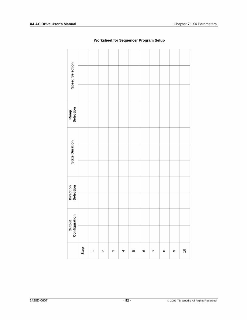
X4 AC Drive User’s Manual Chapter 7: X4 Parameters
Worksheet for Sequencer Program Setup
Ou
tpu
t C
on
fig
ura
tio
nD
irec
tio
n
Sel
ecti
on
Sta
te D
ura
tio
nR
amp
S
elec
tio
nS
pee
d S
elec
tio
n
Ste
p
1 2 3 4 5 6 7 8 9 10
1428D-0607 - 82 - © 2007 TB Wood’s All Rights Reserved

Chapter 8: Troubleshooting
8.1 X4 Fault Codes
Table 8-1 shows the fault codes that may be displayed during X4 AC drive operation, along with suggestions for recovering from the fault condition.
When faults occur, you can access the status parameters that are saved along with the fault (Advanced Fault history). To view these parameters, which store the drive’s status at the time of the fault, view Fault History, and select Last Fault. Press the Shift key while viewing the last fault, and then use the UP and DOWN arrow keys to scroll through the stored drive status parameters. Press the Shift key again to return to the programming mode fault parameter.
Table 8-1: X4 Fault Codes (Page 1 of 5)
Code Fault Display DescriptionAdv. Fault
Code Explanation Suggestions for Recovery
1 System System fault
0,1,2 Internal microprocessor problemConsult factory for repair or replacement.
3 Thermistor profile incorrectConsult factory for repair or replacement.
2 EE Checksum Checksum error
0Memory problem when reflashing the drive’s memory
• Reset drive to factory settings.• Consult factory.
1,2,3 Conflict in drive’s memory• Reset drive to factory settings.• Consult factory.
4
Unable to write an EE parameter after a parameter has been changed through the keypad or SIO
• Reset drive to factory settings.• Consult factory.
5
The drive is receiving EE write requests faster than they can be processed. This would typically be caused by writing parameters too frequently through Modbus.
Slow down the frequency of Modbus writes.
3 Curr CalibrCurrent calibration
fault
0Current calibration fault on phase T1/U
• Check the motor connections to the terminal strip of the drive and at the motor.
• Have motor checked.• Consult factory for repair or
replacement of drive.
1Current calibration fault on phase T2/V
2Current calibration fault on phase T3/W
4 Power Supp Power supply fault 05V supply is below 4 Vdc for more than 100 ms
• Increase resistance between REF and analog inputs.
• Check wiring to REF terminals.• Consult factory.
6 IOC TripInstantaneous overcurrent trip
0Short circuit was detected on power-up
• Remove the short from the power wiring
• Check for shorted motor• Consult factory.1
Short circuit was detected during operation
7 MOL MOL contact fault 0The MOL digital input was activated, depending on pull-up or pull-down logic configuration
Reset MOL contact or remove condition causing the MOL contact activation.
Note: Shaded faults are auto-resettable, except where noted.
1428D-0607 - 83 - © 2007 TB Wood’s All Rights Reserved
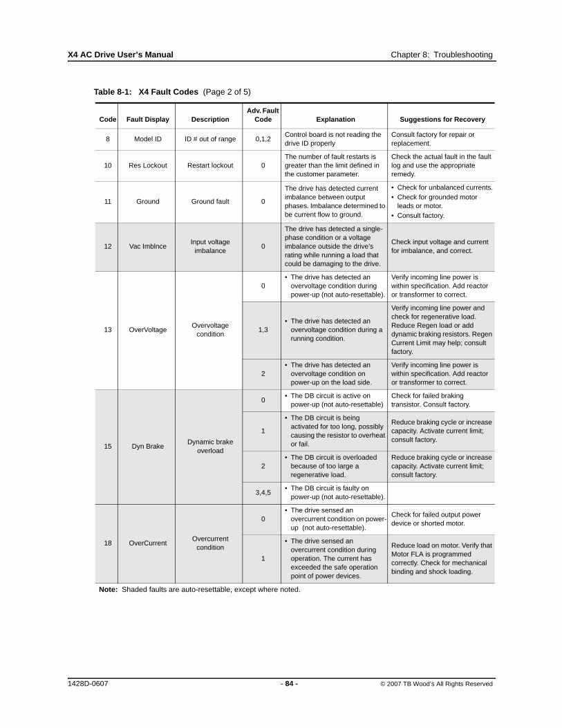
X4 AC Drive User’s Manual Chapter 8: Troubleshooting
8 Model ID ID # out of range 0,1,2Control board is not reading the drive ID properly
Consult factory for repair or replacement.
10 Res Lockout Restart lockout 0The number of fault restarts is greater than the limit defined in the customer parameter.
Check the actual fault in the fault log and use the appropriate remedy.
11 Ground Ground fault 0
The drive has detected current imbalance between output phases. Imbalance determined to be current flow to ground.
• Check for unbalanced currents.• Check for grounded motor
leads or motor.• Consult factory.
12 Vac ImblnceInput voltage
imbalance0
The drive has detected a single-phase condition or a voltage imbalance outside the drive’s rating while running a load that could be damaging to the drive.
Check input voltage and current for imbalance, and correct.
13 OverVoltageOvervoltage
condition
0• The drive has detected an
overvoltage condition during power-up (not auto-resettable).
Verify incoming line power is within specification. Add reactor or transformer to correct.
1,3• The drive has detected an
overvoltage condition during a running condition.
Verify incoming line power and check for regenerative load. Reduce Regen load or add dynamic braking resistors. Regen Current Limit may help; consult factory.
2• The drive has detected an
overvoltage condition on power-up on the load side.
Verify incoming line power is within specification. Add reactor or transformer to correct.
15 Dyn BrakeDynamic brake
overload
0• The DB circuit is active on
power-up (not auto-resettable)Check for failed braking transistor. Consult factory.
1
• The DB circuit is being activated for too long, possibly causing the resistor to overheat or fail.
Reduce braking cycle or increase capacity. Activate current limit; consult factory.
2• The DB circuit is overloaded
because of too large a regenerative load.
Reduce braking cycle or increase capacity. Activate current limit; consult factory.
3,4,5• The DB circuit is faulty on
power-up (not auto-resettable).
18 OverCurrentOvercurrent
condition
0• The drive sensed an
overcurrent condition on power-up (not auto-resettable).
Check for failed output power device or shorted motor.
1
• The drive sensed an overcurrent condition during operation. The current has exceeded the safe operation point of power devices.
Reduce load on motor. Verify that Motor FLA is programmed correctly. Check for mechanical binding and shock loading.
Table 8-1: X4 Fault Codes (Page 2 of 5)
Code Fault Display DescriptionAdv. Fault
Code Explanation Suggestions for Recovery
Note: Shaded faults are auto-resettable, except where noted.
1428D-0607 - 84 - © 2007 TB Wood’s All Rights Reserved

X4 AC Drive User’s Manual Chapter 8: Troubleshooting
19 Over TempOver- temperature
condition
0• The temperature of the heatsink
exceeded a temperature limit.
Check that ambient temperature does not exceed drive’s rating. Check for fan operation (assuming drive has fans installed).
1• The temperature of the control
board exceeded a temperature limit.
Check that ambient temperature does not exceed drive’s rating. Check for fan operation (assuming drive has fans installed).
2• The drive sensed the heatsink
thermistor sensor is faulty or not connected properly.
Check thermistor connections or replace. Consult factory.
3
• The drive sensed the control board thermistor sensor is faulty or not connected properly.
Check thermistor connections or replace. Consult factory.
20 Motor TOLMotor timed overload trip
0The drive detected an overload that exceeds the customer’s defined overload setting.
Check load current demand. Verify Motor FLA is programmed to the correct value. Verify TOL characteristic is correct for the application.
21 Low Temp Low temperature 0This fault occurs if the temperature of the heatsink falls below -10.0 degrees C.
Verify that ambient temperature is within the drive’s specifications; increase the ambient temperature if necessary.
22 Ref LossSpeed reference
loss0
The drive detected the analog input was configured to fault if the input current went below the level specified by customer parameters.
Check physical connections for reference signal. Check that programming for 4-20 mA signal is correct. Verify that signal to the drive is correct.
23 Brk WireBroken wire
detection0
The drive detected that the potentiometer circuit wiring opened and generated a fault.
Check wiring for loss of connection to control terminals. Check that a proper-value potentiometer is installed.
24 Keypad Loss Keypad loss
0
This fault occurs because of a problem with the keypad or a keypad connection. It occurs if the drive detects that it cannot read any key presses.
Check the connection from keypad to control board. Note that the keypad is not designed for remote mounting.
1
This fault occurs because of a problem with the keypad, a keypad connection, or the wrong keypad is being used. It occurs if the keypad ID for an X4 cannot be read.
2
This fault occurs because of a problem with the keypad or a keypad connection. It occurs if the drive detects that it cannot write to the LCD.
Table 8-1: X4 Fault Codes (Page 3 of 5)
Code Fault Display DescriptionAdv. Fault
Code Explanation Suggestions for Recovery
Note: Shaded faults are auto-resettable, except where noted.
1428D-0607 - 85 - © 2007 TB Wood’s All Rights Reserved

X4 AC Drive User’s Manual Chapter 8: Troubleshooting
25 Comm Loss Communication loss 0
This fault occurs when the drive is in a serial link control path and the amount of time since the last Modbus comm. exceeds the time set in parameter 903 (SIO Timer).
Check connections to the Modbus port. Adjust value of parameter 903 (SIO Timer) as needed.
26 Regen Time Regen timeout 0
This fault occurs if the drive takes more time to decelerate to a stop than is allowed. The timeout is determined by the longest deceleration ramp time (Decel1 or Decel2) plus the Regen Timeout parameter.
Reduce the amount of regenerative energy or iincrease the Regen timeout parameter.
27 Pwr Bridge Power bridge fault 0,1,2The drive detected a failure in the output power devices.
Check for failed input power device.
28 Drive TOL Drive timed overload 0The drive sensed an overload that exceeded the drive rating.
Check that load conditions do not exceed the drive’s rating (120% for 60 seconds from nameplate current rating for normal duty and 150% or rated current for 60 seconds heavy duty).
29 Stuck Key Stuck key error 0
This fault occurs if a key press is detected upon power-up. This would occur because of a defective keypad or because someone was holding down a key when powering-up the drive.
Check for stuck keypad and repair or replace. Consult factory.
30 Param RangeParameter out of
range0
One of the customer parameters is out of range.
Check for a parameter value saved out of the standard range. Reset parameters to factory default. Consult factory.
31 Pwr Wiring Power wiring error
0This fault flags a problem with the drive wiring. Check that input power wiring is
not connected to load power terminals. Consult factory.1
This fault can occur if an IOC fault is detected during the power wiring test.
32 Low Voltage Low voltage trip 0
This fault occurs if a power dip occurs when the drive is operating, and the drive is not able to ride through the power dip before shutting off outputs.
Verify that input line power is within the drive’s specifications. Add a transformer or reduce demands to power feed. Consult factory.
33 1Ph Overload 1Ph overload 0
If the user configures parameter 517 (Single Phase) for single-phase operation, this fault occurs if the bus voltage ripple is outside the limit of the drive.
Check that input power demand does not exceed the drive’s capacity for single-phase operation. Consult factory.
34 RS Meas. FailStator resistance
measurement failed0
If the drive cannot measure the stator resistance properly, this fault occurs.
Try the routine again and if the fault occurs twice, consult the factory.
Table 8-1: X4 Fault Codes (Page 4 of 5)
Code Fault Display DescriptionAdv. Fault
Code Explanation Suggestions for Recovery
Note: Shaded faults are auto-resettable, except where noted.
1428D-0607 - 86 - © 2007 TB Wood’s All Rights Reserved

X4 AC Drive User’s Manual Chapter 8: Troubleshooting
35 Fan LossLoss of fan control or
operation
0There is a problem with the heat sink fan.
Consult factory.
1
There is a problem with the internal fan. This occurs only on Size 4 and 5 models. All other models display a fan error warning.
Note that this is lack of fan control, so the fan can be spinning and this fault will still occur. This can happen if the fan is on and should not be, or if the fan feedback signals are obstructed from getting to the control board.
Table 8-1: X4 Fault Codes (Page 5 of 5)
Code Fault Display DescriptionAdv. Fault
Code Explanation Suggestions for Recovery
Note: Shaded faults are auto-resettable, except where noted.
1428D-0607 - 87 - © 2007 TB Wood’s All Rights Reserved
EU Declaration of Conformity
WE: TB Wood’s, Inc. 440 North Fifth Avenue Chambersburg, PA 17201 USA
hereby declare that the products:
Product Name: X4 Series
Model Number: X4C1S010C, X4C20010C, X4C20020C, X4C20030C, X4C20050C, X4C20075C, X4C20100C, X4C20150C, X4C20200C, X4C20300C, X4C40010C, X4C40020C, X4C40030C, X4C40050C, X4C40075C, X4C40100C, X4C40150C, X4C40200C, X4C40250C, X4C40300C, X4C40400C, X4C40500C, X4C40600C, X4C40750C, X4C41000C, X4C41250C, X4C41500C, X4C42000C, X4C50010C, X4C50020C, X4C50030C, X4C50050C, X4C50075C, X4C50100C, X4C50150C, X4C50200C, X4C50250C, X4C50300C, X4C50400C, X4C50500C, X4C50600C, X4C50750C, X4C51000C, X4C51250C, X4C51500C, X4C52000C
have been designed and manufactured in accordance with standards:
Low Voltage Directive: EN50178 Electronic equipment for use in power installations
Electromagnetic compatibility: EN61800-3 Adjustable speed electrical power drive systems – Part 3: EMC product standard including specific test methods
The products referenced above are for the use of control of the speed of AC motors.
The use in residential and commercial premises (Class B) requires an optional WLF series filter.
Via internal mechanisms and Quality Control, it is verified that these products conform to the requirements of the Directive and applicable standards.
Chambersburg, PA, USA — May 31, 2007
Frank H. CustisMarketing Manager,Electronics Division


USA SALES
TB Wood’s Incorporated Headquarters440 North Fifth AvenueChambersburg, Pennsylvania 17201-1778Telephone: 888-TBWOODS or 717-264-7161FAX: 717-264-6420Website: www.tbwoods.com
INTERNATIONAL SALES
CanadaT.B. Wood’s Canada Ltd.750 Douro StreetStratford, Ontario, Canada N5A 6V6Telephone: 519-271-5380FAX: 519-271-3094
GermanyBerges electronic GmbHIndustriestraße 13D-51709 Marienheide, GermanyTelephone: 49-2264-17-0FAX: 49-2264-17-126
IndiaTB Wood’s (India) Private Limited#27, ‘E’ II Cross, Electronic CityHosur RoadBangalore, 560 100 IndiaTelephone: 080-30280123FAX: 080-30280124
ItalyBerges electronic s.r.l.Via Zona Industriale, 11I-39025 Naturno, ItalyTelephone: 39-0473-67-1911FAX: 39-0473-67-1909
MexicoIndustrial Blaju S.A. de C.V.Oriente 237 No. 171Colonia Agricola Oriental08500 Mexico, D.F. MexicoTelephone: 52-55-55-58-16-20FAX: 52-55-57-56-06-74
Other TB Wood’s LocationsChattanooga, TennesseeEdmonton, CanadaMontreal, CanadaMt. Pleasant, MichiganReno, NevadaSan Marcos, TexasScotland, Pennsylvania
Authorized Distributors Worldwide