Embed Size (px)
Citation preview

Page 1
The URUP Method Tunnel Excavation
With Extremely Thin Soil Overburden
Shusaku Mino1, Atsushi Kagawa2, Akihiko Nishimori3
1Manager, Obayashi Corporation, 2-15-2 Konan, Minato-ku, Tokyo 108-8502, Japan 1Manager, Obayashi Corporation, 2-15-2 Konan, Minato-ku, Tokyo 108-8502, Japan 1Manager, Obayashi Corporation, 2-15-2 Konan, Minato-ku, Tokyo 108-8502, Japan ABSTRACT: Ultra Rapid Underpass (URUP) method is developed to excavate tunnels with extremely thin soil overburdens by Earth-Pressure-Balanced (EPB) tunnel boring machines. The URUP method enables tunnels in soft ground to be excavated by EPB tunnel boring machines at near ground surface where soil overburdens become extremely thin. The URUP method does not require deep soil overburdens above EPB tunnel boring machines for ground stability and thereby eliminates the need of deep vertical shaft constructions. The tunnel excavations by EPB tunnel boring machines at near ground surface can replace large scaled open-cut excavations required for approach structure constructions. The eliminations of deep vertical shaft constructions and large scaled open-cut excavations reduce a volume of excavated materials, CO2 emissions and durations of constructions, which in turn makes tunnel constructions with the URUP method more sustainable. This paper elaborates on the URUP method and introduces its successful applications to underground infrastructure projects in Japan. INTRODUCTION Conventional Tunnel Constructions in Soft Ground
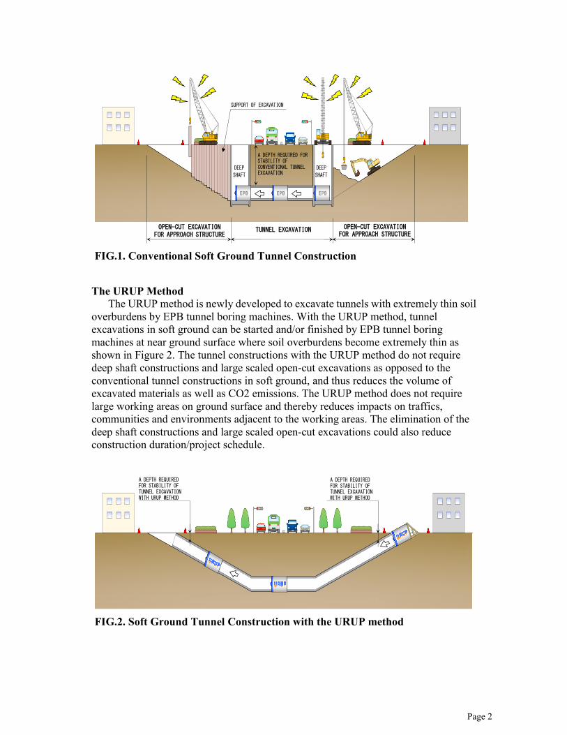
For conventional tunnel constructions in soft ground, vertical shafts are constructed to maintain deep soil overburdens above tunnel excavations for ground stability and large scaled open-cut excavations are carried out to construct approach structures as shown Figure 1. The deep vertical shaft constructions and the large scaled over-cut excavations generate a significant amount of excavated materials. Large CO2 emissions are also generated due to haulage of the excavated materials. These activities require large working area on the ground surface which impact traffic, community and the adjacent environment.
Page 2
The URUP Method
The URUP method is newly developed to excavate tunnels with extremely thin soil overburdens by EPB tunnel boring machines. With the URUP method, tunnel excavations in soft ground can be started and/or finished by EPB tunnel boring machines at near ground surface where soil overburdens become extremely thin as shown in Figure 2. The tunnel constructions with the URUP method do not require deep shaft constructions and large scaled open-cut excavations as opposed to the conventional tunnel constructions in soft ground, and thus reduces the volume of excavated materials as well as CO2 emissions. The URUP method does not require large working areas on ground surface and thereby reduces impacts on traffics, communities and environments adjacent to the working areas. The elimination of the deep shaft constructions and large scaled open-cut excavations could also reduce construction duration/project schedule.
FIG.2. Soft Ground Tunnel Construction with the URUP method
OPEN-CUT EXCAVATION FOR APPROACH STRUCTURE
TUNNEL EXCAVATION
OPEN-CUT EXCAVATION FOR APPROACH STRUCTURE
FIG.1. Conventional Soft Ground Tunnel Construction
A DEPTH REQUIRED FOR STABILITY OF TUNNEL EXCAVATION WITH URUP METHOD

Page 3
EXPERIMENTAL TUNNEL CONSTRUCTION
Digging a tunnel through a sand castle on the beach becomes more challenging when the sand castle gets shorter as shown in Figure 3. The same can be said of the URUP method because tunnel excavations by EPB tunnel boring machines will be started and/or finished at near ground surface where soil overburdens above tunnels become extremely thin. To verify that technical challenges imposed by such thin soil overburdens can be overcome by the URUP method, an experimental tunnel is constructed at the Obayashi’s Research & Development Centre. The experimental tunnel is comprised of a 40m underpass section and two (2) 30m approach sections as shown in Figure 4. Depth of soil overburdens above the underpass section varies from 0.65m to 2.2m. A rectangular EPB tunnel boring machine (4,800mm x 2,150mm) shown in Figure 5 is used to excavate the experimental tunnel. The EPB tunnel boring machine is set on a cradle as shown in Figure 6 and 7, and launched to excavate the approach section from near ground surface as shown in Figure 8 and 9. The EPB tunnel boring machine is subsequently advanced through the underpass section to other side of the tunnel as shown in Figure 10 and 11.
FIG.3. Images of Tunnels in Sand Castles
Experimental Tunnel 100m
Approach Section
Approach Section
Underpass Section 30m
40m
30m
Overburden:0.65m (minimum)
Overburden:2.2m (maximum)
Arrival at ground level Launch at ground level
10%
10%
FIG.4. Experimental Tunnel Profile

Page 4
FIG.5. Rectangular EPB Tunnel Boring Machine (4,800mm X 2,150mm)
FIG.6. Cradle and Thrust Frame on Ground Surface
FIG.7. EPB Tunnel Boring Machine’s Launching at Ground Surface
FIG.9. Excavation of Approach Section
FIG.8. EPB Tunnel Boring Machine’s Excavation at Ground Surface

Page 5
Rectangular segmental steel linings (4,656mm x 2,006mm) are erected as the EPB tunnel boring machine is advanced. A void between the steel lining and ground overcut by the EPB tunnel boring machine is filled with cement grout to avoid excessive settlements on ground surface as shown in Figure 12. All the surface settlements observed above the underpass section remain within +/-10mm as shown in Figure 13. On the completion of the experimental tunnel excavation, the underpass section is unearthed to confirm that all tail voids around the steel linings have been completely filled with cement grout as shown in Figure 14, 15, 16 and 17.
FIG.10. Excavation of Underpass Section
FIG.11. EPB Tunnel Boring Machine’s Arrival at Ground Surface
S
ett
lem
ent (
mm
)
FIG.13. Ground Surface Settlements above Underpass Section
FIG.12. Concept of Tail Void Grout
Tail Void 72mm
Steel Segmental
Lining
Grout
EPB Tunnel Boring Machine

Page 6
THE URUP METHOD APPLICATION TO TUNNEL PROJCTS The Oi Area Tunnel Construction Project
The URUP method is adopted for the first time in the Oi Area Tunnel Construction Project in Japan. The project is a part of the construction of Metropolitan Expressway Central Circular Shinagawa Route as shown in Figure 19. Two (2) tunnels, Ohashi-bound tunnel and Oi-bound tunnel, are constructed
FIG.14. Unearthed Underpass Section
90mm
FIG.15. Tail Void Grout (Top)
105mm
FIG.16. Tail Void Grout (Side)
80mm
FIG.17. Tail Void Grout (Bottom)
FIG.18.Overview of the Oi Area Tunnel Construction Project

Page 7
for transitions of the inbound and outbound expressways from ground surface to underground as shown in Figure 18. Project data of the Oi Area Tunnel Construction Project is summarized in Table 1.
Table 1. A Summary of The Oi Area Tunnel Construction Project
Project Owner Tokyo Metropolitan Government Project Duration June 25, 2008 to November 30, 2011 Tunneling Method Earth Pressure Balance method
(URUP method) TBM Data Excavation Diameter: 13.6m
Tunnel Length: Total 886m Ohashi-bound (The 1st drive): 550m Oi-bound (The 2nd drive): 336m
Lining Data Outside Diameter: 13.4m Inside Diameter: 12.5m Segment Width: 1,700mm
Other Structures Ventilation Station (TBM receiving / U-turn shaft) constructed by Pneumatic Caisson method 39 m × 35 m × 44 m (depth)
The construction sequence of the Oi Area Tunnel Construction Project is described
below and also shown in Figure 20:
Step 1 The EPB tunnel boring machine is launched at near ground surface to start the
excavation of the Ohashi-bound tunnel as shown in Figure 21 and 22, and advanced to the shaft that has been built for the Oi Kita ventilation station structure.
Step 2
The EPB tunnel boring machine is turned around within the ventilation shaft and
FIG.19. Project Map (by courtesy of the Tokyo Metropolitan Government and Metropolitan Expressway Co., Ltd)
Ohashi JunctionOi Junction
Oi Area Tunnel construction project
Yashio 3-chome,Shinagawa-ku
Aobadai 4-chome,Meguro-ku
Length : approx. 9.4km
Central Circular Shinagawa Route
Central C
ircular Shinjuku R
oute
Route
3(Shib
uya R
oute
)
Bay S
hore
Route
Ohashi JunctionOi Junction
Oi Area Tunnel construction project
Yashio 3-chome,Shinagawa-ku
Aobadai 4-chome,Meguro-ku
Length : approx. 9.4km
Central Circular Shinagawa Route
Central C
ircular Shinjuku R
oute
Route
3(Shib
uya R
oute
)
Bay S
hore
Route

Page 8
lifted up to the elevation at which the excavation of the Oi-bound tunnel is started as shown in Figure 23 and 24.
Step 3
The EPB tunnel boring machine is relaunched to start the excavation of the Oi-bound tunnel and advanced to ground surface level as shown in Figure 25 and 26.
Shield machineOi-kita
Ventilation StationArrival at ground level
Launching at ground level
①Construction of Ohashi-bound tunne
l③Construc
tion of Oi-bound tunnel
②Turning around and raisingthe shield machine
Shield machineOi-kita
Ventilation StationArrival at ground level
Launching at ground level
①Construction of Ohashi-bound tunne
l③Construc
tion of Oi-bound tunnel
②Turning around and raisingthe shield machine
FIG.20. Construction Sequence of the Oi Area Tunnel Construction Project
FIG.22.Launching at Ground Surface FIG.21.Tunnel Boring Machine
FIG.24. Lift-Up in a Shaft FIG.23. U-Turn in a Shaft

Page 9
The Tahara 2nd Line Mikawa Bay Crossing Tunnel Project
The Tahara 2nd Line Mikawa Bay Crossing Tunnel Project involves construction of a tunnel for installation of a new gas conduit underneath the seabed of the Mikawa Bay as shown in Figure 27. The project data is summarized in Table 2. Two (2) deep vertical shafts were originally envisioned at both the tunnel ends for an EPB tunnel boring machine to be launched and received respectively. However, the URUP method is proposed and adopted as the final plan as shown in Figure 28, considering the following advantages:
FIG.25. Surface Arrival (before) FIG.26. Surface Arrival (after)
Sea
Launching from Ground Surface
Arrival at Ground Surface
FIG.27. Overview of the Tahara 2nd Line Mikawa Bay Crossing Tunnel Project

Page 10
Table 2. A Summary of Tahara 2nd LineMikawa Bay Crossing Tunnel Project
Project Owner CHUBU GAS CO.,LTD. Project Duration June 17, 2010 to November 30, 2011 Tunneling Method Earth Pressure Balance Method
(URUP method) TBM Data Excavation Diameter: 2.13m
Tunnel Length: Total 1,086.7m Lining Data Outside Diameter: 1.956m
Inside Diameter: 1.8m Segment Width: 750mm
No Shaft Construction /No Ground Improvement
The tunnel excavation by the EPB tunnel boring machine is started and finished at near ground surface as shown in Figure 29 and 30. Thereby, both the 23.5m deep vertical shafts envisioned in the original plan are eliminated. Ground improvements required to remove the shaft walls for the EPB tunnel boring machine’s launching and receiving are also eliminated.
Mikawa Bay
Surface Launching
Surface Arrival
-15% -14%
Level
EPB Method (Conventional Launching/Arrival) L=937.2m Open Cut 130m Open Cut
Open Cut
EPB Method (URUP Launching/Arrival) L=1,086.7m Open Cut Open Cut Proposed Original
Receiving Shaft φ=4m
Launching Shaft φ=12.0m
23.7m
23.5m」「
5.5m ▽Future Channel
▽ Existing Channel
▽H.W.L ▽L.W.L
FIG.28. Comparison of Original/Proposed Tunnel Profiles
FIG.29.Surface Launching FIG.30. Surface Arrival
Page 11
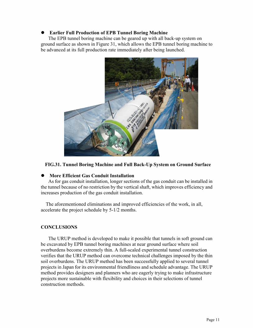
Earlier Full Production of EPB Tunnel Boring Machine The EPB tunnel boring machine can be geared up with all back-up system on
ground surface as shown in Figure 31, which allows the EPB tunnel boring machine to be advanced at its full production rate immediately after being launched. More Efficient Gas Conduit Installation
As for gas conduit installation, longer sections of the gas conduit can be installed in the tunnel because of no restriction by the vertical shaft, which improves efficiency and increases production of the gas conduit installation.
The aforementioned eliminations and improved efficiencies of the work, in all,
accelerate the project schedule by 5-1/2 months. CONCLUSIONS
The URUP method is developed to make it possible that tunnels in soft ground can be excavated by EPB tunnel boring machines at near ground surface where soil overburdens become extremely thin. A full-scaled experimental tunnel construction verifies that the URUP method can overcome technical challenges imposed by the thin soil overburdens. The URUP method has been successfully applied to several tunnel projects in Japan for its environmental friendliness and schedule advantage. The URUP method provides designers and planners who are eagerly trying to make infrastructure projects more sustainable with flexibility and choices in their selections of tunnel construction methods.
FIG.31. Tunnel Boring Machine and Full Back-Up System on Ground Surface

Page 12
ACKNOWLEDGEMENTS
The authors would like to thank the Tokyo Metropolitan Government and Chubu Gas Company CO., LTD. for their support in publishing this paper. Any opinions, findings and conclusions stated in this paper are those of the authors and do not necessarily reflect the views of the Tokyo Metropolitan Government or Chubu Gas Company CO., LTD. REFERENCES Tanaka, Yamauchi, Nonaka (2011), “URUP (Ultra Rapid Underpass)-TBM
Excavation in Soft Ground From The Surface Elevation (Zero Overburden) Without Shaft and/or Large Scaled Open Cut Pit”, Rapid Excavation Tunnel Conference, San Francisco, USA, June 2011.
Fujiki, Nakamura, Izawa (2010), “URUP (Ultra Rapid under Pass) Method – The First Implementation in the World”, World Tunnel Congress, Vancouver, Canada, May 2010.
Hayashi, Miki, Yokomizo, Yoshida, Izawa (2006), “The demonstration work of URUP method”, Proceedings of the 61st Annual Conference of Japan Society of Civil Engineers.
Izawa, Miki, Yokomizo, Yoshida, Hayashi (2006), “The outline of the development of URUP method”, Proceedings of the 61st Annual Conference of Japan Society of Civil Engineers.
Miki, Yokomizo, Ueda, Hino, Yamamoto (2009), “Development of Construction Method for a Road Underpass at Intersection”, World Tunnel Congress, Budapest, Hungary, May 2009.


![Innovative Use of Ultra-High Performance Concrete for ... · PDF fileTitle: Microsoft PowerPoint - MurrayP-Hodder Avenue Underpass-Version 2 [Compatibility Mode] Author: GUO850196](https://img.dokumen.tips/doc/110x75/5ab863e87f8b9ab62f8c9903/innovative-use-of-ultra-high-performance-concrete-for-microsoft-powerpoint-.jpg)