Embed Size (px)
Citation preview

SMALL-SCALE WIND POWER


SMALL-SCALE WIND POWER
Design, AnAlysis, AnD environmentAl impActs
JOHN ABRAHAM AND BRIAN PLOURDE
MOMENTUM PRESS, LLC, NEW YORK

Small-Scale Wind Power: Design, Analysis, and Environmental ImpactsCopyright © Momentum Press®, LLC, 2014.
All rights reserved. No part of this publication may be reproduced, stored in a retrieval system, or transmitted in any form or by any means— electronic, mechanical, photocopy, recording, or any other—except for brief quotations, not to exceed 400 words, without the prior permission of the publisher.
First published by Momentum Press®, LLC222 East 46th Street, New York, NY 10017www.momentumpress.net
ISBN-13: 978-1-60650-484-0 (print)ISBN-13: 978-1-60650-485-7 (e-book)
Momentum Press Environmental Engineering Collection
DOI: 10.5643/9781606504857
Cover design by Jonathan PennellInterior design by Exeter Premedia Services Private Ltd., Chennai, India
10 9 8 7 6 5 4 3 2 1
Printed in the United States of America

AbstrAct
In today’s world, clean and robust energy sources are being sought to provide power to residences, commercial operations, and manufacturing enterprises. Among the most appealing energy sources is wind power—with its high reliability and low environmental impact.
Wind power’s rapid penetration into markets throughout the world has taken many forms. In some cases, wind power is produced in large industrial wind farms by large horizontal-axis wind turbines (HAWTs) that supply power directly to the grid. In other cases, wind power is pro-duced more locally, at or near the site of power usage. In these cases, the wind is typically generated by smaller wind turbines that are in single-unit installations or in clusters of units. Regardless of the manifestation of the wind turbine systems, much thought must be given to the selection of the turbine, the economic viability of the installation, and the integration of the system to the connecting grid.
It is the intention of this text to discuss these issues in detail so that appropriate decisions can be made with respect to wind power design, testing, installation, and analysis. The specific focus is on small-scale wind systems. While there is no universal definition of small-scale wind power, it generally refers to systems that produce only a few kilowatts, can be installed in constrained spaces, and have a small footprint.
The text is written for a wide range of audiences and much of the discussion deals with the design of various small-wind systems, including horizontal-axis wind turbines (HAWTs) and vertical-axis wind turbines (VAWTs). Both of which will be discussed in detail.
The design of wind turbines takes advantage of many avenues of investigation, all of which are included here. Analytical methods that have been developed over the past few decades are major methods used for design. Alternatively, experimentation (typically using scaled models in wind tunnels) and numerical simulation (using modern computational fluid dynamic software) are also used and will be dealt with in depth in later chapters.
In addition to the analysis of wind turbine performance, it is important for users to assess the economic benefits of using wind power, therefore,

an entire chapter of this book is devoted to this topic. Finally, the deci-sion to utilize wind power can take advantage of past experience gained through case studies. Such case studies help elucidate the issues that users must consider, from siting and mechanical complications, to performance and maintenance. Experience gained from case studies will be showcased here.
This text is intended to be useful to engineers, scientists, wind-power users, installers, and investors. It is written in part as a hands-on guide and a development tool. The authors are leading contributors from around the world, collectively, they represent the present state-of-the-art with respect to small wind power.
KEYWORDS
clean energy, Darrieus wind turbines, horizontal-axis wind turbines, local power production, off-grid energy generation, remote wind power, renew-able energy, Savonius wind turbines, small-scale wind power, sustainable energy, turbine blades, turbine rotors, urban wind generation, vertical-axis wind turbine, wind turbine aerodynamics, wind turbine rotor design, wind turbines
contents
List of figures vii
List of Contributors ix
Chapter 1 introduCtion to smaLL-sCaLe Wind poWer 1
Chapter 2 finanCiaL and impLementation Considerations of smaLL-sCaLe Wind turbines 17
Chapter 3 design of darrieus-styLe Wind turbines 45
Chapter 4 design of savonius-styLe Wind turbines 65
Chapter 5 design of horizontaL-axis Wind turbines 93
Chapter 6 numeriCaL simuLations of smaLL Wind turbines—haWt styLe 129
Chapter 7 Case studies of smaLL Wind appLiCations 147
index 173
vii


list of figures
Figure 1.1. A small-scale VAWT wind-power system attached to a cellular communication tower. 4
Figure 1.2. Close-up photograph showing a small-scale turbine with support brackets and positioning of electrical generator. 5
Figure 1.3. Photograph of an array of vertical-axis Darrieus-style turbines. 5
Figure 1.4. Close-up photograph of the rotors of a Darrieus-style VAWT. 6
Figure 1.5. Close-up photograph of a propeller HAWT. 7Figure 1.6. Rotating HAWT rotor with contoured blades. 8Figure 1.7. Photograph of a Darrieus VAWT connected to a
solar panel, positioned in a constrained urban location. 10Figure 1.8. Annual average wind speeds at 30 m height
across the United States. 12Figure 1.9. Annual average wind speeds at 80 m height
across the United States. 12Figure 1.10. Annual average offshore wind speeds in regions
surrounding the United States. 13Figure 1.11. Average wind speeds across China, 70 m height. 14Figure 2.1. A computer rendering of a small-scale Savonius
VAWT rotor. 19Figure 2.2. Images of small-scale HAWT. 21Figure 2.3. Small-scale VAWT on Lincoln Financial Field. 22Figure 2.4. Power Curve for small-scale wind turbine with
a sweet area of 5 m2 and a Cp of 0.2. 24
x • LiSt Of figuRES
Figure 2.5. A small-scale wind turbine designed for telecommunication base transceiver stations during installation on U.S. Department of Transportation telecommunication tower. 27
Figure 2.6. Power curve for small-scale wind turbine with a swept area of 6 m2 and Cp of 0.3. 36
Figure 2.7. Average wind speed map of Kenya. 37Figure 3.1. Darrieus Rotor Near Heroldstatt in Germany. 46Figure 3.2. Straight-bladed Darrieus VAWT (SB-VAWT). 47Figure 3.3. Flow velocities of SB-VAWT. 55Figure 3.4. Force diagram for a blade airfoil. 56Figure 4.1. Two-bladed “S”-shaped and helical-shaped
Savonius-style vertical-axis wind turbines. 66Figure 4.2. Dimensions of a Savonius-style vertical-axis
wind turbines. 67Figure 4.3. Historic Gold Mine Savonius-Darrieus combined
small-scale vertical-axis turbine in Taiwan (November, 2009). 68
Figure 4.4. Various flow patterns around a Savonius-style wind turbine, (I: Free stream flow, II: Coanda type flow, III: Dragging-type flow, IV: Overlapping flow, V: Separation flow, VI: Stagnation flow, VII: Returning flow, VIII: Vortex flow). 70
Figure 4.5. Power coefficient of Savonius-style “S”-shaped wind turbines along with other counterparts. 71
Figure 4.6. Torque coefficient of Savonius-style “S” shaped
wind turbines along with other counterparts. 71
Figure 4.7. Savonius-style turbines. 74Figure 4.8. Darrieus-style turbines. 74Figure 4.9. Examples of Savonius-style turbines with
different aspect ratios and overlap ratios. 75Figure 4.10. Effect of overlap ratio on the performance
of Savonius-style wind turbines. 76Figure 4.11. Application of end plates and multi-staging in to
the design of Savonius-style wind turbines. 77Figure 4.12. Effect of multi-staging on the torque performance
of Savonius-style wind turbine. 78
LiSt Of figuRES • xi
Figure 4.13. Comparative analysis of two and three-bladed Savonius-style turbines. 79
Figure 4.14. Demonstration of most common Savonius-style blade profiles patented by Savonius and Benesh. 80
Figure 4.15. Optimized blade profile of Savonius-style turbine 80Figure 4.16. Application of Savonius style wind turbines in
communication towers with a modified blade profile. 81Figure 4.17. A twisted bladed Savonius-style vertical-axis
wind turbine “Gale” by Tangarie. 82Figure 4.18. Photograph of a 3 kW helical vertical-axis wind turbine 83Figure 4.19. Close-up photograph showing testing of
conventional Savonius-style turbines in a wind tunnel with open test section facility. 83
Figure 4.20. Testing of Savonius-style helical wind turbines in a wind tunnel with a closed test section. 84
Figure 4.21. Effect of blockage on the performance of Savonius-style wind turbine. 85
Figure 4.22. Design and dimensions of a Savonius-style wind turbine. 88
Figure 5.1. Rotor power coefficient as a function of tip speed ratio for various rotor configurations 94
Figure 5.2. Components of a small HAWT. 96Figure 5.3. Schematic of a teetering mechanism. 97Figure 5.4. Small HAWT installed on the rooftop of
the Western University Engineering building. 98Figure 5.5. Sky Serpent design installed in Tehachapi, California 99Figure 5.6. Typical power curve of small HAWTs. 100Figure 5.7. Wind turbine rotor modeled by an actuator disc. 103Figure 5.8. Schematic of the rotating actuator disc with an
annular ring of radius r. 106Figure 5.9. Tangential velocity changes across the rotor disc. 107Figure 5.10. Theoretical maximum power coefficient as a function
of tip speed ratio for an ideal HAWT with and without wake rotation. 108
Figure 5.11. Blade geometry for blade element analysis. 109Figure 5.12. Blade element geometry, velocities, and forces. 110
xii • LiSt Of figuRES
Figure 5.13. BEM prediction of power output compared with wind tunnel measurements. 113
Figure 5.14. Comparison between experimental results and BEM theory prediction with and without tip loss corrections. 115
Figure 5.15. Effect of stall delay correction on the rotor performance prediction by BEM. 116
Figure 5.16. Lift and drag coefficients for FX 63 137 airfoil obtained through wind tunnel testing and JavaFoil. 119
Figure 5.17. Schematic drawing of a vehicle-based wind turbine prototype testing setup. 121
Figure 5.18. Wind tunnel test setup of a small HAWT. 122Figure 5.19. Power coefficient variation with tip speed ratio
for a three-bladed HAWT. 123Figure 5.20. Comparison of experimental and theoretical power
coefficients. 124Figure 5.21. The theoretical and experimental power curve of
the rotor for a wide range of wind speeds. 125Figure 5.22. Percentage of difference between predicted power
by BEM theory and the measured power. 126Figure 6.1. Streamline patterns from a small horizontal axis
wind turbine by CFD simulation. 135Figure 6.2. Schematic of wind profile. 135Figure 6.3. Meshing for wind turbine blade and rotor
CFD simulation. 137Figure 6.4. Meshing for entire wind turbine system
CFD simulation. 138Figure 6.5. Pressure coefficient (Cp) on the blade surface
along the entire blade length. 143Figure 6.6. Power curves for typical 10 kW HAWT. 143Figure 7.1. View of the Rasoon camp. 149Figure 7.2. View of the 2 kW wind turbine. 150Figure 7.3. The connection diagram of the 2 kW wind system. 150Figure 7.4. Electrical wind pump. 153Figure 7.5. Naima project equipment layout. 154Figure 7.6. Wind turbine installed at Heelat Ar Rakah. 156

LiSt Of figuRES • xiii
Figure 7.7 The 65 kW wind turbine installed in Appalachia, Wales, Alaska. 157
Figure 7.8. The 900 W wind turbine on hillside above Douglas County home. 160
Figure 7.9 Monthly average wind speed at Alasfar site. 161Figure 7.10 Monthly power consumption of Alasfar site. 162Figure 7.11. PLC Module and touch screen for easy turbine control. 162Figure 7.12. Free standing tower for 20 kW wind turbine. 163Figure 7.13. Power curve of 20 kW wind turbine installed at
Alasfar site. 165Figure 7.14. Probability distribution function for the wind at
the considered site. 166Figure 7.15. A view of Al-Ibrahimiyah wind farm. 168Figure 7.16. Small wind farm near the community
of Ramea, Canada. 169


list of contributors
J.P. Abraham, University of St. Thomas, School of Engineering, St. Paul, MN, USA
M.H. Alzoubi, Yarmouk University, Irbid, Jordan
H. Hangan, Western University, WindEEE Research Institute, London, Ontario, Canada
M. Islam, Department of Mechanical and Manufacturing Engineering, Schulich School of Engineering, University of Calgary, Alberta, Canada
W.J. Minkowycz, University of Illinois, Chicago, Department of Mechan-ical and Industrial Engineering, Chicago, IL, USA
P.O. Okaka, Kenyatta University, Mechanical Engineering Department, Nairobi, Kenya
B.D. Plourde, University of St. Thomas, School of Engineering, St. Paul, MN, USA
M. Refan, Western University, WindEEE Research Institute, London, Ontario, Canada
S. Roy, Indian Institute of Technology Guwahati, Department of Mechan-ical Engineering, Guwahati–781039, India
U.K. Saha, Indian Institute of Technology Guwahati, Department of Mechanical Engineering, Guwahati–781039, India
E.D. Taylor, University of St. Thomas, School of Engineering, St. Paul, MN, USA
J.C.K. Tong, University of Minnesota, MN, USA

CHAPtER 1
introDuction to smAll-scAle WinD poWer
B.D. Plourde, E.D. Taylor, W.J. Minkowycz, and J.P. Abraham
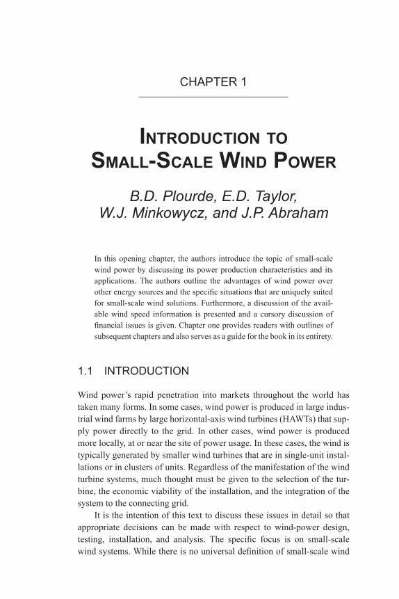
In this opening chapter, the authors introduce the topic of small-scale wind power by discussing its power production characteristics and its applications. The authors outline the advantages of wind power over other energy sources and the specific situations that are uniquely suited for small-scale wind solutions. Furthermore, a discussion of the avail-able wind speed information is presented and a cursory discussion of financial issues is given. Chapter one provides readers with outlines of subsequent chapters and also serves as a guide for the book in its entirety.
1.1 iNtRODuCtiON
Wind power’s rapid penetration into markets throughout the world has taken many forms. In some cases, wind power is produced in large indus-trial wind farms by large horizontal-axis wind turbines (HAWTs) that sup-ply power directly to the grid. In other cases, wind power is produced more locally, at or near the site of power usage. In these cases, the wind is typically generated by smaller wind turbines that are in single-unit instal-lations or in clusters of units. Regardless of the manifestation of the wind turbine systems, much thought must be given to the selection of the tur-bine, the economic viability of the installation, and the integration of the system to the connecting grid.
It is the intention of this text to discuss these issues in detail so that appropriate decisions can be made with respect to wind-power design, testing, installation, and analysis. The specific focus is on small-scale wind systems. While there is no universal definition of small-scale wind
2 • SMALL-SCALE WiND POWER
power, it generally refers to systems that produce up to a few kilowatts and can be installed in constrained spaces and with a small footprint.
The text is written to be of use to a wide range of audiences. Much of the discussion contained herein deals with the design of various small-wind systems including HAWTs and vertical-axis wind turbines (VAWTs). Among the vertical-axis variants are two major classifica-tions: Darrieus and Savonius-style rotors. The former is often colloquially referred to as the egg-beater turbine because of its shape. The latter is often, but not always, fashioned from a cylindrical drum that is bisected with the two halves offset some distance from a common rotation axis. The Darrieus-style turbine has its rotation caused by lift forces, whereas the Savonius-style turbine is driven by drag. Both of these classes will be discussed in detail.
The design of wind turbines takes advantage of many avenues of investigation, all of which are included here. Analytical methods, which have been developed over the past few decades, are one major method used for design. Alternatively, experimentation (typically using scaled models in wind tunnels) and numerical simulation (using modern com-putational fluid dynamic software) are also used and will be dealt with in depth in later chapters.
In addition to the analysis of wind turbine performance, it is important for users to assess the economic benefits of using wind power. An entire chapter of this book is devoted to this topic. Finally, the decision to utilize wind power can take advantage of past experience gained through case studies. Such case studies help elucidate the issues that users must consider, from siting and mechanical complications to performance and mainte-nance. Experience gained from case studies will be showcased in this book.
This text is intended to be useful to engineers, scientists, wind-power users, installers, and investors. It is written partly as a hands-on guide and partly as a development tool. The authors are leading contributors from around the world. Collectively, they represent the present state-of-the-art with respect to small-wind power.
1.2 WHAt iS SMALL-SCALE WiND POWER?
As indicated earlier, small-scale wind power is wind energy that is gen-erated at the site of utilization and is typically in the few kilowatt range. Small-scale wind turbines are often connected directly to the devices that require electricity, or more commonly, to a power charging station such as a battery array. The necessity of an energy storage system is obvious when

iNtRODuCtiON tO SMALL-SCALE WiND POWER • 3
the intermittency of wind power is recognized. It is often the case that power is available when not needed by the user, or conversely, electricity is needed but not yet generated. Storage systems help alleviate this condi-tion by storing excess energy for later use.
Small-scale wind power is often combined with complementary energy sources. For instance, the combination of small-scale wind with solar power allows energy to be generated more consistently, when either sunlight or wind is present. Other combinations include small-scale wind power with more conventional energy sources (such as diesel generators) that can be used to guard against scenarios when more energy is required by the user than is supplied by the system.
Regardless of the actual manifestation, whether a stand-alone wind turbine or a wind turbine combined with a complementary power source, the electronic infrastructure must be given some consideration. The elec-tronic components and systems for small-scale wind turbines have been active areas of research [1–5].
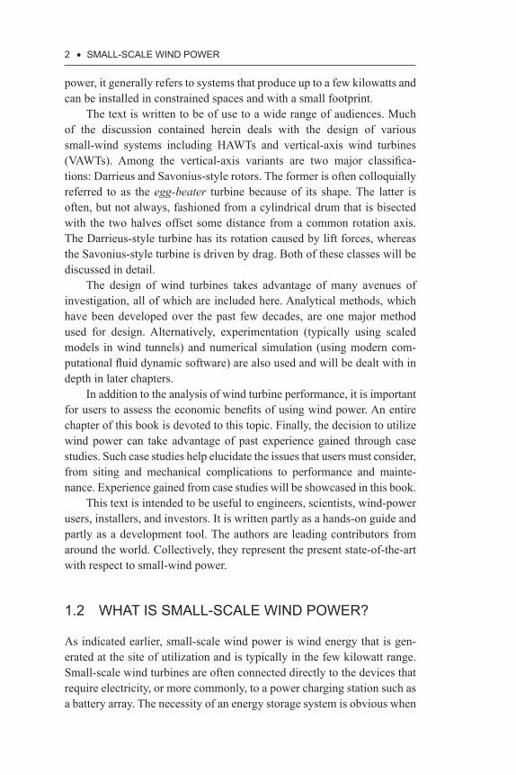
An example of a small-scale wind-power system is shown in Fig-ure 1.1. The VAWT turbine is shown positioned to the left-hand side of a communication tower at an elevation of approximately 50 m. The turbine rotors are staged (three stages) and oriented approximately 60° from their neighbor. Staged orientation of VAWTs helps to guard against stalling, mechanical vibrations, and cyclical variations in power.
A close-up view of the wind turbine is shown in Figure 1.2. There, it is seen that the turbine in question is a drag device (Savonius-style tur-bine). These devices are typically large curved surfaces that are contoured to create unequal forces on their two opposing sides so that there is a net torque about the central axis. The photographs shown in Figures 1.1 and 1.2 are meant to provide some information on the physical size of small-scale turbines. Turbines within this category are typically a fraction of a meter to a few meters in dimension, depending on the specific system.
The examples illustrated in Figures 1.1 and 1.2 are stand-alone tur-bines. In some situations, however, turbines can be used in collections. An example of a wind turbine array is shown in Figure 1.3. In this figure, a multitude of Darrieus-style turbines can be seen, each of which rotates about a vertical axis. The study from which the figure originated was focused on developing an understanding of how disturbances in air flow created by one turbine might impact the performance of a neighbor [8,9].
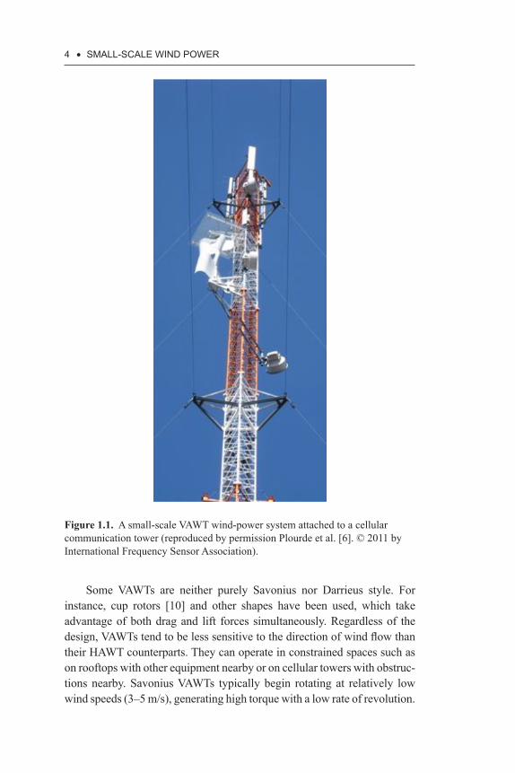
Another variation of this Darrieus style is shown in Figure 1.4. There, three airfoils are clearly seen, which are able to rotate about a vertical axis. They are driven by lift forces exerted on the rotor by the wind, similar to the forces that act on an airplane wing.
4 • SMALL-SCALE WiND POWER
Figure 1.1. A small-scale VAWT wind-power system attached to a cellular communication tower (reproduced by permission Plourde et al. [6]. © 2011 by International Frequency Sensor Association).
Some VAWTs are neither purely Savonius nor Darrieus style. For instance, cup rotors [10] and other shapes have been used, which take advantage of both drag and lift forces simultaneously. Regardless of the design, VAWTs tend to be less sensitive to the direction of wind flow than their HAWT counterparts. They can operate in constrained spaces such as on rooftops with other equipment nearby or on cellular towers with obstruc-tions nearby. Savonius VAWTs typically begin rotating at relatively low wind speeds (3–5 m/s), generating high torque with a low rate of revolution.

iNtRODuCtiON tO SMALL-SCALE WiND POWER • 5
Protectiveplate
Three-stagerotor
Generator
Support bracket
Figure 1.2. Close-up photograph showing a small-scale turbine with support brackets and positioning of an electrical generator (reproduced by permission from Abraham et al. [7]. © 2011 by AIP Publishing LLC).
Figure 1.3. Photograph of an array of vertical-axis Darrieus-style turbines.
Source: Courtesy of John O. Dabiri/California Institute of Technology [8,9].
6 • SMALL-SCALE WiND POWER
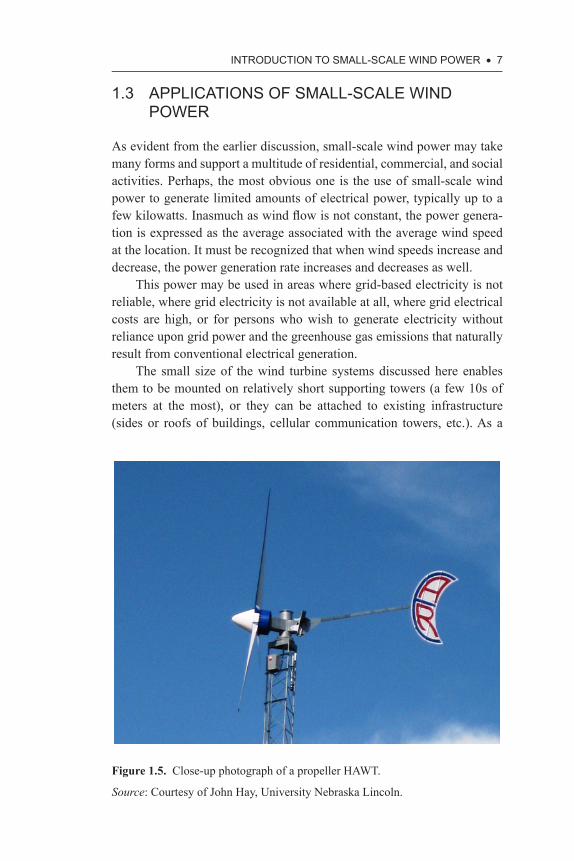
Despite these characteristics, the most commonly encountered small-scale wind turbine is the HAWT style. The reason for this is the higher efficiency of most HAWTs and the simplicity of installation. A photograph showing a typical small HAWT is presented in Figure 1.5. These turbines are smaller versions of the propeller-style large grid-connected turbines.
A second figure showing a small-scale HAWT with a curved rotor is provided in Figure 1.6. In some instances, contouring of blades allows more careful control of the relative velocity between the wind and the rotor at each location along the length of the rotor arm. As with large grid-level HAWTs, the shape, width, and angle of the blades should be carefully designed because the relative velocity between the wind and the rotor blade varies with the distance from the axis of rotation—details of the design methodology associated with HAWTs are given in Chapter 5.
Figure 1.4. Close-up photograph of the rotors of a Darrieus-style VAWT.
Source: Courtesy of Aeolos Wind Energy, Ltd (http://www.windturbinestar.com/).
iNtRODuCtiON tO SMALL-SCALE WiND POWER • 7
1.3 APPLiCAtiONS Of SMALL-SCALE WiND POWER
As evident from the earlier discussion, small-scale wind power may take many forms and support a multitude of residential, commercial, and social activities. Perhaps, the most obvious one is the use of small-scale wind power to generate limited amounts of electrical power, typically up to a few kilowatts. Inasmuch as wind flow is not constant, the power genera-tion is expressed as the average associated with the average wind speed at the location. It must be recognized that when wind speeds increase and decrease, the power generation rate increases and decreases as well.
This power may be used in areas where grid-based electricity is not reliable, where grid electricity is not available at all, where grid electrical costs are high, or for persons who wish to generate electricity without reliance upon grid power and the greenhouse gas emissions that naturally result from conventional electrical generation.
The small size of the wind turbine systems discussed here enables them to be mounted on relatively short supporting towers (a few 10s of meters at the most), or they can be attached to existing infrastructure (sides or roofs of buildings, cellular communication towers, etc.). As a
Figure 1.5. Close-up photograph of a propeller HAWT.
Source: Courtesy of John Hay, University Nebraska Lincoln.

8 • SMALL-SCALE WiND POWER
consequence of their positioning in urban or rural areas where spaces may be constrained and where obstructions to wind flow exist, small-scale wind systems tend to be less dependent on wind speed, turbulence levels, and wind direction than their large grid-level counterparts. These general abilities, however, do not obviate the need for proper siting because insuf-ficient wind strength or poor wind quality can render a small-scale wind-power system economically nonviable.
Wind-power systems that are used in residential locations are able to provide significant portions of the home electrical requirements. This is particularly true if the system is accompanied by a system that allows the storage of energy when it is generated but not needed by the resident. The stored energy is then drawn down during times of electrical demand. In some geographic locations, in particular, in many U.S. states, residences are allowed to generate and sell electricity to the grid supplier. In such a situation, the wind-power system can be used to generate revenue.
For commercial uses, wind turbines can power any number of elec-trical demands including lighting, charging of electrical appliances, and powering office equipment, to name a few. There are other less obvious uses such as providing electricity for cellular communication equipment or for water pumps in remote locations, for example. In addition to electri-cal generation, the mechanical energy of a small-scale wind turbine can be used directly to lift, turn, or move objects. While direct use of mechanical
Figure 1.6. Rotating HAWT rotor with contoured blades.
Source: Courtesy of John Hay, University Nebraska Lincoln.

iNtRODuCtiON tO SMALL-SCALE WiND POWER • 9
energy avoids inevitable losses in the electrical system and can be quite efficient, it is not discussed in much detail here because of the focus on electrical energy generation.
1.4 ADVANtAgES Of SMALL-SCALE WiND OVER COMPEtiNg ENERgY SOuRCES
Wind power in general, and small-scale wind power in particular, has a number of features that make it an attractive option for individuals, com-panies, and other institutions that require power. Perhaps, the most obvi-ous feature is that wind-power systems provide electricity and mechanical energy without reliance on grid-level power systems. Consequently, they provide a level of availability that is often not achieved with grid power, particularly in the developing world.
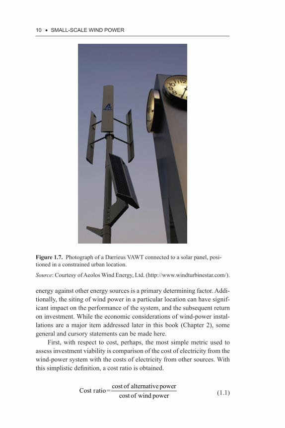
Second, wind power can be made available at locations that cannot be connected to the grid. These locations, which are often remote, must gen-erate their own electricity and wind should be considered a competitive option. Third, wind power is particularly suited for complementary appli-cations with other renewable energy sources such as solar power to pro-vide a steady source of power as weather and available sunlight fluctuate. Figure 1.7 shows such a combination of wind–solar systems.
Fourth, wind-power systems can be made to be robust. The mov-ing mechanical pieces, if properly balanced and designed, can withstand environmental abuse and mechanical loads for years without degradation. Finally, since the threat of climate change has gained worldwide atten-tion, it has become increasingly clear that human emissions of greenhouse gases, particularly carbon dioxide, are warming the planet [11–13]. Wind power offers a clean source of electricity. Aside from the costs and emis-sions associated with the construction and erection of a wind turbine, there are no further pollutant emissions. In fact, for some locations around the world, wind-generated electricity can be purchased as an emission offset or the wind energy carbon credits can be sold as an additional revenue stream.
1.5 iSSuES tO CONSiDER PRiOR tO iNStALLiNg WiND POWER
While the advantages of wind power are clear, there are some issues that must be considered in order to determine whether wind power is viable as an energy-generation source. In particular, the cost comparison of wind
10 • SMALL-SCALE WiND POWER
energy against other energy sources is a primary determining factor. Addi-tionally, the siting of wind power in a particular location can have signif-icant impact on the performance of the system, and the subsequent return on investment. While the economic considerations of wind-power instal-lations are a major item addressed later in this book (Chapter 2), some general and cursory statements can be made here.
First, with respect to cost, perhaps, the most simple metric used to assess investment viability is comparison of the cost of electricity from the wind-power system with the costs of electricity from other sources. With this simplistic definition, a cost ratio is obtained.
cost of alternative power
Cost ratio =cost of wind power (1.1)
Figure 1.7. Photograph of a Darrieus VAWT connected to a solar panel, posi-tioned in a constrained urban location.
Source: Courtesy of Aeolos Wind Energy, Ltd. (http://www.windturbinestar.com/).

iNtRODuCtiON tO SMALL-SCALE WiND POWER • 11
Words of caution are advised here. With wind-power systems, the cost is borne during the design and installation phases, which occur prior to power generation. After installation, the system continues to produce power with little continuing investment. In contrast, energy purchased from other sources have costs that may vary with time, but usually within a small range. Consequently, the cost ratio for wind power decreases with each year of operation; so the expected lifetime must be included in the analysis. Second, when small-scale wind power is used, it is possible to avoid the high costs of power loss that might occur during grid-system failures.
A third item to be considered is that the cost of wind power is heavily impacted by the available wind resources. The energy density of wind varies with the cube of the wind velocity so that a doubling of wind speed leads to an eightfold increase in the flow rate of wind energy. With this recognized, it is seen that proper siting of turbines is crucial for their suc-cess. The next chapter will present a more thorough and sophisticated set of performance metrics for wind systems.
Fortunately, wind power maps are available that can guide the siting. For instance, Figures 1.8 and 1.9 show continental wind speeds across the United States at heights of 30 m and 80 m, respectively. A comparison of the figures shows that there is a significant difference in average wind speed for the two heights. This difference often justifies the expense of high-tower construction. Another feature is that the wind speeds are nota-bly higher in the central plains of the United States than on the east or west coasts or downstream from mountain ranges that traverse the western edge of the continent. The central plains are mostly devoid of major blockages to wind flow.
A similar image showing annually averaged wind speeds exclusively for offshore regions is provided in Figure 1.10. It is seen that over water regions, wind speeds are quite high. This generalization also holds for major inland lakes. This behavior is due, in part, to the lack of vertical structures that slow wind near the surface of the Earth. Despite the benefit of higher wind speeds, the installation of a turbine offshore is more com-plex and expensive than on-land sites.
Similar maps are available for other regions of the world. For instance, Figure 1.11 shows typical wind speeds in China. Generic behaviors that were exhibited in the United States maps (Figures 1.8 and 1.9) are seen to prevail worldwide. Generally, air moves slower over land than over water, particularly for land regions that have vertical structures (moun-tains, forests, etc.). There are also global patterns of wind speed that are associated with the general circulation of the atmosphere (Hadley cells, for instance) that lead to more appealing conditions in some regions.

12 • SMALL-SCALE WiND POWER
Figure 1.8. Annual average wind speeds at 30 m height across the United States.
Source: Image courtesy of NREL.
Figure 1.9. Annual average wind speeds at 80 m height across the United States.
Source: Image courtesy of NREL.

iNtRODuCtiON tO SMALL-SCALE WiND POWER • 13
Figure 1.10. Annual average offshore wind speeds in regions surrounding the United States.
Source: Image courtesy of NREL.
Not only are average wind speeds important but so too is the variabil-ity of wind. Turbines perform optimally at steady wind speeds that persist for extended durations. Rapid fluctuations of wind, or large variation of daily, weekly, or monthly wind will lower the overall efficiency of the system and in some cases, require control electronics to allow the turbine to adapt to changes in the environment.
There are many sources of wind speed information such as Truepower LLC, Global Atlas, NREL, among others. Attainment of wind information is essential for successful siting and operation of wind-power systems.
As indicated earlier, this book is intended to serve as a reference to persons who are working in the design and development of small-scale wind turbines, are assessing the potential of small-wind systems to pro-vide electricity for a particular application, are evaluating the economic issues related to small-scale wind power, are servicing or installing wind-power systems, or are hoping to forecast the potential of this technology in general. This book is written for both general and specialized audiences, from the homeowner, to the research and development scientist.
Chapter 2 focuses on the economics of small-scale wind systems with a detailed discussion of the issues that should be considered prior to the purchase and installation of a system.

14 • SMALL-SCALE WiND POWER
Figure 1.11. Average wind speeds across China, 70 m height.
Source: Image courtesy of AWS Truepower LLC.
Next, in Chapter 3, an exposition on the design of Darrieus-style tur-bines is given with a summary of existing designs and a discussion of the design, testing, and performance of modern Darrieus rotors.
In Chapter 4, a parallel description of the current status of Savonius-style turbines is given, along with the design and testing proce-dures and performance measures.
Chapter 5 turns attention to the small-scale HAWTs, which are small versions of the large grid-based wind turbines that are installed around the world.
Chapter 6 describes numerical simulations of small-scale wind tur-bines, with a special emphasis on the HAWT designs. The simulation process uses advanced computational tools, commonly classified as com-putational fluid dynamics (cfd). The justification for the focus on HAWT

iNtRODuCtiON tO SMALL-SCALE WiND POWER • 15
designs (instead of VAWT designs) is that the latter have been extensively covered in the recent literature, which is listed at the end of Chapter 6.
The final chapter, Chapter 7, brings the discussion together in the form of cases studies. Various examples of wind turbine installations have been taken from around the world to assess the performance of the turbine against expectations. The lessons that were learned from those installa-tions are provided.
REFERENCES
[1]. Abraham, J.P., Plourde, B.D., Mowry, G.S., & Minkowycz, W.J. (2012). Summary of Savonius wind turbine development and future applications for small-scale power generation, Journal of Renewable and Sustainable Energy, 4, paper no. 042703.
[2]. Bumby, J.R., & Martin, R. (2005). Axial-flux permanent magnet air-cored generator for small-scale wind turbines, Electric Power Applications, 152(5), 1065–1075.
[3]. Higuchi, Y., Yamamura, N., Ishida, M., & Hori, T. (2000). An improvement of performance for small-scaled wind power generating system with per-manent magnet type synchronous generator, 26th Annual Conference of the IEEE, 1037-1043, October 22–28, 2000, Nagoya.
[4]. Tanaka, T., Toumiya, T., & Suzuki, T. (1997). Output control by hill-climb-ing method for a small-scale wind power generating system, Renewable Energy, 12(4), 387–400.
[5]. Whaley, D.M., Soong, W.L., & Ertugrul, N. (2005). Investigation of switched-mode rectifier for control of small-scale wind turbines, Industry Applications Conference, 40th Annual IAS Meeting, 4, 2849–2856, October 2–6, 2005.
[6]. Plourde, B.D., Abraham, J.P., Mowry, G.S., & Minkowycz, W.J. (2011). Use of small-scale wind energy to power cellular communication equipment, Sensors and Transducers, 13, 53–61, http://www.sensorsportal.com/HTML/DIGEST/P_SI_167.htm.
[7]. Abraham, J.P., Plourde, B.D., Mowry, G.S., & Minkowycz, W.J. (2011). Numerical simulation of fluid flow around a vertical-axis turbine, Journal of Renewable and Sustainable Energy, 3, paper no. 033109.
[8]. Dabiri, J.O. (2011). Potential order-of-magnitude enhancement of wind farm power density via counter-rotating vertical-axis wind turbine arrays, Journal of Renewable Sustainable Energy, 3: paper no. 043104.
[9]. Kinzel, M., Mulligan, Q., & Dabiri, J.O. (2012). Energy exchange in an array of vertical-axis wind turbines, Journal of Turbulence, 13(38), 1–13.
[10]. Mowry, G.S., Erickson, R.A., & Abraham, J.P. (2009). Computational model of a novel two-cup horizontal wind-turbine system, Open Mechanical Engineering Journal, 3, 26–34.

16 • SMALL-SCALE WiND POWER
[11]. Abraham, J.P. et al. (2013). A review of global ocean temperature obser-vations: implications for ocean heat content estimates and climate change, Reviews of Geophysics, 51, 450–483.
[12]. Trenberth, K.E., & Fasullo, J.T. (2010). Tracking Earth’s energy, Science, 328, 316–317.
[13]. Trenberth, K.E., Fasullo, J.T., & Kiehl. J. (2009). Earth’s global energy bud-get, Bulletin of the American Meteorological Society, 90, 311–323.
inDex
AAbraham, J.P., 5Aerodynamic models, 49–50Aerodynamic performance, 51Akwa, J.V., 77, 78Alaska, USA, 156–159American Wind Energy
Association (AWEA), 131Applications
case studies of small wind, 147–171
off-grid small wind systems, 148–160
on-grid wind systems, 160–171of small-scale wind power, 7–9
Aspect ratio, 74–75AWEA. See American Wind
Energy Association
BBarakos, G.N., 143Bazilevs, Y., 137BEM theory. See Blade Element
Momentum theoryBenesh, A.H., 80Betz, A., 103Betz’s limit, 105Beyene, A., 47Bhutta, M.M.A., 47Bianchini, A., 51Blackwell, B.F., 79Blade element geometry, 110
Blade Element Momentum (BEM) theory, 111–113, 134
British Wind Energy Association (BWEA), 131
Burton, T., 107BWEA. See British Wind Energy
Association
CCash flow model, for financial
evaluationinternal rate of return (IRR), 34net present value (NPV), 33–34payback periods (PBPs), 32–33return on investment (ROI), 33total cost of ownership (TCO),
34–35Cellular communication tower, 4CFD. See Computational Fluid
DynamicsCirculation control, 53Clausen, P.D., 95Coanda-type flow, 69, 70Colorado, USA, 159Computational Fluid Dynamics
(CFD), 14, 49, 85, 119, 122, 129
Conventional Savonius-style turbines, 83
coefficient of, 72Costratio, 10Crossflex concept, 53
174 • iNDEX
DDanish Energy Authority (DEA),
131Darrieus and Savonius-style
rotors, 2Darrieus, George Jeans Mary, 45Darrieus–Masgrowe-type wind
turbines, 52–53Darrieus-style turbines, 2, 3, 4Darrieus-style VAWT, 6Darrieus-type vertical-axis wind
turbinesaerodynamic models, 49–50with alternative airfoils, 51–52alternative vertical-axis wind
turbine designs, 51computational methods, 50–51Darrieus–Masgrowe, 52–53design optimization, 49–53design parameters, 48–49experimental investigation, 50helically twisted blade, 52hybrid Darrieus–Savonius
rotor, 52innovative vertical-axis wind
turbine designs, 51orthogonal rotor, 52–53
Darrieus-type wind turbinescurrent designs, 47–48practical darrieus vertical-axis
wind turbine design methodology, 53–56
vertical-axis wind turbines (VAWT), 48–53
DEA. See Danish Energy Authority
Design load cases and external conditions, 131–134
Design parameters, of Savonius-style turbines
aspect ratio, 74–75blade profiles, 79–81end plates, 77multi-staging, 77–78
number of blades, 78–79overlap ratio, 75–76scaling factor, 73separation gap, 76–77solidity factor, 73–74
Detached Eddy Simulation (DES), 140
Direct Numerical Simulation (DNS), 140
Dragging-type flow, 69, 70
Driving torque, 106Dynamic stall, 51
EEgg-beater turbine, 2Electrical wind pump design, 152End plates, 77Eriksson, S., 47
FFEA methods. See Finite Element
Analysis methodsFernando, M.S., 85Financial considerations
assembly and installation, 26–27
cash flow model, 31–32costs of small-scale wind
turbines, 25–28economic evaluation, 22–23economic impact, 23energy expenditure, reduction
of, 28–30financial returns,
28–32government tax credits and
subsidies, 31internal rate of return (IRR), 34maintenance, 27–28net present value (NPV), 33–34payback periods (PBPs), 32–33performance characteristics, 23power curve, 24–25
iNDEX • 175
prevailing wind speed, 23–24project evaluation, financial
calculations, 32–35rebates, 30return on investment (ROI), 33shipping cost, 26system cost, 25total cost of ownership (TCO),
34–35utility buyback arrangements,
30–31Finite Element Analysis (FEA)
methods, 49Flettner’s rotor, 65Flow analysis, 51Flow field and power coefficient,
51Flow velocities of SB-VAWT, 55Fluid Structural Interaction, 129Force diagram, blade airfoil, 56Free stream velocity, 104Free stream wind flow, 69, 70
GGlauert correction, 121Glauert, H., 116Gómez-Iradi, S., 143Gorelov, D.N., 52, 53Guide vanes, 53
HHangan, H., 95, 102, 120Hau, E., 101HAWTs. See Horizontal-axis wind
turbinesHeelat Ar Rakah, Oman, 155–156Helically twisted blade, 52Helical-shaped Savonius-style
vertical-axis wind turbines, 66
Himmelskamp, H., 114Horizontal-axis wind turbines
(HAWTs), 1angular momentum, 106–108
blade element momentum theory, 111–113
blade element theory, 108–111blade shape, 118–120with contoured blades, 8control systems, 97current designs and
innovations, 97–99linear momentum, 103–105nacelle and yaw system, 95–96performance, 122–125power output prediction,
99–100prototype testing, 120–122rotor, 95rotor design, 117rotor parameters, 117small horizontal-axis wind
turbines, 93–95stall delay, 114–115theory, 102–103thrust coefficient correction,
116–117tip loss correction, 113–114tower and foundation, 96–97wind turbine design, 100–102
Hybrid Darrieus–Savonius rotor, 52
IIEC. See International
Electrotechnical Commission
Internal rate of return (IRR), 34International Electrotechnical
Commission (IEC), 131, 133
Islam, M., 47, 48, 49, 52, 56
JJavaFoil prediction, 119, 120
KKrivospitsky, V.P., 52, 53

176 • iNDEX
LLanzafame, R., 124Large Eddy Simulation (LES), 140LES. See Large Eddy SimulationLlasaria, Altiplano, Bolivia, 155
MMacPhee, D., 47Manwell, J.F., 101, 104, 117MCS website. See
Microgeneration Certificate Scheme website
MEMR. See Ministry of Energy and Mineral Resources
Microgeneration Certificate Scheme (MCS) website, 131
Ministry of Energy and Mineral Resources (MEMR), 166
Moa, J.O., 138Modi, V.J., 85Mohamed, M.H., 80Mojola, O.O., 76Munduate, X., 143
NNaima water network, Morocco,
152–155National Renewable Energy
Laboratory (NREL), 95Natural Science and Engineering
Research Council (NSERC), 57
Net present value (NPV), 33–34Net tangential and normal forces,
54Newfoundland and Labrador
Hydro (NHL), 170NHL. See Newfoundland and
Labrador HydroNPV. See Net present valueNREL. See National Renewable
Energy Laboratory
NSERC. See Natural Science and Engineering Research Council
Numerical simulation, of HAWT
boundary conditions, 139fluid-structure interaction, 141inputs to, 135–136meshing and node deployment,
136–139numerical solver, 139proper selection of solution
domain, 136software, 141turbulence flow models,
139–141
OOff-grid small wind systems
annual energy output, 150–151background, 148cultural aspects, 151turbine specifications, 148–150for water pumping, 151–152
On-grid wind systems, 160–171Jordan, 161–166power-isolated community,
Canada, 168–171Turbines, 166–168
Overlapping flow, 69, 70Overlap ratio, 75–76
PPayback periods (PBPs), 32–33PBPs. See Payback periodsPlasma actuators, 53Plourde, B.D., 4, 81Power coefficient, 104Power coefficient, of Savonius-
style “S”-shaped wind turbines, 71
Power curve, 51Power Purchase Agreement (PPA),
170

iNDEX • 177
PPA. See Power Purchase Agreement
Practical Darrieus vertical-axis wind turbine, 53–56
Pressure coefficient, 143Pressure distribution, 51Product certification and code
compliance, 131–134Propeller HAWT, 7
RRangi, R.S., 45RANS. See Reynolds-Averaged
Navier-Stokes SimulationRefan, M., 95, 102, 119, 120Relative flow velocity, 54Returning flow, 69, 70Return on investment (ROI), 33Revolutions per minute
(RPM), 136Reynolds-Averaged Navier-Stokes
Simulation (RANS), 140ROI. See Return on investmentRonsten, G., 114Rotor power coefficient, 104Royal Scientific Society
(RSS), 166RPM. See Revolutions per minuteRR. See Internal rate of returnRSS. See Royal Scientific Society
SSavonius-style rotors, 20Savonius-style wind turbines
design parameters of, 73–81dimensions of, 67mathematical and
computational models, 86–87
power coefficient of, 71testing and performance
measures, 81–86torque coefficient of, 71working principle of, 69–72
SB-VAWT. See Straight-bladed Darrieus VAWT
Scaling factor, 73Selig, M.S., 118Separation flow, 69, 70Separation gap, 76–77SGS. See Sub-grid scalesSmall-scale HAWT., 21Small-scale Savonius VAWT
rotor, 19Small-scale VAWT, 22Small-scale wind power
advantages of, 9applications of, 7–9issues, installing wind power,
9–15overview, 1–6
Small-scale wind turbinescase study, 35–43financial considerations, 22–35selection of, 20–22
Small wind turbines-HAWT styleapproach, 134–141power generation, 141–145product certification and code
compliance, 130–134structural safety performance,
141–145Snel, H., 114Solidity factor, 73–74S-shaped Savonius-style vertical-
axis wind turbines, 66Stagnation flow, 69, 70Straight-bladed Darrieus VAWT
(SB-VAWT), 47Sub-grid scales (SGS), 140
TTangential velocity, 106TCO. See Total cost of ownershipTeetering mechanism, 97Telecommunication transceiver
towers in Kenya, Africabackground, 35
178 • iNDEX
cash flow model, for financial evaluation, 40
cost considerations, 37–39financial calculations, 40–42performance characteristics,
36–37return considerations of, 39–40
Templin, R.J., 45Thrust, 104Thrust coefficient, 123Tip speed ratio (TSR), 86, 105Torque coefficient, 51
of Savonius-style “S”-shaped wind turbines, 71
Total cost of ownership (TCO), 34–35
TSR. See Tip speed ratioTwisted-bladed Savonius-style
vertical-axis wind turbine, 82
UUIUC. See University of Illinois at
Urbana-ChampaignUniversity of Illinois at Urbana-
Champaign (UIUC), 118Untaroiu, A., 50
VVAWTs. See Vertical-axis wind
turbines
Velocity ratio, 54Vertical-axis wind turbines
(VAWTs), 2. See also Darrieus-type vertical-axis wind turbines; Practical Darrieus vertical-axis wind turbine
to cellular communication tower, 4
connected to solar panel, 10
Vironment, Aero, 98Vortex flow, 69, 70Vortex Wake method, 102
WWakui, T., 52Walker, S.N., 117WAsP. See Wind Atlas Application
ProgramWDICS. See Wind-Diesel
Integrated Control System
Wilson, R.E., 94, 117Wind Atlas Application Program
(WAsP), 167Wind-Diesel Integrated Control
System (WDICS), 169Wind turbine types, 20–22Wood, D.H., 95


![Chpt 3 Skills[1]](https://img.dokumen.tips/doc/110x75/5550f707b4c9057b478b4674/chpt-3-skills1.jpg)


