Embed Size (px)
Citation preview
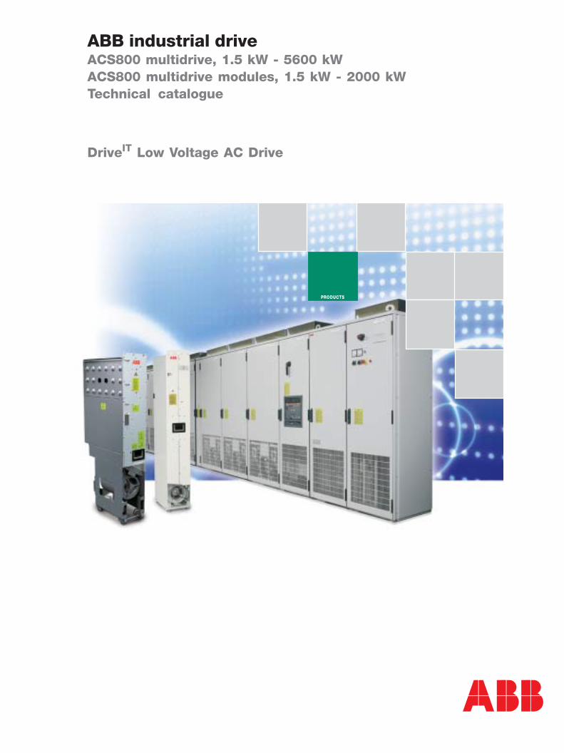
ABB industrial driveACS800 multidrive, 1.5 kW - 5600 kWACS800 multidrive modules, 1.5 kW - 2000 kWTechnical catalogue
DriveIT Low Voltage AC Drive
PRODUCTS
2 3AFE 68248531 REV A EN 31.3.2004
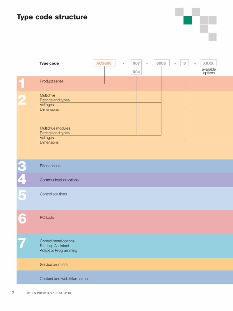
Type code structure
12
345
6
7
Product series
MultidriveRatings and typesVoltagesDimensions
Multidrive modulesRatings and typesVoltagesDimensions
Filter options
Communication options
Control solutions
PC tools
Control panel optionsStart-up AssistantAdaptive Programming
Service products
Contact and web information
availableoptions
Type code ACS800 - X07 - 0003 - 3 + XXXX
X04
33AFE 68248531 REV A EN 31.3.2004
Contents
ABB industrial drive ACS800 multidrive, ACS800 multidrive modules
ABB industrial drive ....................................................... 4Technical specification ................................................... 6
Multidrive main features ................................................. 7Drive and supply unit 400 V ...................................... 8 - 9Drive and supply unit 500 V .................................. 10 - 11Drive and supply unit 690 V .................................. 12 - 13
Braking sections ......................................................... 14
Multidrive modules main features ................................. 15Drive and supply module 400 V............................. 16 - 17Drive and supply module 500 V............................. 18 - 19Drive and supply module 690 V............................. 20 - 21
Braking sections ......................................................... 22
Output filters ............................................................... 25
Control I/O connections............................................... 26
Fieldbus control ........................................................... 27Control solutions .................................................. 28 - 29Remote monitoring tool ............................................... 30
Adaptive Programming ................................................ 31Dimensioning .............................................................. 32Start-up, maintenance and integration .................. 33 - 34
Control panel .............................................................. 35Start-up Assistant ....................................................... 36Adaptive Programming ................................................ 36
.................................................................................. 37
.................................................................................. 38
12
345
6
7
4 3AFE 68248531 REV A EN 31.3.2004
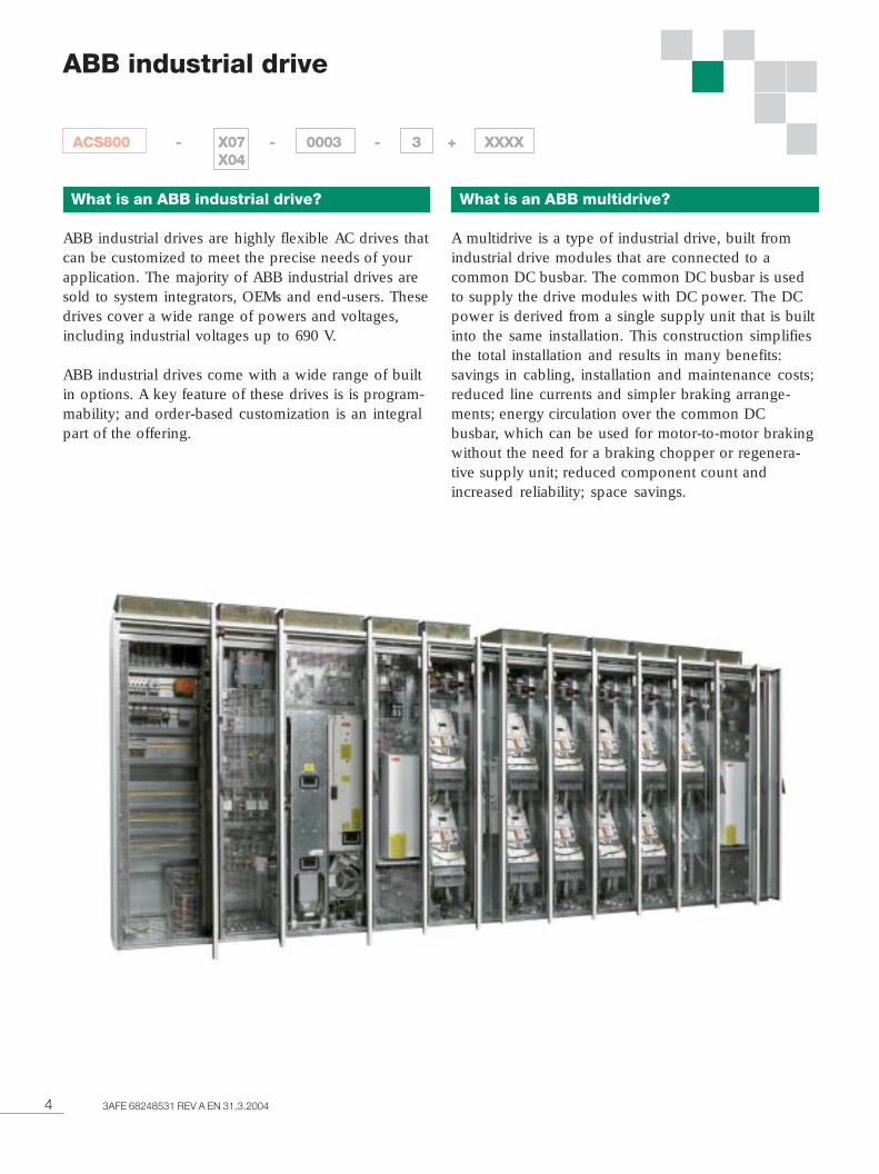
ABB industrial drive
ACS800 - X07 - 0003 - 3 + XXXXX04
What is an ABB industrial drive?
ABB industrial drives are highly flexible AC drives thatcan be customized to meet the precise needs of yourapplication. The majority of ABB industrial drives aresold to system integrators, OEMs and end-users. Thesedrives cover a wide range of powers and voltages,including industrial voltages up to 690 V.
ABB industrial drives come with a wide range of builtin options. A key feature of these drives is is program-mability; and order-based customization is an integralpart of the offering.
What is an ABB multidrive?
A multidrive is a type of industrial drive, built fromindustrial drive modules that are connected to acommon DC busbar. The common DC busbar is usedto supply the drive modules with DC power. The DCpower is derived from a single supply unit that is builtinto the same installation. This construction simplifiesthe total installation and results in many benefits:savings in cabling, installation and maintenance costs;reduced line currents and simpler braking arrange-ments; energy circulation over the common DCbusbar, which can be used for motor-to-motor brakingwithout the need for a braking chopper or regenera-tive supply unit; reduced component count andincreased reliability; space savings.
53AFE 68248531 REV A EN 31.3.2004
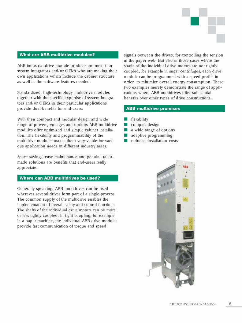
What are ABB multidrive modules?
ABB industrial drive module products are meant forsystem integrators and/or OEMs who are making theirown applications which include the cabinet structureas well as the software features needed.
Standardized, high-technology multidrive modulestogether with the specific expertise of system integra-tors and/or OEMs in their particular applicationsprovide dual benefits for end-users.
With their compact and modular design and widerange of powers, voltages and options ABB multidrivemodules offer optimized and simple cabinet installa-tion. The flexibility and programmability of themultidrive modules makes them very viable for vari-ous application needs in different industry areas.
Space savings, easy maintenance and genuine tailor-made solutions are benefits that end-users reallyappreciate.
Where can ABB multidrives be used?
Generally speaking, ABB multidrives can be usedwherever several drives form part of a single process.The common supply of the multidrive enables theimplementation of overall safety and control functions.The shafts of the individual drive motors can be moreor less tightly coupled. In tight coupling, for examplein a paper machine, the individual ABB drive modulesprovide fast communication of torque and speed
signals between the drives, for controlling the tensionin the paper web. But also in those cases where theshafts of the individual drive motors are not tightlycoupled, for example in sugar centrifuges, each drivemodule can be programmed with a speed profile inorder to minimize overall energy consumption. Thesetwo examples merely demonstrate the range of appli-cations where ABB multidrives offer substantialbenefits over other types of drive constructions.
ABB multidrive promises
■ flexibility■ compact design■ a wide range of options■ adaptive programming■ reduced installation costs
6 3AFE 68248531 REV A EN 31.3.2004
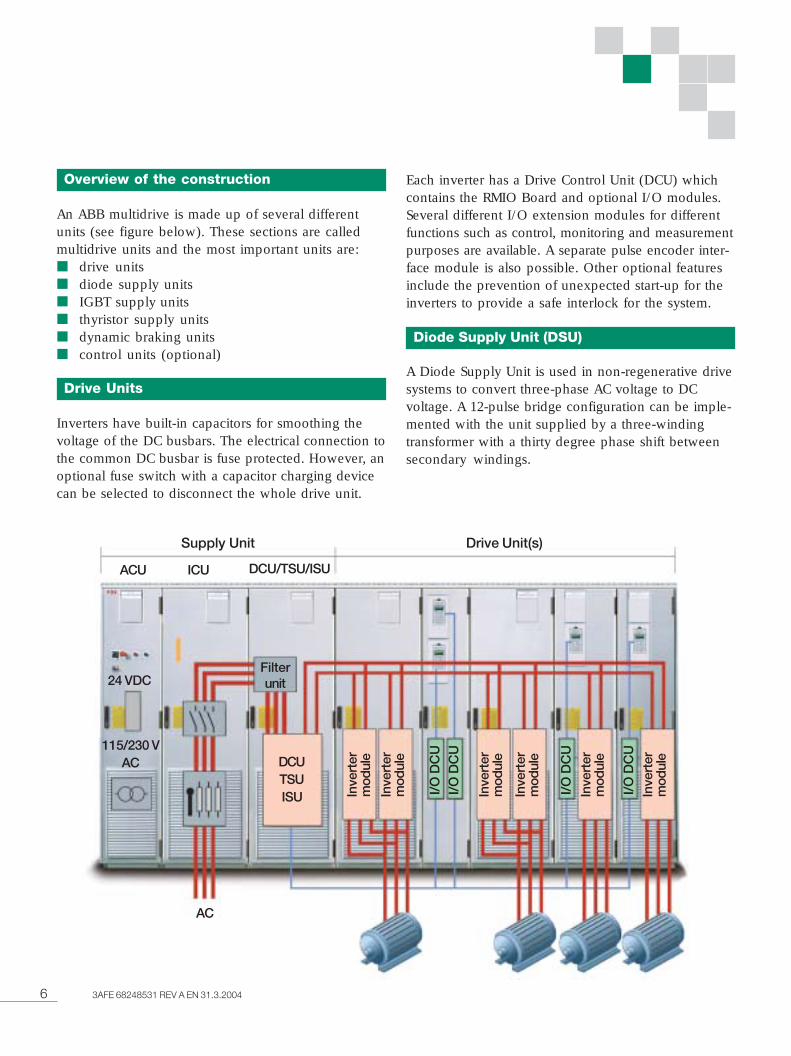
Overview of the construction
An ABB multidrive is made up of several differentunits (see figure below). These sections are calledmultidrive units and the most important units are:■ drive units■ diode supply units■ IGBT supply units■ thyristor supply units■ dynamic braking units■ control units (optional)
Drive Units
Inverters have built-in capacitors for smoothing thevoltage of the DC busbars. The electrical connection tothe common DC busbar is fuse protected. However, anoptional fuse switch with a capacitor charging devicecan be selected to disconnect the whole drive unit.
Each inverter has a Drive Control Unit (DCU) whichcontains the RMIO Board and optional I/O modules.Several different I/O extension modules for differentfunctions such as control, monitoring and measurementpurposes are available. A separate pulse encoder inter-face module is also possible. Other optional featuresinclude the prevention of unexpected start-up for theinverters to provide a safe interlock for the system.
Diode Supply Unit (DSU)
A Diode Supply Unit is used in non-regenerative drivesystems to convert three-phase AC voltage to DCvoltage. A 12-pulse bridge configuration can be imple-mented with the unit supplied by a three-windingtransformer with a thirty degree phase shift betweensecondary windings.
Supply Unit Drive Unit(s)
ACU ICU DCU/TSU/ISU
Filterunit
DCUTSUISU
24 VDC
115/230 VAC
AC
Inve
rter
mod
ule
Inve
rter
mod
ule
Inve
rter
mod
ule
Inve
rter
mod
ule
Inve
rter
mod
ule
Inve
rter
mod
ule
I/O
DC
U
I/O
DC
U
I/O
DC
UI/
O D
CU
73AFE 68248531 REV A EN 31.3.2004
IGBT Supply Unit (ISU)
An IGBT Supply Unit is used in regenerative drivesystems to convert three-phase AC voltage to DCvoltage. In power control it gives the same firm butgentle performance as DTC gives in motor control.
The main circuit consists of a main switch, a filter anda converter. The converter is hardware compatible withdrive units. In the passive mode the converter operatesas the rectifier. In the active mode the IGBTs are con-trolled to keep the DC voltage constant and the linecurrent sinusoidal. The control also provides a nearunity power factor. The control performance is excel-lent due to the ultra-fast control technology, the sameas in DTC.
A fully regenerative IGBT Supply Unit with powerfactor 1 requires no power compensation. The unitcan also boost motor voltage when line voltage is low.Harmonic content remains extremely low due to DTCcontrol and LCL filtering.
Thyristor Supply Unit (TSU)
A thyristor supply unit is used in regenerative drivesystems to convert three-phase AC voltage to DCvoltage. The Thyristor Supply Unit contains two6-pulse thyristor bridges in antiparallel connection. Ithas the ability to regenerate back to the mains, provid-ing considerable energy savings with applicationshaving excessive braking powers. A 12-pulse bridge
configuration can be implemented with two thyristorsupply units supplied by a three-winding transformer.This configuration reduces harmonics in the supplynetwork.
Dynamic Braking Unit (DBU)
In resistor braking whenever the voltage in the inter-mediate circuit of a frequency converter exceeds acertain limit, a braking chopper connects the circuit toa braking resistor.
Standard braking resistors are separately available intheir own cabinets. Non-standard resistors can be usedproviding that the specified resistance value is notdecreased and that the heat dissipation capacity of theresistor is sufficient for the drive application.
AC800M Control Unit (Optional)
The Multidrive concept also includes the control unitfor the AC800M and S800 I/O. The control unit isequipped with communication interfaces, powersupplies and the front-devices necessary for theautomation equipment.
8 3AFE 68248531 REV A EN 31.3.2004
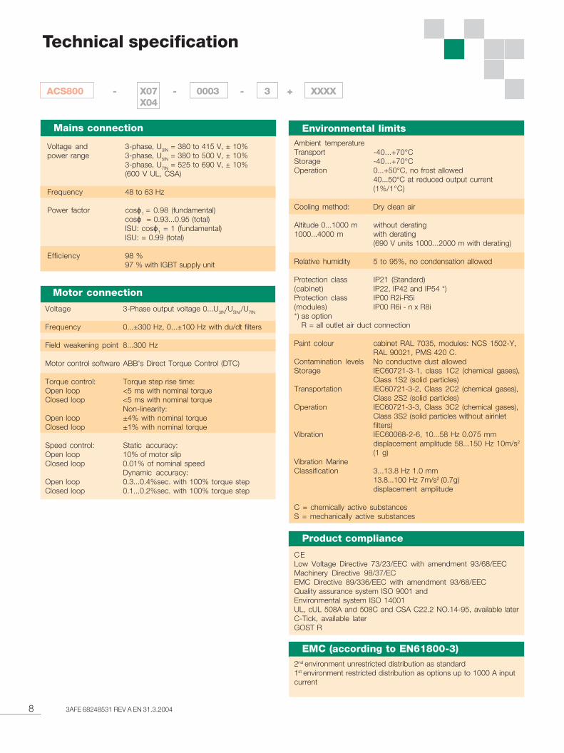
Voltage 3-Phase output voltage 0...U3IN/U5IN//U7IN
Frequency 0...±300 Hz, 0...±100 Hz with du/dt filters
Field weakening point 8...300 Hz
Motor control software ABB’s Direct Torque Control (DTC)
Torque control: Torque step rise time:Open loop <5 ms with nominal torqueClosed loop <5 ms with nominal torque
Non-linearity:Open loop ±4% with nominal torqueClosed loop ±1% with nominal torque
Speed control: Static accuracy:Open loop 10% of motor slipClosed loop 0.01% of nominal speed
Dynamic accuracy:Open loop 0.3...0.4%sec. with 100% torque stepClosed loop 0.1...0.2%sec. with 100% torque step
Technical specification
CELow Voltage Directive 73/23/EEC with amendment 93/68/EECMachinery Directive 98/37/ECEMC Directive 89/336/EEC with amendment 93/68/EECQuality assurance system ISO 9001 andEnvironmental system ISO 14001UL, cUL 508A and 508C and CSA C22.2 NO.14-95, available laterC-Tick, available laterGOST R
2nd environment unrestricted distribution as standard1st environment restricted distribution as options up to 1000 A inputcurrent
Motor connection
Product compliance
EMC (according to EN61800-3)
Mains connection
Voltage and 3-phase, U3IN = 380 to 415 V, ± 10%power range 3-phase, U5IN = 380 to 500 V, ± 10%
3-phase, U7IN = 525 to 690 V, ± 10%(600 V UL, CSA)
Frequency 48 to 63 Hz
Power factor cosϕ1 = 0.98 (fundamental)cosϕ = 0.93...0.95 (total)ISU: cosϕ1 = 1 (fundamental)ISU: = 0.99 (total)
Efficiency 98 %97 % with IGBT supply unit
Environmental limitsAmbient temperatureTransport -40...+70°CStorage -40...+70°COperation 0...+50°C, no frost allowed
40...50°C at reduced output current(1%/1°C)
Cooling method: Dry clean air
Altitude 0...1000 m without derating1000...4000 m with derating
(690 V units 1000...2000 m with derating)
Relative humidity 5 to 95%, no condensation allowed
Protection class IP21 (Standard)(cabinet) IP22, IP42 and IP54 *)Protection class IP00 R2i-R5i(modules) IP00 R6i - n x R8i*) as option
R = all outlet air duct connection
Paint colour cabinet RAL 7035, modules: NCS 1502-Y,RAL 90021, PMS 420 C.
Contamination levels No conductive dust allowedStorage IEC60721-3-1, class 1C2 (chemical gases),
Class 1S2 (solid particles)Transportation IEC60721-3-2, Class 2C2 (chemical gases),
Class 2S2 (solid particles)Operation IEC60721-3-3, Class 3C2 (chemical gases),
Class 3S2 (solid particles without airinletfilters)
Vibration IEC60068-2-6, 10...58 Hz 0.075 mmdisplacement amplitude 58...150 Hz 10m/s2
(1 g)Vibration MarineClassification 3...13.8 Hz 1.0 mm
13.8...100 Hz 7m/s2 (0.7g)displacement amplitude
C = chemically active substancesS = mechanically active substances
ACS800 - X07 - 0003 - 3 + XXXXX04
93AFE 68248531 REV A EN 31.3.2004
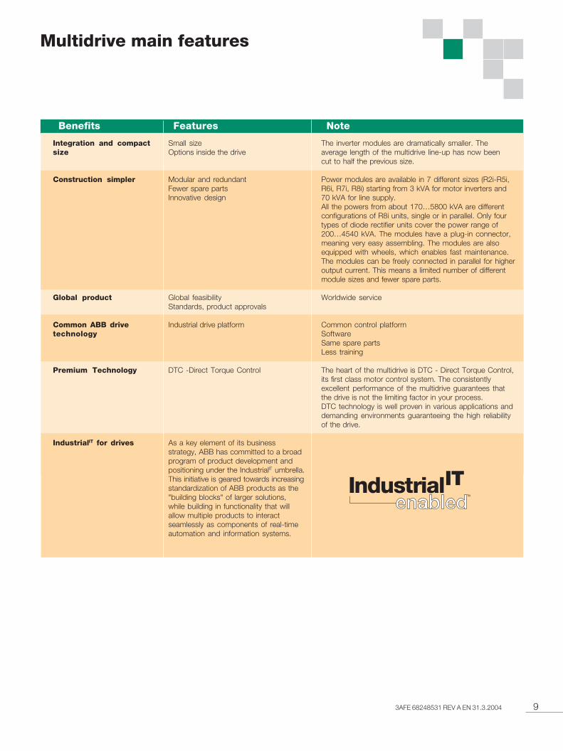
Multidrive main features
NoteBenefits Features
Small sizeOptions inside the drive
Modular and redundantFewer spare partsInnovative design
Global feasibilityStandards, product approvals
Industrial drive platform
DTC -Direct Torque Control
As a key element of its businessstrategy, ABB has committed to a broadprogram of product development andpositioning under the IndustrialIT umbrella.This initiative is geared towards increasingstandardization of ABB products as the"building blocks" of larger solutions,while building in functionality that willallow multiple products to interactseamlessly as components of real-timeautomation and information systems.
The inverter modules are dramatically smaller. Theaverage length of the multidrive line-up has now beencut to half the previous size.
Power modules are available in 7 different sizes (R2i-R5i,R6i, R7i, R8i) starting from 3 kVA for motor inverters and70 kVA for line supply.All the powers from about 170…5800 kVA are differentconfigurations of R8i units, single or in parallel. Only fourtypes of diode rectifier units cover the power range of200…4540 kVA. The modules have a plug-in connector,meaning very easy assembling. The modules are alsoequipped with wheels, which enables fast maintenance.The modules can be freely connected in parallel for higheroutput current. This means a limited number of differentmodule sizes and fewer spare parts.
Worldwide service
Common control platformSoftwareSame spare partsLess training
The heart of the multidrive is DTC - Direct Torque Control,its first class motor control system. The consistentlyexcellent performance of the multidrive guarantees thatthe drive is not the limiting factor in your process.DTC technology is well proven in various applications anddemanding environments guaranteeing the high reliabilityof the drive.
Integration and compactsize
Construction simpler
Global product
Common ABB drivetechnology
Premium Technology
IndustrialIT for drives
10 3AFE 68248531 REV A EN 31.3.2004
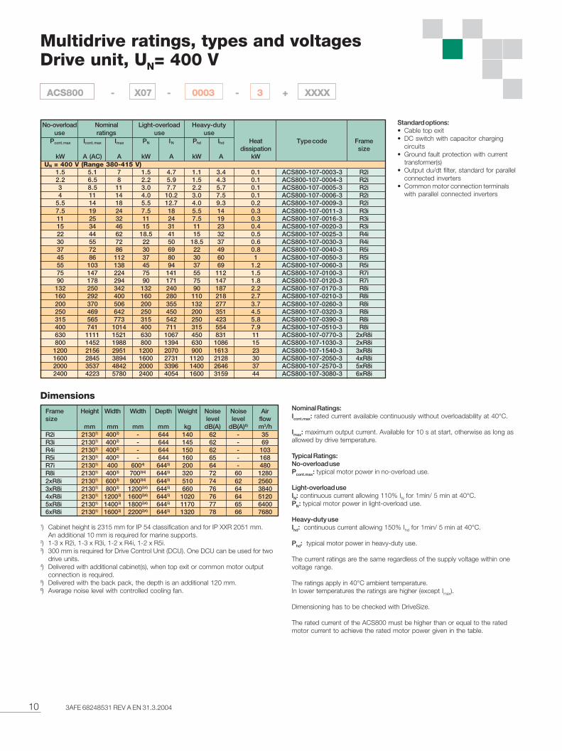
Multidrive ratings, types and voltagesDrive unit, UN= 400 V
Pcont. max Icont. max Imax PN IN Phd Ihd Heat Type code Framedissipation size
kW A (AC) A kW A kW A kWUN = 400 V (Range 380-415 V)
1.5 5.1 7 1.5 4.7 1.1 3.4 0.1 ACS800-107-0003-3 R2i2.2 6.5 8 2.2 5.9 1.5 4.3 0.1 ACS800-107-0004-3 R2i3 8.5 11 3.0 7.7 2.2 5.7 0.1 ACS800-107-0005-3 R2i4 11 14 4.0 10.2 3.0 7.5 0.1 ACS800-107-0006-3 R2i
5.5 14 18 5.5 12.7 4.0 9.3 0.2 ACS800-107-0009-3 R2i7.5 19 24 7.5 18 5.5 14 0.3 ACS800-107-0011-3 R3i11 25 32 11 24 7.5 19 0.3 ACS800-107-0016-3 R3i15 34 46 15 31 11 23 0.4 ACS800-107-0020-3 R3i22 44 62 18.5 41 15 32 0.5 ACS800-107-0025-3 R4i30 55 72 22 50 18.5 37 0.6 ACS800-107-0030-3 R4i37 72 86 30 69 22 49 0.8 ACS800-107-0040-3 R5i45 86 112 37 80 30 60 1 ACS800-107-0050-3 R5i55 103 138 45 94 37 69 1.2 ACS800-107-0060-3 R5i75 147 224 75 141 55 112 1.5 ACS800-107-0100-3 R7i90 178 294 90 171 75 147 1.8 ACS800-107-0120-3 R7i
132 250 342 132 240 90 187 2.2 ACS800-107-0170-3 R8i160 292 400 160 280 110 218 2.7 ACS800-107-0210-3 R8i200 370 506 200 355 132 277 3.7 ACS800-107-0260-3 R8i250 469 642 250 450 200 351 4.5 ACS800-107-0320-3 R8i315 565 773 315 542 250 423 5.8 ACS800-107-0390-3 R8i400 741 1014 400 711 315 554 7.9 ACS800-107-0510-3 R8i630 1111 1521 630 1067 450 831 11 ACS800-107-0770-3 2xR8i800 1452 1988 800 1394 630 1086 15 ACS800-107-1030-3 2xR8i
1200 2156 2951 1200 2070 900 1613 23 ACS800-107-1540-3 3xR8i1600 2845 3894 1600 2731 1120 2128 30 ACS800-107-2050-3 4xR8i2000 3537 4842 2000 3396 1400 2646 37 ACS800-107-2570-3 5xR8i2400 4223 5780 2400 4054 1600 3159 44 ACS800-107-3080-3 6xR8i
Frame Height Width Width Depth Weight Noise Noise Airsize level level flow
mm mm mm mm kg dB(A) dB(A)6) m3/hR2i 21301) 4002) - 644 140 62 - 35R3i 21301) 4002) - 644 145 62 - 69R4i 21301) 4002) - 644 150 62 - 103R5i 21301) 4002) - 644 160 65 - 168R7i 21301) 400 6004) 6445) 200 64 - 480R8i 21301) 4003) 7003)4) 6445) 320 72 60 12802xR8i 21301) 6003) 9003)4) 6445) 510 74 62 25603xR8i 21301) 8003) 12003)4) 6445) 660 76 64 38404xR8i 21301) 12003) 16003)4) 6445) 1020 76 64 51205xR8i 21301) 14003) 18003)4) 6445) 1170 77 65 64006xR8i 21301) 16003) 22003)4) 6445) 1320 78 66 7680
Standard options:• Cable top exit• DC switch with capacitor charging
circuits• Ground fault protection with current
transformer(s)• Output du/dt filter, standard for parallel
connected inverters• Common motor connection terminals
with parallel connected inverters
Nominal Ratings:Icont.max: rated current available continuously without overloadability at 40°C.
Imax: maximum output current. Available for 10 s at start, otherwise as long asallowed by drive temperature.
Typical Ratings:No-overload usePcont.max: typical motor power in no-overload use.
Light-overload useIN: continuous current allowing 110% IN for 1min/ 5 min at 40°C.PN: typical motor power in light-overload use.
Heavy-duty useIhd: continuous current allowing 150% Ihd for 1min/ 5 min at 40°C.
Phd: typical motor power in heavy-duty use.
The current ratings are the same regardless of the supply voltage within onevoltage range.
The ratings apply in 40°C ambient temperature.In lower temperatures the ratings are higher (except Imax).
Dimensioning has to be checked with DriveSize.
The rated current of the ACS800 must be higher than or equal to the ratedmotor current to achieve the rated motor power given in the table.
Dimensions
1) Cabinet height is 2315 mm for IP 54 classification and for IP XXR 2051 mm.An additional 10 mm is required for marine supports.
2) 1-3 x R2i, 1-3 x R3i, 1-2 x R4i, 1-2 x R5i.3) 300 mm is required for Drive Control Unit (DCU). One DCU can be used for two
drive units.4) Delivered with additional cabinet(s), when top exit or common motor output
connection is required.5) Delivered with the back pack, the depth is an additional 120 mm.6) Average noise level with controlled cooling fan.
Nominalratings
No-overloaduse
Light-overloaduse
Heavy-dutyuse
ACS800 - X07 - 0003 - 3 + XXXX
113AFE 68248531 REV A EN 31.3.2004
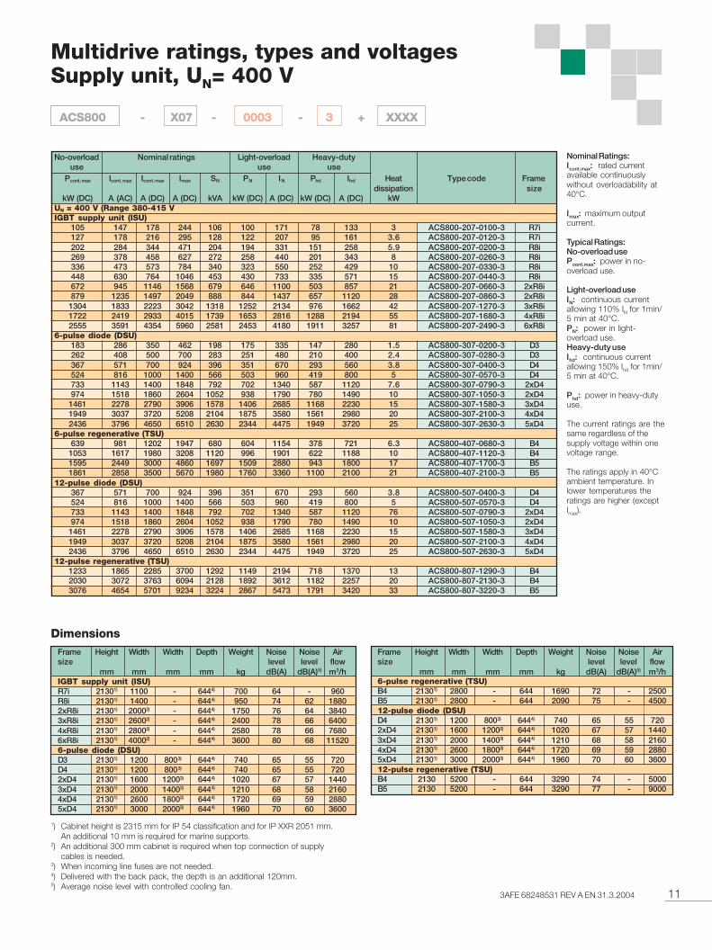
Multidrive ratings, types and voltagesSupply unit, UN= 400 V
Pcont. max Icont. max Icont. max Imax SN PN IN Phd Ihd Heat Type code Framedissipation size
kW (DC) A (AC) A (DC) A (DC) kVA kW (DC) A (DC) kW (DC) A (DC) kWUN = 400 V (Range 380-415 VIGBT supply unit (ISU)
105 147 178 244 106 100 171 78 133 3 ACS800-207-0100-3 R7i127 178 216 295 128 122 207 95 161 3.6 ACS800-207-0120-3 R7i202 284 344 471 204 194 331 151 258 5.9 ACS800-207-0200-3 R8i269 378 458 627 272 258 440 201 343 8 ACS800-207-0260-3 R8i336 473 573 784 340 323 550 252 429 10 ACS800-207-0330-3 R8i448 630 764 1046 453 430 733 335 571 15 ACS800-207-0440-3 R8i672 945 1146 1568 679 646 1100 503 857 21 ACS800-207-0660-3 2xR8i879 1235 1497 2049 888 844 1437 657 1120 28 ACS800-207-0860-3 2xR8i
1304 1833 2223 3042 1318 1252 2134 976 1662 42 ACS800-207-1270-3 3xR8i1722 2419 2933 4015 1739 1653 2816 1288 2194 55 ACS800-207-1680-3 4xR8i2555 3591 4354 5960 2581 2453 4180 1911 3257 81 ACS800-207-2490-3 6xR8i
6-pulse diode (DSU)183 286 350 462 198 175 335 147 280 1.5 ACS800-307-0200-3 D3262 408 500 700 283 251 480 210 400 2.4 ACS800-307-0280-3 D3367 571 700 924 396 351 670 293 560 3.8 ACS800-307-0400-3 D4524 816 1000 1400 566 503 960 419 800 5 ACS800-307-0570-3 D4733 1143 1400 1848 792 702 1340 587 1120 7.6 ACS800-307-0790-3 2xD4974 1518 1860 2604 1052 938 1790 780 1490 10 ACS800-307-1050-3 2xD4
1461 2278 2790 3906 1578 1406 2685 1168 2230 15 ACS800-307-1580-3 3xD41949 3037 3720 5208 2104 1875 3580 1561 2980 20 ACS800-307-2100-3 4xD42436 3796 4650 6510 2630 2344 4475 1949 3720 25 ACS800-307-2630-3 5xD4
6-pulse regenerative (TSU)639 981 1202 1947 680 604 1154 378 721 6.3 ACS800-407-0680-3 B4
1053 1617 1980 3208 1120 996 1901 622 1188 10 ACS800-407-1120-3 B41595 2449 3000 4860 1697 1509 2880 943 1800 17 ACS800-407-1700-3 B51861 2858 3500 5670 1980 1760 3360 1100 2100 21 ACS800-407-2100-3 B5
12-pulse diode (DSU)367 571 700 924 396 351 670 293 560 3.8 ACS800-507-0400-3 D4524 816 1000 1400 566 503 960 419 800 5 ACS800-507-0570-3 D4733 1143 1400 1848 792 702 1340 587 1120 76 ACS800-507-0790-3 2xD4974 1518 1860 2604 1052 938 1790 780 1490 10 ACS800-507-1050-3 2xD4
1461 2278 2790 3906 1578 1406 2685 1168 2230 15 ACS800-507-1580-3 3xD41949 3037 3720 5208 2104 1875 3580 1561 2980 20 ACS800-507-2100-3 4xD42436 3796 4650 6510 2630 2344 4475 1949 3720 25 ACS800-507-2630-3 5xD4
12-pulse regenerative (TSU)1233 1865 2285 3700 1292 1149 2194 718 1370 13 ACS800-807-1290-3 B42030 3072 3763 6094 2128 1892 3612 1182 2257 20 ACS800-807-2130-3 B43076 4654 5701 9234 3224 2867 5473 1791 3420 33 ACS800-807-3220-3 B5
Dimensions
Nominal Ratings:Icont.max: rated currentavailable continuouslywithout overloadability at40°C.
Imax: maximum outputcurrent.
Typical Ratings:No-overload usePcont.max: power in no-overload use.
Light-overload useIN: continuous currentallowing 110% IN for 1min/5 min at 40°C.PN: power in light-overload use.Heavy-duty useIhd: continuous currentallowing 150% Ihd for 1min/5 min at 40°C.
Phd: power in heavy-dutyuse.
The current ratings are thesame regardless of thesupply voltage within onevoltage range.
The ratings apply in 40°Cambient temperature. Inlower temperatures theratings are higher (exceptImax).
Frame Height Width Width Depth Weight Noise Noise Airsize level level flow
mm mm mm mm kg dB(A) dB(A)5) m3/hIGBT supply unit (ISU)R7i 21301) 1100 - 6444) 700 64 - 960R8i 21301) 1400 - 6444) 950 74 62 18802xR8i 21301) 20002) - 6444) 1750 76 64 38403xR8i 21301) 26002) - 6444) 2400 78 66 64004xR8i 21301) 28002) - 6444) 2580 78 66 76806xR8i 21301) 40002) - 6444) 3600 80 68 115206-pulse diode (DSU)D3 21301) 1200 8003) 6444) 740 65 55 720D4 21301) 1200 8003) 6444) 740 65 55 7202xD4 21301) 1600 12003) 6444) 1020 67 57 14403xD4 21301) 2000 14003) 6444) 1210 68 58 21604xD4 21301) 2600 18003) 6444) 1720 69 59 28805xD4 21301) 3000 20003) 6444) 1960 70 60 3600
Frame Height Width Width Depth Weight Noise Noise Airsize level level flow
mm mm mm mm kg dB(A) dB(A)5) m3/h6-pulse regenerative (TSU)B4 21301) 2800 - 644 1690 72 - 2500B5 21301) 2800 - 644 2090 75 - 450012-pulse diode (DSU)D4 21301) 1200 8003) 6444) 740 65 55 7202xD4 21301) 1600 12003) 6444) 1020 67 57 14403xD4 21301) 2000 14003) 6444) 1210 68 58 21604xD4 21301) 2600 18003) 6444) 1720 69 59 28805xD4 21301) 3000 20003) 6444) 1960 70 60 360012-pulse regenerative (TSU)B4 2130 5200 - 644 3290 74 - 5000B5 2130 5200 - 644 3290 77 - 9000
Nominal ratingsNo-overloaduse
Light-overloaduse
Heavy-dutyuse
1) Cabinet height is 2315 mm for IP 54 classification and for IP XXR 2051 mm.An additional 10 mm is required for marine supports.
2) An additional 300 mm cabinet is required when top connection of supplycables is needed.
3) When incoming line fuses are not needed.4) Delivered with the back pack, the depth is an additional 120mm.5) Average noise level with controlled cooling fan.
ACS800 - X07 - 0003 - 3 + XXXX
12 3AFE 68248531 REV A EN 31.3.2004
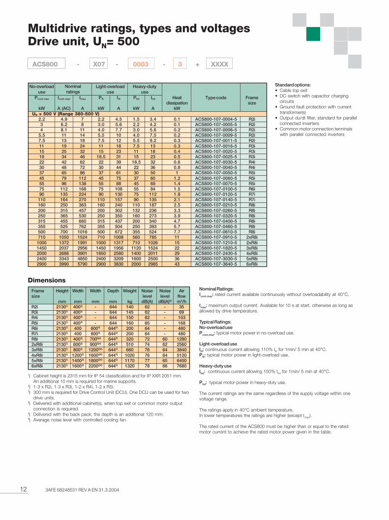
Multidrive ratings, types and voltagesDrive unit, UN= 500
Standard options:• Cable top exit• DC switch with capacitor charging
circuits• Ground fault protection with current
transformer(s)• Output du/dt filter, standard for parallel
connected inverters• Common motor connection terminals
with parallel connected inverters
Nominal Ratings:Icont.max: rated current available continuously without overloadability at 40°C.
Imax: maximum output current. Available for 10 s at start, otherwise as long asallowed by drive temperature.
Typical Ratings:No-overload usePcont.max: typical motor power in no-overload use.
Light-overload useIN: continuous current allowing 110% IN for 1min/ 5 min at 40°C.PN: typical motor power in light-overload use.
Heavy-duty useIhd: continuous current allowing 150% Ihd for 1min/ 5 min at 40°C.
Phd: typical motor power in heavy-duty use.
The current ratings are the same regardless of the supply voltage within onevoltage range.
The ratings apply in 40°C ambient temperature.In lower temperatures the ratings are higher (except Imax).
The rated current of the ACS800 must be higher than or equal to the ratedmotor current to achieve the rated motor power given in the table.
Pcont. max Icont. max Imax PN IN Phd Ihd Heat Type code Framedissipation size
kW A (AC) A kW A kW A kW UN = 500 V (Range 380-500 V)
2.2 4.9 7 2.2 4.5 1.5 3.4 0.1 ACS800-107-0004-5 R2i3 6.2 8 3.0 5.6 2.2 4.2 0.1 ACS800-107-0005-5 R2i4 8.1 11 4.0 7.7 3.0 5.6 0.2 ACS800-107-0006-5 R2i
5.5 11 14 5.5 10 4.0 7.5 0.2 ACS800-107-0009-5 R2i7.5 13 18 7.5 12 5.5 9.2 0.3 ACS800-107-0011-5 R2i11 19 24 11 18 7.5 13 0.3 ACS800-107-0016-5 R3i15 25 32 15 23 11 18 0.4 ACS800-107-0020-5 R3i19 34 46 18.5 31 15 23 0.5 ACS800-107-0025-5 R3i22 42 62 22 39 18.5 32 0.6 ACS800-107-0030-5 R4i30 48 72 30 44 22 36 0.8 ACS800-107-0040-5 R4i37 65 86 37 61 30 50 1 ACS800-107-0050-5 R5i45 79 112 45 75 37 60 1.2 ACS800-107-0060-5 R5i55 96 138 55 88 45 69 1.4 ACS800-107-0070-5 R5i75 112 168 75 108 55 84 1.5 ACS800-107-0100-5 R6i90 135 224 90 130 75 112 1.8 ACS800-107-0120-5 R7i
110 164 270 110 157 90 135 2.1 ACS800-107-0140-5 R7i160 250 363 160 240 110 187 2.5 ACS800-107-0210-5 R8i200 315 457 200 302 132 236 3.3 ACS800-107-0260-5 R8i250 365 530 250 350 160 273 3.9 ACS800-107-0320-5 R8i315 455 660 315 437 200 340 4.7 ACS800-107-0400-5 R8i355 525 762 355 504 250 393 5.7 ACS800-107-0460-5 R8i500 700 1016 500 672 355 524 7.7 ACS800-107-0610-5 R8i710 1050 1524 710 1008 560 785 11 ACS800-107-0910-5 2xR8i
1000 1372 1991 1000 1317 710 1026 15 ACS800-107-1210-5 2xR8i1450 2037 2956 1450 1956 1120 1524 22 ACS800-107-1820-5 3xR8i2000 2688 3901 1850 2580 1400 2011 29 ACS800-107-2430-5 4xR8i2400 3343 4850 2400 3209 1600 2500 36 ACS800-107-3030-5 5xR8i2900 3990 5790 2900 3830 2000 2985 43 ACS800-107-3640-5 6xR8i
Nominalratings
No-overloaduse
Light-overloaduse
Heavy-dutyuse
Dimensions
Frame Height Width Width Depth Weight Noise Noise Airsize level level flow
mm mm mm mm kg dB(A) dB(A)6) m3/hR2i 21301) 4002) - 644 140 62 - 35R3i 21301) 4002) - 644 145 62 - 69R4i 21301) 4002) - 644 150 62 - 103R5i 21301) 4002) - 644 160 65 - 168R6i 21301) 400 6004) 6445) 200 64 - 480R7i 21301) 400 6004) 6445) 200 64 - 480R8i 21301) 4003) 7003)4) 6445) 320 72 60 12802xR8i 21301) 6003) 9003)4) 6445) 510 74 62 25603xR8i 21301) 8003) 12003)4) 6445) 660 76 64 38404xR8i 21301) 12003) 16003)4) 6445) 1020 76 64 51205xR8i 21301) 14003) 18003)4) 6445) 1170 77 65 64006xR8i 21301) 16003) 22003)4) 6445) 1320 78 66 7680
ACS800 - X07 - 0003 - 3 + XXXX
1) Cabinet height is 2315 mm for IP 54 classification and for IP XXR 2051 mm.An additional 10 mm is required for marine supports.
2) 1-3 x R2i, 1-3 x R3i, 1-2 x R4i, 1-2 x R5i.3) 300 mm is required for Drive Control Unit (DCU). One DCU can be used for two
drive units.4) Delivered with additional cabinet(s), when top exit or common motor output
connection is required.5) Delivered with the back pack, the depth is an additional 120 mm.6) Average noise level with controlled cooling fan.
133AFE 68248531 REV A EN 31.3.2004
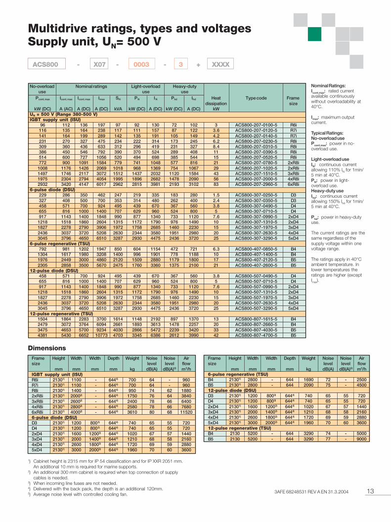
Multidrive ratings, types and voltagesSupply unit, UN= 500 V
Pcont. max Icont. max Icont. max Imax SN PN IN Phd Ihd Heat Type code Framedissipation size
kW (DC) A (AC) A (DC) A (DC) kVA kW (DC) A (DC) kW (DC) A (DC) kWUN = 500 V (Range 380-500 V)IGBT supply unit (ISU)
96 112 136 197 97 92 130 72 102 3 ACS800-207-0100-5 R6i116 135 164 238 117 111 157 87 122 3.6 ACS800-207-0120-5 R7i141 164 199 289 142 135 191 105 149 4.2 ACS800-207-0140-5 R7i231 270 327 475 234 222 314 173 245 6.2 ACS800-207-0230-5 R8i309 360 436 633 312 296 419 231 327 8.4 ACS800-207-0310-5 R8i386 450 546 792 390 370 524 289 408 11 ACS800-207-0390-5 R8i514 600 727 1056 520 494 698 385 544 15 ACS800-207-0520-5 R8i772 900 1091 1584 779 741 1048 577 816 21 ACS800-207-0780-5 2xR8i
1008 1176 1426 2069 1018 968 1369 754 1067 29 ACS800-207-1020-5 2xR8i1497 1746 2117 3072 1512 1437 2032 1120 1584 43 ACS800-207-1510-5 3xR8i1975 2304 2794 4054 1995 1896 2682 1478 2090 56 ACS800-207-2000-5 4xR8i2932 3420 4147 6017 2962 2815 3981 2193 3102 83 ACS800-207-2960-5 6xR8i
6-pulse diode (DSU)229 286 350 462 247 219 335 183 280 1.5 ACS800-307-0250-5 D3327 408 500 700 353 314 480 262 400 2.4 ACS800-307-0350-5 D3458 571 700 924 495 439 670 367 560 3.8 ACS800-307-0490-5 D4655 816 1000 1400 707 629 960 524 800 5 ACS800-307-0710-5 D4917 1143 1400 1848 990 877 1340 733 1120 7.6 ACS800-307-0990-5 2xD4
1218 1518 1860 2604 1315 1172 1790 976 1490 10 ACS800-307-1310-5 2xD41827 2278 2790 3906 1972 1758 2685 1460 2230 15 ACS800-307-1970-5 3xD42436 3037 3720 5208 2630 2344 3580 1951 2980 20 ACS800-307-2630-5 4xD43045 3796 4650 6510 3287 2930 4475 2436 3720 25 ACS800-307-3290-5 5xD4
6-pulse regenerative (TSU)792 981 1202 1947 850 604 1154 472 721 6.3 ACS800-407-0850-5 B4
1304 1617 1980 3208 1400 996 1901 778 1188 10 ACS800-407-1400-5 B41976 2449 3000 4860 2120 1509 2880 1179 1800 17 ACS800-407-2120-5 B52305 2858 3500 5670 2475 1760 3360 1375 2100 21 ACS800-407-2600-5 B5
12-pulse diode (DSU)458 571 700 924 495 439 670 367 560 3.8 ACS800-507-0490-5 D4655 816 1000 1400 707 629 960 524 800 5 ACS800-507-0710-5 D4917 1143 1400 1848 990 877 1340 733 1120 7.6 ACS800-507-0990-5 2xD4
1218 1518 1860 2604 1315 1172 1790 976 1490 10 ACS800-507-1310-5 2xD41827 2278 2790 3906 1972 1758 2685 1460 2230 15 ACS800-507-1970-5 3xD42436 3037 3720 5208 2630 2344 3580 1951 2980 20 ACS800-507-2630-5 4xD43045 3796 4650 6510 3287 2930 4475 2436 3720 25 ACS800-507-3290-5 5xD4
12-pulse regenerative (TSU)1504 1864 2283 3700 1614 1148 2192 897 1370 13 ACS800-807-1615-5 B42479 3072 3764 6094 2661 1893 3613 1478 2257 20 ACS800-807-2660-5 B43475 4653 5700 9234 4030 2866 5472 2239 3420 33 ACS800-807-4030-5 B54381 5430 6652 10773 4703 3345 6386 2612 3990 42 ACS800-807-4700-5 B5
Nominal ratingsNo-overloaduse
Light-overloaduse
Heavy-dutyuse
DimensionsFrame Height Width Width Depth Weight Noise Noise Airsize level level flow
mm mm mm mm kg dB(A) dB(A)5) m3/h
Frame Height Width Width Depth Weight Noise Noise Airsize level level flow
mm mm mm mm kg dB(A) dB(A)5) m3/hIGBT supply unit (ISU)R6i 21301) 1100 - 6444) 700 64 - 960R7i 21301) 1100 - 6444) 700 64 - 960R8i 21301) 1400 - 6444) 950 74 62 18802xR8i 21301) 20002) - 6444) 1750 76 64 38403xR8i 21301) 26002) - 6444) 2400 78 66 64004xR8i 21301) 28002) - 6444) 2580 78 66 76806xR8i 21301) 40002) - 6444) 3610 80 68 115206-pulse diode (DSU)D3 21301) 1200 8003) 6444) 740 65 55 720D4 21301) 1200 8003) 6444) 740 65 55 7202xD4 21301) 1600 12003) 6444) 1020 67 57 14403xD4 21301) 2000 14003) 6444) 1210 68 58 21604xD4 21301) 2600 18003) 6444) 1720 69 59 28805xD4 21301) 3000 20003) 6444) 1960 70 60 3600
6-pulse regenerative (TSU)B4 21301) 2800 - 644 1690 72 - 2500B5 21301) 2800 - 644 2090 75 - 450012-pulse diode (DSU)D3 21301) 1200 8003) 6444) 740 65 55 720D4 21301) 1200 8003) 6444) 740 65 55 7202xD4 21301) 1600 12003) 6444) 1020 67 57 14403xD4 21301) 2000 14003) 6444) 1210 68 58 21604xD4 21301) 2600 18003) 6444) 1720 69 59 28805xD4 21301) 3000 20003) 6444) 1960 70 60 360012-pulse regenerative (TSU)B4 2130 5200 - 644 3290 74 - 5000B5 2130 5200 - 644 3290 77 - 9000
Nominal Ratings:Icont.max: rated currentavailable continuouslywithout overloadability at40°C.
Imax: maximum outputcurrent.
Typical Ratings:No-overload usePcont.max: power in no-overload use.
Light-overload useIN: continuous currentallowing 110% IN for 1min/5 min at 40°C.PN: power in light-overload use.Heavy-duty useIhd: continuous currentallowing 150% Ihd for 1min/5 min at 40°C.
Phd: power in heavy-dutyuse.
The current ratings are thesame regardless of thesupply voltage within onevoltage range.
The ratings apply in 40°Cambient temperature. Inlower temperatures theratings are higher (exceptImax).
ACS800 - X07 - 0003 - 3 + XXXX
1) Cabinet height is 2315 mm for IP 54 classification and for IP XXR 2051 mm.An additional 10 mm is required for marine supports.
2) An additional 300 mm cabinet is required when top connection of supplycables is needed.
3) When incoming line fuses are not needed.4) Delivered with the back pack, the depth is an additional 120mm.5) Average noise level with controlled cooling fan.
14 3AFE 68248531 REV A EN 31.3.2004
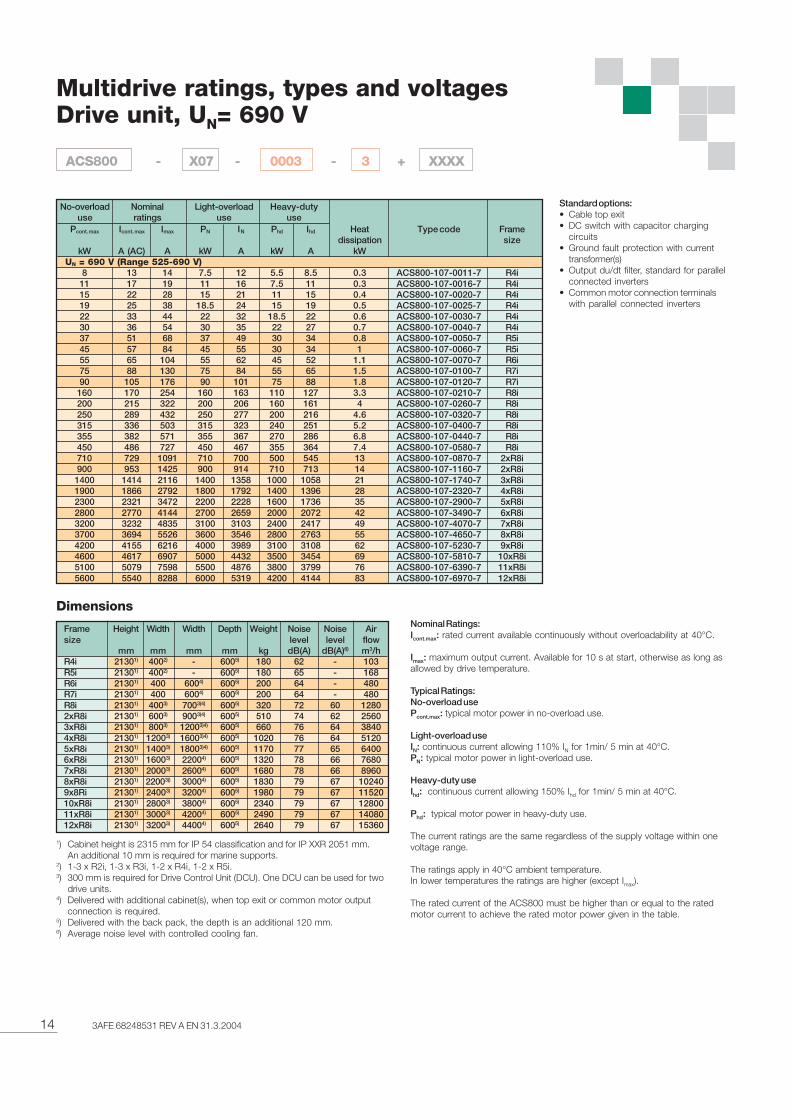
Multidrive ratings, types and voltagesDrive unit, UN= 690 V
Standard options:• Cable top exit• DC switch with capacitor charging
circuits• Ground fault protection with current
transformer(s)• Output du/dt filter, standard for parallel
connected inverters• Common motor connection terminals
with parallel connected inverters
Nominal Ratings:Icont.max: rated current available continuously without overloadability at 40°C.
Imax: maximum output current. Available for 10 s at start, otherwise as long asallowed by drive temperature.
Typical Ratings:No-overload usePcont.max: typical motor power in no-overload use.
Light-overload useIN: continuous current allowing 110% IN for 1min/ 5 min at 40°C.PN: typical motor power in light-overload use.
Heavy-duty useIhd: continuous current allowing 150% Ihd for 1min/ 5 min at 40°C.
Phd: typical motor power in heavy-duty use.
The current ratings are the same regardless of the supply voltage within onevoltage range.
The ratings apply in 40°C ambient temperature.In lower temperatures the ratings are higher (except Imax).
The rated current of the ACS800 must be higher than or equal to the ratedmotor current to achieve the rated motor power given in the table.
Pcont. max Icont. max Imax PN IN Phd Ihd Heat Type code Framedissipation size
kW A (AC) A kW A kW A kW UN = 690 V (Range 525-690 V)
8 13 14 7.5 12 5.5 8.5 0.3 ACS800-107-0011-7 R4i11 17 19 11 16 7.5 11 0.3 ACS800-107-0016-7 R4i15 22 28 15 21 11 15 0.4 ACS800-107-0020-7 R4i19 25 38 18.5 24 15 19 0.5 ACS800-107-0025-7 R4i22 33 44 22 32 18.5 22 0.6 ACS800-107-0030-7 R4i30 36 54 30 35 22 27 0.7 ACS800-107-0040-7 R4i37 51 68 37 49 30 34 0.8 ACS800-107-0050-7 R5i45 57 84 45 55 30 34 1 ACS800-107-0060-7 R5i55 65 104 55 62 45 52 1.1 ACS800-107-0070-7 R6i75 88 130 75 84 55 65 1.5 ACS800-107-0100-7 R7i90 105 176 90 101 75 88 1.8 ACS800-107-0120-7 R7i
160 170 254 160 163 110 127 3.3 ACS800-107-0210-7 R8i200 215 322 200 206 160 161 4 ACS800-107-0260-7 R8i250 289 432 250 277 200 216 4.6 ACS800-107-0320-7 R8i315 336 503 315 323 240 251 5.2 ACS800-107-0400-7 R8i355 382 571 355 367 270 286 6.8 ACS800-107-0440-7 R8i450 486 727 450 467 355 364 7.4 ACS800-107-0580-7 R8i710 729 1091 710 700 500 545 13 ACS800-107-0870-7 2xR8i900 953 1425 900 914 710 713 14 ACS800-107-1160-7 2xR8i1400 1414 2116 1400 1358 1000 1058 21 ACS800-107-1740-7 3xR8i1900 1866 2792 1800 1792 1400 1396 28 ACS800-107-2320-7 4xR8i2300 2321 3472 2200 2228 1600 1736 35 ACS800-107-2900-7 5xR8i2800 2770 4144 2700 2659 2000 2072 42 ACS800-107-3490-7 6xR8i3200 3232 4835 3100 3103 2400 2417 49 ACS800-107-4070-7 7xR8i3700 3694 5526 3600 3546 2800 2763 55 ACS800-107-4650-7 8xR8i4200 4155 6216 4000 3989 3100 3108 62 ACS800-107-5230-7 9xR8i4600 4617 6907 5000 4432 3500 3454 69 ACS800-107-5810-7 10xR8i5100 5079 7598 5500 4876 3800 3799 76 ACS800-107-6390-7 11xR8i5600 5540 8288 6000 5319 4200 4144 83 ACS800-107-6970-7 12xR8i
Nominalratings
No-overloaduse
Light-overloaduse
Heavy-dutyuse
Dimensions
Frame Height Width Width Depth Weight Noise Noise Airsize level level flow
mm mm mm mm kg dB(A) dB(A)6) m3/hR4i 21301) 4002) - 6005) 180 62 - 103R5i 21301) 4002) - 6005) 180 65 - 168R6i 21301) 400 6004) 6005) 200 64 - 480R7i 21301) 400 6004) 6005) 200 64 - 480R8i 21301) 4003) 7003)4) 6005) 320 72 60 12802xR8i 21301) 6003) 9003)4) 6005) 510 74 62 25603xR8i 21301) 8003) 12003)4) 6005) 660 76 64 38404xR8i 21301) 12003) 16003)4) 6005) 1020 76 64 51205xR8i 21301) 14003) 18003)4) 6005) 1170 77 65 64006xR8i 21301) 16003) 22004) 6005) 1320 78 66 76807xR8i 21301) 20003) 26004) 6005) 1680 78 66 89608xR8i 21301) 22003)) 30004) 6005) 1830 79 67 102409x8Ri 21301) 24003) 32004) 6005) 1980 79 67 1152010xR8i 21301) 28003) 38004) 6005) 2340 79 67 1280011xR8i 21301) 30003) 42004) 6005) 2490 79 67 1408012xR8i 21301) 32003) 44004) 6005) 2640 79 67 15360
ACS800 - X07 - 0003 - 3 + XXXX
1) Cabinet height is 2315 mm for IP 54 classification and for IP XXR 2051 mm.An additional 10 mm is required for marine supports.
2) 1-3 x R2i, 1-3 x R3i, 1-2 x R4i, 1-2 x R5i.3) 300 mm is required for Drive Control Unit (DCU). One DCU can be used for two
drive units.4) Delivered with additional cabinet(s), when top exit or common motor output
connection is required.5) Delivered with the back pack, the depth is an additional 120 mm.6) Average noise level with controlled cooling fan.
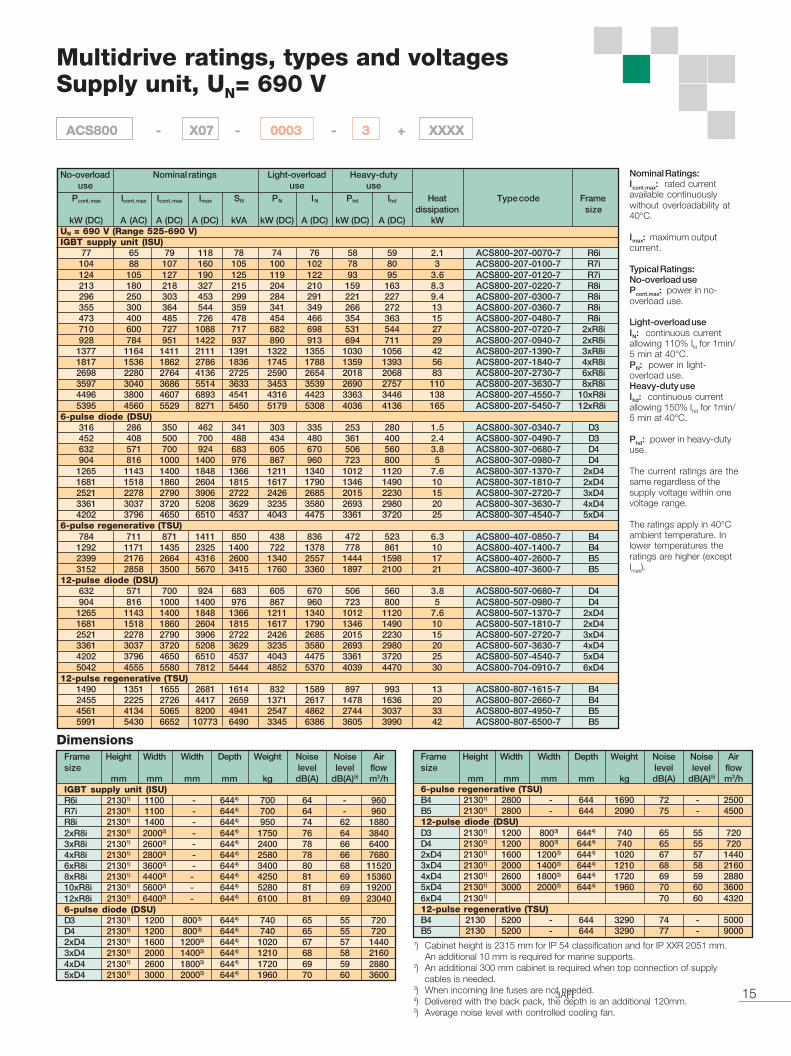
153AFE 68248531 REV A EN 31.3.2004
Multidrive ratings, types and voltagesSupply unit, UN= 690 V
Pcont. max Icont. max Icont. max Imax SN PN IN Phd Ihd Heat Type code Framedissipation size
kW (DC) A (AC) A (DC) A (DC) kVA kW (DC) A (DC) kW (DC) A (DC) kWUN = 690 V (Range 525-690 V)IGBT supply unit (ISU)
77 65 79 118 78 74 76 58 59 2.1 ACS800-207-0070-7 R6i104 88 107 160 105 100 102 78 80 3 ACS800-207-0100-7 R7i124 105 127 190 125 119 122 93 95 3.6 ACS800-207-0120-7 R7i213 180 218 327 215 204 210 159 163 8.3 ACS800-207-0220-7 R8i296 250 303 453 299 284 291 221 227 9.4 ACS800-207-0300-7 R8i355 300 364 544 359 341 349 266 272 13 ACS800-207-0360-7 R8i473 400 485 726 478 454 466 354 363 15 ACS800-207-0480-7 R8i710 600 727 1088 717 682 698 531 544 27 ACS800-207-0720-7 2xR8i928 784 951 1422 937 890 913 694 711 29 ACS800-207-0940-7 2xR8i
1377 1164 1411 2111 1391 1322 1355 1030 1056 42 ACS800-207-1390-7 3xR8i1817 1536 1862 2786 1836 1745 1788 1359 1393 56 ACS800-207-1840-7 4xR8i2698 2280 2764 4136 2725 2590 2654 2018 2068 83 ACS800-207-2730-7 6xR8i3597 3040 3686 5514 3633 3453 3539 2690 2757 110 ACS800-207-3630-7 8xR8i4496 3800 4607 6893 4541 4316 4423 3363 3446 138 ACS800-207-4550-7 10xR8i5395 4560 5529 8271 5450 5179 5308 4036 4136 165 ACS800-207-5450-7 12xR8i
6-pulse diode (DSU)316 286 350 462 341 303 335 253 280 1.5 ACS800-307-0340-7 D3452 408 500 700 488 434 480 361 400 2.4 ACS800-307-0490-7 D3632 571 700 924 683 605 670 506 560 3.8 ACS800-307-0680-7 D4904 816 1000 1400 976 867 960 723 800 5 ACS800-307-0980-7 D4
1265 1143 1400 1848 1366 1211 1340 1012 1120 7.6 ACS800-307-1370-7 2xD41681 1518 1860 2604 1815 1617 1790 1346 1490 10 ACS800-307-1810-7 2xD42521 2278 2790 3906 2722 2426 2685 2015 2230 15 ACS800-307-2720-7 3xD43361 3037 3720 5208 3629 3235 3580 2693 2980 20 ACS800-307-3630-7 4xD44202 3796 4650 6510 4537 4043 4475 3361 3720 25 ACS800-307-4540-7 5xD4
6-pulse regenerative (TSU)784 711 871 1411 850 438 836 472 523 6.3 ACS800-407-0850-7 B4
1292 1171 1435 2325 1400 722 1378 778 861 10 ACS800-407-1400-7 B42399 2176 2664 4316 2600 1340 2557 1444 1598 17 ACS800-407-2600-7 B53152 2858 3500 5670 3415 1760 3360 1897 2100 21 ACS800-407-3600-7 B5
12-pulse diode (DSU)632 571 700 924 683 605 670 506 560 3.8 ACS800-507-0680-7 D4904 816 1000 1400 976 867 960 723 800 5 ACS800-507-0980-7 D4
1265 1143 1400 1848 1366 1211 1340 1012 1120 7.6 ACS800-507-1370-7 2xD41681 1518 1860 2604 1815 1617 1790 1346 1490 10 ACS800-507-1810-7 2xD42521 2278 2790 3906 2722 2426 2685 2015 2230 15 ACS800-507-2720-7 3xD43361 3037 3720 5208 3629 3235 3580 2693 2980 20 ACS800-507-3630-7 4xD44202 3796 4650 6510 4537 4043 4475 3361 3720 25 ACS800-507-4540-7 5xD45042 4555 5580 7812 5444 4852 5370 4039 4470 30 ACS800-704-0910-7 6xD4
12-pulse regenerative (TSU)1490 1351 1655 2681 1614 832 1589 897 993 13 ACS800-807-1615-7 B42455 2225 2726 4417 2659 1371 2617 1478 1636 20 ACS800-807-2660-7 B44561 4134 5065 8200 4941 2547 4862 2744 3037 33 ACS800-807-4950-7 B55991 5430 6652 10773 6490 3345 6386 3605 3990 42 ACS800-807-6500-7 B5
Nominal ratingsNo-overloaduse
Light-overloaduse
Heavy-dutyuse
DimensionsFrame Height Width Width Depth Weight Noise Noise Airsize level level flow
mm mm mm mm kg dB(A) dB(A)5) m3/hIGBT supply unit (ISU)R6i 21301) 1100 - 6444) 700 64 - 960R7i 21301) 1100 - 6444) 700 64 - 960R8i 21301) 1400 - 6444) 950 74 62 18802xR8i 21301) 20002) - 6444) 1750 76 64 38403xR8i 21301) 26002) - 6444) 2400 78 66 64004xR8i 21301) 28002) - 6444) 2580 78 66 76806xR8i 21301) 36002) - 6444) 3400 80 68 115208xR8i 21301) 44002) - 6444) 4250 81 69 1536010xR8i 21301) 56002) - 6444) 5280 81 69 1920012xR8i 21301) 64002) - 6444) 6100 81 69 230406-pulse diode (DSU)D3 21301) 1200 8003) 6444) 740 65 55 720D4 21301) 1200 8003) 6444) 740 65 55 7202xD4 21301) 1600 12003) 6444) 1020 67 57 14403xD4 21301) 2000 14003) 6444) 1210 68 58 21604xD4 21301) 2600 18003) 6444) 1720 69 59 28805xD4 21301) 3000 20003) 6444) 1960 70 60 3600
6-pulse regenerative (TSU)B4 21301) 2800 - 644 1690 72 - 2500B5 21301) 2800 - 644 2090 75 - 450012-pulse diode (DSU)D3 21301) 1200 8003) 6444) 740 65 55 720D4 21301) 1200 8003) 6444) 740 65 55 7202xD4 21301) 1600 12003) 6444) 1020 67 57 14403xD4 21301) 2000 14003) 6444) 1210 68 58 21604xD4 21301) 2600 18003) 6444) 1720 69 59 28805xD4 21301) 3000 20003) 6444) 1960 70 60 36006xD4 21301) 70 60 432012-pulse regenerative (TSU)B4 2130 5200 - 644 3290 74 - 5000B5 2130 5200 - 644 3290 77 - 9000
Nominal Ratings:Icont.max: rated currentavailable continuouslywithout overloadability at40°C.
Imax: maximum outputcurrent.
Typical Ratings:No-overload usePcont.max: power in no-overload use.
Light-overload useIN: continuous currentallowing 110% IN for 1min/5 min at 40°C.PN: power in light-overload use.Heavy-duty useIhd: continuous currentallowing 150% Ihd for 1min/5 min at 40°C.
Phd: power in heavy-dutyuse.
The current ratings are thesame regardless of thesupply voltage within onevoltage range.
The ratings apply in 40°Cambient temperature. Inlower temperatures theratings are higher (exceptImax).
Frame Height Width Width Depth Weight Noise Noise Airsize level level flow
mm mm mm mm kg dB(A) dB(A)5) m3/h
ACS800 - X07 - 0003 - 3 + XXXX
1) Cabinet height is 2315 mm for IP 54 classification and for IP XXR 2051 mm.An additional 10 mm is required for marine supports.
2) An additional 300 mm cabinet is required when top connection of supplycables is needed.
3) When incoming line fuses are not needed.4) Delivered with the back pack, the depth is an additional 120mm.5) Average noise level with controlled cooling fan.
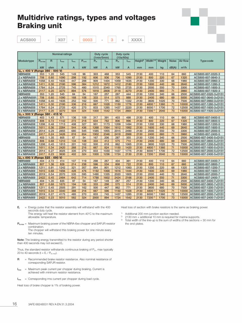
16 3AFE 68248531 REV A EN 31.3.2004
Multidrive ratings, types and voltagesBraking unit
Er = Energy pulse that the resistor assembly will withstand with the 400seconds duty cycle.This energy will heat the resistor element from 40°C to the maximumallowable temperature.
Pbr,max = Maximum braking power of the NBRA-6xx chopper and SAFUR resistorcombination.The chopper will withstand this braking power for one minute everyten minutes.
Note: The braking energy transmitted to the resistor during any period shorterthan 400 seconds may not exceed Er.
Thus, the standard resistor withstands continuous braking of Pbr, max typically20 to 40 seconds (t = Er / Pbr,max).
R = Recommended brake resistor resistance. Also nominal resistance ofcorresponding SAFUR resistor.
Imax = Maximum peak current per chopper during braking. Current isachieved with minimum resistor resistance.
Irms = Corresponding rms current per chopper during load cycle.
Heat loss of brake chopper is 1% of braking power.
Heat loss of section with brake resistors is the same as braking power.
1) Additional 200 mm junction section needed.2) 2130 mm + additional 10 mm is required for marine supports.3) Total width of the line-up is the sum of widths of the sections + 30 mm for
the end plates.
Nominal ratings Duty cycle Duty cycle(1min/5min) (10s/60s)
Module type Pbr.max R Imax Irms. Pcont. Pbr. Irms Pbr. Irms Height2) Width1) 3) Weight Noise Air flow Type code
kW ohm A A kW kW A kW A mm mm kg dB(A) m3/hUN = 400 V (Range 380 - 500 V)NBRA659 353 1.20 545 149 96 303 468 353 545 2130 400 110 64 660 ACS800-607-0320-32 x NBRA659 706 0.60 1090 298 192 606 936 706 1090 2130 800 220 67 1320 ACS800-607-0640-33 x NBRA659 1058 0.40 1635 447 288 909 1404 1059 1635 2130 1200 330 68 1980 ACS800-607-0960-34 x NBRA659 1411 0.30 2180 596 384 1212 1872 1412 2180 2130 1600 440 69 2640 ACS800-607-1280-35 x NBRA659 1764 0.24 2725 745 480 1515 2340 1765 2725 2130 2000 550 70 3300 ACS800-607-1600-36 x NBRA659 2117 0.20 3270 894 576 1818 2808 2118 3270 2130 2400 660 71 3960 ACS800-607-1920-3NBRA659 353 1.20 545 84 54 167 257 287 444 2130 1200 340 66 2500 ACS800-607-0320-3+D1512 x NBRA6591 706 0.60 1090 168 108 333 514 575 888 2130 2400 680 69 5000 ACS800-607-0640-3+D1513 x NBRA659 1058 0.40 1635 252 162 500 771 862 1332 2130 3600 1020 70 7500 ACS800-607-0960-3+D1514 x NBRA659 1411 0.30 2180 336 216 667 1028 1150 1776 2130 4800 1) 1360 71 10000 ACS800-607-1280-3+D1515 x NBRA659 1764 0.24 2725 420 270 833 1285 1437 2220 2130 6000 1) 1700 72 12500 ACS800-607-1600-3+D1516 x NBRA659 2117 0.20 3270 504 324 1000 1542 1724 2664 2130 7200 1) 2040 73 15000 ACS800-607-1920-3+D151UN = 500 V (Range 380 - 415 V)NBRA659 403 1.43 571 136 109 317 391 403 498 2130 400 110 64 660 ACS800-607-0400-52 x NBRA659 806 0.72 1142 272 218 634 782 806 996 2130 800 220 67 1320 ACS800-607-0800-53 x NBRA659 1208 0.48 1713 408 327 951 1173 1209 1494 2130 1200 330 68 1980 ACS800-607-1200-54 x NBRA659 1611 0.36 2284 544 436 1268 1564 1612 1992 2130 1600 440 69 2640 ACS800-607-1600-55 x NBRA659 2014 0.29 2855 680 545 1585 1955 2015 2490 2130 2000 550 70 3300 ACS800-607-2000-56 x NBRA659 2417 0.24 3426 816 654 1902 2346 2418 2988 2130 2400 660 71 3960 ACS800-607-2400-5NBRA659 403 1.35 605 67 54 167 206 287 355 2130 1200 340 66 2500 ACS800-607-0400-5+D1512 x NBRA659 806 0.68 1210 134 108 333 412 575 710 2130 2400 680 69 5000 ACS800-607-0800-5+D1513 x NBRA659 1208 0.45 1815 201 162 500 618 862 1065 2130 3600 1020 70 7500 ACS800-607-1200-5+D1514 x NBRA659 1611 0.34 2420 268 216 667 824 1150 1420 2130 4800 1) 1360 71 10000 ACS800-607-1600-5+D1515 x NBRA659 2014 0.27 3025 335 270 833 1030 1437 1775 2130 6000 1) 1700 72 12500 ACS800-607-2000-5+D1516 x NBRA659 2417 0.23 3630 402 324 1000 1236 1724 2130 2130 7200 1) 2040 73 15000 ACS800-607-2400-5+D151UN = 690 V (Range 525 - 690 V)NBRA669 404 2.72 414 107 119 298 267 404 361 2130 400 110 64 660 ACS800-607-0400-72 x NBRA669 807 1.36 828 214 238 596 534 808 722 2130 800 110 67 660 ACS800-607-0800-73 x NBRA669 1211 0.91 1242 321 357 894 801 1212 1083 2130 1200 220 68 1320 ACS800-607-1200-74 x NBRA669 1615 0.68 1656 428 476 1192 1068 1616 1444 2130 1600 330 69 1980 ACS800-607-1600-75 x NBRA669 2019 0.54 2070 535 595 1490 1335 2020 1805 2130 2000 440 70 2640 ACS800-607-2000-76 x NBRA669 2422 0.45 2484 642 714 1788 1602 2424 2166 2130 2400 550 71 3300 ACS800-607-2400-7NBRA669 404 1.35 835 97 54 167 149 287 257 2130 1200 340 66 2500 ACS800-607-0400-7+D1512 x NBRA669 807 0.68 1670 194 108 333 298 575 514 2130 2400 340 69 5000 ACS800-607-0800-7+D1513 x NBRA669 1211 0.45 2505 291 162 500 447 862 771 2130 3600 680 70 7500 ACS800-607-1200-7+D1514 x NBRA669 1615 0.34 3340 388 216 667 596 1150 1028 2130 4800 1) 1020 71 10000 ACS800-607-1600-7+D1515 x NBRA6691 2019 0.27 4175 485 270 833 745 1437 1285 2130 6000 1) 1360 72 12500 ACS800-607-2000-7+D1516 x NBRA669 2422 0.23 5010 582 324 2000 894 1724 1542 2130 7200 1) 1700 73 15000 ACS800-607-2400-7+D151
ACS800 - X07 - 0003 - 3 + XXXX
173AFE 68248531 REV A EN 31.3.2004
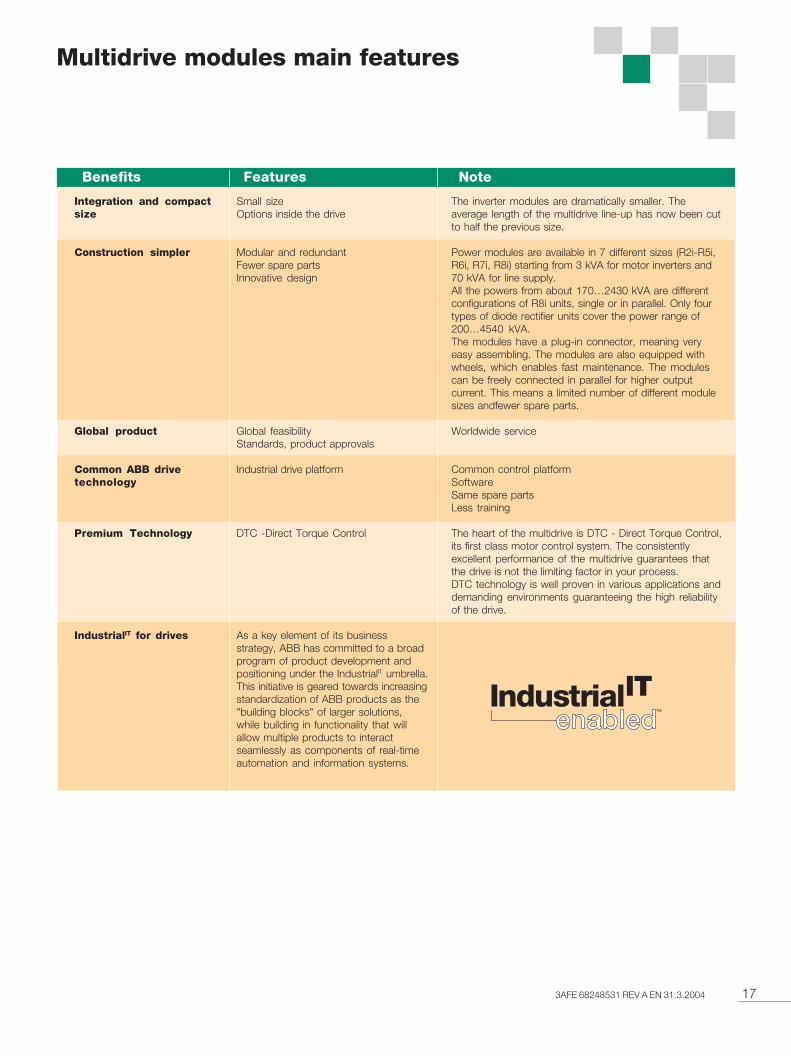
Multidrive modules main features
NoteBenefits Features
Small sizeOptions inside the drive
Modular and redundantFewer spare partsInnovative design
Global feasibilityStandards, product approvals
Industrial drive platform
DTC -Direct Torque Control
As a key element of its businessstrategy, ABB has committed to a broadprogram of product development andpositioning under the IndustrialIT umbrella.This initiative is geared towards increasingstandardization of ABB products as the"building blocks" of larger solutions,while building in functionality that willallow multiple products to interactseamlessly as components of real-timeautomation and information systems.
The inverter modules are dramatically smaller. Theaverage length of the multidrive line-up has now been cutto half the previous size.
Power modules are available in 7 different sizes (R2i-R5i,R6i, R7i, R8i) starting from 3 kVA for motor inverters and70 kVA for line supply.All the powers from about 170…2430 kVA are differentconfigurations of R8i units, single or in parallel. Only fourtypes of diode rectifier units cover the power range of200…4540 kVA.The modules have a plug-in connector, meaning veryeasy assembling. The modules are also equipped withwheels, which enables fast maintenance. The modulescan be freely connected in parallel for higher outputcurrent. This means a limited number of different modulesizes andfewer spare parts.
Worldwide service
Common control platformSoftwareSame spare partsLess training
The heart of the multidrive is DTC - Direct Torque Control,its first class motor control system. The consistentlyexcellent performance of the multidrive guarantees thatthe drive is not the limiting factor in your process.DTC technology is well proven in various applications anddemanding environments guaranteeing the high reliabilityof the drive.
Integration and compactsize
Construction simpler
Global product
Common ABB drivetechnology
Premium Technology
IndustrialIT for drives
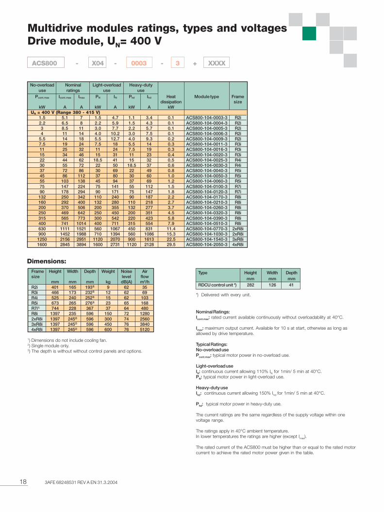
18 3AFE 68248531 REV A EN 31.3.2004
Multidrive modules ratings, types and voltagesDrive module, UN= 400 V
Pcont. max Icont. max Imax PN IN Phd Ihd Heat Module type Framedissipation size
kW A A kW A kW A kW UN = 400 V (Range 380 - 415 V)
1.5 5.1 7 1.5 4.7 1.1 3.4 0.1 ACS800-104-0003-3 R2i2.2 6.5 8 2.2 5.9 1.5 4.3 0.1 ACS800-104-0004-3 R2i3 8.5 11 3.0 7.7 2.2 5.7 0.1 ACS800-104-0005-3 R2i4 11 14 4.0 10.2 3.0 7.5 0.1 ACS800-104-0006-3 R2i
5.5 14 18 5.5 12.7 4.0 9.3 0.2 ACS800-104-0009-3 R2i7.5 19 24 7.5 18 5.5 14 0.3 ACS800-104-0011-3 R3i11 25 32 11 24 7.5 19 0.3 ACS800-104-0016-3 R3i15 34 46 15 31 11 23 0.4 ACS800-104-0020-3 R3i22 44 62 18.5 41 15 32 0.5 ACS800-104-0025-3 R4i30 55 72 22 50 18.5 37 0.6 ACS800-104-0030-3 R4i37 72 86 30 69 22 49 0.8 ACS800-104-0040-3 R5i45 86 112 37 80 30 60 1.0 ACS800-104-0050-3 R5i55 103 138 45 94 37 69 1.2 ACS800-104-0060-3 R5i75 147 224 75 141 55 112 1.5 ACS800-104-0100-3 R7i90 178 294 90 171 75 147 1.8 ACS800-104-0120-3 R7i
132 250 342 110 240 90 187 2.2 ACS800-104-0170-3 R8i160 292 400 132 280 110 218 2.7 ACS800-104-0210-3 R8i200 370 506 200 355 132 277 3.7 ACS800-104-0260-3 R8i250 469 642 250 450 200 351 4.5 ACS800-104-0320-3 R8i315 565 773 300 542 220 423 5.8 ACS800-104-0390-3 R8i400 741 1014 400 711 315 554 7.9 ACS800-104-0510-3 R8i630 1111 1521 560 1067 450 831 11.4 ACS800-104-0770-3 2xR8i900 1452 1988 710 1394 560 1086 15.3 ACS800-104-1030-3 2xR8i
1250 2156 2951 1120 2070 900 1613 22.5 ACS800-104-1540-3 3xR8i1600 2845 3894 1600 2731 1120 2128 29.5 ACS800-104-2050-3 4xR8i
1) Dimensions do not include cooling fan.2) Single module only.3) The depth is without without control panels and options.
Type Height Width Depthmm mm mm
RDCU control unit *) 282 126 41
Nominal Ratings:Icont.max: rated current available continuously without overloadability at 40°C.
Imax: maximum output current. Available for 10 s at start, otherwise as long asallowed by drive temperature.
Typical Ratings:No-overload usePcont.max: typical motor power in no-overload use.
Light-overload useIN: continuous current allowing 110% IN for 1min/ 5 min at 40°C.PN: typical motor power in light-overload use.
Heavy-duty useIhd: continuous current allowing 150% Ihd for 1min/ 5 min at 40°C.
Phd: typical motor power in heavy-duty use.
The current ratings are the same regardless of the supply voltage within onevoltage range.
The ratings apply in 40°C ambient temperature.In lower temperatures the ratings are higher (except Imax).
The rated current of the ACS800 must be higher than or equal to the rated motorcurrent to achieve the rated motor power given in the table.
Dimensions:Frame Height Width Depth Weight Noise Airsize level flow
mm mm mm kg dB(A) m3/hR2i 401 165 1933) 9 62 35R3i 466 173 2323) 12 62 69R4i 525 240 2523) 15 62 103R5i 673 265 2763) 23 65 168R7i1) 744 228 367 37 64 480R8i 1397 235 596 150 72 12802xR8i 1397 2452) 596 300 74 25603xR8i 1397 2452) 596 450 76 38404xR8i 1397 2452) 596 600 76 5120
Nominalratings
No-overloaduse
Light-overloaduse
Heavy-dutyuse
*) Delivered with every unit.
ACS800 - X04 - 0003 - 3 + XXXX
193AFE 68248531 REV A EN 31.3.2004
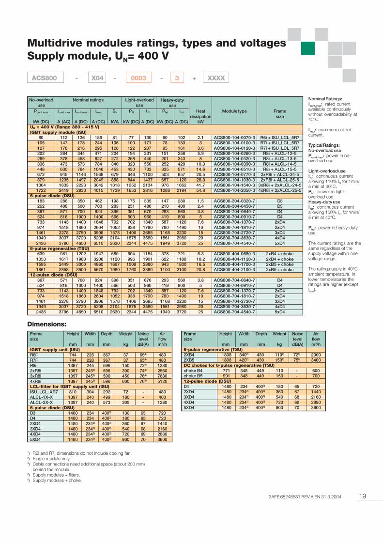
Multidrive modules ratings, types and voltagesSupply module, UN= 400 V
1) R6i and R7i dimensions do not include cooling fan.2) Single module only.3) Cable connections need additional space (about 200 mm)
behind the module.4) Supply modules + filters.5) Supply modules + choke.
Dimensions:
Pcont. max Icont. max Icont. max Imax SN PN IN Phd Ihd Heat Module type Framedissipation size
kW (DC) A (AC) A (DC) A (DC) kVA kW (DC) A (DC) kW (DC) A (DC) kWUN = 400 V (Range 380 - 415 V)IGBT supply module (ISU)
80 112 136 186 81 77 130 60 102 2.1 ACS800-104-0070-3 R6i + ISU_LCL_5R7105 147 178 244 106 100 171 78 133 3 ACS800-104-0100-3 R7i + ISU_LCL_5R7127 178 216 295 128 122 207 95 161 3.6 ACS800-104-0120-3 R7i + ISU_LCL_5R7202 284 344 471 204 194 331 151 258 5.9 ACS800-104-0260-3 R8i + ALCL-12-5269 378 458 627 272 258 440 201 343 8 ACS800-104-0320-3 R8i + ALCL-13-5336 473 573 784 340 323 550 252 429 10.3 ACS800-104-0390-3 R8i + ALCL-14-5448 630 764 1046 453 430 733 335 571 14.6 ACS800-104-0510-3 R8i + ALCL-15-5672 945 1146 1568 679 646 1100 503 857 20.5 ACS800-104-0770-3 2xR8i + ALCL-24-5879 1235 1497 2049 888 844 1437 657 1120 28.3 ACS800-104-1030-3 2xR8i + ALCL-25-51304 1833 2223 3042 1318 1252 2134 976 1662 41.7 ACS800-104-1540-3 3xR8i + 2xALCL-24-51722 2419 2933 4015 1739 1653 2816 1288 2194 54.8 ACS800-104-2050-3 4xR8i + 2xALCL-25-5
6-pulse diode (DSU)183 286 350 462 198 175 335 147 280 1.5 ACS800-304-0320-7 D3262 408 500 700 283 251 480 210 400 2.4 ACS800-304-0450-7 D3367 571 700 924 396 351 670 293 560 3.8 ACS800-704-0640-7 D4524 816 1000 1400 566 503 960 419 800 5 ACS800-704-0910-7 D4733 1143 1400 1848 792 702 1340 587 1120 7.6 ACS800-704-1370-7 2xD4974 1518 1860 2604 1052 938 1790 780 1490 10 ACS800-704-1810-7 2xD41461 2278 2790 3906 1578 1406 2685 1168 2230 15 ACS800-704-2720-7 3xD41949 3037 3720 5208 2104 1875 3580 1561 2980 20 ACS800-704-3630-7 4xD42436 3796 4650 6510 2630 2344 4475 1949 3720 25 ACS800-704-4540-7 5xD4
6-pulse regenerative (TSU)639 981 1202 1947 680 604 1154 378 721 6.3 ACS800-404-0680-3 2xB4 + choke1053 1617 1980 3208 1120 996 1901 622 1188 10.2 ACS800-404-1120-3 2xB4 + choke1595 2449 3000 4860 1697 1509 2880 943 1800 16.5 ACS800-404-1700-3 2xB5 + choke1861 2858 3500 5670 1980 1760 3360 1100 2100 20.8 ACS800-404-2100-3 2xB5 + choke
12-pulse diode (DSU)367 571 700 924 396 351 670 293 560 3.8 ACS800-704-0640-7 D4524 816 1000 1400 566 503 960 419 800 5 ACS800-704-0910-7 D4733 1143 1400 1848 792 702 1340 587 1120 7.6 ACS800-704-1370-7 2xD4974 1518 1860 2604 1052 938 1790 780 1490 10 ACS800-704-1810-7 2xD41461 2278 2790 3906 1578 1406 2685 1168 2230 15 ACS800-704-2720-7 3xD41949 3037 3720 5208 2104 1875 3580 1561 2980 20 ACS800-704-3630-7 4xD42436 3796 4650 6510 2630 2344 4475 1949 3720 25 ACS800-704-4540-7 5xD4
Frame Height Width Depth Weight Noise Airsize level flow
mm mm mm kg dB(A) m3/hIGBT supply unit (ISU)R6i1) 744 228 367 37 654) 480R7i1) 744 228 367 37 654) 480R8i 1397 245 596 150 724) 12802xR8i 1397 2452) 596 300 744) 25603xR8i 1397 2452) 596 450 764) 76804xR8i 1397 2452) 596 600 764) 5120LCL-filter for IGBT supply unit (ISU)ISU_LCL_XR7 810 304 292 72 - 480ALCL-1X-X 1397 240 499 180 - 400ALCL-2X-X 1397 240 573 305 - 12806-pulse diode (DSU)D3 1480 234 4003) 130 65 720D4 1480 234 4003) 180 65 7202XD4 1480 2342) 4003) 360 67 14403XD4 1480 2342) 4003) 540 68 21604XD4 1480 2342) 4003) 720 69 28805XD4 1480 2342) 4003) 900 70 3600
Nominal ratingsNo-overloaduse
Light-overloaduse
Heavy-dutyuse
Frame Height Width Depth Weight Noise Airsize level flow
mm mm mm kg dB(A) m3/h6-pulse regenerative (TSU)2XB4 1808 3402) 430 1102) 725) 20002XB5 1808 4202) 430 1502) 755) 3400DC chokes for 6-pulse regenerative (TSU)choke B4 771 348 449 110 - 600choke B5 991 348 449 150 - 70012-pulse diode (DSU)D4 1480 234 4003) 180 65 7202XD4 1480 2342) 4003) 360 67 14403XD4 1480 2342) 4003) 540 68 21604XD4 1480 2342) 4003) 720 69 28805XD4 1480 2342) 4003) 900 70 3600
Nominal Ratings:Icont.max: rated currentavailable continuouslywithout overloadability at40°C.
Imax: maximum outputcurrent.
Typical Ratings:No-overload usePcont.max: power in no-overload use.
Light-overload useIN: continuous currentallowing 110% IN for 1min/5 min at 40°C.PN: power in light-overload use.Heavy-duty useIhd: continuous currentallowing 150% Ihd for 1min/5 min at 40°C.
Phd: power in heavy-dutyuse.
The current ratings are thesame regardless of thesupply voltage within onevoltage range.
The ratings apply in 40°Cambient temperature. Inlower temperatures theratings are higher (exceptImax).
ACS800 - X04 - 0003 - 3 + XXXX
20 3AFE 68248531 REV A EN 31.3.2004
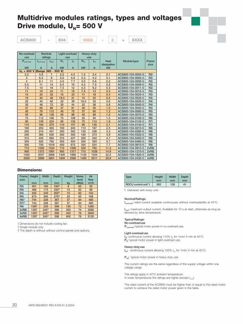
Multidrive modules ratings, types and voltagesDrive module, UN= 500 V
1) Dimensions do not include cooling fan.2) Single module only.3) The depth is without without control panels and options.
Type Height Width Depthmm mm mm
RDCU control unit *) 282 126 41
Dimensions:Frame Height Width Depth Weight Noise Airsize level flow
mm mm mm kg dB(A) m3/hR2i 401 165 1933) 9 62 35R3i 466 173 2323) 12 62 69R4i 525 240 2523) 15 62 103R5i 673 265 2763) 23 65 168R6i1) 744 228 367 37 64 480R7i1) 744 228 367 37 64 480R8i 1397 235 596 150 72 12802xR8i 1397 2452) 596 300 74 25603xR8i 1397 2452) 596 450 76 38404xR8i 1397 2452) 596 600 76 5120
Nominal Ratings:Icont.max: rated current available continuously without overloadability at 40°C.
Imax: maximum output current. Available for 10 s at start, otherwise as long asallowed by drive temperature.
Typical Ratings:No-overload usePcont.max: typical motor power in no-overload use.
Light-overload useIN: continuous current allowing 110% IN for 1min/ 5 min at 40°C.PN: typical motor power in light-overload use.
Heavy-duty useIhd: continuous current allowing 150% Ihd for 1min/ 5 min at 40°C.
Phd: typical motor power in heavy-duty use.
The current ratings are the same regardless of the supply voltage within onevoltage range.
The ratings apply in 40°C ambient temperature.In lower temperatures the ratings are higher (except Imax).
The rated current of the ACS800 must be higher than or equal to the rated motorcurrent to achieve the rated motor power given in the table.
*) Delivered with every unit.
Pcont. max Icont. max Imax PN IN Phd Ihd Heat Module type Framedissipation size
kW A A kW A kW A kW UN = 500 V (Range 380 - 500 V)
2.2 4.9 7 2.2 4.5 1.5 3.4 0.1 ACS800-104-0004-5 R2i3 6.2 8 3.0 5.6 2.2 4.2 0.1 ACS800-104-0005-5 R2i4 8.1 11 4.0 7.7 3.0 5.6 0.2 ACS800-104-0006-5 R2i
5.5 11 14 5.5 10 4.0 7.5 0.2 ACS800-104-0009-5 R2i7.5 13 18 7.5 12 5.5 9.2 0.3 ACS800-104-0011-5 R2i11 19 24 11 18 7.5 13 0.3 ACS800-104-0016-5 R3i15 25 32 15 23 11 18 0.4 ACS800-104-0020-5 R3i19 34 46 18.5 31 15 23 0.5 ACS800-104-0025-5 R3i22 42 62 22 39 18.5 32 0.6 ACS800-104-0030-5 R4i30 48 72 30 44 22 36 0.8 ACS800-104-0040-5 R4i37 65 86 37 61 30 50 1.0 ACS800-104-0050-5 R5i45 79 112 45 75 37 60 1.2 ACS800-104-0060-5 R5i55 96 138 55 88 45 69 1.4 ACS800-104-0070-5 R5i75 112 168 75 108 55 84 1.5 ACS800-104-0100-5 R6i90 135 224 90 130 75 112 1.8 ACS800-104-0120-5 R7i
110 164 270 110 157 90 135 2.1 ACS800-104-0140-5 R7i160 250 363 160 240 110 187 2.5 ACS800-104-0210-5 R8i200 315 457 200 302 132 236 3.3 ACS800-104-0260-5 R8i250 365 530 250 350 160 273 3.9 ACS800-104-0320-5 R8i315 455 660 315 437 200 340 4.7 ACS800-104-0400-5 R8i355 525 762 355 504 250 393 5.7 ACS800-104-0460-5 R8i500 700 1016 450 672 355 524 7.7 ACS800-104-0610-5 R8i710 1050 1524 710 1008 500 785 11.3 ACS800-104-0910-5 2xR8i900 1372 1991 900 1317 710 1026 14.9 ACS800-104-1210-5 2xR8i
1400 2037 2956 1400 1956 1120 1524 22.0 ACS800-104-1820-5 3xR8i2000 2688 3901 1800 2580 1400 2011 28.9 ACS800-104-2430-5 4xR8i
Nominalratings
No-overloaduse
Light-overloaduse
Heavy-dutyuse
ACS800 - X04 - 0003 - 3 + XXXX
213AFE 68248531 REV A EN 31.3.2004
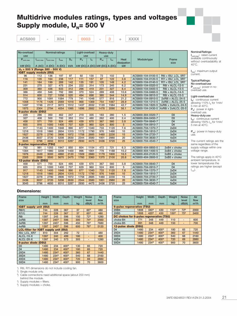
Multidrive modules ratings, types and voltagesSupply module, UN= 500 V
1) R6i, R7i dimensions do not include cooling fan.2) Single module only.3) Cable connections need additional space (about 200 mm)
behind the module.4) Supply modules + filters.5) Supply modules + choke.
Dimensions:Frame Height Width Depth Weight Noise Airsize level flow
mm mm mm kg dB(A) m3/hIGBT supply unit (ISU)R6i1) 744 228 367 37 654) 480R7i1) 744 228 367 37 654) 480R8i 1397 245 596 150 724) 12802xR8i 1397 2452) 596 300 744) 25603xR8i 1397 2452) 596 450 764) 76804xR8i 1397 2452) 596 600 764) 5120LCL-filter for IGBT supply unit (ISU)ISU_LCL_XR7 810 304 292 72 - 480ALCL-1X-X 1397 240 499 180 - 400ALCL-2X-X 1397 240 573 305 - 12806-pulse diode (DSU)D3 1480 234 4003) 130 65 720D4 1480 234 4003) 180 65 7202XD4 1480 2342) 4003) 360 67 14403XD4 1480 2342) 4003) 540 68 21604XD4 1480 2342) 4003) 720 69 28805XD4 1480 2342) 4003) 900 70 3600
Frame Height Width Depth Weight Noise Airsize level flow
mm mm mm kg dB(A) m3/h6-pulse regenerative (TSU)2XB4 1808 3402) 430 1102) 725) 20002XB5 1808 4202) 430 1502) 755) 3400DC chokes for 6-pulse regenerative (TSU)choke B4 771 348 449 110 - 600choke B5 991 348 449 150 - 70012-pulse diode (DSU)D4 1480 234 4003) 180 65 7202XD4 1480 2342) 4003) 360 67 14403XD4 1480 2342) 4003) 540 68 21604XD4 1480 2342) 4003) 720 69 28805XD4 1480 2342) 4003) 900 70 3600
Pcont. max Icont. max Icont. max Imax SN PN IN Phd Ihd Heat Module type Framedissipation size
kW (DC) A (AC) A (DC) A (DC) kVA kW (DC) A (DC) kW (DC) A (DC) kWUN = 500 V (Range 380 - 500 V)IGBT supply module (ISU)
96 112 136 197 97 92 130 72 102 3 ACS800-104-0100-5 R6i + ISU_LCL_5R7116 135 164 238 117 111 157 87 122 3.6 ACS800-104-0120-5 R7i + ISU_LCL_5R7141 164 199 289 142 135 191 105 149 4.2 ACS800-104-0140-5 R7i + ISU_LCL_5R7231 270 327 475 234 222 314 173 245 6.2 ACS800-104-0320-5 R8i + ALCL-12-5309 360 436 633 312 296 419 231 327 8.4 ACS800-104-0400-5 R8i + ALCL-13-5386 450 546 792 390 370 524 289 408 10.6 ACS800-104-0460-5 R8i + ALCL-14-5514 600 727 1056 520 494 698 385 544 14.9 ACS800-104-0610-5 R8i + ALCL-15-5772 900 1091 1584 779 741 1048 577 816 21.2 ACS800-104-0910-5 2xR8i + ALCL-24-5
1008 1176 1426 2069 1018 968 1369 754 1067 28.9 ACS800-104-1210-5 2xR8i + ALCL-25-51497 1746 2117 3072 1512 1437 2032 1120 1584 42.7 ACS800-104-1820-5 3xR8i + 2xALCL-24-51975 2304 2794 4054 1995 1896 2682 1478 2090 56.1 ACS800-104-2430-5 4xR8i + 2xALCL-25-5
6-pulse diode (DSU)229 286 350 462 247 219 335 183 280 1.5 ACS800-304-0320-7 D3327 408 500 700 353 314 480 262 400 2.4 ACS800-304-0450-7 D3458 571 700 924 495 439 670 367 560 3.8 ACS800-704-0640-7 D4655 816 1000 1400 707 629 960 524 800 5 ACS800-704-0910-7 D4917 1143 1400 1848 990 877 1340 733 1120 7.6 ACS800-704-1370-7 2xD4
1218 1518 1860 2604 1315 1172 1790 976 1490 10 ACS800-704-1810-7 2xD41827 2278 2790 3906 1972 1758 2685 1460 2230 15 ACS800-704-2720-7 3xD42436 3037 3720 5208 2630 2344 3580 1951 2980 20 ACS800-704-3630-7 4xD43045 3796 4650 6510 3287 2930 4475 2436 3720 25 ACS800-704-4540-7 5xD4
6-pulse regenerative (TSU)792 981 1202 1947 850 604 1154 472 721 6.3 ACS800-404-0850-5 2xB4 + choke
1304 1617 1980 3208 1400 996 1901 778 1188 10.2 ACS800-404-1400-5 2xB4 + choke1976 2449 3000 4860 2120 1509 2880 1179 1800 16.5 ACS800-404-2120-5 2xB5 + choke2305 2858 3500 5670 2475 1760 3360 1375 2100 20.8 ACS800-404-2600-5 2xB5 + choke
12-pulse diode (DSU)458 571 700 924 495 439 670 367 560 3.8 ACS800-704-0640-7 D4655 816 1000 1400 707 629 960 524 800 5 ACS800-704-0910-7 D4917 1143 1400 1848 990 877 1340 733 1120 7.6 ACS800-704-1370-7 2xD4
1218 1518 1860 2604 1315 1172 1790 976 1490 10 ACS800-704-1810-7 2xD41827 2278 2790 3906 1972 1758 2685 1460 2230 15 ACS800-704-2720-7 3xD42436 3037 3720 5208 2630 2344 3580 1951 2980 20 ACS800-704-3630-7 4xD43045 3796 4650 6510 3287 2930 4475 2436 3720 25 ACS800-704-4540-7 5xD4
Nominal ratingsNo-overloaduse
Light-overloaduse
Heavy-dutyuse
Nominal Ratings:Icont.max: rated currentavailable continuouslywithout overloadability at40°C.
Imax: maximum outputcurrent.
Typical Ratings:No-overload usePcont.max: power in no-overload use.
Light-overload useIN: continuous currentallowing 110% IN for 1min/5 min at 40°C.PN: power in light-overload use.Heavy-duty useIhd: continuous currentallowing 150% Ihd for 1min/5 min at 40°C.
Phd: power in heavy-dutyuse.
The current ratings are thesame regardless of thesupply voltage within onevoltage range.
The ratings apply in 40°Cambient temperature. Inlower temperatures theratings are higher (exceptImax).
ACS800 - X04 - 0003 - 3 + XXXX
22 3AFE 68248531 REV A EN 31.3.2004
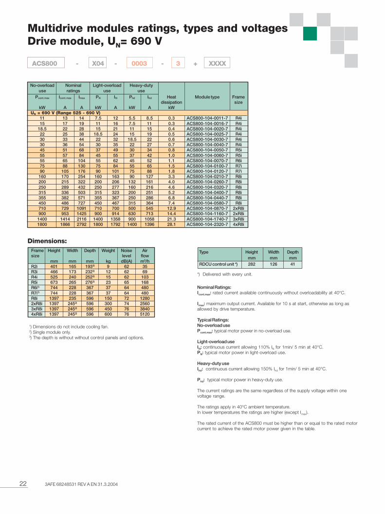
Multidrive modules ratings, types and voltagesDrive module, UN= 690 V
Type Height Width Depthmm mm mm
RDCU control unit *) 282 126 41
Frame Height Width Depth Weight Noise Airsize level flow
mm mm mm kg dB(A) m3/hR2i 401 165 1933) 9 62 35R3i 466 173 2323) 12 62 69R4i 525 240 2523) 15 62 103R5i 673 265 2763) 23 65 168R6i1) 744 228 367 37 64 480R7i1) 744 228 367 37 64 480R8i 1397 235 596 150 72 12802xR8i 1397 2452) 596 300 74 25603xR8i 1397 2452) 596 450 76 38404xR8i 1397 2452) 596 600 76 5120
1) Dimensions do not include cooling fan.2) Single module only.3) The depth is without without control panels and options.
Dimensions:
Nominal Ratings:Icont.max: rated current available continuously without overloadability at 40°C.
Imax: maximum output current. Available for 10 s at start, otherwise as long asallowed by drive temperature.
Typical Ratings:No-overload usePcont.max: typical motor power in no-overload use.
Light-overload useIN: continuous current allowing 110% IN for 1min/ 5 min at 40°C.PN: typical motor power in light-overload use.
Heavy-duty useIhd: continuous current allowing 150% Ihd for 1min/ 5 min at 40°C.
Phd: typical motor power in heavy-duty use.
The current ratings are the same regardless of the supply voltage within onevoltage range.
The ratings apply in 40°C ambient temperature.In lower temperatures the ratings are higher (except Imax).
The rated current of the ACS800 must be higher than or equal to the rated motorcurrent to achieve the rated motor power given in the table.
*) Delivered with every unit.
Pcont. max Icont. max Imax PN IN Phd Ihd Heat Module type Framedissipation size
kW A A kW A kW A kW UN = 690 V (Range 525 - 690 V)
11 13 14 7.5 12 5.5 8.5 0.3 ACS800-104-0011-7 R4i15 17 19 11 16 7.5 11 0.3 ACS800-104-0016-7 R4i
18.5 22 28 15 21 11 15 0.4 ACS800-104-0020-7 R4i22 25 38 18.5 24 15 19 0.5 ACS800-104-0025-7 R4i30 33 44 22 32 18.5 22 0.6 ACS800-104-0030-7 R4i30 36 54 30 35 22 27 0.7 ACS800-104-0040-7 R4i45 51 68 37 49 30 34 0.8 ACS800-104-0050-7 R5i55 57 84 45 55 37 42 1.0 ACS800-104-0060-7 R5i55 65 104 55 62 45 52 1.1 ACS800-104-0070-7 R6i75 88 130 75 84 55 65 1.5 ACS800-104-0100-7 R7i90 105 176 90 101 75 88 1.8 ACS800-104-0120-7 R7i
160 170 254 160 163 90 127 3.3 ACS800-104-0210-7 R8i200 215 322 200 206 132 161 4.0 ACS800-104-0260-7 R8i250 289 432 250 277 160 216 4.6 ACS800-104-0320-7 R8i315 336 503 315 323 200 251 5.2 ACS800-104-0400-7 R8i355 382 571 355 367 250 286 6.8 ACS800-104-0440-7 R8i450 486 727 450 467 315 364 7.4 ACS800-104-0580-7 R8i710 729 1091 710 700 500 545 12.9 ACS800-104-0870-7 2xR8i900 953 1425 900 914 630 713 14.4 ACS800-104-1160-7 2xR8i
1400 1414 2116 1400 1358 900 1058 21.3 ACS800-104-1740-7 3xR8i1800 1866 2792 1800 1792 1400 1396 28.1 ACS800-104-2320-7 4xR8i
Nominalratings
No-overloaduse
Light-overloaduse
Heavy-dutyuse
ACS800 - X04 - 0003 - 3 + XXXX

233AFE 68248531 REV A EN 31.3.2004
Multidrive modules ratings, types and voltagesSupply module, UN= 690 V
1) R6i, R7i dimensions do not include cooling fan.2) Single module only.3) Cable connections need additional space (about 200 mm)
behind the module.4) Supply modules + filters.5) Supply modules + choke.
Dimensions:Frame Height Width Depth Weight Noise Airsize level flow
mm mm mm kg dB(A) m3/hIGBT supply unit (ISU)R6i1) 744 228 367 37 654) 480R7i1) 744 228 367 37 654) 480R8i 1397 245 596 150 724) 12802xR8i 1397 2452) 596 300 744) 25603xR8i 1397 2452) 596 450 764) 76804xR8i 1397 2452) 596 600 764) 5120LCL-filter for IGBT supply unit (ISU)ISU_LCL_XR7 810 304 292 72 - 480ALCL-1X-X 1397 240 499 180 - 400ALCL-2X-X 1397 240 573 305 - 12806-pulse diode (DSU)D3 1480 234 4003) 130 65 720D4 1480 234 4003) 180 65 7202XD4 1480 2342) 4003) 360 67 14403XD4 1480 2342) 4003) 540 68 21604XD4 1480 2342) 4003) 720 69 28805XD4 1480 2342) 4003) 900 70 3600
Frame Height Width Depth Weight Noise Airsize level flow
mm mm mm kg dB(A) m3/h6-pulse regenerative (TSU)2XB4 1808 3402) 430 1102) 725) 20002XB5 1808 4202) 430 1502) 755) 3400DC chokes for 6-pulse regenerative (TSU)choke B4 771 348 449 110 - 600choke B5 991 348 449 150 - 70012-pulse diode (DSU)D4 1480 234 4003) 180 65 7202XD4 1480 2342) 4003) 360 67 14403XD4 1480 2342) 4003) 540 68 21604XD4 1480 2342) 4003) 720 69 28805XD4 1480 2342) 4003) 900 70 3600
Nominal ratingsNo-overloaduse
Light-overloaduse
Heavy-dutyuse
Pcont. max Icont. max Icont. max Imax SN PN IN Phd Ihd Heat Module type Framedissipation size
kW (DC) A (AC) A (DC) A (DC) kVA kW (DC) A (DC) kW (DC) A (DC) kWUN = 690 V (Range 525 - 690 V)IGBT supply module (ISU)
77 65 79 118 78 74 76 58 59 2.1 ACS800-104-0070-7 R6i + ISU_LCL_6R7104 88 107 160 105 100 102 78 80 3 ACS800-104-0100-7 R7i + ISU_LCL_6R7124 105 127 190 125 119 122 93 95 3.6 ACS800-104-0120-7 R7i + ISU_LCL_6R7213 180 218 327 215 204 210 159 163 8.3 ACS800-104-0260-7 R8i + ALCL-12-7296 250 303 453 299 284 291 221 227 9.4 ACS800-104-0400-7 R8i + ALCL-13-7355 300 364 544 359 341 349 266 272 13.3 ACS800-104-0440-7 R8i + ALCL-14-7473 400 485 726 478 454 466 354 363 14.6 ACS800-104-0560-7 R8i + ALCL-15-7710 600 727 1088 717 682 698 531 544 26.6 ACS800-104-0870-7 2xR8i + ALCL-24-7928 784 951 1422 937 890 913 694 711 28.5 ACS800-104-1160-7 2xR8i + ALCL-25-7
1377 1164 1411 2111 1391 1322 1355 1030 1056 42.3 ACS800-104-1740-7 3xR8i + 2xALCL-24-51817 1536 1862 2786 1836 1745 1788 1359 1393 55.7 ACS800-104-2320-7 4xR8i + 2xALCL-25-7
6-pulse diode (DSU)316 286 350 462 341 303 335 253 280 1.5 ACS800-304-0320-7 D3452 408 500 700 488 434 480 361 400 2.4 ACS800-304-0450-7 D3632 571 700 924 683 605 670 506 560 3.8 ACS800-704-0640-7 D4904 816 1000 1400 976 867 960 723 800 5 ACS800-704-0910-7 D4
1265 1143 1400 1848 1366 1211 1340 1012 1120 7.6 ACS800-704-1370-7 2xD41681 1518 1860 2604 1815 1617 1790 1346 1490 10 ACS800-704-1810-7 2xD42521 2278 2790 3906 2722 2426 2685 2015 2230 15 ACS800-704-2720-7 3xD43361 3037 3720 5208 3629 3235 3580 2693 2980 20 ACS800-704-3630-7 4xD44202 3796 4650 6510 4537 4043 4475 3361 3720 25 ACS800-704-4540-7 5xD4
6-pulse regenerative (TSU)784 711 871 1411 850 438 836 472 523 6.3 ACS800-404-0850-7 2xB4 + choke
1292 1171 1435 2325 1400 722 1378 778 861 10.2 ACS800-404-1400-7 2xB4 + choke2399 2176 2664 4316 2600 1340 2557 1444 1598 16.5 ACS800-404-2600-7 2xB5 + choke3152 2858 3500 5670 3415 1760 3360 1897 2100 20.8 ACS800-404-3600-7 2xB5 + choke
12-pulse diode (DSU)632 571 700 924 683 605 670 506 560 3.8 ACS800-704-0640-7 D4904 816 1000 1400 976 867 960 723 800 5 ACS800-704-0910-7 D4
1265 1143 1400 1848 1366 1211 1340 1012 1120 7.6 ACS800-704-1370-7 2xD41681 1518 1860 2604 1815 1617 1790 1346 1490 10 ACS800-704-1810-7 2xD42521 2278 2790 3906 2722 2426 2685 2015 2230 15 ACS800-704-2720-7 3xD43361 3037 3720 5208 3629 3235 3580 2693 2980 20 ACS800-704-3630-7 4xD44202 3796 4650 6510 4537 4043 4475 3361 3720 25 ACS800-704-4540-7 5xD4
Nominal Ratings:Icont.max: rated currentavailable continuouslywithout overloadability at40°C.
Imax: maximum outputcurrent.
Typical Ratings:No-overload usePcont.max: power in no-overload use.
Light-overload useIN: continuous currentallowing 110% IN for 1min/5 min at 40°C.PN: power in light-overload use.Heavy-duty useIhd: continuous currentallowing 150% Ihd for 1min/5 min at 40°C.
Phd: power in heavy-dutyuse.
The current ratings are thesame regardless of thesupply voltage within onevoltage range.
The ratings apply in 40°Cambient temperature. Inlower temperatures theratings are higher (exceptImax).
ACS800 - X04 - 0003 - 3 + XXXX
24 3AFE 68248531 REV A EN 31.3.2004
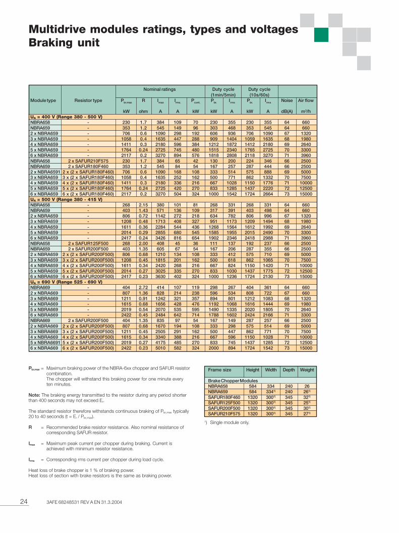
Multidrive modules ratings, types and voltagesBraking unit
Pbr,max = Maximum braking power of the NBRA-6xx chopper and SAFUR resistorcombination.The chopper will withstand this braking power for one minute everyten minutes.
Note: The braking energy transmitted to the resistor during any period shorterthan 400 seconds may not exceed Er.
The standard resistor therefore withstands continuous braking of Pbr,max typically20 to 40 seconds (t = Er / Pbr,max).
R = Recommended brake resistor resistance. Also nominal resistance ofcorresponding SAFUR resistor.
Imax = Maximum peak current per chopper during braking. Current isachieved with minimum resistor resistance.
Irms = Corresponding rms current per chopper during load cycle.
Heat loss of brake chopper is 1 % of braking power.Heat loss of section with brake resistors is the same as braking power.
Nominal ratings Duty cycle Duty cycle(1min/5min) (10s/60s)
Module type Resistor type Pbr.max R Imax Irms. Pcont. Pbr. Irms Pbr. Irms Noise Air flow
kW ohm A A kW kW A kW A dB(A) m3/hUN = 400 V (Range 380 - 500 V)NBRA658 - 230 1.7 384 109 70 230 355 230 355 64 660NBRA659 - 353 1.2 545 149 96 303 468 353 545 64 6602 x NBRA659 - 706 0.6 1090 298 192 606 936 706 1090 67 13203 x NBRA659 - 1058 0.4 1635 447 288 909 1404 1059 1635 68 19804 x NBRA659 - 1411 0.3 2180 596 384 1212 1872 1412 2180 69 26405 x NBRA659 - 1764 0.24 2725 745 480 1515 2340 1765 2725 70 33006 x NBRA659 - 2117 0.2 3270 894 576 1818 2808 2118 3270 71 3960NBRA658 2 x SAFUR210F575 230 1.7 384 65 42 130 200 224 346 66 2500NBRA659 2 x SAFUR180F460 353 1.2 545 84 54 167 257 287 444 66 25002 x NBRA6591 2 x (2 x SAFUR180F460) 706 0.6 1090 168 108 333 514 575 888 69 50003 x NBRA659 3 x (2 x SAFUR180F460) 1058 0.4 1635 252 162 500 771 862 1332 70 75004 x NBRA659 4 x (2 x SAFUR180F460) 1411 0.3 2180 336 216 667 1028 1150 1776 71 100005 x NBRA659 5 x (2 x SAFUR180F460) 1764 0.24 2725 420 270 833 1285 1437 2220 72 125006 x NBRA659 6 x (2 x SAFUR180F460) 2117 0.2 3270 504 324 1000 1542 1724 2664 73 15000UN = 500 V (Range 380 - 415 V)NBRA658 - 268 2.15 380 101 81 268 331 268 331 64 660NBRA659 - 403 1.43 571 136 109 317 391 403 498 64 6602 x NBRA659 - 806 0.72 1142 272 218 634 782 806 996 67 13203 x NBRA659 - 1208 0.48 1713 408 327 951 1173 1209 1494 68 19804 x NBRA659 - 1611 0.36 2284 544 436 1268 1564 1612 1992 69 26405 x NBRA659 - 2014 0.29 2855 680 545 1585 1955 2015 2490 70 33006 x NBRA659 - 2417 0.24 3426 816 654 1902 2346 2418 2988 71 3960NBRA658 2 x SAFUR125F500 268 2.00 408 45 36 111 137 192 237 66 2500NBRA659 2 x SAFUR200F500 403 1.35 605 67 54 167 206 287 355 66 25002 x NBRA659 2 x (2 x SAFUR200F500) 806 0.68 1210 134 108 333 412 575 710 69 50003 x NBRA659 3 x (2 x SAFUR200F500) 1208 0.45 1815 201 162 500 618 862 1065 70 75004 x NBRA659 4 x (2 x SAFUR200F500) 1611 0.34 2420 268 216 667 824 1150 1420 71 100005 x NBRA659 5 x (2 x SAFUR200F500) 2014 0.27 3025 335 270 833 1030 1437 1775 72 125006 x NBRA659 6 x (2 x SAFUR200F500) 2417 0.23 3630 402 324 1000 1236 1724 2130 73 15000UN = 690 V (Range 525 - 690 V)NBRA669 - 404 2.72 414 107 119 298 267 404 361 64 6602 x NBRA669 - 807 1.36 828 214 238 596 534 808 722 67 6603 x NBRA669 - 1211 0.91 1242 321 357 894 801 1212 1083 68 13204 x NBRA669 - 1615 0.68 1656 428 476 1192 1068 1616 1444 69 19805 x NBRA669 - 2019 0.54 2070 535 595 1490 1335 2020 1805 70 26406 x NBRA669 - 2422 0.45 2484 642 714 1788 1602 2424 2166 71 3300NBRA669 2 x SAFUR200F500 404 1.35 835 97 54 167 149 287 257 66 25002 x NBRA669 2 x (2 x SAFUR200F500) 807 0.68 1670 194 108 333 298 575 514 69 50003 x NBRA669 3 x (2 x SAFUR200F500) 1211 0.45 2505 291 162 500 447 862 771 70 75004 x NBRA669 4 x (2 x SAFUR200F500) 1615 0.34 3340 388 216 667 596 1150 1028 71 100005 x NBRA6691 5 x (2 x SAFUR200F500) 2019 0.27 4175 485 270 833 745 1437 1285 72 125006 x NBRA669 6 x (2 x SAFUR200F500) 2422 0.23 5010 582 324 2000 894 1724 1542 73 15000
Frame size Height Width Depth Weight
Brake Chopper ModulesNBRA658 584 334 240 26NBRA659 584 3341) 240 261)
SAFUR180F460 1320 3001) 345 321)
SAFUR125F500 1320 3001) 345 251)
SAFUR200F500 1320 3001) 345 301)
SAFUR210F575 1320 3001) 345 271)
1) Single module only.
253AFE 68248531 REV A EN 31.3.2004
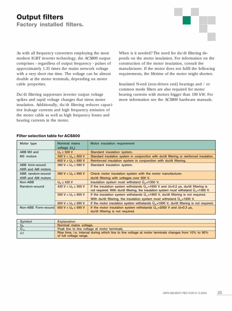
Output filtersFactory installed filters.
As with all frequency converters employing the mostmodern IGBT inverter technology, the ACS800 outputcomprises - regardless of output frequency - pulses ofapproximately 1.35 times the mains network voltagewith a very short rise time. The voltage can be almostdouble at the motor terminals, depending on motorcable properties.
Du/dt filtering suppresses inverter output voltagespikes and rapid voltage changes that stress motorinsulation. Additionally, du/dt filtering reduces capaci-tive leakage currents and high frequency emission ofthe motor cable as well as high frequency losses andbearing currents in the motor.
Motor type Nominal mains Motor insulation requirementvoltage (UN)
ABB M2 and UN ≤ 500 V Standard insulation system.M3 motors 500 V < UN ≤ 600 V Standard insulation system in conjunction with du/dt filtering or reinforced insulation.
600 V < UN ≤ 690 V Reinforced insulation system in conjunction with du/dt filtering.ABB form-wound 380 V < UN ≤ 690 V Standard insulation system.HXR and AM motorsABB random-wound 380 V < UN ≤ 690 V Check motor insulation system with the motor manufacturer.HXR and AM motors du/dt filtering with voltages over 500 V.Non-ABB UN ≤ 420 V Insulation system must withstand ÛLL=1300 V.Random-wound 420 V < UN ≤ 500 V If the insulation system withstands ÛLL=1600 V and ∆t=0.2 µs, du/dt filtering is
not required. With du/dt filtering, the insulation system must withstand ÛLL=1300 V.500 V < UN ≤ 600 V If the insulation system withstands ÛLL=1800 V, du/dt filtering is not required.
With du/dt filtering, the insulation system must withstand ÛLL=1600 V.600 V < UN ≤ 690 V If the motor insulation system withstands ÛLL=1800 V, du/dt filtering is not required.
Non-ABB Form-wound 600 V < UN ≤ 690 V If the motor insulation system withstands ÛLL=2000 V and ∆t=0.3 µs,du/dt filtering is not required.
ExplanationNominal mains voltage.Peak line to line voltage at motor terminals.Rise time, i.e. interval during which line to line voltage at motor terminals changes from 10% to 90%of full voltage range.
Filter selection table for ACS800
When is it needed? The need for du/dt filtering de-pends on the motor insulation. For information on theconstruction of the motor insulation, consult themanufacturer. If the motor does not fulfil the followingrequirements, the lifetime of the motor might shorten.
Insulated N-end (non-driven end) bearings and / orcommon mode filters are also required for motorbearing currents with motors bigger than 100 kW. Formore information see the ACS800 hardware manuals.
SymbolUN
Û LL
∆ t
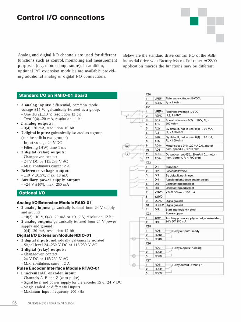
26 3AFE 68248531 REV A EN 31.3.2004
Analog and digital I/O channels are used for differentfunctions such as control, monitoring and measurementpurposes (e.g. motor temperature). In addition,optional I/O extension modules are available provid-ing additional analog or digital I/O connections.
Control I/O connections
Standard I/O on RMIO-01 Board
• 3 analog inputs: differential, common modevoltage ±15 V, galvanically isolated as a group.- One ±0(2)...10 V, resolution 12 bit- Two 0(4)...20 mA, resolution 11 bit
• 2 analog outputs:- 0(4)...20 mA, resolution 10 bit
• 7 digital inputs: galvanically isolated as a group(can be split in two groups)- Input voltage 24 V DC- Filtering (HW) time 1 ms
• 3 digital (relay) outputs:- Changeover contact- 24 V DC or 115/230 V AC- Max. continious current 2 A
• Reference voltage output:- ±10 V ±0.5%, max. 10 mA
• Auxiliary power supply output:- +24 V ±10%, max. 250 mA
Optional I/O
Analog I/O Extension Module RAIO-01• 2 analog inputs: galvanically isolated from 24 V supply
and ground- ±0(2)...10 V, 0(4)...20 mA or ±0...2 V, resolution 12 bit
• 2 analog outputs: galvanically isolated from 24 V powersupply and ground- 0(4)...20 mA, resolution 12 bit
Digital I/O Extension Module RDIO-01• 3 digital inputs: individually galvanically isolated
- Signal level 24...250 V DC or 115/230 V AC• 2 digital (relay) outputs:
- Changeover contact- 24 V DC or 115/230 V AC- Max. continious current 2 A
Pulse Encoder Interface Module RTAC-01• 1 incremental encoder input:
- Channels A, B and Z (zero pulse)- Signal level and power supply for the encoder 15 or 24 V DC- Single ended or differential inputs- Maximum input frequency 200 kHz
Below are the standard drive control I/O of the ABBindustrial drive with Factory Macro. For other ACS800application macros the functions may be different.
Reference voltage -10 VDC,
RL > 1 kohm
Reference voltage 10 VDC,RL > 1 kohm
Speed reference 0(2) ... 10 V, Rin >200 kohm
By default, not in use. 0(4) ... 20 mA,Rin = 100 ohm
By default, not in use. 0(4) ... 20 mA,Rin = 100 ohm
Motor speed 0(4)...20 mA = 0...motornom. speed, RL < 700 ohm
Output current 0(4)...20 mA = 0...motornom. current, RL < 700 ohm
Stop/StartForward/Reverse
By default, not in use.
Acceleration & deceleration selectConstant speed select
Constant speed select
+24 V DC max. 100 mA
Digital groundDigital ground
Start interlock (0 = stop)Power supply
Auxiliary power supply output, non-isolated,24 V DC 250 mA
Relay output 1: ready
Relay output 2: running
Relay output 3: fault (-1)
^
^
VREF-
AGND
VREF+
AGND
AI1+
AI1-
AI2+
AI2-
AI3+
AI3-
AO1+
AO1-
AO2+
AO2-
DI1
DI2
DI3
DI4
DI5
DI6
+24VD
+24VD
DGND1
DGND2
DIIL
+24V
GND
RO11
RO12
RO13
RO21
RO22
RO23
RO31
RO32
RO33
X20
1
2
X21
1
2
3
4
5
6
7
8
9
10
11
12
X22
1
2
3
4
5
6
7
8
9
10
11
X23
1
2
X25
1
2
3
X26
1
2
3
X27
1
2
3
A
rpm
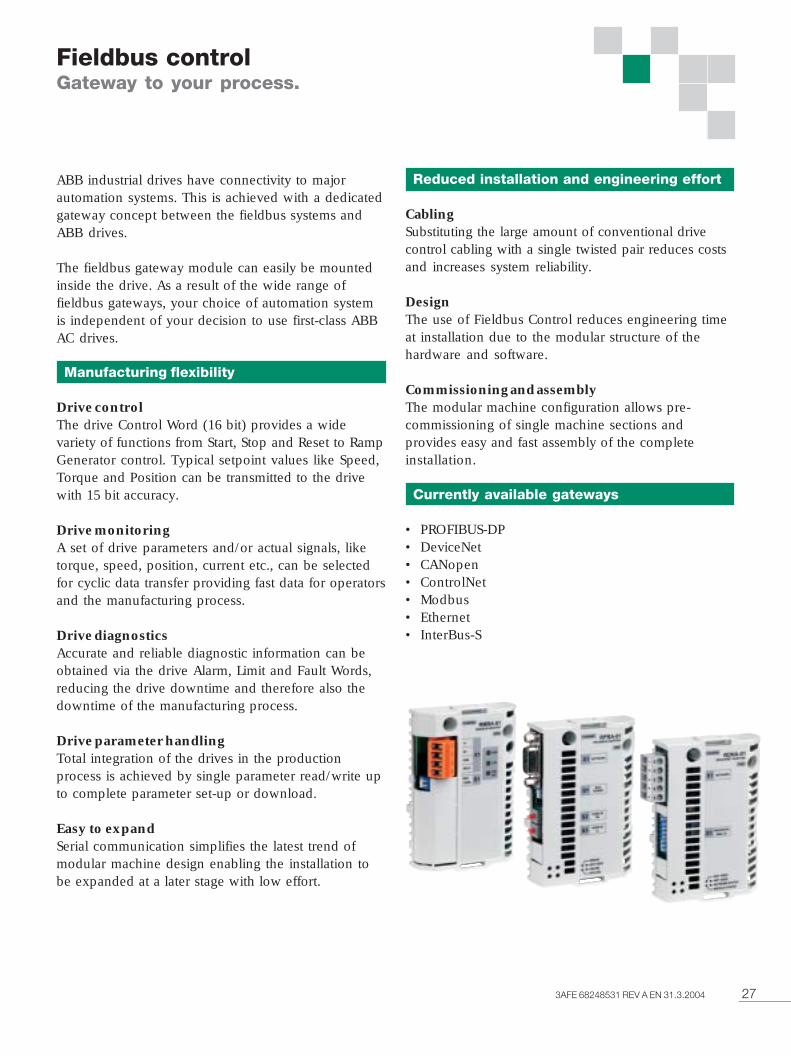
273AFE 68248531 REV A EN 31.3.2004
Fieldbus controlGateway to your process.
ABB industrial drives have connectivity to majorautomation systems. This is achieved with a dedicatedgateway concept between the fieldbus systems andABB drives.
The fieldbus gateway module can easily be mountedinside the drive. As a result of the wide range offieldbus gateways, your choice of automation systemis independent of your decision to use first-class ABBAC drives.
Manufacturing flexibility
Drive controlThe drive Control Word (16 bit) provides a widevariety of functions from Start, Stop and Reset to RampGenerator control. Typical setpoint values like Speed,Torque and Position can be transmitted to the drivewith 15 bit accuracy.
Drive monitoringA set of drive parameters and/or actual signals, liketorque, speed, position, current etc., can be selectedfor cyclic data transfer providing fast data for operatorsand the manufacturing process.
Drive diagnosticsAccurate and reliable diagnostic information can beobtained via the drive Alarm, Limit and Fault Words,reducing the drive downtime and therefore also thedowntime of the manufacturing process.
Drive parameter handlingTotal integration of the drives in the productionprocess is achieved by single parameter read/write upto complete parameter set-up or download.
Easy to expandSerial communication simplifies the latest trend ofmodular machine design enabling the installation tobe expanded at a later stage with low effort.
Reduced installation and engineering effort
CablingSubstituting the large amount of conventional drivecontrol cabling with a single twisted pair reduces costsand increases system reliability.
DesignThe use of Fieldbus Control reduces engineering timeat installation due to the modular structure of thehardware and software.
Commissioning and assemblyThe modular machine configuration allows pre-commissioning of single machine sections andprovides easy and fast assembly of the completeinstallation.
Currently available gateways
• PROFIBUS-DP• DeviceNet• CANopen• ControlNet• Modbus• Ethernet• InterBus-S
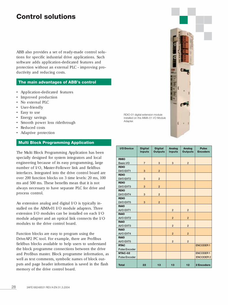
28 3AFE 68248531 REV A EN 31.3.2004
ABB also provides a set of ready-made control solu-tions for specific industrial drive applications. Suchsoftware adds application-dedicated features andprotection without an external PLC - improving pro-ductivity and reducing costs.
The main advantages of ABB’s controlsolutions:
• Application-dedicated features• Improved production• No external PLC• User-friendly• Easy to use• Energy savings• Smooth power loss ridethrough• Reduced costs• Adaptive protection
Multi Block Programming Application
The Multi Block Programming Application has beenspecially designed for system integrators and localengineering because of its easy programming, largenumber of I/O, Master-Follower link and fieldbusinterfaces. Integrated into the drive control board areover 200 function blocks on 3 time levels: 20 ms, 100ms and 500 ms. These benefits mean that it is notalways necessary to have separate PLC for drive andprocess control.
An extension analog and digital I/O is typically in-stalled on the AIMA-01 I/O module adapters. Threeextension I/O modules can be installed on each I/Omodule adapter and an optical link connects the I/Omodules to the drive control board.
Function blocks are easy to program using theDriveAP2 PC tool. For example, there are Profibusfieldbus blocks available to help users to understandthe block programme connections between the driveand Profibus master. Block programme information, aswell as text comments, symbolic names of block out-puts and page header information is saved in the flashmemory of the drive control board.
RMIOBasic I/O 7 3 3 2RDIODI/O EXT1 3 2RDIODI/O EXT2 3 2RDIODI/O EXT3 3 2RDIODI/O EXT4 3 2RDIODI/O EXT5 3 2RAIOAI/O EXT1 2 2RAIOAI/O EXT2 2 2RAIOAI/O EXT3 2 2RAIOAI/O EXT4 2 2RAIOAI/O EXT5 2 2RTAC ENCODER 1
Pulse EncoderNTAC-02 ENCODER 1
Pulse Encoder ENCODER 2
Total 22 13 13 12 2 Encoders
I/O Device DigitalInputs
DigitalOutputs
AnalogInputs
AnalogOutputs
PulseEncoders
Control solutions
RDIO-01 digital extension moduleinstalled on the AIMA-01 I/O ModuleAdapter.
293AFE 68248531 REV A EN 31.3.2004
System Application
The software is targeted for multi-motor machinesproducing or processing metal, paper, plastics, textile,rubber, cement, and for numerous other demandingapplications. The basic control modes are speedcontrol and torque control. Fast communication withthe overriding controller can exchange operative data(references, command words) and support data(configuration data, diagnostics). Proprietary (DDCS,Drive bus) and generic (PROFIBUS, InterBus,DeviceNet) protocols enable linking of drives tocontrollers, PLC and PCs.
The major features are the soft changeover betweenthe speed and torque control modes, drooping inspeed control, fast Master-Follower link between twoor more drives and inertia compensation.
Benefits with System Application• Extended communication capability, 24 data words
available for both directions between the drive andoverriding system.
• Torsional oscillation damping function to dampmechanical oscillations.
• PT100 or PTC measurement (max. 2 motors)• Thermal model for motor cable protection• Motor fan control with diagnostics• Freely programmable outputs: analog (max. 4) and
digital (max. 5)• Speed control gain as a function of output on low
speed or as a function of motor frequency
Centrifuge Control
Practical programmable sequences for conventionalcentrifuges. Integrated Decanter Control for the accu-rate speed difference control of two shafts, wheredirect communication via the fibre optic link betweenbowl and scroll is used.
Extruder Control
High starting torque, accurate speed/torque controlwithout an encoder for demanding extruder applica-tions. The extruder screw and other delicate mechanicalparts can be protected against overload.
Pump and Fan Control
Better flow control and cost savings for up to 5 parallelmotors in various industrial pump and fan applications.Featuring many important PFC functions, includingsleep/ wake up and autochange etc.
Crane Drive Control
Cost-effective crane drive control with optimal opera-tional safety and outstanding performance alreadybuilt in.
• Easy installation and start-up reduces the totalproject costs
• Ready to use with proven modular cranefunctionality
• Accurate and fast torque response increases theoperational productivity
• Smooth crane operation reduces maintenance anddamage costs
• Available as single drive and multi-drive withdynamic and regenerative braking
Standard ready-to-use crane drive solution with optimaloperational safety and outstanding crane drive perfor-mance.
Master/Follower Control
Reliable control via the fibre optic link of severaldrives when motor shafts are coupled together.Thanks to Master/Follower function the load can beevenly distributed between the drives.
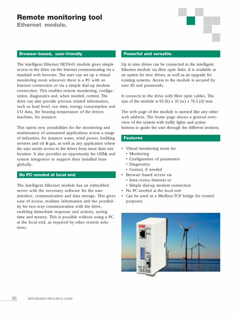
30 3AFE 68248531 REV A EN 31.3.2004
Remote monitoring toolEthernet module.
Browser-based, user-friendly
The intelligent Ethernet NETA-01 module gives simpleaccess to the drive via the Internet communicating via astandard web browser. The user can set up a virtualmonitoring room wherever there is a PC with anInternet connection or via a simple dial-up modemconnection. This enables remote monitoring, configu-ration, diagnostics and, when needed, control. Thedrive can also provide process related information,such as load level, run time, energy consumption andI/O data, the bearing temperature of the drivenmachine, for instance.
This opens new possibilities for the monitoring andmaintenance of unmanned applications across a rangeof industries, for instance water, wind power, buildingservices and oil & gas, as well as any application wherethe user needs access to the drives from more than onelocation. It also provides an opportunity for OEMs andsystem integrators to support their installed baseglobally.
No PC needed at local end
The intelligent Ethernet module has an embeddedserver with the necessary software for the userinterface, communication and data storage. This givesease of access, realtime information and the possibil-ity for two-way communication with the drive,enabling immediate response and actions, savingtime and money. This is possible without using a PCat the local end, as required by other remote solu-tions.
Powerful and versatile
Up to nine drives can be connected to the intelligentEthernet module via fibre optic links. It is available asan option for new drives, as well as an upgrade forexisting systems. Access to the module is secured byuser ID and passwords.
It connects to the drive with fibre optic cables. Thesize of the module is 93 (h) x 35 (w) x 76.5 (d) mm.
The web page of the module is opened like any otherweb address. The home page shows a general over-view of the system with traffic lights and actionbuttons to guide the user through the different sections.
Features
• Virtual monitoring room for• Monitoring• Configuration of parameters• Diagnostics• Control, if needed
• Browser based access via• Intra-/extra-/Internet or• Simple dial-up modem connection
• No PC needed at the local end• Can be used as a Modbus/TCP bridge for control
purposes
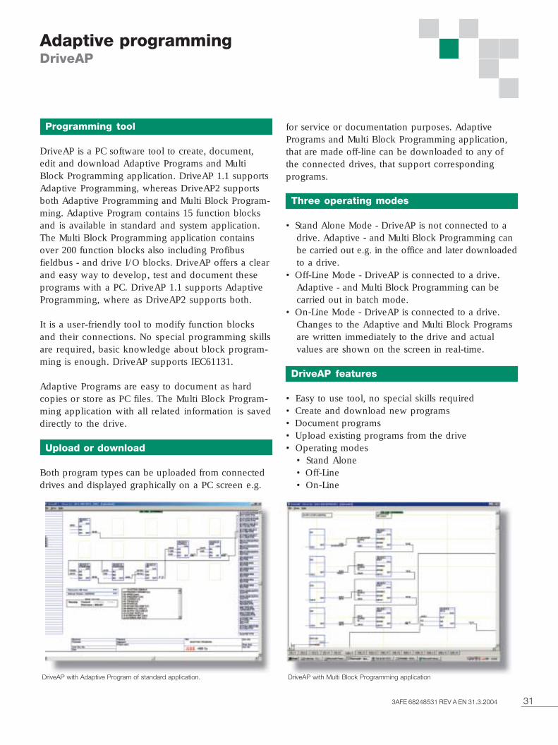
313AFE 68248531 REV A EN 31.3.2004
Programming tool
DriveAP is a PC software tool to create, document,edit and download Adaptive Programs and MultiBlock Programming application. DriveAP 1.1 supportsAdaptive Programming, whereas DriveAP2 supportsboth Adaptive Programming and Multi Block Program-ming. Adaptive Program contains 15 function blocksand is available in standard and system application.The Multi Block Programming application containsover 200 function blocks also including Profibusfieldbus - and drive I/O blocks. DriveAP offers a clearand easy way to develop, test and document theseprograms with a PC. DriveAP 1.1 supports AdaptiveProgramming, where as DriveAP2 supports both.
It is a user-friendly tool to modify function blocksand their connections. No special programming skillsare required, basic knowledge about block program-ming is enough. DriveAP supports IEC61131.
Adaptive Programs are easy to document as hardcopies or store as PC files. The Multi Block Program-ming application with all related information is saveddirectly to the drive.
Upload or download
Both program types can be uploaded from connecteddrives and displayed graphically on a PC screen e.g.
for service or documentation purposes. AdaptivePrograms and Multi Block Programming application,that are made off-line can be downloaded to any ofthe connected drives, that support correspondingprograms.
Three operating modes
• Stand Alone Mode - DriveAP is not connected to adrive. Adaptive - and Multi Block Programming canbe carried out e.g. in the office and later downloadedto a drive.
• Off-Line Mode - DriveAP is connected to a drive.Adaptive - and Multi Block Programming can becarried out in batch mode.
• On-Line Mode - DriveAP is connected to a drive.Changes to the Adaptive and Multi Block Programsare written immediately to the drive and actualvalues are shown on the screen in real-time.
DriveAP features
• Easy to use tool, no special skills required• Create and download new programs• Document programs• Upload existing programs from the drive• Operating modes
• Stand Alone• Off-Line• On-Line
Adaptive programmingDriveAP
DriveAP with Adaptive Program of standard application. DriveAP with Multi Block Programming application
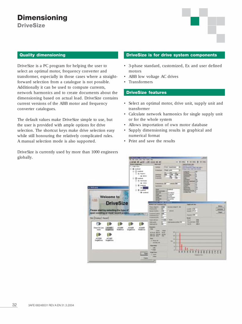
32 3AFE 68248531 REV A EN 31.3.2004
Quality dimensioning
DriveSize is a PC program for helping the user toselect an optimal motor, frequency converter andtransformer, especially in those cases where a straight-forward selection from a catalogue is not possible.Additionally it can be used to compute currents,network harmonics and to create documents about thedimensioning based on actual load. DriveSize containscurrent versions of the ABB motor and frequencyconverter catalogues.
The default values make DriveSize simple to use, butthe user is provided with ample options for driveselection. The shortcut keys make drive selection easywhile still honouring the relatively complicated rules.A manual selection mode is also supported.
DriveSize is currently used by more than 1000 engineersglobally.
DimensioningDriveSize
DriveSize is for drive system components
• 3-phase standard, customized, Ex and user definedmotors
• ABB low voltage AC drives• Transformers
DriveSize features
• Select an optimal motor, drive unit, supply unit andtransformer
• Calculate network harmonics for single supply unitor for the whole system
• Allows importation of own motor database• Supply dimensioning results in graphical and
numerical format• Print and save the results
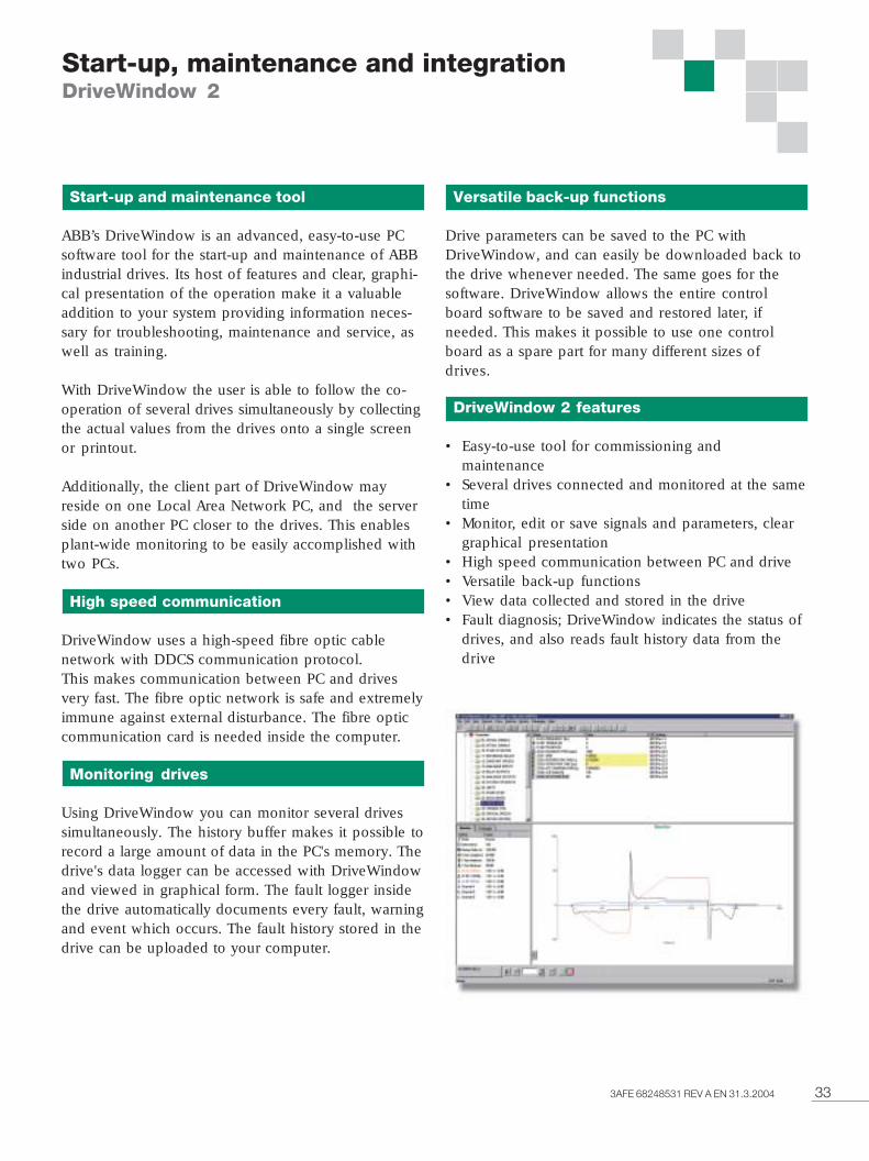
333AFE 68248531 REV A EN 31.3.2004
Start-up and maintenance tool
ABB’s DriveWindow is an advanced, easy-to-use PCsoftware tool for the start-up and maintenance of ABBindustrial drives. Its host of features and clear, graphi-cal presentation of the operation make it a valuableaddition to your system providing information neces-sary for troubleshooting, maintenance and service, aswell as training.
With DriveWindow the user is able to follow the co-operation of several drives simultaneously by collectingthe actual values from the drives onto a single screenor printout.
Additionally, the client part of DriveWindow mayreside on one Local Area Network PC, and the serverside on another PC closer to the drives. This enablesplant-wide monitoring to be easily accomplished withtwo PCs.
High speed communication
DriveWindow uses a high-speed fibre optic cablenetwork with DDCS communication protocol.This makes communication between PC and drivesvery fast. The fibre optic network is safe and extremelyimmune against external disturbance. The fibre opticcommunication card is needed inside the computer.
Monitoring drives
Using DriveWindow you can monitor several drivessimultaneously. The history buffer makes it possible torecord a large amount of data in the PC's memory. Thedrive's data logger can be accessed with DriveWindowand viewed in graphical form. The fault logger insidethe drive automatically documents every fault, warningand event which occurs. The fault history stored in thedrive can be uploaded to your computer.
Versatile back-up functions
Drive parameters can be saved to the PC withDriveWindow, and can easily be downloaded back tothe drive whenever needed. The same goes for thesoftware. DriveWindow allows the entire controlboard software to be saved and restored later, ifneeded. This makes it possible to use one controlboard as a spare part for many different sizes ofdrives.
DriveWindow 2 features
• Easy-to-use tool for commissioning andmaintenance
• Several drives connected and monitored at the sametime
• Monitor, edit or save signals and parameters, cleargraphical presentation
• High speed communication between PC and drive• Versatile back-up functions• View data collected and stored in the drive• Fault diagnosis; DriveWindow indicates the status of
drives, and also reads fault history data from thedrive
Start-up, maintenance and integrationDriveWindow 2
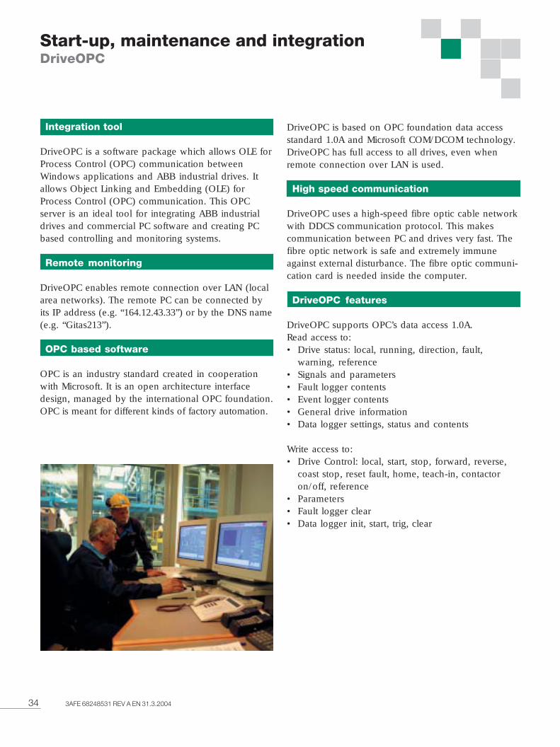
34 3AFE 68248531 REV A EN 31.3.2004
Integration tool
DriveOPC is a software package which allows OLE forProcess Control (OPC) communication betweenWindows applications and ABB industrial drives. Itallows Object Linking and Embedding (OLE) forProcess Control (OPC) communication. This OPCserver is an ideal tool for integrating ABB industrialdrives and commercial PC software and creating PCbased controlling and monitoring systems.
Remote monitoring
DriveOPC enables remote connection over LAN (localarea networks). The remote PC can be connected byits IP address (e.g. “164.12.43.33”) or by the DNS name(e.g. “Gitas213”).
OPC based software
OPC is an industry standard created in cooperationwith Microsoft. It is an open architecture interfacedesign, managed by the international OPC foundation.OPC is meant for different kinds of factory automation.
DriveOPC is based on OPC foundation data accessstandard 1.0A and Microsoft COM/DCOM technology.DriveOPC has full access to all drives, even whenremote connection over LAN is used.
High speed communication
DriveOPC uses a high-speed fibre optic cable networkwith DDCS communication protocol. This makescommunication between PC and drives very fast. Thefibre optic network is safe and extremely immuneagainst external disturbance. The fibre optic communi-cation card is needed inside the computer.
DriveOPC features
DriveOPC supports OPC’s data access 1.0A.Read access to:• Drive status: local, running, direction, fault,
warning, reference• Signals and parameters• Fault logger contents• Event logger contents• General drive information• Data logger settings, status and contents
Write access to:• Drive Control: local, start, stop, forward, reverse,
coast stop, reset fault, home, teach-in, contactoron/off, reference
• Parameters• Fault logger clear• Data logger init, start, trig, clear
Start-up, maintenance and integrationDriveOPC
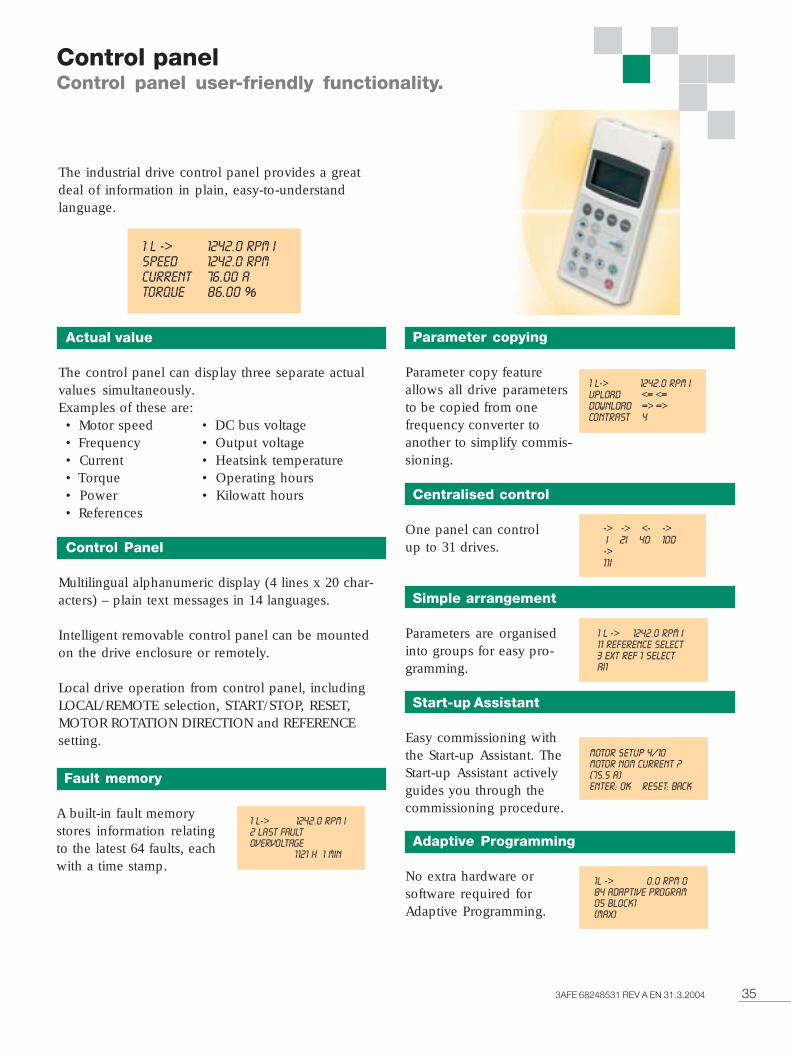
353AFE 68248531 REV A EN 31.3.2004
Control panelControl panel user-friendly functionality.
The industrial drive control panel provides a greatdeal of information in plain, easy-to-understandlanguage.
Actual value
The control panel can display three separate actualvalues simultaneously.Examples of these are:• Motor speed • DC bus voltage• Frequency • Output voltage• Current • Heatsink temperature• Torque • Operating hours• Power • Kilowatt hours• References
Control Panel
Multilingual alphanumeric display (4 lines x 20 char-acters) – plain text messages in 14 languages.
Intelligent removable control panel can be mountedon the drive enclosure or remotely.
Local drive operation from control panel, includingLOCAL/REMOTE selection, START/STOP, RESET,MOTOR ROTATION DIRECTION and REFERENCEsetting.
Fault memory
A built-in fault memorystores information relatingto the latest 64 faults, eachwith a time stamp.
Parameter copying
Parameter copy featureallows all drive parametersto be copied from onefrequency converter toanother to simplify commis-sioning.
Centralised control
One panel can controlup to 31 drives.
Simple arrangement
Parameters are organisedinto groups for easy pro-gramming.
Start-up Assistant
Easy commissioning withthe Start-up Assistant. TheStart-up Assistant activelyguides you through thecommissioning procedure.
Adaptive Programming
No extra hardware orsoftware required forAdaptive Programming.
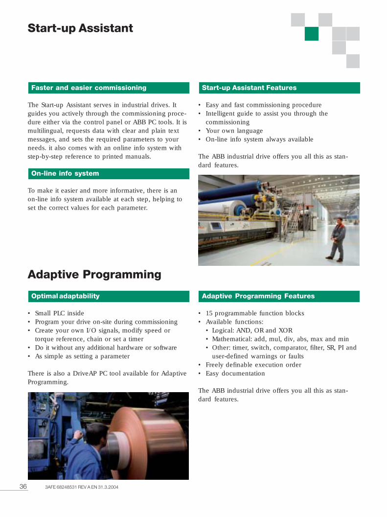
36 3AFE 68248531 REV A EN 31.3.2004
Adaptive Programming
Optimal adaptability
• Small PLC inside• Program your drive on-site during commissioning• Create your own I/O signals, modify speed or
torque reference, chain or set a timer• Do it without any additional hardware or software• As simple as setting a parameter
There is also a DriveAP PC tool available for AdaptiveProgramming.
Adaptive Programming Features
• 15 programmable function blocks• Available functions:
• Logical: AND, OR and XOR• Mathematical: add, mul, div, abs, max and min• Other: timer, switch, comparator, filter, SR, PI and
user-defined warnings or faults• Freely definable execution order• Easy documentation
The ABB industrial drive offers you all this as stan-dard features.
Start-up Assistant
Faster and easier commissioning
The Start-up Assistant serves in industrial drives. Itguides you actively through the commissioning proce-dure either via the control panel or ABB PC tools. It ismultilingual, requests data with clear and plain textmessages, and sets the required parameters to yourneeds. it also comes with an online info system withstep-by-step reference to printed manuals.
On-line info system
To make it easier and more informative, there is anon-line info system available at each step, helping toset the correct values for each parameter.
Start-up Assistant Features
• Easy and fast commissioning procedure• Intelligent guide to assist you through the
commissioning• Your own language• On-line info system always available
The ABB industrial drive offers you all this as stan-dard features.
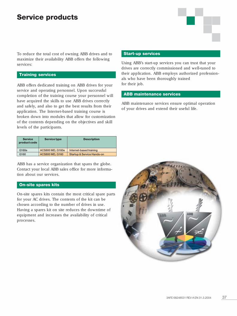
373AFE 68248531 REV A EN 31.3.2004
Service products
To reduce the total cost of owning ABB drives and tomaximize their availability ABB offers the followingservices:
Training services
ABB offers dedicated training on ABB drives for yourservice and operating personnel. Upon successfulcompletion of the training course your personnel willhave acquired the skills to use ABB drives correctlyand safely, and also to get the best results from theirapplication. The Internet-based training course isbroken down into modules that allow for customizationof the contents depending on the objectives and skilllevels of the participants.
ABB has a service organization that spans the globe.Contact your local ABB sales office for more informa-tion about our services.
On-site spares kits
On-site spares kits contain the most critical spare partsfor your AC drives. The contents of the kit can bechosen according to the number of drives in use.Having a spares kit on site reduces the downtime ofequipment and increases the availability of criticalprocesses.
Start-up services
Using ABB’s start-up services you can trust that yourdrives are correctly commissioned and well-tuned totheir application. ABB employs authorized profession-als who have been thoroughly trainedfor their job.
ABB maintenance services
ABB maintenance services ensure optimal operationof your drives and extend their useful life.
G160e ACS800 MD, G160e Internet-based trainingG160 ACS800 MD, G160 Startup & Service Hands-on
Serviceproduct code
Service type Description
38 3AFE 68248531 REV A EN 31.3.2004
ABB’s worldwide presence is built on strong localcompanies working together with the local distributorand channel partner network across borders to achievea uniform level of services for all our customers. Bycombining the experience and know-how gained inlocal and global markets, we ensure that ourcustomers in all industries can gain the full benefitfrom our products.
For further details about all our variable speed driveproducts and services please contact your nearest ABBoffice or visit the ABB website www.abb.com/motors&drives.
Contact and web informationwww.abb.com/motors&drives
Argentina (Valentin Alsina)Tel: +54 (0)114 229 5707Fax: +54 (0)114 229 5593
Australia (Victoria)Tel: 1800 222 435Tel: +61 3 8544 0000Fax: +61 3 8544 0004
Austria (Vienna)Tel: 0800 201 009Tel: +43 1 60109-0Fax: +43 1 60109-8312
Belarus (Minsk)Tel: +375 172 236 711Tel: +375 172 239 185Fax: +375 172 239 154
Belgium (Zaventem)Tel: +32 2 718 6313Fax: +32 2 718 6664
Bolivia (La Paz)Tel: +591 2 242 3636Fax: +591 2 242 3698
Bosnia Herzegovina (Tuzla)Tel: +387 35 255 097Fax: +387 35 255 098
Brazil (Sao Paulo)Tel: 0800 149 111Tel: +55 11 3688 9282Fax: +55 11 3684 1991
Bulgaria (Sofia)Tel: +359 2 981 4533Fax: +359 2 980 0846
Canada (Montreal)Tel: +1 514 215 3006Fax: +1 514 332 0609
Chile (Santiago)Tel: +56 2 471 4391Fax: +56 2 471 4399
China (Beijing)Tel: +86 10 8456 6688Fax: +86 10 8456 7636
Colombia (Bogota)Tel: +57 1 417 8000Fax: +57 1 413 4086
Croatia (Zagreb)Tel: +385 1 600 8550Fax: +385 1 239 5598
Czech Republic (Prague)Tel: +420 234 322 360Fax: +420 234 322 310
Denmark (Skovlunde)Tel: +45 44 504 345Fax: +45 44 504 365
Estonia (Tallinn)Tel: +372 6 711 800Fax: +372 6 711 810
Finland (Helsinki)Tel: +358 10 22 11Tel: +358 10 222 1999Fax: +358 10 222 2913
France (Champagne)Tel: +33 (0)810 020 000Fax: +33 (0)472 054 041
Germany (Lampertheim)Tel: 01805 123 580Tel: +49 (0)6206 503 503Fax: +49 (0)6206 503 600
Greece (Athens)Tel: +30 210 289 1900Fax: +30 210 289 1999
Hungary (Budapest)Tel: +36 1 443 2224Fax: +36 1 443 2144
India (Bangalore)Tel: +91 80 837 0416Fax: +91 80 839 9173
Indonesia (Jakarta)Tel: +62 21 590 9955Fax: +62 21 590 0115Fax: +62 21 590 0116
Ireland (Dublin)Tel: +353 1 405 7300Fax: +353 1 405 7312
Israel (Tirat Carmel)Tel: +972 4 858 1188Fax: +972 4 858 1199
Italy (Milano)Tel: +39 02 2414 3792Fax: +39 02 2414 3979
Latvia (Riga)Tel: +371 7 063 600Fax: +371 7 063 601
Lithuania (Vilnius)Tel: +370 5 273 8300Fax: +370 5 273 8333
Luxembourg (Leudelange)Tel: +352 493 116Fax: +352 492 859
Macedonia (Skopje)Tel: +389 2 118 010Fax: +389 2 118 774
Malaysia (Kuala Lumpur)Tel: +60 3 5628 4888Fax: +60 3 5631 2926
Mexico (Mexico City)Tel: +52 55 5328 1400Fax: +52 55 5328 1482/1439
The Netherlands (Rotterdam)Tel: +31 (0)10 407 8362Fax: +31 (0)10 407 8433
New Zealand (Auckland)Tel: +64 9 356 2170Fax: +64 9 357 0019
Norway (Oslo)Tel: +47 22 872 000Fax: +47 22 872 541
Peru (Lima)Tel: +51 1 561 0404Fax: +51 1 561 3040
Philippines (Metro Manila)Tel: +63 2 821 7777Fax: +63 2 823 0309Fax: +63 2 824 4637
Poland (Lodz)Tel: +48 42 613 4900Fax: +48 42 613 4901
Portugal (Amadora)Tel: +351 21 425 6239Fax: +351 21 425 6392
Romania (Bucarest)Tel: +40 21 310 4377Fax: +40 21 310 4383
Russia (Moscow)Tel: +7 095 960 22 00Fax: +7 095 913 96 95
Saudi-Arabia (Al Khobar)Tel: +966 (0)3 882 9394Fax: +966 (0)3 882 4603
Serbia and Montenegro(Belgrade)Tel: +381 11 324 4341Fax: +381 11 324 1623
SingaporeTel: +65 6776 5711Fax: +65 6778 0222
Slovakia (Banska Bystrica)Tel: +421 48 410 2324Fax: +421 48 410 2325
Slovenia (Ljubljana)Tel: +386 1 587 5482Fax: +386 1 587 5495
South Africa (Johannesburg)Tel: +27 11 617 2000Fax: +27 11 908 2061
South Korea (Seoul)Tel: +82 2 528 2794Fax: +82 2 528 2338
Spain (Barcelona)Tel: +34 (9)3 728 8700Fax: +34 (9)3 728 8743
Sweden (Västerås)Tel: +46 (0)21 32 93 00Fax: +46 (0)21 32 93 01
Switzerland (Zürich)Tel: +41 (0)58 586 0000Fax: +41 (0)58 586 0603
Taiwan (Taipei)Tel: +886 2 2577 6090Fax: +886 2 2577 9467Fax: +866 2 2577 9434
Thailand (Bangkok)Tel: +66 (0)2665 1000Fax: +66 (0)2665 1042
Turkey (Istanbul)Tel: +90 216 528 2200Fax: +90 216 365 2944
United Kingdom(Manchester)Tel: +44 (0)161 445 5555Fax: +44 (0)161 445 6066
Uruguay (Montevideo)Tel: +598 2 707 7300Tel: +598 2 707 7466
USA (New Berlin)Tel: +1 800 752 0696Tel: +1 262 785 3200Fax: +1 262 785 0397
Venezuela (Caracas)Tel: +58 212 203 1817Fax: +58 212 237 6270

393AFE 68248531 REV A EN 31.3.2004
Notes
Ad
agen
cy P
iirte
k O
y #1
1198
ABB OyDrivesP. O. Box 184FIN - 00381 HelsinkiFinlandTelephone +358 10 22 11Telefax +358 10 222 2681Internet http://www.abb.com/motors&drives
HA
NS
AP
RIN
T/X
XX
XX
/200
4
Cop
yrig
ht ©
AB
B O
y, 2
004
3A
FE 6
8248
531
RE
V A
EN
31.
3.20
04
Spe
cific
atio
ns s
ubje
ct to
cha
nge
with
out n
otic
e.Th
e In
dust
rialIT
wor
dmar
k an
d al
l abo
ve-m
entio
ned
prod
uct
nam
es in
the
form
Driv
eIT a
re r
egis
tere
d or
pen
ding
tra
dem
arks
of A
BB
.