Embed Size (px)
Citation preview

ACS800
Hardware ManualACS800-02 Drives (45 to 500 kW)ACS800-U2 Drives (60 to 600 HP)

ACS800 Single Drive Manuals
HARDWARE MANUALS (appropriate manual is included in the delivery)
ACS800-01/U1 Hardware Manual 0.55 to 110 kW (0.75 to 150 HP) 3AFE 64382101 (English)ACS800-02/U2 Hardware Manual 45 to 500 kW (60 to 600 HP) 3AFE 64567373 (English)ACS800-04/04M/U4 Hardware Manual 45 to 560 kW (60 to 600 HP) 3AFE 64671006 (English)ACS800-07/U7 Hardware Manual 45 to 560 kW (50 to 600 HP) 3AFE 64702165 (English)ACS800-07/U7 Dimensional Drawings 45 to 560 kW (50 to 600 HP) 3AFE 64775421 ACS800-07 Hardware Manual 500 to 2800 kW3AFE 64731165 (English)ACS800-17 Hardware Manual 75 to 1120 kW3AFE 64681338 (English)
• Safety instructions• Electrical installation planning• Mechanical and electrical installation• Motor control and I/O board (RMIO)• Maintenance• Technical data• Dimensional drawings• Resistor braking
FIRMWARE MANUALS, SUPPLEMENTS AND GUIDES (appropriate documents are included in the delivery)
Standard Application Program Firmware Manual 3AFE 64527592 (English)System Application Program Firmware Manual 3AFE 63700177 (English)Application Program Template Firmware Manual 3AFE 64616340 (English)Master/Follower 3AFE 64590430 (English)PFC Application Program Firmware Manual 3AFE 64649337 (English)Extruder Control Program Supplement 3AFE 64648543 (English)Centrifuge Control Program Supplement 3AFE 64667246 (English)Traverse Control Program Supplement 3AFE 64618334 (English)Crane Control Program Firmware Manual 3BSE 11179 (English)Adaptive Programming Application Guide 3AFE 64527274 (English)
OPTION MANUALS (delivered with optional equipment)
Fieldbus Adapters, I/O Extension Modules etc.

ACS800-02 Drives45 to 500 kW
ACS800-U2 Drives60 to 600 HP
Hardware Manual
3AFE 64567373 Rev C ENEFFECTIVE: 18.11.2003
� 2003 ABB Oy. All Rights Reserved.


5
Safety instructions
What this chapter containsThis chapter contains the safety instructions which you must follow when installing, operating and servicing the drive. If ignored, physical injury or death may follow, or damage may occur to the drive, the motor or driven equipment. Read the safety instructions before you work on the unit.
To which products this chapter appliesThis chapter applies to the ACS800-01/U1, the ACS800-02/U2 and the ACS800-04/U4.
Use of warnings and notesThere are two types of safety instructions throughout this manual: warnings and notes. Warnings caution you about conditions which can result in serious injury or death and/or damage to the equipment. They also tell you how to avoid the danger. Notes draw attention to a particular condition or fact, or give information on a subject. The warning symbols are used as follows:
Dangerous voltage warning warns of high voltage which can cause physical injury and/or damage to the equipment.
General warning warns about conditions, other than those caused by electricity, which can result in physical injury and/or damage to the equipment.
Electrostatic discharge warning warns of electrostatic discharge which can damage the equipment.
Safety instructions

6
Installation and maintenance workThese warnings are intended for all who work on the drive, motor cable or motor. Ignoring the instructions can cause physical injury or death.
Only qualified electricians are allowed to install and maintain the drive.
• Never work on the drive, the motor cable or the motor when main power is applied. After switching off the input power, always wait for 5 min to let the intermediate circuit capacitors discharge before you start working on the drive, the motor or the motor cable.
Always ensure by measuring with a multimeter (impedance at least 1 Mohm) that:
1. Voltage between drive input phases U1, V1 and W1 and the frame is close to 0 V.
2. Voltage between terminals UDC+ and UDC- and the frame is close to 0 V.
• Do not work on the control cables when power is applied to the drive or to the external control circuits. Externally supplied control circuits may cause dangerous voltages inside the drive even when the main power on the drive is switched off.
• Do not make any insulation or voltage withstand tests on the drive or drive modules.
• When reconnecting the motor cable, always check that the phase order is correct.
Note:
• The motor cable terminals on the drive are at a dangerously high voltage when the input power is on, regardless of whether the motor is running or not.
• The brake control terminals (UDC+, UDC-, R+ and R- terminals) carry a dangerous DC voltage (over 500 V).
• Depending on the external wiring, dangerous voltages (115 V, 220 V or 230 V) may be present on the terminals of relay outputs RO1 to RO3.
• ACS800-04: the busbar ends on both sides of the pedestal are at a dangerously high voltage when the input power is on, regardless of whether the motor is running or not.
• ACS800-02 with enclosure extension: The main switch on the cabinet door does not remove the voltage from the input busbars of the drive. Before working on the drive, isolate the whole drive from the supply.
Safety instructions

7
WARNING! The printed circuit boards contain components sensitive to electrostatic discharge. Wear a grounding wrist band when handling the boards. Do not touch the boards unnecessarily.
GroundingThese instructions are intended for all who are responsible for the grounding of the drive. Incorrect grounding can cause physical injury, death or equipment malfunction and increase electromagnetic interference.
Fibre optic cables
WARNING! Handle the fibre optic cables with care. When unplugging optic cables, always grab the connector, not the cable itself. Do not touch the ends of the fibres with bare hands as the fibre is extremely sensitive to dirt. The minimum allowed bend radius is 35 mm (1.4 in.).
• Ground the drive, the motor and adjoining equipment to ensure personnel safety in all circumstances, and to reduce electromagnetic emission and pick-up.
• Make sure that grounding conductors are adequately sized as required by safety regulations.
• In a multiple-drive installation, connect each drive separately to protective earth (PE).
• ACS800-01: In European CE compliant installations and in other installations where EMC emissions must be minimized, make a 360° high frequency grounding of cable entries in order to suppress electromagnetic disturbances. In addition, connect the cable shields to protective earth (PE) in order to meet safety regulations.
(ACS800-02: 360° high frequency grounding of cable entries is not required at the drive end.)
• Do not install a drive with EMC filter option +E202 or +E200 (available for ACS800-01 only) on an ungrounded power system or a high resistance-grounded (over 30 ohms) power system.
Note:
• Power cable shields are suitable for equipment grounding conductors only when adequately sized to meet safety regulations.
• As the normal leakage current of the drive is higher than 3.5 mA AC or 10 mA DC (stated by EN 50178, 5.2.11.1), a fixed protective earth connection is required.
Safety instructions

8
Mechanical installationThese notes are intended for all who install the drive. Handle the unit carefully to avoid damage and injury.
OperationThese warnings are intended for all who plan the operation of the drive or operate the drive. Ignoring the instructions can cause physical injury or death or damage the equipment.
• ACS800-01: The drive is heavy. Do not lift it alone. Do not lift the unit by the front cover. Place the unit only on its back.
ACS800-02, ACS800-04: The drive is heavy. Lift the drive by the lifting lugs only. Do not tilt the unit. The unit will overturn from a tilt of about 6 degrees.
• Make sure that dust from drilling does not enter the drive when installing. Electrically conductive dust inside the unit may cause damage or lead to malfunction.
• Ensure sufficient cooling.
• Do not fasten the drive by riveting or welding.
• Before adjusting the drive and putting it into service, make sure that the motor and all driven equipment are suitable for operation throughout the speed range provided by the drive. The drive can be adjusted to operate the motor at speeds above and below the speed provided by connecting the motor directly to the power line.
• Do not activate automatic fault reset functions of the Standard Application Program if dangerous situations can occur. When activated, these functions will reset the drive and resume operation after a fault.
• Do not control the motor with the disconnecting device (means); instead, use the control panel keys and , or commands via the I/O board of the drive. The maximum allowed number of charging cycles of the DC capacitors (i.e. power-ups by applying power) is five in ten minutes.
Note:
• If an external source for start command is selected and it is ON, the drive (with Standard Application Program) will start immediately after fault reset unless the drive is configured for 3-wire (a pulse) start/stop.
• When the control location is not set to Local (L not shown in the status row of the display), the stop key on the control panel will not stop the drive. To stop the drive using the control panel, press the LOC/REM key and then the stop key .
Safety instructions

9
Permanent magnet motorThese are additional warnings concerning permanent magnet motor drives.
WARNING! Do not work on the drive when the permanent magnet motor is rotating. Also, when the supply power is switched off and the inverter is stopped, a rotating permanent magnet motor feeds power to the intermediate circuit of the drive and the supply connections become live.
Installation and maintenance work• Disconnect the motor from the drive with a safety switch
and additionally if possible
• lock the motor shaft and ground the motor connection terminals temporarily by connecting them together as well as to the PE.
Operation Do not run the motor over the rated speed. Motor overspeed leads to overvoltage which may explode the capacitors in the intermediate circuit of the drive.
Safety instructions

10
Safety instructions

11
Table of contents
ACS800 Single Drive Manuals . . . . . . . . . . . . . . . . . . . . . . . . . . . . . . . . . . . . . . . . . . . . . . . . . . . . . 2
Safety instructions
What this chapter contains . . . . . . . . . . . . . . . . . . . . . . . . . . . . . . . . . . . . . . . . . . . . . . . . . . . . . . . . 5To which products this chapter applies . . . . . . . . . . . . . . . . . . . . . . . . . . . . . . . . . . . . . . . . . . . . . . . 5Use of warnings and notes . . . . . . . . . . . . . . . . . . . . . . . . . . . . . . . . . . . . . . . . . . . . . . . . . . . . . . . . 5Installation and maintenance work . . . . . . . . . . . . . . . . . . . . . . . . . . . . . . . . . . . . . . . . . . . . . . . . . . 6
Grounding . . . . . . . . . . . . . . . . . . . . . . . . . . . . . . . . . . . . . . . . . . . . . . . . . . . . . . . . . . . . . . . . 7Fibre optic cables . . . . . . . . . . . . . . . . . . . . . . . . . . . . . . . . . . . . . . . . . . . . . . . . . . . . . . . . . . . 7
Mechanical installation . . . . . . . . . . . . . . . . . . . . . . . . . . . . . . . . . . . . . . . . . . . . . . . . . . . . . . . . . . . 8Operation . . . . . . . . . . . . . . . . . . . . . . . . . . . . . . . . . . . . . . . . . . . . . . . . . . . . . . . . . . . . . . . . . . . . . . 8Permanent magnet motor . . . . . . . . . . . . . . . . . . . . . . . . . . . . . . . . . . . . . . . . . . . . . . . . . . . . . . . . . 9
Installation and maintenance work . . . . . . . . . . . . . . . . . . . . . . . . . . . . . . . . . . . . . . . . . . . . . . 9Operation . . . . . . . . . . . . . . . . . . . . . . . . . . . . . . . . . . . . . . . . . . . . . . . . . . . . . . . . . . . . . . . . . 9
Table of contents
About this manual
What this chapter contains . . . . . . . . . . . . . . . . . . . . . . . . . . . . . . . . . . . . . . . . . . . . . . . . . . . . . . . 17Intended audience . . . . . . . . . . . . . . . . . . . . . . . . . . . . . . . . . . . . . . . . . . . . . . . . . . . . . . . . . . . . . . 17Common chapters for two products . . . . . . . . . . . . . . . . . . . . . . . . . . . . . . . . . . . . . . . . . . . . . . . . 17Categorization according to the frame size . . . . . . . . . . . . . . . . . . . . . . . . . . . . . . . . . . . . . . . . . . . 17Contents . . . . . . . . . . . . . . . . . . . . . . . . . . . . . . . . . . . . . . . . . . . . . . . . . . . . . . . . . . . . . . . . . . . . . 17Installation and commissioning flowchart . . . . . . . . . . . . . . . . . . . . . . . . . . . . . . . . . . . . . . . . . . . 18Inquiries . . . . . . . . . . . . . . . . . . . . . . . . . . . . . . . . . . . . . . . . . . . . . . . . . . . . . . . . . . . . . . . . . . . . . . 19
The ACS800-02/U2
What this chapter contains . . . . . . . . . . . . . . . . . . . . . . . . . . . . . . . . . . . . . . . . . . . . . . . . . . . . . . . 21The ACS800-02/U2 . . . . . . . . . . . . . . . . . . . . . . . . . . . . . . . . . . . . . . . . . . . . . . . . . . . . . . . . . . . . . 21
Enclosure extension . . . . . . . . . . . . . . . . . . . . . . . . . . . . . . . . . . . . . . . . . . . . . . . . . . . . . . . . 22Type code . . . . . . . . . . . . . . . . . . . . . . . . . . . . . . . . . . . . . . . . . . . . . . . . . . . . . . . . . . . . . . . . . . . . 22Main circuit and control . . . . . . . . . . . . . . . . . . . . . . . . . . . . . . . . . . . . . . . . . . . . . . . . . . . . . . . . . . 24
Diagram . . . . . . . . . . . . . . . . . . . . . . . . . . . . . . . . . . . . . . . . . . . . . . . . . . . . . . . . . . . . . . . . . 24Operation . . . . . . . . . . . . . . . . . . . . . . . . . . . . . . . . . . . . . . . . . . . . . . . . . . . . . . . . . . . . . . . . 25Printed circuit boards . . . . . . . . . . . . . . . . . . . . . . . . . . . . . . . . . . . . . . . . . . . . . . . . . . . . . . . 25Motor control . . . . . . . . . . . . . . . . . . . . . . . . . . . . . . . . . . . . . . . . . . . . . . . . . . . . . . . . . . . . . 25
Planning the electrical installation
What this chapter contains . . . . . . . . . . . . . . . . . . . . . . . . . . . . . . . . . . . . . . . . . . . . . . . . . . . . . . . 27To which products this chapter applies . . . . . . . . . . . . . . . . . . . . . . . . . . . . . . . . . . . . . . . . . . . . . . 27
Table of contents

12
Checking the compatibility of the motor . . . . . . . . . . . . . . . . . . . . . . . . . . . . . . . . . . . . . . . . . . . . . .27Protecting the motor winding and bearings . . . . . . . . . . . . . . . . . . . . . . . . . . . . . . . . . . . . . . .27Requirements table . . . . . . . . . . . . . . . . . . . . . . . . . . . . . . . . . . . . . . . . . . . . . . . . . . . . . . . . .28
Permanent magnet synchronous motor . . . . . . . . . . . . . . . . . . . . . . . . . . . . . . . . . . . . . . . . . . . . . .30Supply connection . . . . . . . . . . . . . . . . . . . . . . . . . . . . . . . . . . . . . . . . . . . . . . . . . . . . . . . . . . . . . .30
Disconnecting device (means) . . . . . . . . . . . . . . . . . . . . . . . . . . . . . . . . . . . . . . . . . . . . . . . .30ACS800-01, ACS800-U1, ACS800-02 and ACS800-U2 without the enclosure extension, ACS800-04, ACS800-U4 . . . . . . . . . . . . . . . . . . . . . . . . . . . . . . . . . . . . . . .30ACS800-U2 with the enclosure extension, ACS800-07 and ACS800-U7 . . . . . . . . . . .30EU . . . . . . . . . . . . . . . . . . . . . . . . . . . . . . . . . . . . . . . . . . . . . . . . . . . . . . . . . . . . . . . . .31US . . . . . . . . . . . . . . . . . . . . . . . . . . . . . . . . . . . . . . . . . . . . . . . . . . . . . . . . . . . . . . . . .31
Fuses . . . . . . . . . . . . . . . . . . . . . . . . . . . . . . . . . . . . . . . . . . . . . . . . . . . . . . . . . . . . . . . . . . .31 Thermal overload and short-circuit protection . . . . . . . . . . . . . . . . . . . . . . . . . . . . . . . . . . . . . . . . .31
Mains cable (AC line cable) short-circuit protection . . . . . . . . . . . . . . . . . . . . . . . . . . . . . . . .31ACS800-01/U1, ACS800-02/U2 without enclosure extension and ACS800-04/U4 . . . .31
Drive AC fuses (ACS800-07/U7 and ACS800-02/U2 with enclosure extension) . . . . . . . . . .32Operating time of the fuses . . . . . . . . . . . . . . . . . . . . . . . . . . . . . . . . . . . . . . . . . . . . . . . . . . .32
Ground fault protection . . . . . . . . . . . . . . . . . . . . . . . . . . . . . . . . . . . . . . . . . . . . . . . . . . . . . . . . . . .32Emergency stop devices . . . . . . . . . . . . . . . . . . . . . . . . . . . . . . . . . . . . . . . . . . . . . . . . . . . . . . . . .32
ACS800-02/U2 with enclosure extension and ACS800-07/U7 . . . . . . . . . . . . . . . . . . . . . . . .32Restarting after an emergency stop . . . . . . . . . . . . . . . . . . . . . . . . . . . . . . . . . . . . . . . .33
Prevention of Unexpected Start (ACS800-07/U7 only) . . . . . . . . . . . . . . . . . . . . . . . . . . . . . . . . . .33Selecting the power cables . . . . . . . . . . . . . . . . . . . . . . . . . . . . . . . . . . . . . . . . . . . . . . . . . . . . . . .34
General rules . . . . . . . . . . . . . . . . . . . . . . . . . . . . . . . . . . . . . . . . . . . . . . . . . . . . . . . . . . . . . .34Alternative power cable types . . . . . . . . . . . . . . . . . . . . . . . . . . . . . . . . . . . . . . . . . . . . . . . . .35Motor cable shield . . . . . . . . . . . . . . . . . . . . . . . . . . . . . . . . . . . . . . . . . . . . . . . . . . . . . . . . . .35Additional US requirements . . . . . . . . . . . . . . . . . . . . . . . . . . . . . . . . . . . . . . . . . . . . . . . . . .36
Conduit . . . . . . . . . . . . . . . . . . . . . . . . . . . . . . . . . . . . . . . . . . . . . . . . . . . . . . . . . . . . .36Armored cable / shielded power cable . . . . . . . . . . . . . . . . . . . . . . . . . . . . . . . . . . . . . .36
Power factor compensation capacitors . . . . . . . . . . . . . . . . . . . . . . . . . . . . . . . . . . . . . . . . . . . . . .36Equipment connected to the motor cable . . . . . . . . . . . . . . . . . . . . . . . . . . . . . . . . . . . . . . . . . . . . .37
Installation of safety switches, contactors, connection boxes, etc. . . . . . . . . . . . . . . . . . . . . .37Bypass connection . . . . . . . . . . . . . . . . . . . . . . . . . . . . . . . . . . . . . . . . . . . . . . . . . . . . .37
Before opening a contactor (DTC control mode selected) . . . . . . . . . . . . . . . . . . . . . . . . . . .37Protecting the relay output contacts and attenuating disturbances in case of inductive loads . . . . .38Selecting the control cables . . . . . . . . . . . . . . . . . . . . . . . . . . . . . . . . . . . . . . . . . . . . . . . . . . . . . . .39
Relay cable . . . . . . . . . . . . . . . . . . . . . . . . . . . . . . . . . . . . . . . . . . . . . . . . . . . . . . . . . . . . . . .39Control panel cable . . . . . . . . . . . . . . . . . . . . . . . . . . . . . . . . . . . . . . . . . . . . . . . . . . . . . . . . .39
Connection of a motor temperature sensor to the drive I/O . . . . . . . . . . . . . . . . . . . . . . . . . . . . . . .40Routing the cables . . . . . . . . . . . . . . . . . . . . . . . . . . . . . . . . . . . . . . . . . . . . . . . . . . . . . . . . . . . . . .40
Control cable ducts . . . . . . . . . . . . . . . . . . . . . . . . . . . . . . . . . . . . . . . . . . . . . . . . . . . . . . . . .41
Installation
What this chapter contains . . . . . . . . . . . . . . . . . . . . . . . . . . . . . . . . . . . . . . . . . . . . . . . . . . . . . . . .43Moving the unit . . . . . . . . . . . . . . . . . . . . . . . . . . . . . . . . . . . . . . . . . . . . . . . . . . . . . . . . . . . . . . . . .43
Table of contents

13
Before installation . . . . . . . . . . . . . . . . . . . . . . . . . . . . . . . . . . . . . . . . . . . . . . . . . . . . . . . . . . . . . . 45Delivery check . . . . . . . . . . . . . . . . . . . . . . . . . . . . . . . . . . . . . . . . . . . . . . . . . . . . . . . . . . . . 45Requirements for the installation site . . . . . . . . . . . . . . . . . . . . . . . . . . . . . . . . . . . . . . . . . . . 46
Wall . . . . . . . . . . . . . . . . . . . . . . . . . . . . . . . . . . . . . . . . . . . . . . . . . . . . . . . . . . . . . . . . 46Floor . . . . . . . . . . . . . . . . . . . . . . . . . . . . . . . . . . . . . . . . . . . . . . . . . . . . . . . . . . . . . . . 46Free space around the unit . . . . . . . . . . . . . . . . . . . . . . . . . . . . . . . . . . . . . . . . . . . . . . 46
Cooling air flow . . . . . . . . . . . . . . . . . . . . . . . . . . . . . . . . . . . . . . . . . . . . . . . . . . . . . . . . . . . 46IT (ungrounded) systems . . . . . . . . . . . . . . . . . . . . . . . . . . . . . . . . . . . . . . . . . . . . . . . . . . . . 47Required tools . . . . . . . . . . . . . . . . . . . . . . . . . . . . . . . . . . . . . . . . . . . . . . . . . . . . . . . . . . . . 47
Checking the insulation of the assembly . . . . . . . . . . . . . . . . . . . . . . . . . . . . . . . . . . . . . . . . . . . . . 47 Power cable connection diagram . . . . . . . . . . . . . . . . . . . . . . . . . . . . . . . . . . . . . . . . . . . . . . . . . 48Installation procedure . . . . . . . . . . . . . . . . . . . . . . . . . . . . . . . . . . . . . . . . . . . . . . . . . . . . . . . . . . . 49
Choose the mounting orientation (a, b, c or d) . . . . . . . . . . . . . . . . . . . . . . . . . . . . . . . . . . . . 49Mounting orientations a and b . . . . . . . . . . . . . . . . . . . . . . . . . . . . . . . . . . . . . . . . . . . . . . . . 49Mounting orientation c (lifting from above) . . . . . . . . . . . . . . . . . . . . . . . . . . . . . . . . . . . . . . . 56Mounting orientation d (optional enclosure extension included) . . . . . . . . . . . . . . . . . . . . . . 57
Fastening the unit . . . . . . . . . . . . . . . . . . . . . . . . . . . . . . . . . . . . . . . . . . . . . . . . . . . . . 57Connecting the Power Cables . . . . . . . . . . . . . . . . . . . . . . . . . . . . . . . . . . . . . . . . . . . 58Enclosure extension layout . . . . . . . . . . . . . . . . . . . . . . . . . . . . . . . . . . . . . . . . . . . . . . 58Main wiring diagram . . . . . . . . . . . . . . . . . . . . . . . . . . . . . . . . . . . . . . . . . . . . . . . . . . . 63
Routing the control/signal cables inside the cubicle . . . . . . . . . . . . . . . . . . . . . . . . . . . . . . . . . . . . 64Units without an enclosure extension . . . . . . . . . . . . . . . . . . . . . . . . . . . . . . . . . . . . . . . . . . 64Units with an enclosure extension . . . . . . . . . . . . . . . . . . . . . . . . . . . . . . . . . . . . . . . . . . . . . 65
Connecting the control cables . . . . . . . . . . . . . . . . . . . . . . . . . . . . . . . . . . . . . . . . . . . . . . . . . . . . . 66Connecting the shield wires at RMIO board . . . . . . . . . . . . . . . . . . . . . . . . . . . . . . . . . . . . 66Securing the control cables mechanically . . . . . . . . . . . . . . . . . . . . . . . . . . . . . . . . . . . . . . . 66
Settings of the cooling fan transformer . . . . . . . . . . . . . . . . . . . . . . . . . . . . . . . . . . . . . . . . . . . . . . 67Setting of the auxiliary voltage transformer of the line contactor option . . . . . . . . . . . . . . . . . . . . . 67Installation of optional modules and PC . . . . . . . . . . . . . . . . . . . . . . . . . . . . . . . . . . . . . . . . . . . . . 67
Cabling of I/O and fieldbus modules . . . . . . . . . . . . . . . . . . . . . . . . . . . . . . . . . . . . . . . . . . . 67Pulse encoder module cabling . . . . . . . . . . . . . . . . . . . . . . . . . . . . . . . . . . . . . . . . . . . . . . . 68Fibre optic link . . . . . . . . . . . . . . . . . . . . . . . . . . . . . . . . . . . . . . . . . . . . . . . . . . . . . . . . . . . . 68
Installation of user’s own relays . . . . . . . . . . . . . . . . . . . . . . . . . . . . . . . . . . . . . . . . . . . . . . . . . . . 68Installation of brake resistors . . . . . . . . . . . . . . . . . . . . . . . . . . . . . . . . . . . . . . . . . . . . . . . . . . . . . . 68
Parameter settings . . . . . . . . . . . . . . . . . . . . . . . . . . . . . . . . . . . . . . . . . . . . . . . . . . . . . . . . . 68
Motor control and I/O board (RMIO)
What this chapter contains . . . . . . . . . . . . . . . . . . . . . . . . . . . . . . . . . . . . . . . . . . . . . . . . . . . . . . . 69To which products this chapter applies . . . . . . . . . . . . . . . . . . . . . . . . . . . . . . . . . . . . . . . . . . . . . . 69Note for the ACS800-02 with enclosure extension and the ACS800-07 . . . . . . . . . . . . . . . . . . . . . 69Note for external power supply . . . . . . . . . . . . . . . . . . . . . . . . . . . . . . . . . . . . . . . . . . . . . . . . . . . . 69
External control connections (non-US) . . . . . . . . . . . . . . . . . . . . . . . . . . . . . . . . . . . . . . . . . 70External control connections (US) . . . . . . . . . . . . . . . . . . . . . . . . . . . . . . . . . . . . . . . . . . . . . 71
Table of contents

14
RMIO board specifications . . . . . . . . . . . . . . . . . . . . . . . . . . . . . . . . . . . . . . . . . . . . . . . . . . . . . . . .72Analogue inputs . . . . . . . . . . . . . . . . . . . . . . . . . . . . . . . . . . . . . . . . . . . . . . . . . . . . . . . . . . .72Constant voltage output . . . . . . . . . . . . . . . . . . . . . . . . . . . . . . . . . . . . . . . . . . . . . . . . . . . . .72Auxiliary power output . . . . . . . . . . . . . . . . . . . . . . . . . . . . . . . . . . . . . . . . . . . . . . . . . . . . . . .72Analogue outputs . . . . . . . . . . . . . . . . . . . . . . . . . . . . . . . . . . . . . . . . . . . . . . . . . . . . . . . . . .72Digital inputs . . . . . . . . . . . . . . . . . . . . . . . . . . . . . . . . . . . . . . . . . . . . . . . . . . . . . . . . . . . . . .72Relay outputs . . . . . . . . . . . . . . . . . . . . . . . . . . . . . . . . . . . . . . . . . . . . . . . . . . . . . . . . . . . . .73DDCS fibre optic link . . . . . . . . . . . . . . . . . . . . . . . . . . . . . . . . . . . . . . . . . . . . . . . . . . . . . . . .7324 VDC power input . . . . . . . . . . . . . . . . . . . . . . . . . . . . . . . . . . . . . . . . . . . . . . . . . . . . . . . .73
Installation checklist
Checklist . . . . . . . . . . . . . . . . . . . . . . . . . . . . . . . . . . . . . . . . . . . . . . . . . . . . . . . . . . . . . . . . . . . . . .75
Maintenance
What this chapter contains . . . . . . . . . . . . . . . . . . . . . . . . . . . . . . . . . . . . . . . . . . . . . . . . . . . . . . . .77Safety . . . . . . . . . . . . . . . . . . . . . . . . . . . . . . . . . . . . . . . . . . . . . . . . . . . . . . . . . . . . . . . . . . . . . . . .77Maintenance intervals . . . . . . . . . . . . . . . . . . . . . . . . . . . . . . . . . . . . . . . . . . . . . . . . . . . . . . . . . . .77Layout . . . . . . . . . . . . . . . . . . . . . . . . . . . . . . . . . . . . . . . . . . . . . . . . . . . . . . . . . . . . . . . . . . . . . . . .78Heatsink . . . . . . . . . . . . . . . . . . . . . . . . . . . . . . . . . . . . . . . . . . . . . . . . . . . . . . . . . . . . . . . . . . . . . .79Fan . . . . . . . . . . . . . . . . . . . . . . . . . . . . . . . . . . . . . . . . . . . . . . . . . . . . . . . . . . . . . . . . . . . . . . . . . .79
Replacing the fan of the enclosure extension . . . . . . . . . . . . . . . . . . . . . . . . . . . . . . . . . . . . .80Replacing the fan (R7) . . . . . . . . . . . . . . . . . . . . . . . . . . . . . . . . . . . . . . . . . . . . . . . . . . . . . .81Replacing the fan (R8) . . . . . . . . . . . . . . . . . . . . . . . . . . . . . . . . . . . . . . . . . . . . . . . . . . . . . .82
Capacitors . . . . . . . . . . . . . . . . . . . . . . . . . . . . . . . . . . . . . . . . . . . . . . . . . . . . . . . . . . . . . . . . . . . .83Reforming . . . . . . . . . . . . . . . . . . . . . . . . . . . . . . . . . . . . . . . . . . . . . . . . . . . . . . . . . . . . . . . .83Replacing the capacitor pack (R7) . . . . . . . . . . . . . . . . . . . . . . . . . . . . . . . . . . . . . . . . . . . . .83Replacing the capacitor pack (R8) . . . . . . . . . . . . . . . . . . . . . . . . . . . . . . . . . . . . . . . . . . . . .84
Module replacement of units with the enclosure extension . . . . . . . . . . . . . . . . . . . . . . . . . . . . . . .85LEDs . . . . . . . . . . . . . . . . . . . . . . . . . . . . . . . . . . . . . . . . . . . . . . . . . . . . . . . . . . . . . . . . . . . . . . . . .86
Technical data
What this chapter contains . . . . . . . . . . . . . . . . . . . . . . . . . . . . . . . . . . . . . . . . . . . . . . . . . . . . . . . .87IEC ratings . . . . . . . . . . . . . . . . . . . . . . . . . . . . . . . . . . . . . . . . . . . . . . . . . . . . . . . . . . . . . . . . . . . .87
Symbols . . . . . . . . . . . . . . . . . . . . . . . . . . . . . . . . . . . . . . . . . . . . . . . . . . . . . . . . . . . . . . . . .88Sizing . . . . . . . . . . . . . . . . . . . . . . . . . . . . . . . . . . . . . . . . . . . . . . . . . . . . . . . . . . . . . . . . . . .88Derating . . . . . . . . . . . . . . . . . . . . . . . . . . . . . . . . . . . . . . . . . . . . . . . . . . . . . . . . . . . . . . . . . .89
Temperature derating . . . . . . . . . . . . . . . . . . . . . . . . . . . . . . . . . . . . . . . . . . . . . . . . . .89Altitude derating . . . . . . . . . . . . . . . . . . . . . . . . . . . . . . . . . . . . . . . . . . . . . . . . . . . . . . .89
Mains cable fuses . . . . . . . . . . . . . . . . . . . . . . . . . . . . . . . . . . . . . . . . . . . . . . . . . . . . . . . . . . . . . . .90Standard gG fuses . . . . . . . . . . . . . . . . . . . . . . . . . . . . . . . . . . . . . . . . . . . . . . . . . . . . . . . . .90Ultrarapid (aR) fuses . . . . . . . . . . . . . . . . . . . . . . . . . . . . . . . . . . . . . . . . . . . . . . . . . . . . . .91
Cable types . . . . . . . . . . . . . . . . . . . . . . . . . . . . . . . . . . . . . . . . . . . . . . . . . . . . . . . . . . . . . . . . . . .92Cable entries . . . . . . . . . . . . . . . . . . . . . . . . . . . . . . . . . . . . . . . . . . . . . . . . . . . . . . . . . . . . . . . . . .93Dimensions, weights and noise . . . . . . . . . . . . . . . . . . . . . . . . . . . . . . . . . . . . . . . . . . . . . . . . . . . .93Input power connection . . . . . . . . . . . . . . . . . . . . . . . . . . . . . . . . . . . . . . . . . . . . . . . . . . . . . . . . . .93Motor connection . . . . . . . . . . . . . . . . . . . . . . . . . . . . . . . . . . . . . . . . . . . . . . . . . . . . . . . . . . . . . . .94
Table of contents

15
Efficiency . . . . . . . . . . . . . . . . . . . . . . . . . . . . . . . . . . . . . . . . . . . . . . . . . . . . . . . . . . . . . . . . . . . . . 94Cooling . . . . . . . . . . . . . . . . . . . . . . . . . . . . . . . . . . . . . . . . . . . . . . . . . . . . . . . . . . . . . . . . . . . . . . 94Degrees of protection . . . . . . . . . . . . . . . . . . . . . . . . . . . . . . . . . . . . . . . . . . . . . . . . . . . . . . . . . . . 94Ambient conditions . . . . . . . . . . . . . . . . . . . . . . . . . . . . . . . . . . . . . . . . . . . . . . . . . . . . . . . . . . . . . 95Materials . . . . . . . . . . . . . . . . . . . . . . . . . . . . . . . . . . . . . . . . . . . . . . . . . . . . . . . . . . . . . . . . . . . . . 96Applicable standards . . . . . . . . . . . . . . . . . . . . . . . . . . . . . . . . . . . . . . . . . . . . . . . . . . . . . . . . . . . . 96CE marking . . . . . . . . . . . . . . . . . . . . . . . . . . . . . . . . . . . . . . . . . . . . . . . . . . . . . . . . . . . . . . . . . . . 97
Definitions . . . . . . . . . . . . . . . . . . . . . . . . . . . . . . . . . . . . . . . . . . . . . . . . . . . . . . . . . . . . . . . 97Compliance with the EMC Directive . . . . . . . . . . . . . . . . . . . . . . . . . . . . . . . . . . . . . . . . . . . . 97
First environment . . . . . . . . . . . . . . . . . . . . . . . . . . . . . . . . . . . . . . . . . . . . . . . . . . . . . 97Second environment . . . . . . . . . . . . . . . . . . . . . . . . . . . . . . . . . . . . . . . . . . . . . . . . . . . 98
Machinery Directive . . . . . . . . . . . . . . . . . . . . . . . . . . . . . . . . . . . . . . . . . . . . . . . . . . . . . . . . 98 “C-tick” marking . . . . . . . . . . . . . . . . . . . . . . . . . . . . . . . . . . . . . . . . . . . . . . . . . . . . . . . . . . . . . . . 99
Definitions . . . . . . . . . . . . . . . . . . . . . . . . . . . . . . . . . . . . . . . . . . . . . . . . . . . . . . . . . . . . . . . 99Compliance with IEC 61800-3 . . . . . . . . . . . . . . . . . . . . . . . . . . . . . . . . . . . . . . . . . . . . . . . . 99
First environment (restricted distribution) . . . . . . . . . . . . . . . . . . . . . . . . . . . . . . . . . . . 99Second environment . . . . . . . . . . . . . . . . . . . . . . . . . . . . . . . . . . . . . . . . . . . . . . . . . . 100
Equipment warranty and liability . . . . . . . . . . . . . . . . . . . . . . . . . . . . . . . . . . . . . . . . . . . . . . . . . . 100US tables . . . . . . . . . . . . . . . . . . . . . . . . . . . . . . . . . . . . . . . . . . . . . . . . . . . . . . . . . . . . . . . . . . . . 101
NEMA ratings . . . . . . . . . . . . . . . . . . . . . . . . . . . . . . . . . . . . . . . . . . . . . . . . . . . . . . . . . . . . 101Symbols . . . . . . . . . . . . . . . . . . . . . . . . . . . . . . . . . . . . . . . . . . . . . . . . . . . . . . . . . . . 102
Input cable fuses . . . . . . . . . . . . . . . . . . . . . . . . . . . . . . . . . . . . . . . . . . . . . . . . . . . . . . . . . 102Ultrarapid (aR) fuses . . . . . . . . . . . . . . . . . . . . . . . . . . . . . . . . . . . . . . . . . . . . . . . . 103
Cable types . . . . . . . . . . . . . . . . . . . . . . . . . . . . . . . . . . . . . . . . . . . . . . . . . . . . . . . . . . . . . 104Cable Entries . . . . . . . . . . . . . . . . . . . . . . . . . . . . . . . . . . . . . . . . . . . . . . . . . . . . . . . . . . . . 104Dimensions and weights . . . . . . . . . . . . . . . . . . . . . . . . . . . . . . . . . . . . . . . . . . . . . . . . . . . 105UL/CSA markings . . . . . . . . . . . . . . . . . . . . . . . . . . . . . . . . . . . . . . . . . . . . . . . . . . . . . . . . 105
UL . . . . . . . . . . . . . . . . . . . . . . . . . . . . . . . . . . . . . . . . . . . . . . . . . . . . . . . . . . . . . . . . 105
Dimensional drawings
Frame size R7 . . . . . . . . . . . . . . . . . . . . . . . . . . . . . . . . . . . . . . . . . . . . . . . . . . . . . . . . . . . . . . . . 108 Frame size R8 . . . . . . . . . . . . . . . . . . . . . . . . . . . . . . . . . . . . . . . . . . . . . . . . . . . . . . . . . . . . . . . 109Frame size R7 with enclosure extension – bottom entry . . . . . . . . . . . . . . . . . . . . . . . . . . . . . . 110Frame size R7 with enclosure extension – top entry . . . . . . . . . . . . . . . . . . . . . . . . . . . . . . . . . 112Frame size R8 with enclosure extension – bottom entry . . . . . . . . . . . . . . . . . . . . . . . . . . . . . . 114Frame size R8 with enclosure extension – top entry . . . . . . . . . . . . . . . . . . . . . . . . . . . . . . . . . 116
Resistor braking
What this chapter contains . . . . . . . . . . . . . . . . . . . . . . . . . . . . . . . . . . . . . . . . . . . . . . . . . . . . . . 119To which products this chapter applies . . . . . . . . . . . . . . . . . . . . . . . . . . . . . . . . . . . . . . . . . . . . . 119Availability of brake choppers and resistors for the ACS800 . . . . . . . . . . . . . . . . . . . . . . . . . . . . 119How to select the correct drive/chopper/resistor combination . . . . . . . . . . . . . . . . . . . . . . . . . . . . 119Optional brake chopper and resistor(s) for the ACS800-01/U1 . . . . . . . . . . . . . . . . . . . . . . . . . . 120Optional brake chopper and resistor(s) for the ACS800-02/U2, the ACS800-04/U4 and the ACS800-07/U7 . . . . . . . . . . . . . . . . . . . . . . . . . . . . . . . . . . . . . . . . . . . . . . . . . . . . . . . . . . . 122Resistor installation and wiring . . . . . . . . . . . . . . . . . . . . . . . . . . . . . . . . . . . . . . . . . . . . . . . . . . . 124
ACS800-07/U7 . . . . . . . . . . . . . . . . . . . . . . . . . . . . . . . . . . . . . . . . . . . . . . . . . . . . . . . . . . . 125Protection of frame sizes R2 to R5 (ACS800-01/U1) . . . . . . . . . . . . . . . . . . . . . . . . . . . . . . . . . . 125
Table of contents

16
Protection of frame size R6 (ACS800-01, ACS800-07) and frame sizes R7 and R8 (ACS800-02, ACS800-04, ACS800-07) . . . . . . . . . . . . . . . . . . . . . . . . . . . . . . . . . . . . . . . . . .125Brake circuit commissioning . . . . . . . . . . . . . . . . . . . . . . . . . . . . . . . . . . . . . . . . . . . . . . . . . . . . . .126
Table of contents

17
About this manual
What this chapter containsThis chapter describes the intended audience and contents of this manual. It contains a flowchart of steps in checking the delivery, installing and commissioning the drive. The flowchart refers to chapters/sections in this manual and other manuals.
Intended audienceThis manual is intended for people who plan the installation, install, commission, use and service the drive. Read the manual before working on the drive. The reader is expected to know the fundamentals of electricity, wiring, electrical components and electrical schematic symbols.
This manual is written for readers worldwide. Both SI and imperial units are shown. Special US instructions for installations within the United States that must be installed per the National Electrical Code and local codes are marked with (US).
Common chapters for two productsThree chapters of this manual, Safety instructions, Planning the electrical installation, Motor control and I/O board (RMIO) and Resistor braking, apply to the ACS800-01/U1, the ACS800-02/U2, the ACS800-04/U4 and the ACS800-07/U7.
Categorization according to the frame sizeSome instructions, technical data and dimensional drawings which concern only certain frame sizes are marked with the symbol of the frame size R2, R3... or R8. The frame size is not marked on the drive designation label. To identify the frame size of your drive, see the rating tables in chapter Technical data.
ContentsThe chapters of this manual are briefly described below.
Safety instructions give safety instructions for the installation, commissioning, operation and maintenance of the drive.
About this manual introduces this manual.
About this manual
18
The ACS800-02/U2 describes the drive.
Planning the electrical installation instructs on the motor and cable selection, the protections and the cable routing.
Installation instructs how to place, mount and wire the drive.
Motor control and I/O board (RMIO) shows external control connections to the motor control and I/O board and its specifictions.
Installation checklist helps in checking the mechanical and electrical installation of the drive.
Maintenance contains preventive maintenance instructions.
Technical data contains the technical specifications of the drive, e.g. the ratings, sizes and technical requirements, provisions for fulfilling the requirements for CE and other markings and warranty policy.
Dimensional drawings contains the dimensional drawings of the drive.
Resistor braking describes how to select, protect and wire optional brake choppers and resistors. The chapter also contains technical data.
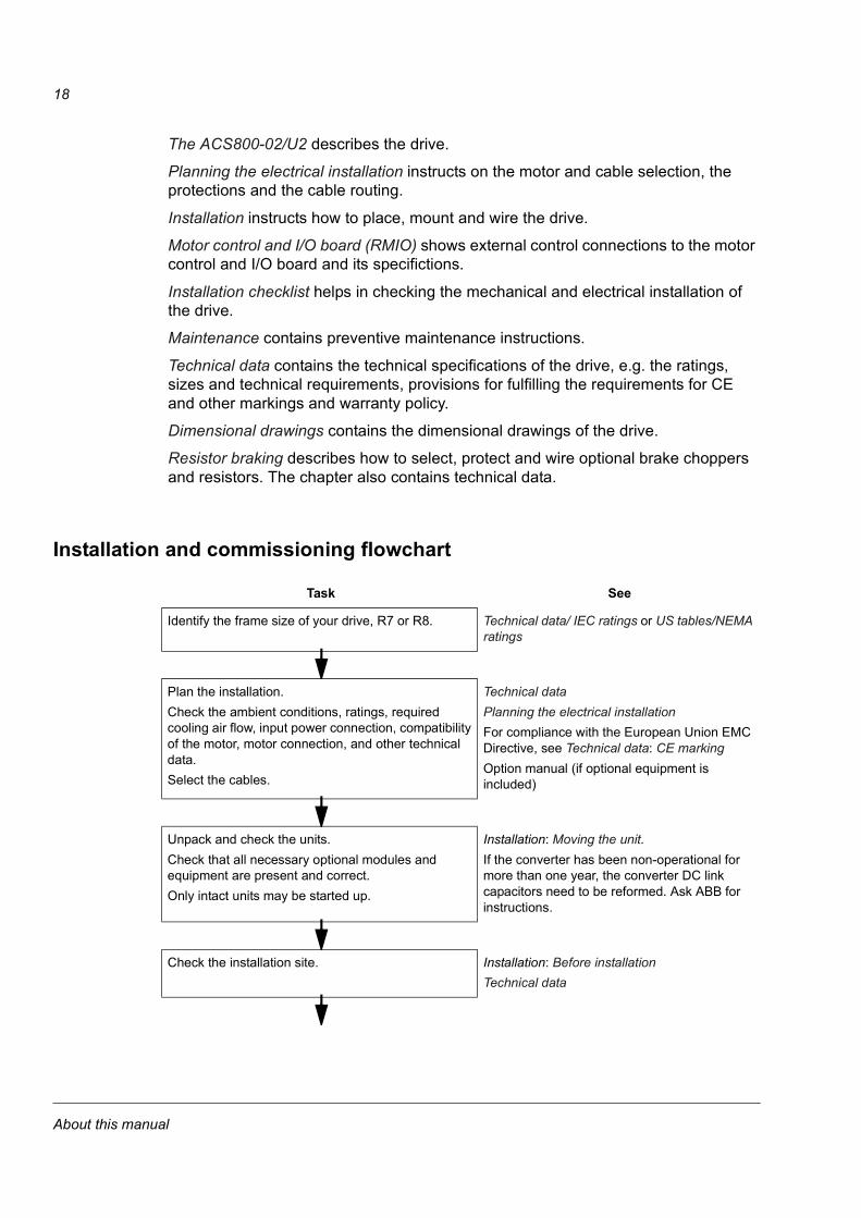
Installation and commissioning flowchart
Task See
Identify the frame size of your drive, R7 or R8. Technical data/ IEC ratings or US tables/NEMA ratings
Plan the installation.Check the ambient conditions, ratings, required cooling air flow, input power connection, compatibility of the motor, motor connection, and other technical data.Select the cables.
Technical dataPlanning the electrical installationFor compliance with the European Union EMC Directive, see Technical data: CE markingOption manual (if optional equipment is included)
Unpack and check the units. Check that all necessary optional modules and equipment are present and correct.Only intact units may be started up.
Installation: Moving the unit.If the converter has been non-operational for more than one year, the converter DC link capacitors need to be reformed. Ask ABB for instructions.
Check the installation site. Installation: Before installationTechnical data
About this manual

19
InquiriesAddress any inquiries about the product to the local ABB representative, quoting the type code and the serial number of the unit. If the local ABB representative cannot be contacted, address inquiries to the manufacturing facility (addresses and phone numbers are on the back cover of this manual).
Check the insulation of the motor and the motor cable.
Installation: Checking the insulation of the assembly
If the drive is about to be connected to an IT (ungrounded) system, check that the drive is not equipped with EMC filter +E202.
The ACS800-02/U2: Type code. For instructions on how to disconnect the EMC filtering, contact ABB.
Route the cables. Planning the electrical installation: Routing the cablesFor compliance with the European Union EMC Directive, see Technical data: CE marking
Install the drive. Connect the power cables. Connect the control and the auxiliary control cables.
Installation, Resistor braking (optional)
Check the installation. Installation checklist
Commission the drive. Appropriate firmware manual
Commission the optional brake chopper (if present). Resistor braking
Task See
About this manual

20
About this manual

21
The ACS800-02/U2
What this chapter containsThis chapter describes the construction and operating principle of the drive in short.
The ACS800-02/U2The ACS800-02 is a free-standing drive for controlling AC motors. In the basic unit, the cabling direction is from below. When an optional enclosure extension is connected next to the basic unit, the cables can also be led from above. The ACS800-U2 is a US version of the drive.
Front covers
Lead-through plate
ACS800-02Enclosure extension
Pedestal inside the unit
Alternative slot for the control panel
Control panel CDP312R
ACS800-U2
The ACS800-02/U2

22
Enclosure extensionThe extension can be used for accommodating customer equipment; it is also automatically added whenever required by factory-installed options such as
• switch fuse (always included with the enclosure extension)
• line contactor with Category 0 emergency stop devices (start/stop and emergency stop switches included)
• thermistor relay(s)
• Pt100 relays
• top cable entry/exit
• additional I/O terminal block.
Type codeThe type code contains information on the specifications and configuration of the drive. The first digits from left express the basic configuration (e.g. ACS800-02-0170-5). The optional selections are given thereafter, separated by + signs (e.g. +E202). The main selections are described below. Not all selections are available for all types. For more information, refer to ACS800 Ordering Information (EN code: 64556568, available on request).
Type code selections for the ACS800-02Selection AlternativesProduct series ACS800 product seriesType 02 free standing. When no options are selected: 6-pulse diode input bridge, IP 21,
Control Panel CDP312R, no EMC filter, Standard Application Program, no enclosure extension, cabling from below, boards without coating, one set of manuals.
Size Refer to Technical data: IEC ratingsVoltage range (nominal rating in bold)
2 208/220/230/240 VAC3 380/400/415 VAC5 380/400/415/440/460/480/500 VAC
+ optionsConstruction C111 enclosure extension (bottom entry/exit, switch fuse with gG fuses)
C127 US enclosure extension (US door interlock disconnect switch fuse, US gland/conduit plate, all components UL/cUL approved)
Resistor braking D150 brake chopperFilter E202 EMC/RFI filter for first environment TN (grounded) system, restricted (the A limits)
E210 EMC/RFI filter for second environment TN/IT (grounded/ungrounded) systemE208 common mode filterE209 light common mode filter
Line options (+C111 or +C127 required)
F250 line contactor Q951 emergency stop of category 0 F260 ultrarapid line fuses (aR)
Cabinet options (+C111 +C127 required)
G304 115 VAC auxiliary voltage transformer
Cabling H351 top entry (+C111+H353 required) H353 top exit (+C111+H351 required)H358 US/UK gland/conduit plate
The ACS800-02/U2

23
Control panel 0J400 no control panel, LEDs on the panel mounting platform includedI/O L504 additional terminal block X2 (+C111 required)
L505 thermistor relay (1 or 2 pcs, +C111 required)L506 Pt100 relay (3 pcs, +C111 required)L... Refer to ACS800 Ordering Information (EN code: 64556568).
Fieldbus K... Refer to ACS800 Ordering Information (EN code: 64556568).Application program N...Language of manual R...Specialities P901 coated boards
P904 extended warranty
Type code selections for the ACS800-U2Selection AlternativesProduct series ACS800 product seriesType U2 free standing (USA). When no options are selected: 6-pulse diode bridge, UL type 1,
Control Panel CDP312R, no EMC filter, US version of the Standard Application Program (three-wire start/stop as default setting), US enclosure extension (top entry, top exit), US gland/conduit plate, common mode filter in frame size R8, boards without coating, one set of manuals.
Size Refer to Technical data: NEMA ratings.Voltage range (nominal rating in bold)
2 208/220/230/240 VAC5 380/400/415/440/460/480 VAC
+ optionsConstruction 0C111 no enclosure extension, bottom entry/exit of cablesResistor braking D150 brake chopperFilter E202 EMC/RFI filter for first environment TN (grounded) system, restricted (the A limits)
E210 EMC/RFI filter for second environment TN/IT (grounded/ungrounded) systemE208 common mode filter for frame size R7E209 light common mode filter for frame size R7
Line options (enclosure extension required)
F250 line contactor Q951 emergency stop of category 0
Cabinet options (enclosure extension required)
G320 230 VAC auxiliary voltage transformer
Cabling H350 bottom entry (+H352 required) H352 bottom exit ( +H350 required)H357 European lead-through plate
Control panel 0J400 no control panel, LEDs on the panel mounting platform includedI/O L504 additional terminal block X2 (+C111 required)
L505 thermistor relay (1 or 2 pcs, +C111 required)L506 Pt100 relay (3 pcs, +C111 required)L... Refer to ACS800 Ordering Information (EN code: 64556568).
Fieldbus K... Refer to ACS800 Ordering Information (EN code: 64556568).Application program N...Language of manual R...
Type code selections for the ACS800-02Selection Alternatives
The ACS800-02/U2

24
Main circuit and control
DiagramThis diagram shows the control interfaces and the main circuit of the drive.
Specialities P901 coated boardsP904 extended warranty
Type code selections for the ACS800-U2Selection Alternatives
~= ~
=
Motor control and I/O board (RMIO)
External control via analogue/digital inputs and outputs
Input power Output power
Optional module 1: RMBA, RAIO, RDIO, RDNA, RLON, RIBA, RPBA, RCAN, RCNA, RMBP, RETA or RTAC
Optional module 2: RTAC, RAIO or RDIO
Optional module 3: RDCO-01, RDCO-02 or RDCO-03
R- UDC+ UDC-R+
Brake chopper in frame sizes R2 and R3 (optional in other frame sizes)
The ACS800-02/U2

25
OperationThis table describes the operation of the main circuit in short.
Printed circuit boardsThe drive contains the following printed circuit boards as standard:
• main circuit board (AINT)
• motor control and I/O board (RMIO-02) with a fibre optic link to the AINT board
• input bridge control board (AINP)
• input bridge protection board (AIBP) which includes varistors, snubbers for the thyristors
• power supply board (APOW)
• gate driver control board (AGDR)
• diagnostics and panel interface board (ADPI)
• EMC filter boards (NRFC) with option +E202
• brake chopper control board (ABRC) with option +D150
Motor controlThe motor control is based on the Direct Torque Control (DTC) method. Two phase currents and DC link voltage are measured and used for the control. The third phase current is measured for earth fault protection.
Component Description
six-pulse rectifier converts the three-phase AC voltage to DC voltage
capacitor bank energy storage which stabilizes the intermediate circuit DC voltage
six-pulse IGBT inverter converts the DC voltage to AC voltage and vice versa. The motor operation is controlled by switching the IGBTs.
The ACS800-02/U2

26
The ACS800-02/U2

27
Planning the electrical installation
What this chapter containsThis chapter contains the instructions that you must follow when selecting the motor, the cables, the protections, the cable routing and the way of operation for the drive system. Always follow local regulations.
Note: If the recommendations given by ABB are not followed, the drive may experience problems that the warranty does not cover.
To which products this chapter appliesThis chapter applies to the ACS800-01/U1, the ACS800-02/U2, the ACS800-04/U4 and ACS800-07/U7 types up to -0610-x.
Checking the compatibility of the motorSee Technical data for the drive ratings and the motor connection data.
WARNING! Operation is not allowed if the motor nominal voltage is less than 1/2 of the drive nominal input voltage. The allowed range of the motor nominal current is 1/6 ... 2 · I2hd of the drive in DTC control and 0 ... 2 · I2hd in scalar control. The control mode is selected by a drive parameter.
Protecting the motor winding and bearingsThe output of the drive comprises – regardless of output frequency – pulses of approximately 1.35 times the mains network voltage with a very short rise time. This is the case with all drives employing modern IGBT inverter technology.
The voltage of the pulses can be almost double at the motor terminals, depending on the motor cable properties. This in turn can cause additional stress on the motor insulation.
Modern variable speed drives with their fast rising voltage pulses and high switching frequencies can cause current pulses through the motor bearings which can gradually erode the bearing races.
The stress on motor insulation can be avoided by using optional ABB du/dt filters. du/dt filters also reduce bearing currents.
Planning the electrical installation

28
To avoid damage to motor bearings, insulated N-end (non-driven end) bearings and output filters from ABB must be used according to the following table. In addition, the cables must be selected and installed according to the instructions given in this manual. Three types of filters are used individually or in combinations:
• optional du/dt filter (protects motor insulation system and reduces bearing currents).
• common mode filter (mainly reduces bearing currents)
• light common mode filter (mainly reduces bearing currents).
The common mode filter is composed of toroidal cores installed inside the drive at the factory.
Requirements tableThe following table shows how to select the motor insulation system and when optional ABB du/dt filter, insulated N-end (non-driven end) motor bearings and ABB common mode filters are required. The motor manufacturer should be consulted regarding the construction of the motor insulation and additional requirements for explosion-safe (EX) motors. Failure of the motor to fulfil the following requirements or improper installation may shorten motor life or damage the motor bearings.
Man
ufac
ture
r
Motor type Nominal mains voltage (AC line
voltage)
Requirement forMotor insulation
system ABB du/dt filter, insulated N-end bearing and ABB common mode
filterPN < 100 kW
andframe size < IEC 315
100 kW < PN < 350 kW or
frame size > IEC 315
PN > 350 kWor
frame size > IEC 400
PN < 134 HPand frame size <
NEMA 500
134 HP < PN < 469 HPor frame size >
NEMA 500
PN > 469 HP
ABB
Random-wound M2_ and M3_
UN < 500 V Standard - + N + N + CMF
500 V < UN < 600 V Standard + du/dt + du/dt + N + du/dt + N + LCMF
or
Reinforced - + N + N + CMF
600 V < UN < 690 V Reinforced + du/dt + du/dt + N + du/dt + N + LCMF
Form-wound HXR and AM_
380 V < UN < 690 V Standard n.a. + N + CMF + N + CMF
Old* form-wound HX_ and modular
380 V < UN < 690 V Check with the motor manufacturer.
+ du/dt with voltages over 500 V + N + CMF
Random-wound HXR and AM_
380 V < UN < 690 V Check with the motor manufacturer.
+ du/dt with voltages over 500 V + N + CMF
Planning the electrical installation

29
* manufactured before 1992
Note 1: The abbreviations used in the table are defined below.
NON-ABB
Random-wound and form-wound
UN < 420 V Standard: ÛLL = 1300 V
- + N or CMF + N + CMF
420 V < UN < 500 V Standard: ÛLL = 1300 V
+ du/dt + du/dt + N + du/dt + N + CMF
or
+ du/dt + CMF
or
Reinforced: ÛLL = 1600 V, 0.2 microsecond rise time
- + N or CMF + N + CMF
500 V < UN < 600 V Reinforced: ÛLL = 1600 V
+ du/dt + du/dt + N + du/dt + N + LCMF
or
+ du/dt + CMF
or
Reinforced: ÛLL = 1800 V
- + N or CMF + N + CMF
600 V < UN < 690 V Reinforced: ÛLL = 1800 V
+ du/dt + du/dt + N + du/dt + N + LCMF
Form-wound 600 V < UN < 690 V Reinforced: ÛLL = 2000 V, 0.3 microsecond rise time
n.a. N + CMF N + CMF
Abbreviation DefinitionUN nominal voltage of the supply network
ÛLL peak line-to-line voltage at motor terminals which the motor insulation must withstand
PN motor nominal power
du/dt du/dt filter at the output of the drive
CMF common mode filter +E208 (3 toroidal cores)
LCMF light common mode filter +E209 (1 toroidal core)
N N-end bearing: insulated motor non-driven end bearing
n.a. Motors of this power range are not available as standard units. Consult the motor manufacturer.
Man
ufac
ture
r
Motor type Nominal mains voltage (AC line
voltage)
Requirement forMotor insulation
system ABB du/dt filter, insulated N-end bearing and ABB common mode
filterPN < 100 kW
andframe size < IEC 315
100 kW < PN < 350 kW or
frame size > IEC 315
PN > 350 kWor
frame size > IEC 400
PN < 134 HPand frame size <
NEMA 500
134 HP < PN < 469 HPor frame size >
NEMA 500
PN > 469 HP
Planning the electrical installation

30
Note 2: Explosion-safe (EX) motorsThe motor manufacturer should be consulted regarding the construction of the motor insulation and additional requirements for explosion-safe (EX) motors. Note 3: High-output motors and IP 23 motorsFor motors with higher rated output than what is stated for the particular frame size in EN 50347 (2001) and for IP 23 motors, the requirements of range “100 kW < PN < 350 kW” apply to motors with 40 kW < PN < 100 kW. The requirements of range “PN > 350 kW” apply to motors with PN within the range of “100 kW < PN < 350 kW”.Note 4: HXR and AMA motors All AMA machines (manufactured in Helsinki) to be supplied by a drive have form-wound windings. All HXR machines manufactured in Helsinki since 1997 have form-wound windings.Note 5: ABB motors of types other than M2_, M3_, HX_ and AM_ Select according to non-ABB motors.Note 6: Resistor braking of the drive When the drive is in braking mode for a large part of its operation time, the intermediate circuit DC voltage of the drive increases, the effect being similar to increasing the supply voltage by up to 20 percent. The voltage increase should be taken into consideration when determining the motor insulation requirement. Example: Motor insulation requirement for a 400 V application must be selected as if the drive were supplied with 480 V.
Permanent magnet synchronous motorOnly one permanent magnet motor can be connected to the inverter output.
Install a safety switch between a permanent magnet synchronous motor and the motor cable. The switch is needed to isolate the motor during any maintenance work in the drive.
Supply connection
Disconnecting device (means)ACS800-01, ACS800-U1, ACS800-02 and ACS800-U2 without the enclosure extension, ACS800-04, ACS800-U4
Install a hand-operated input disconnecting device (means) between the AC power source and the drive. The disconnecting device must be of a type that can be locked to the open position for installation and maintenance work.
ACS800-U2 with the enclosure extension, ACS800-07 and ACS800-U7
These units are equipped with a hand-operated input disconnecting device (means) which isolates the drive and the motor from the AC power as standard. The disconnecting device does not, however, isolate the input busbars from the AC power. Therefore during installation and maintenance work on the drive, the input cables and busbars must be isolated from the input power with a disconnector at the distribution board or at the supplying transformer.
Planning the electrical installation

31
EU
To meet the European Union Directives, according to standard EN 60204-1, Safety of Machinery, the disconnecting device must be one of the following types:
• a switch-disconnector of utilization category AC-23B (EN 60947-3)
• a disconnector that has an auxiliary contact that in all cases causes switching devices to break the load circuit before the opening of the main contacts of the disconnector (EN 60947-3)
• a circuit breaker suitable for isolation in accordance with EN 60947-2.
US
The disconnecting means must conform to the applicable safety regulations.
FusesSee section Thermal overload and short-circuit protection.
Thermal overload and short-circuit protectionThe drive protects itself and the input and motor cables against thermal overload when the cables are dimensioned according to the nominal current of the drive. No additional thermal protection devices are needed.
WARNING! If the drive is connected to multiple motors, a separate thermal overload switch or a circuit breaker must be used for protecting each cable and motor. These devices may require a separate fuse to cut off the short-circuit current.
The drive protects the motor cable and the motor in a short-circuit situation when the motor cable is dimensioned according to the nominal current of the drive.
Mains cable (AC line cable) short-circuit protectionAlways protect the input cable with fuses. Size the fuses according to local safety regulations, appropriate input voltage and the rated current of the drive (see Technical Data).
ACS800-01/U1, ACS800-02/U2 without enclosure extension and ACS800-04/U4
When placed at the distribution board, standard gG (US: CC or T for the ACS800-U1; T or L for the ACS800-U2 and the ACS800-U4) fuses will protect the input cable in short-circuit situations, restrict drive damage and prevent damage to adjoining equipment in case of a short-circuit inside the drive.
Planning the electrical installation

32
Drive AC fuses (ACS800-07/U7 and ACS800-02/U2 with enclosure extension)ACS800-07/U7 units and ACS800-02/U2 units with enclosure extension are equipped with standard gG (US: T/L) or optional aR fuses listed in Technical Data. The fuses restrict drive damage and prevent damage to adjoining equipment in case of a short-circuit inside the drive.
Operating time of the fusesCheck that the operating time of the fuse is below 0.5 seconds. The operating time depends on the fuse type (gG or aR), supply network impedance and the cross-sectional area, material and length of the supply cable. In case the 0.5 seconds operating time is exceeded with gG (US: CC/T/L) fuses, ultrarapid (aR) fuses will in most cases reduce the operating time to an acceptable level. The US fuses must be of the “non-time delay” type.
For fuse ratings, see Technical Data.
WARNING! Circuit breakers are not capable of providing sufficient protection because they are inherently slower than fuses. Always use fuses with circuit breakers.
Ground fault protectionThe drive is equipped with an internal ground fault protective function to protect the unit against ground faults in the motor and the motor cable. This is not a personal safety or a fire protection feature. The ground fault protective function can be disabled with a parameter, refer to the appropriate ACS800 Firmware Manual.
The EMC filter of the drive includes capacitors connected between the main circuit and the frame. These capacitors and long motor cables increase the ground leakage current and may cause fault current circuit breakers to function.
Emergency stop devicesFor safety reasons, install the emergency stop devices at each operator control station and at other operating stations where emergency stop may be needed.
Note: Pressing the stop key ( ) on the control panel of the drive does not generate an emergency stop of the motor or separate the drive from dangerous potential.
ACS800-02/U2 with enclosure extension and ACS800-07/U7An emergency stop function is optionally available for stopping and switching off the whole drive. Two stop categories according to IEC/EN 60204-1 (1997) are available: immediate removal of power (Category 0 for ACS800-02/U2 and ACS800-07/U7) and controlled emergency stop (Category 1 for ACS800-07/U7).
Planning the electrical installation

33
Restarting after an emergency stop
After an emergency stop, the emergency stop button must be released and the drive started by turning the operating switch of the drive from position “ON” to “START”.
Prevention of Unexpected Start (ACS800-07/U7 only)The drive can be equipped with an optional Prevention of Unexpected Start function according to standards IEC/EN 60204-1: 1997; ISO/DIS 14118: 2000 and EN 1037: 1996.
The Prevention of Unexpected Start function disables the control voltage of the power semiconductors, thus preventing the inverter from generating the AC voltage required to rotate the motor. By using this function, short-time operations (like cleaning) and/or maintenance work on non-electrical parts of the machinery can be performed without switching off the AC power supply to the drive.
The operator activates the Prevention of Unexpected Start function by opening a switch on a control desk. An indicating lamp on the control desk will light, signalling that the prevention is active. The switch can be locked out.
The user must install on a control desk near the machinery:
• switching/disconnecting device for the circuitry. “Means shall be provided to prevent inadvertent, and/or mistaken closure of the disconnecting device.” EN 60204-1: 1997.
• indicating lamp; on = starting the drive is prevented, off = drive is operative.
For connections to the drive, see the circuit diagram delivered with the drive.
WARNING! The Prevention of Unexpected Start function does not disconnect the voltage of the main and auxiliary circuits from the drive. Therefore maintenance work on electrical parts of the drive or the motor can only be carried out after isolating the drive system from the main supply.
Note: When a running drive is stopped by using the Prevention of Unexpected Start function, the drive will stop by coasting. If this is not acceptable (e.g. causes danger), the drive and machinery must be stopped using the appropriate stopping mode before using this function.
Planning the electrical installation

34
Selecting the power cables
General rulesDimension the mains (input power) and motor cables according to local regulations:
• The cable must be able to carry the drive load current. See chapter Technical data for the rated currents.
• The cable must be rated for at least 70 °C maximum permissible temperature of conductor in continuous use. For US, see Additional US requirements.
• The inductance and impedance of the PE conductor/cable (grounding wire) must be rated according to permissible touch voltage appearing under fault conditions (so that the fault point voltage will not rise excessively when an ground fault occurs).
• 600 VAC cable is accepted for up to 500 VAC. For 690 VAC rated equipment, the rated voltage between the conductors of the cable should be minimum 1 kV.
For drive frame size R5 and larger, or motors larger than 30 kW (40 HP), symmetrical shielded motor cable must be used (figure below). A four-conductor system can be used up to frame size R4 with up to 30 kW (40 HP) motors, but shielded symmetrical motor cable is recommended.
A four-conductor system is allowed for input cabling, but shielded symmetrical cable is recommended. To operate as a protective conductor, the shield conductivity must be as follows when the protective conductor is made of the same metal as the phase conductors:
Compared to a four-conductor system, the use of symmetrical shielded cable reduces electromagnetic emission of the whole drive system as well as motor bearing currents and wear.
The motor cable and its PE pigtail (twisted shield) should be kept as short as possible in order to reduce electromagnetic emission.
Cross-sectional area of the phase conductors
S (mm2)
Minimum cross-sectional area of the corresponding protective conductor
Sp (mm2) S < 16 S
16 < S < 36 1635 < S S/2
Planning the electrical installation

35
Alternative power cable typesPower cable types that can be used with the drive are represented below.
Motor cable shieldTo effectively suppress radiated and conducted radio-frequency emissions, the shield conductivity must be at least 1/10 of the phase conductor conductivity. The requirements are easily met with a copper or aluminium shield. The minimum requirement of the motor cable shield of the drive is shown below. It consists of a concentric layer of copper wires with an open helix of copper tape. The better and tighter the shield, the lower the emission level and the bearing currents.
Symmetrical shielded cable: three phase conductors and a concentric or otherwise symmetrically constructed PE conductor, and a shield
Recommended
PE conductor and shield
Shield Shield
A separate PE conductor is required if the conductivity of the cable shield is < 50 % of the conductivity of the phase conductor.
A four-conductor system: three phase conductors and a protective conductor.
Shield
PE
PE
PE
Not allowed for motor cables with phase conductor cross section larger than 10 mm2 [motors > 30 kW (40 HP)].
Not allowed for motor cables
Insulation jacket Copper wire screen Helix of copper tape
Cable core
Inner insulation
Planning the electrical installation

36
Additional US requirementsType MC continuous corrugated aluminum armor cable with symmetrical grounds or shielded power cable must be used for the motor cables if metallic conduit is not used. For the North American market, 600 VAC cable is accepted for up to 500 VAC. 1000 VAC cable is required above 500 VAC (below 600 VAC). For drives rated over 100 amperes, the power cables must be rated for 75 °C (167 °F).
Conduit
Where conduits must be coupled together, bridge the joint with a ground conductor bonded to the conduit on each side of the joint. Bond the conduits also to the drive enclosure. Use separate conduits for input power, motor, brake resistors, and control wiring. Do not run motor wiring from more than one drive in the same conduit.
Armored cable / shielded power cable
The motor cables can be run in the same cable tray as other 460 V or 600 V power wiring. Control and signal cables must not be run in the same tray as power cables. Six conductor (3 phases and 3 ground) type MC continuous corrugated aluminum armor cable with symmetrical grounds is available from the following suppliers (trade names in parentheses):
• Anixter Wire & Cable (Philsheath)
• BICC General Corp (Philsheath)
• Rockbestos Co. (Gardex)
• Oaknite (CLX).
Shielded power cables are available from Belden, LAPPKABEL (ÖLFLEX) and Pirelli.
Power factor compensation capacitorsDo not connect power factor compensation capacitors or surge absorbers to the motor cables (between the drive and the motor). They are not designed to be used with drives, and will degrade motor control accuracy. They can cause permanent damage to the drive or themselves due to the rapid changes in the drive output voltage.
If there are power factor compensation capacitors in parallel with the three phase input of the drive, ensure that the capacitors and the drive are not charged simultaneously to avoid voltage surges which might damage the unit.
Planning the electrical installation
37
Equipment connected to the motor cable
Installation of safety switches, contactors, connection boxes, etc.To minimize the emission level when safety switches, contactors, connection boxes or similar equipment are installed in the motor cable (i.e. between the drive and the motor):
• EU: Install the equipment in a metal enclosure with 360 degrees grounding for the shields of both the incoming and outgoing cable, or connect the shields of the cables otherwise together.
• US: Install the equipment in a metal enclosure in a way that the conduit or motor cable shielding runs consistently without breaks from the drive to the motor.
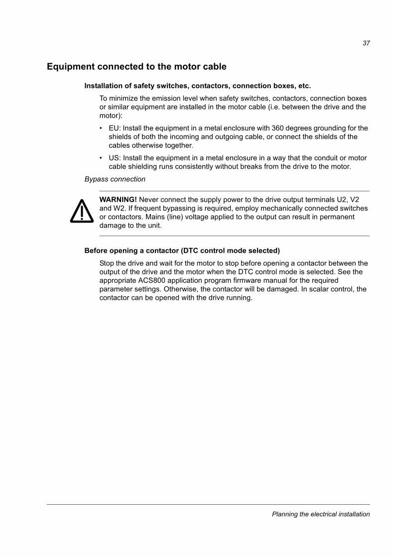
Bypass connection
WARNING! Never connect the supply power to the drive output terminals U2, V2 and W2. If frequent bypassing is required, employ mechanically connected switches or contactors. Mains (line) voltage applied to the output can result in permanent damage to the unit.
Before opening a contactor (DTC control mode selected)Stop the drive and wait for the motor to stop before opening a contactor between the output of the drive and the motor when the DTC control mode is selected. See the appropriate ACS800 application program firmware manual for the required parameter settings. Otherwise, the contactor will be damaged. In scalar control, the contactor can be opened with the drive running.
Planning the electrical installation

38
Protecting the relay output contacts and attenuating disturbances in case of inductive loads
Inductive loads (relays, contactors, motors) cause voltage transients when switched off.
The relay contacts on the RMIO board are protected with varistors (250 V) against overvoltage peaks. In spite of this, it is highly recommended to equip inductive loads with noise attenuating circuits [varistors, RC filters (AC) or diodes (DC)] in order to minimize the EMC emission at switch-off. If not suppressed, the disturbances may connect capacitively or inductively to other conductors in the control cable and form a risk of malfunction in other parts of the system.
Install the protective component as close to the inductive load as possible. Do not install protective components at the RMIO board terminal block.
24 VDC
230 VAC
X25
1 RO12 RO13 RO1
X26
1 RO22 RO23 RO2
X27
1 RO32 RO33 RO3
Relay outputsRMIO
230 VAC
Diode
Varistor
RC filter
Planning the electrical installation

39
Selecting the control cablesAll control cables must be shielded.
Use a double-shielded twisted pair cable (Figure a, e.g. JAMAK by NK Cables, Finland) for analogue signals. This type of cable is recommended for the pulse encoder signals also. Employ one individually shielded pair for each signal. Do not use common return for different analogue signals.
A double-shielded cable is the best alternative for low-voltage digital signals but single-shielded twisted multipair cable (Figure b) is also usable.
Run analogue and digital signals in separate, shielded cables.
Relay-controlled signals, providing their voltage does not exceed 48 V, can be run in the same cables as digital input signals. It is recommended that the relay-controlled signals be run as twisted pairs.
Never mix 24 VDC and 115 / 230 VAC signals in the same cable.
Relay cableThe cable type with braided metallic screen (e.g. ÖLFLEX by LAPPKABEL, Germany) has been tested and approved by ABB.
Control panel cableIn remote use, the cable connecting the control panel to the drive must not exceed 3 metres (10 ft). The cable type tested and approved by ABB is used in control panel option kits.
aA double shielded twisted pair cable
bA single shielded twisted multipair cable
Planning the electrical installation

40
Connection of a motor temperature sensor to the drive I/O
WARNING! IEC 60664 requires double or reinforced insulation between live parts and the surface of accessible parts of electrical equipment which are either non-conductive or conductive but not connected to the protective earth.
To fulfil this requirement, the connection of a thermistor (and other similar components) to the digital inputs of the drive can be implemented in three alternate ways:
1. There is double or reinforced insulation between the thermistor and live parts of the motor.
2. Circuits connected to all digital and analogue inputs of the drive are protected against contact and insulated with basic insulation (the same voltage level as the drive main circuit) from other low voltage circuits.
3. An external thermistor relay is used. The insulation of the relay must be rated for the same voltage level as the main circuit of the drive. For connection, see ACS800 Firmware Manual.
Routing the cablesRoute the motor cable away from other cable routes. Motor cables of several drives can be run in parallel installed next to each other. It is recommended that the motor cable, input power cable and control cables be installed on separate trays. Avoid long parallel runs of motor cables with other cables in order to decrease electromagnetic interference caused by the rapid changes in the drive output voltage.
Where control cables must cross power cables make sure they are arranged at an angle as near to 90 degrees as possible. Do not run extra cables through the drive.
The cable trays must have good electrical bonding to each other and to the grounding electrodes. Aluminium tray systems can be used to improve local equalizing of potential.
Planning the electrical installation

41
A diagram of the cable routing is below.
Control cable ducts
90 ° min 500 mm (20 in.)
Motor cable Input power cable
Control cables
min 200 mm (8 in.)
min 300 mm (12 in.)
Motor cable
Power cable
Drive
230 V24 V24 V 230 V
Lead 24 V and 230 V control cables in separate ducts inside the cabinet.
Not allowed unless the 24 V cable is insulated for 230 V or insulated with an insulation sleeving for 230 V.
Planning the electrical installation

42
Planning the electrical installation

43
Installation
What this chapter containsThis chapter describes the mechanical and electrical installation procedure of the drive.
WARNING! Only qualified electricians are allowed to carry out the work described in this chapter. Follow the Safety instructions on the first pages of this manual. Ignoring the safety instructions can cause injury or death.
Moving the unitMove the transport package by pallet truck to the installation site. Unpack the package as shown below.
Lifting when the enclosure extension is included
Installation

44
WARNING! The drive is heavy [frame size R7: 100 kg (220 lb), frame size R8: 230 kg (507 lb)]. Lift the drive by the upper part only using the lifting lugs attached to the top of the unit. The lower part will be deformed from lifting. Do not remove the pedestal before lifting.
Do not tilt the drive. The centre of gravity of the unit is high. The unit will overturn from a tilt of about 6 degrees.
Do not wheel the drive except for installation (the front direction is preferable because the front wheels are steadier). The drive frame may be deformed from wheeling when the pedestal is removed. If the drive is moved over long distances, place it on its back on a pallet and move it by fork-lift.
Do not lift by the lower part of the frame.
Max
30°
FrontBack
Do not tilt! Do not wheel over long distances.
Frame size R8:The support legs must be locked to open position during the installation and always when wheeling the unit.
Installation

45
Before installation
Delivery checkThe drive is delivered in a box that also contains:
• hardware manual
• appropriate firmware manuals and guides
• optional module manuals
• delivery documents.
Check that there are no signs of damage. Before attempting installation and operation, check the information on the type designation label of the drive to verify that the unit is of the correct type. The label includes an IEC and NEMA rating, UL, C-UL, CSA and CE markings, a type code and a serial number, which allow individual recognition of each unit. The first digit of the serial number refers to the manufacturing plant. The next four digits refer to the unit’s manufacturing year and week respectively. The remaining digits complete the serial number so that there are no two units with the same serial number.
The type designation label is located under the front visor and the serial number label inside the unit. Example labels are shown below.
Type designation label
Serial number label
Installation

46
Requirements for the installation siteThe drive must be installed in an upright position on floor (or wall). Check the installation site according to the requirements below. Refer to Dimensional drawings for frame details. See Technical data for the allowed operation conditions of the drive.
Wall
The wall/material near the unit must be of non-flammable material. Check that there is nothing on the wall to inhibit the installation.
If a unit is mounted on the wall, the wall must be as close to vertical as possible, and strong enough to carry the weight of the unit. The drive must not be installed without the pedestal and a support shelf on wall, refer to ACS800-02/U2 Application Note on Wall Mounting [68250013 (English)].
Floor
The floor/material below the installation should be non-flammable. The floor must be horizontal.
Free space around the unit
See section Installation procedure: Choose the mounting orientation (a, b, c or d).
Cooling air flowProvide the drive with the amount of fresh cooling air given in Technical data / IEC ratings or US tables.
The cooling air will enter the unit from the front air grating and flow upwards inside the unit. Recirculating cooling air into the unit is not allowed.
Installation

47
IT (ungrounded) systems A drive equipped with no EMC filter or with EMC filter +E210 is suitable for IT (ungrounded systems). If the drive is equipped with EMC filter +E202, disconnect the filter before connecting the drive to an ungrounded system. For detailed instructions on how to do this, please contact your local ABB representative.
WARNING! If a drive with EMC filter +E202 is installed on an IT system [an ungrounded power system or a high resistance-grounded (over 30 ohms) power system], the system will be connected to earth potential through the EMC filter capacitors of the drive. This may cause danger or damage the unit.
Required tools• set of screw drivers
• torque wrench with 500 mm (20 in.) or 2 x 250 mm (2 x 10 in.) extension bar
• 19 mm (3/4 in.) socketfor frame size R7: 13 mm (1/2 in.) magnetic end socket for frame size R8: 17 mm (11/16 in.) magnetic end socket.
Checking the insulation of the assemblyEvery drive has been tested for insulation between the main circuit and the chassis (2500 V rms 50 Hz for 1 second) at the factory. Therefore, do not make any voltage tolerance or insulation resistance tests (e.g. hi-pot or megger) on any part of the drive. Check the insulation of the assembly as follows.
WARNING! Check the insulation before connecting the drive to the mains. Make sure that the drive is disconnected from the mains (input power).
1. Check that the motor cable is disconnected from the drive output terminals U2, V2 and W2.
2. Measure the insulation resistances of the motor cable and the motor between each phase and the Protective Earth by using a measuring voltage of 1 kV DC. The insulation resistance must be higher than 1 Mohm.
PE
ohmM
Installation
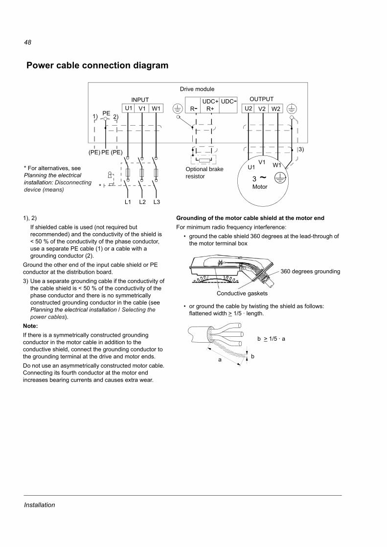
48
Power cable connection diagram
INPUT OUTPUT
U1V1 W1
3 ~Motor
U1 V1 W11)
U2 V2 W2UDC+
R+UDC-
R-
L1 L2 L3
(PE) (PE)PE
2)
3)
Drive module
PE
* For alternatives, see Planning the electrical installation: Disconnecting device (means)
Optional brake resistor
*
Grounding of the motor cable shield at the motor endFor minimum radio frequency interference:
• ground the cable shield 360 degrees at the lead-through of the motor terminal box
• or ground the cable by twisting the shield as follows: flattened width > 1/5 · length.
360 degrees grounding
Conductive gaskets
a b
b > 1/5 · a
1), 2)If shielded cable is used (not required but recommended) and the conductivity of the shield is < 50 % of the conductivity of the phase conductor, use a separate PE cable (1) or a cable with a grounding conductor (2).
Ground the other end of the input cable shield or PE conductor at the distribution board.3) Use a separate grounding cable if the conductivity of
the cable shield is < 50 % of the conductivity of the phase conductor and there is no symmetrically constructed grounding conductor in the cable (see Planning the electrical installation / Selecting the power cables).
Note: If there is a symmetrically constructed grounding conductor in the motor cable in addition to the conductive shield, connect the grounding conductor to the grounding terminal at the drive and motor ends. Do not use an asymmetrically constructed motor cable. Connecting its fourth conductor at the motor end increases bearing currents and causes extra wear.
Installation

49
Installation procedure
Choose the mounting orientation (a, b, c or d)
* space for the installer not included** space for fan and capacitor replacement not included
Mounting orientations a and b
Frame size
Mounting orientation
Required free space around the unit for mounting, maintenance, service and cooling *Front Side Above
mm in. mm in. mm in.R7 a, d 500 20 - - 200 7.9
b - - 500 20 200 7.9c - - 200** 7.9** lifting space lifting space
R8 a, d 600 24 - - 300 12b - - 600 24 300 12c - - 300** 12** lifting space lifting space
Make holes in the wall (recommended): 1. Lift the unit against the wall into the mounting place. 2. Mark the locations for the two fixing points in the wall (not for mounting orientation a if the unit is
subjected to sideways vibration).3. Mark the bottom edges of the unit to the floor.
With enclosure extensionLifted from abovea) b) c)
air inlet surface
d)
wall fixing point (recommended)control panel mounting slot
required free space
Note: The unit can also be installed away from the wall.
Symbols:
Installation

50
Remove the pedestal (frame size R7):1. Remove the lower front covers by undoing the fixing screws.2. Undo the red screws that fix the pedestal to the frame from front.3. Undo the red M8 combi screws (8 pcs or 9 pcs with +D150) that connect the busbars of the pedestal to the upper
frame. Use a torque wrench with an extension bar. 4. Wheel the drive frame out by using the handle.
4
Wheeling the frame out1
2
2
1
33 3
3
ProE: ACS800-02-R7_manual2.drw
2
2
3 3
3 2 pcs
3
Installation
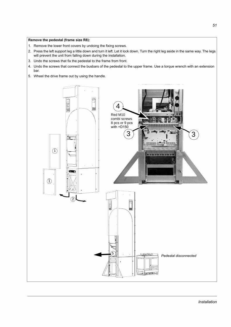
51
Remove the pedestal (frame size R8):1. Remove the lower front covers by undoing the fixing screws.2. Press the left support leg a little down and turn it left. Let it lock down. Turn the right leg aside in the same way. The legs
will prevent the unit from falling down during the installation.3. Undo the screws that fix the pedestal to the frame from front. 4. Undo the screws that connect the busbars of the pedestal to the upper frame. Use a torque wrench with an extension
bar.5. Wheel the drive frame out by using the handle.
1
2
1
3
4
5
Red M10 combi screws8 pcs or 9 pcs
Pedestal disconnected
3with +D150
Installation

52
Fix the lead-through plate to the floor:1. Make a hole in the floor or cable conduit cover below the lead-through plate. See Dimensional
drawings.2. Check that the floor is horizontal with a spirit level.3. Fasten the lead-through plate with screws or bolts.
Note: The screws/bolts will be removed and refastened when the pedestal is fastened through the same holes later on. The lead-through plate can be fastened after leading the cables through it if the cabling procedure is more convenient in that way.
Lead the power (input, motor and optional brake) cables through the lead-through plate:1. Make adequate holes in the grommets to fit them tightly on the cables. 2. Lead the cables through the holes and slide the grommets onto the cables.
These brackets can be removed for the time of the installation
Frame size R7 Frame size R8
W1
W2
Busbars connecting the power cable terminals to the drive module
W1V1
U1R-
PE
W2V2
U2
UDC+UDC-
R+
a floor fixing points
a
a
PE
ProE: 64564439a
a
V1U1
V2
U2
UDC+R+
UDC-
R-
ProE: 64524739
Installation

53
Prepare the power cables: 1. Strip the cables. 2. Twist the shield wires.3. Bend the conductors to the terminals. 4. Cut the conductors to adequate length. Put the pedestal onto the lead-through plate and check the
length of the conductors. Remove the pedestal.5. Crimp or screw cable lugs onto the conductors.
WARNING! The maximum allowed width of the cable lug is 38 mm (1.5 in.). Wider cable lugs may cause a short-circuit.
6. Connect the twisted shields of the cables to the PE terminal.Note: 360 degrees grounding is not needed at the cable entry. The short twisted shield provides, in addition to the protective grounding, also sufficient disturbance suppression.
Frame size R7
Terminal U1, U2 V1, V2 W1, W2 UDC+/R+, R- UDC-A (hole 1) / mm [in.] 159 [6.3] 262 [10.3] 365 [14.4] 58 [2.3] 3 [0.1]A (hole 2) / mm [in.] 115 [4.5] 218 [8.5] 321 [12.6] - -
PE terminal hole 1 2 3 4 5 6B / mm [in.] 43 [1.7] 75 [3.0] 107 [4.2] 139 [5.5] 171 [6.7] 203 [8.0]
64582313
Installation

54
Lead the control cables through the lead-through plate:1. Cut holes in the grommets to fit them tightly onto the control cables. 2. Lead the control cables through the lead-through plate and slide the grommets onto the cables.
Terminal A B A Bhole 1 hole 2 hole 3 hole 1 hole 2 hole 3
mm mm mm mm in. in. in. in.Frame size R8U1 432 387 342 40 17.0 15.2 13.5 1.6V1 148 5.8W1 264 10.4U2 284 239 194 40 11.2 9.4 7.6 1.6V2 148 5.8W2 264 10.4UDC- 136 91 46 40 5.4 3.6 1.8 1.6R- 148 5.8UDC+/R+ 264 10.4
PE terminal hole 1 2 3 4 5 6 7 8 9C / mm [in.] 24 [0.9] 56 [2.2] 88 [3.5] 120 [4.7] 152 [6.0] 184 [7.2] 216 [8.5] 248 [9.8] 280 [11.0]
Frame size R8
64605569
PE
Installation

55
Connect the cable lugs to the pedestal:1. If the lead-through plate is fixed to the floor, undo the fixing screws. 2. Place the pedestal onto the lead-through plate. 3. Fasten the pedestal and the lead-through plate to the floor with the screws through the same holes.4. Connect the cable lugs to the pedestal (U1, V1, W1, U2, V2, W2 and PE; optional brake resistor
cable lugs to UDC+/R+ and R-). 5. Tighten the connections.
WARNING! It is not allowed to connect the cables directly to the drive module terminals. The leadthrough insulation material is not strong enough to carry the mechanical stress exerted by the cables. The cable connections must be performed in the pedestal.
Wheel the drive frame back on the pedestal (See step Remove the pedestal).
4
5
Frame sizes R7 and R8: M12 (1/2 in.) boltTightening torque: 50...75 Nm (37...55 lbf ft)
View of frame size R7
Installation

56
Mounting orientation c (lifting from above)Make the installation otherwise as described in Mounting orientations a and b but leave the pedestal connected to the frame.
• Remove the lead-through plate and the lower front and side plates.
• Lift the drive frame onto the lead-through plate from above.
• Fasten the drive to the floor.
• Connect the cable lugs to the terminals.
• Fasten the lower front and side plates.
• Fasten the drive by top to the wall (recommened).
Note: When mounting the unit on wall, a support shelf is required, see the instructions in ACS800-02/U2 Application Note on Wall Mounting [68250013 (English)].
Fix the pedestal to the drive frame in reverse order to step Remove the pedestal:1. Fix the fastening screws.
WARNING! The fixing is important because the screws are required for the grounding of the drive.
2. Connect the terminals at the top of the pedestal to the terminals at the bottom of the upper part of the drive frame.
WARNING! Be careful not to drop screws inside the pedestal. Loose metal pieces inside the unit may cause damage.
3. Tighten the connections.
Fasten the drive frame to the wall (recommended):Fasten unit with screws or bolts to the holes in the wall.Note: In mounting orientation a, do not fasten the unit to wall if it is subjected to sideways vibration.Connect the control cables as described in section Connecting the control cables.Fasten the covers
2
Terminal connection screwsR7: M8 combi screwsTightening torque: 15...22 Nm (0.59...0.87 lbf ft)R8: M10 combi screwsTightening torque: 30...44 Nm (22...32 lbf ft)1 1
View of frame size R7
Installation

57
Mounting orientation d (optional enclosure extension included)The customer connections of the drive (power cable terminals, I/O terminal blocks, option module slots) are provided in the enclosure extension instead of the actual drive cubicle. The extension cubicle and the drive cubicle are fastened together at the factory with two screws at the top of the cubicles. The drive pedestal is fastened to the base plate of the enclosure extension.
Fastening the unit
See Dimensional drawings for the locations of the fastening points.
Fasten the unit to the floor with four screws using the holes provided in the base plate.
It is recommended to fasten the unit to the rear wall as well. Use the holes at the top of the enclosure extension and at the top of the drive cubicle. The enclosure extension is fastened as follows:
1. Remove the top lead-through plate.
2. Fasten the unit with screws or bolts to the holes in the wall.
3. Fasten the top lead-through plate.
2
2
1
Installation

58
Connecting the Power Cables
Refer to Dimensional drawings for terminal locations and hole sizes. The same screw can be used for connecting two cable lugs (on both sides of the busbar).
Procedure:
• Lead the cables into the cubicle through the cable entries provided. Note: 360 degrees grounding is not needed at the cable entry. The short twisted shield provides, in addition to the protective grounding, also sufficient disturbance suppression.
• Slide the grommets onto the cables.
• Cut the cables to appropriate length.
• Terminate the conductors with cable lugs or connectors.
• Connect the cable shields to the PE busbar.
• Connect the phase conductors of the motor cable to the U2, V2 and W2 terminals.
• Connect the phase conductors of the supply cable to the U1, V1 and W1 terminals.
• Connect the optional brake conductors to the R+ and R- terminals.
Enclosure extension layout
There are two main layouts of the enclosure extension, one for each cabling direction. The pictures below show both the bottom and top entry/exit layouts of the enclosure extension.
Installation

59
Bottom cable entry/exit (R7)
*Add
ition
al te
rmin
al
bloc
k
RM
IO b
oard
*Aux
iliary
vol
tage
trans
form
er
*Lin
e co
ntac
tor
Switc
h fu
se
*Sta
rt/St
op S
top
switc
h
*Con
trol v
olta
gefu
ses
*The
rmis
tor/P
t100
re
lays
*Lin
e co
ntac
tor
cont
rol r
elay
s
*Ter
min
al b
lock
for l
ine
cont
acto
r con
trol
*Ter
min
al b
lock
for
mot
or te
mp.
sup
ervi
sion
Pow
er c
able
ent
ries
*D
enot
es o
ptio
nal e
quip
men
t not
pre
sent
on
all u
nits
.
6453
0151
-B
Cab
inet
fan
*Em
erge
ncy
Stop
sw
itch
Sign
al c
able
ent
ries
Installation

60
Top cable entry/exit (R7)
*Add
ition
al te
rmin
al b
lock
*Aux
iliary
vol
tage
trans
form
er*L
ine
cont
acto
rSw
itch
fuse
*Sta
rt/St
op S
top
switc
h
*The
rmis
tor/P
t100
re
lays
*Lin
e co
ntac
tor
cont
rol r
elay
s
*Ter
min
al b
lock
for l
ine
cont
acto
r con
trol
*Ter
min
al b
lock
for m
otor
tem
p. s
uper
visi
on
Pow
er c
able
ent
ries
*D
enot
es o
ptio
nal e
quip
men
t not
pre
sent
on
all u
nits
.
6453
0186
-B
Cab
inet
fan
*Em
erge
ncy
Stop
sw
itch
Sign
al c
able
ent
ries
*Con
trol v
olta
ge fu
ses
Installation

61
Bottom cable entry/exit (R8)
*Add
ition
al te
rmin
al
bloc
k
*Aux
iliary
vol
tage
trans
form
er
*Lin
e co
ntac
tor
Switc
h fu
se*S
tart/
Stop
Sto
p sw
itch
*Con
trol v
olta
ge fu
ses
*The
rmis
tor/
Pt10
0 re
lays
*Lin
e co
ntac
tor
cont
rol r
elay
s
*Ter
min
al b
lock
for l
ine
cont
acto
r con
trol
*Ter
min
al b
lock
for m
otor
tem
p. s
uper
visi
on
Pow
er c
able
ent
ries
*D
enot
es o
ptio
nal e
quip
men
t not
pre
sent
on
all u
nits
.
6466
0250
-B
Cab
inet
fans
*Em
erge
ncy
Stop
sw
itch
Sign
al c
able
ent
ries
Installation

62
Top cable entry/exit (R8)
*Add
ition
al te
rmin
albl
ock
*Aux
iliary
vol
tage
tran
sfor
mer
*Lin
e co
ntac
tor
Switc
h fu
se*S
tart/
Stop
Sto
p sw
itch
*Con
trol
volta
ge fu
ses
*The
rmis
tor
/Pt1
00
rela
ys
*Lin
e co
ntac
tor
cont
rol r
elay
s
*Ter
min
al b
lock
for l
ine
cont
acto
r con
trol
*Ter
min
al b
lock
for m
otor
tem
p.su
perv
isio
n
Pow
er c
able
ent
ries
*D
enot
es o
ptio
nal e
quip
men
t not
pre
sent
on
all u
nits
.
6466
0225
-C
Cab
inet
fans
*Em
erge
ncy
Stop
sw
itch
Sign
al c
able
ent
ries
Installation

63
Main wiring diagram
The diagram below presents the main wiring of the enclosure extension. Note that the diagram includes optional components (marked *) which are not always included in the delivery.
Encl
osur
e ex
tens
ion
ACS8
00-0
2 dr
ive
cubi
cle
*X2
term
inal
blo
ck*M
otor
tem
pera
ture
supe
rvis
ion
(X4)
CD
P-3
12R
con
trol p
anel
Switc
h-fu
se
disc
onne
ctor
*Mai
n co
ntac
tor (
+F25
0)
3 ~
mot
orSu
pply
Tem
pera
ture
sen
sors
fo
r mot
or p
rote
ctio
n
Alar
mSi
gnal
/co
ntro
l
*Bra
ke
resi
stor
*Com
mon
m
ode
filte
rD
rive
mod
ule
RM
IO
RD
CU
+L50
5 or
+L5
06
X1
Installation

64
Routing the control/signal cables inside the cubicle
Units without an enclosure extension
Frame size R7
Secure the cables with cable ties to these holes.
Secure the cables with cable ties to the holes in the side bracket of the capacitor pack.
Lead the cables through the cushions. This is for mechanical support only. (No 360 degrees EMC grounding is needed here.)
Place for user’s motor temperature relay
RMIO
Opening the top front cover (R7)
Disconnect the control panel cables.
Place for user’s motor temperature relay
Frame size R8
Installation

65
Units with an enclosure extensionCable entries with grommets for multiple cable diameters are provided.
The following diagram gives an example of signal/control cabling routing inside the cubicle.
X2
RMIO
Secure the cables with cable ties to these holes.
Installation
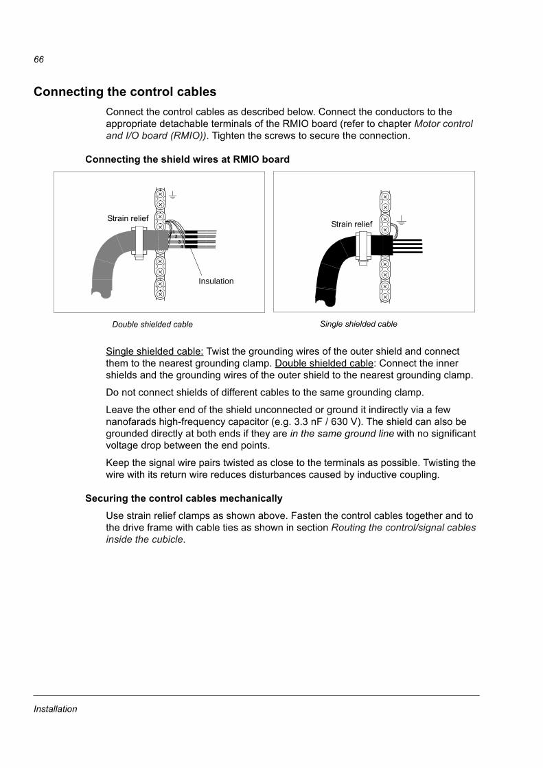
66
Connecting the control cablesConnect the control cables as described below. Connect the conductors to the appropriate detachable terminals of the RMIO board (refer to chapter Motor control and I/O board (RMIO)). Tighten the screws to secure the connection.
Connecting the shield wires at RMIO board
Single shielded cable: Twist the grounding wires of the outer shield and connect them to the nearest grounding clamp. Double shielded cable: Connect the inner shields and the grounding wires of the outer shield to the nearest grounding clamp.
Do not connect shields of different cables to the same grounding clamp.
Leave the other end of the shield unconnected or ground it indirectly via a few nanofarads high-frequency capacitor (e.g. 3.3 nF / 630 V). The shield can also be grounded directly at both ends if they are in the same ground line with no significant voltage drop between the end points.
Keep the signal wire pairs twisted as close to the terminals as possible. Twisting the wire with its return wire reduces disturbances caused by inductive coupling.
Securing the control cables mechanicallyUse strain relief clamps as shown above. Fasten the control cables together and to the drive frame with cable ties as shown in section Routing the control/signal cables inside the cubicle.
Double shielded cable Single shielded cable
Strain relief1
234
Insulation
Strain relief
Installation

67
Settings of the cooling fan transformer The voltage transformer of the cooling fan (T41) is located at the top of the drive module.
Setting of the auxiliary voltage transformer of the line contactor optionAdjust the setting of the transformer (T1, located in the enclosure extension) according to the input voltage.
Installation of optional modules and PCThe optional module (such as fieldbus adapter, I/O extension module and the pulse encoder interface) is inserted in the optional module slot of the RMIO board and fixed with two screws. See the appropriate optional module manual for cable connections.
Cabling of I/O and fieldbus modules
Set according to the supply voltage: 380 V, 400 V, 415 V, 440 V, 480 V or 500 V; or 525 V, 575 V, 600 V, 660 V or 690 V.Note: No need to set for 230 V units.
Set to 220 V if the supply frequency is 60 Hz. (The voltage is set to 230 V (50 Hz) at the factory.)
Shield
Module
234
1
As short as possible
Grounding wire of the outer shield
Strain relief witha cable tie
Alternative to a)
a)
Installation

68
Pulse encoder module cabling
Fibre optic link A DDCS fibre optic link is provided via the RDCO optional module for PC tools, master/follower link, NDIO, NTAC, NAIO, AIMA I/O module adapter and fieldbus adapter modules of type Nxxx. See RDCO User’s Manual [3AFE 64492209 (English)] for the connections. Observe colour coding when installing fibre optic cables. Blue connectors go to blue terminals, and grey connectors to grey terminals.
When installing multiple modules on the same channel, connect them in a ring.
Installation of user’s own relaysA motor thermistor relay can be installed to a rail in the pedestal (frame size R7) or on the lead-through plate (frame size R8), or to a DIN rail in the enclosure extension.
Installation of brake resistorsSee Resistor braking. Connect the resistor as shown in section Power cable connection diagram above.
Parameter settingsTo enable dynamic braking, certain drive parameters must be adjusted. For further information, refer to the Firmware Manual.
Strain reliefwith a cable tie
234
1
Clamp as close to the terminals as possible.
As short as possible
Note1: If the encoder is of unisolated type, ground the encoder cable at the drive end only. If the encoder is galvanically isolated from the motor shaft and the stator frame, ground the encoder cable shield at the drive and the encoder end.Note 2: Twist the pair cable wires.Note 3: The grounding wire of the outer shield of the cable can alternatively be connected to the SHLD terminal of the RTAC module.
6 5 4 3 2 16 5 4 3 2 1 8 7
08
4
C
26
A E
1
3579
B DF
CHASSIS
GND
NODE ID
SHLD
RTAC-01PULSE ENCO
DER INTERFACE
X2X1
WD/
INIT
CHB
CHASHLD
CHA+
CHA-
CHB+
CHB-
CHZ+
CHZ-
0 V0 VV OUT
+15V
V IN
+24V
a)
Alternative to a)
Installation

69
Motor control and I/O board (RMIO)
What this chapter containsThis chapter shows
• external control connections to the RMIO board for the ACS800 Standard Application Program (Factory Macro)
• specifications of the inputs and outputs of the board.
To which products this chapter appliesThis chapter applies to ACS800 units which employ the RMIO board.
Note for the ACS800-02 with enclosure extension and the ACS800-07The connections for the RMIO board shown below apply also to optional terminal block X2 available for the ACS800-02 and the ACS800-07. The terminals of the RMIO board are wired to terminal block X2 internally.
Terminals of X2 accept cables from 0.5 to 4.0 mm2 (22 to 12 AWG). Tightening torque: 0.4 to 0.8 Nm (0.3 to 0.6 lbf ft)
Note for external power supplyWARNING! If the RMIO board is supplied from an external power source, the loose end of the cable removed from the RMIO board terminal must be secured mechanically to a location where it cannot come into contact with electrical parts. If the screw terminal plug of the cable is removed, the wire ends must be individually insulated.
Motor control and I/O board (RMIO)
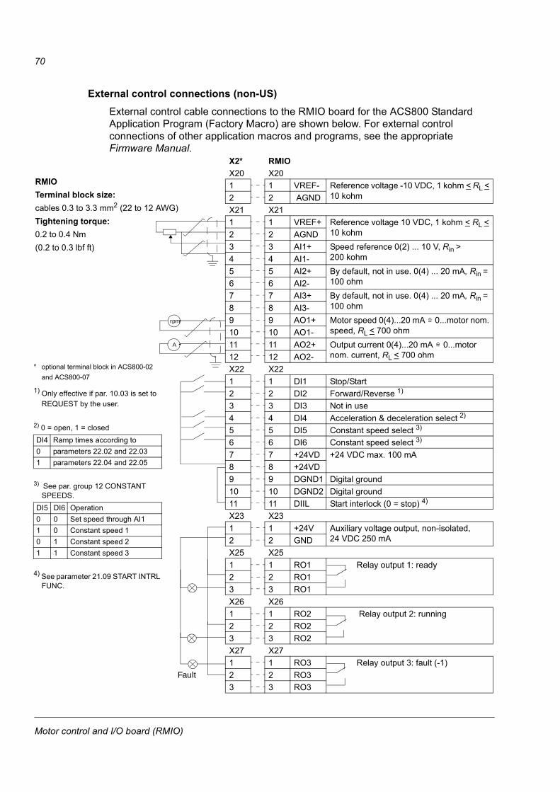
70
External control connections (non-US)External control cable connections to the RMIO board for the ACS800 Standard Application Program (Factory Macro) are shown below. For external control connections of other application macros and programs, see the appropriate Firmware Manual.
X2* RMIOX20 X201 1 VREF- Reference voltage -10 VDC, 1 kohm < RL <
10 kohm2 2 AGNDX21 X211 1 VREF+ Reference voltage 10 VDC, 1 kohm < RL <
10 kohm2 2 AGND3 3 AI1+ Speed reference 0(2) ... 10 V, Rin >
200 kohm4 4 AI1-5 5 AI2+ By default, not in use. 0(4) ... 20 mA, Rin =
100 ohm6 6 AI2-7 7 AI3+ By default, not in use. 0(4) ... 20 mA, Rin =
100 ohm8 8 AI3-9 9 AO1+ Motor speed 0(4)...20 mA 0...motor nom.
speed, RL < 700 ohm10 10 AO1-11 11 AO2+ Output current 0(4)...20 mA 0...motor
nom. current, RL < 700 ohm12 12 AO2-X22 X221 1 DI1 Stop/Start2 2 DI2 Forward/Reverse 1)
3 3 DI3 Not in use4 4 DI4 Acceleration & deceleration select 2)
5 5 DI5 Constant speed select 3)
6 6 DI6 Constant speed select 3)
7 7 +24VD +24 VDC max. 100 mA8 8 +24VD9 9 DGND1 Digital ground10 10 DGND2 Digital ground11 11 DIIL Start interlock (0 = stop) 4)
X23 X231 1 +24V Auxiliary voltage output, non-isolated,
24 VDC 250 mA2 2 GNDX25 X251 1 RO1 Relay output 1: ready2 2 RO13 3 RO1X26 X261 1 RO2 Relay output 2: running2 2 RO23 3 RO2X27 X271 1 RO3 Relay output 3: fault (-1)2 2 RO33 3 RO3
=
=
Fault
A
rpm
* optional terminal block in ACS800-02 and ACS800-07
1) Only effective if par. 10.03 is set to REQUEST by the user.
2) 0 = open, 1 = closed
3) See par. group 12 CONSTANT SPEEDS.
4) See parameter 21.09 START INTRL FUNC.
DI4 Ramp times according to0 parameters 22.02 and 22.031 parameters 22.04 and 22.05
DI5 DI6 Operation0 0 Set speed through AI11 0 Constant speed 10 1 Constant speed 21 1 Constant speed 3
RMIOTerminal block size: cables 0.3 to 3.3 mm2 (22 to 12 AWG) Tightening torque: 0.2 to 0.4 Nm (0.2 to 0.3 lbf ft)
Motor control and I/O board (RMIO)

71
External control connections (US)External control cable connections to the RMIO board for the ACS800 Standard Application Program (Factory Macro US version) are shown below. For external control connections of other application macros and programs, see the appropriate Firmware Manual.
X2* RMIOX20 X201 1 VREF- Reference voltage -10 VDC, 1 kohm < RL <
10 kohm2 2 AGNDX21 X211 1 VREF+ Reference voltage 10 VDC, 1 kohm < RL <
10 kohm2 2 AGND3 3 AI1+ Speed reference 0(2) ... 10 V, Rin >
200 kohm4 4 AI1-5 5 AI2+ By default, not in use. 0(4) ... 20 mA, Rin =
100 ohm6 6 AI2-7 7 AI3+ By default, not in use. 0(4) ... 20 mA, Rin =
100 ohm8 8 AI3-9 9 AO1+ Motor speed 0(4)...20 mA 0...motor nom.
speed, RL < 700 ohm10 10 AO1-11 11 AO2+ Output current 0(4)...20 mA 0...motor
nom. current, RL < 700 ohm12 12 AO2-X22 X221 1 DI1 Start ( )2 2 DI2 Stop ( )3 3 DI3 Forward/Reverse 1)
4 4 DI4 Acceleration & deceleration select 2)
5 5 DI5 Constant speed select 3)
6 6 DI6 Constant speed select 3)
7 7 +24VD +24 VDC max. 100 mA8 8 +24VD9 9 DGND1 Digital ground10 10 DGND2 Digital ground11 11 DIIL Start interlock (0 = stop) 4)
X23 X231 1 +24V Auxiliary voltage output, non-isolated,
24 VDC 250 mA2 2 GNDX25 X251 1 RO1 Relay output 1: ready2 2 RO13 3 RO1X26 X261 1 RO2 Relay output 2: running2 2 RO23 3 RO2X27 X271 1 RO3 Relay output 3: fault (-1)2 2 RO33 3 RO3
=
=
Fault
A
rpm
RMIOTerminal block size: cables 0.3 to 3.3 mm2 (22 to 12 AWG) Tightening torque: 0.2 to 0.4 Nm (0.2 to 0.3 lbf ft)
* optional terminal block in ACS800-U2 and ACS800-U7
1) Only effective if par. 10.03 is set to REQUEST by the user.
2) 0 = open, 1 = closed
3) See par. group 12 CONSTANT SPEEDS.
4) See parameter 21.09 START INTRL FUNC.
DI4 Ramp times according to0 parameters 22.02 and 22.031 parameters 22.04 and 22.05
DI5 DI6 Operation0 0 Set speed through AI11 0 Constant speed 10 1 Constant speed 21 1 Constant speed 3
Motor control and I/O board (RMIO)
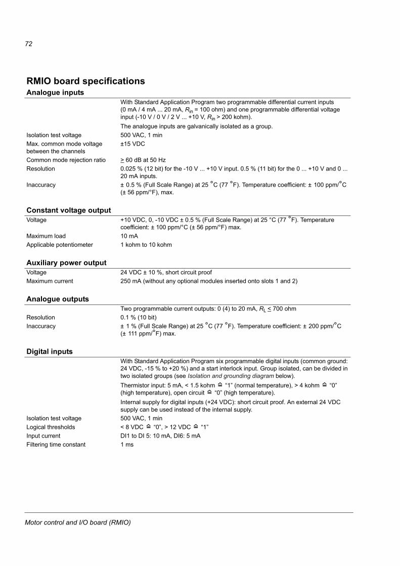
72
RMIO board specificationsAnalogue inputs
With Standard Application Program two programmable differential current inputs (0 mA / 4 mA ... 20 mA, Rin = 100 ohm) and one programmable differential voltage input (-10 V / 0 V / 2 V ... +10 V, Rin > 200 kohm).The analogue inputs are galvanically isolated as a group.
Isolation test voltage 500 VAC, 1 minMax. common mode voltage between the channels
±15 VDC
Common mode rejection ratio > 60 dB at 50 HzResolution 0.025 % (12 bit) for the -10 V ... +10 V input. 0.5 % (11 bit) for the 0 ... +10 V and 0 ...
20 mA inputs.Inaccuracy ± 0.5 % (Full Scale Range) at 25 °C (77 °F). Temperature coefficient: ± 100 ppm/°C
(± 56 ppm/°F), max.
Constant voltage outputVoltage +10 VDC, 0, -10 VDC ± 0.5 % (Full Scale Range) at 25 °C (77 °F). Temperature
coefficient: ± 100 ppm/°C (± 56 ppm/°F) max.Maximum load 10 mAApplicable potentiometer 1 kohm to 10 kohm
Auxiliary power outputVoltage 24 VDC ± 10 %, short circuit proofMaximum current 250 mA (without any optional modules inserted onto slots 1 and 2)
Analogue outputsTwo programmable current outputs: 0 (4) to 20 mA, RL < 700 ohm
Resolution 0.1 % (10 bit)Inaccuracy ± 1 % (Full Scale Range) at 25 °C (77 °F). Temperature coefficient: ± 200 ppm/°C
(± 111 ppm/°F) max.
Digital inputsWith Standard Application Program six programmable digital inputs (common ground: 24 VDC, -15 % to +20 %) and a start interlock input. Group isolated, can be divided in two isolated groups (see Isolation and grounding diagram below).Thermistor input: 5 mA, < 1.5 kohm “1” (normal temperature), > 4 kohm “0” (high temperature), open circuit “0” (high temperature).Internal supply for digital inputs (+24 VDC): short circuit proof. An external 24 VDC supply can be used instead of the internal supply.
Isolation test voltage 500 VAC, 1 minLogical thresholds < 8 VDC “0”, > 12 VDC “1”Input current DI1 to DI 5: 10 mA, DI6: 5 mAFiltering time constant 1 ms
Motor control and I/O board (RMIO)

73
Relay outputsThree programmable relay outputs
Switching capacity 8 A at 24 VDC or 250 VAC, 0.4 A at 120 VDCMinimum continuous current 5 mA rms at 24 VDCMaximum continuous current 2 A rmsIsolation test voltage 4 kVAC, 1 minute
DDCS fibre optic linkWith optional communication adapter module RDCO. Protocol: DDCS (ABB Distributed Drives Communication System)
24 VDC power inputVoltage 24 VDC ± 10 %Typical current consumption (without optional modules)
250 mA
Maximum current consumption 1200 mA (with optional modules inserted)
The terminals on the RMIO board as well as on the optional modules attachable to the board fulfil the Protective Extra Low Voltage (PELV) requirements stated in EN 50178 provided that the external circuits connected to the terminals also fulfil the requirements.
Motor control and I/O board (RMIO)

74
Isolation and grounding diagram
X201 VREF-2 AGND
X211 VREF+2 AGND3 AI1+4 AI1-5 AI2+6 AI2-7 AI3+8 AI3-
9 AO1+10 AO1-11 AO2+12 AO2-X221 DI12 DI23 DI34 DI4
9 DGND1
5 DI56 DI67 +24VD8 +24VD
11 DIIL
10 DGND2X231 +24 V2 GNDX251 RO12 RO13 RO1X261 RO22 RO23 RO2X271 RO32 RO33 RO3
Common mode voltage between channels ±15 V
J1
(Test voltage: 500 V AC)
or
Jumper J1 settings:
All digital inputs share a common ground. This is the default setting.
Grounds of input groups DI1…DI4 and DI5/DI6/DIIL are separate (isolation voltage 50 V).
Ground
(Test voltage: 4 kV AC)
Motor control and I/O board (RMIO)

75
Installation checklist
ChecklistCheck the mechanical and electrical installation of the drive before start-up. Go through the checklist below together with another person. Read the Safety instructions on the first pages of this manual before you work on the unit.
Check
MECHANICAL INSTALLATION
The ambient operating conditions are allowed. See Installation, Technical data: IEC ratings or US tables / NEMA ratings, Ambient conditions.
The unit is fixed properly on floor and a vertical non-flammable wall. See Installation.
The cooling air will flow freely.
ELECTRICAL INSTALLATION See Planning the electrical installation, Installation.
The motor and the driven equipment are ready for start. See Planning the electrical installation: Checking the compatibility of the motor, Technical data: Motor connection.
The +E202 EMC filter capacitors are disconnected if the drive is connected to an IT (ungrounded) system.
The capacitors are reformed if stored over one year (refer to ACS 600/800 Capacitor Reforming Guide [64059629 (English)].
The drive is grounded properly.
The mains (input power) voltage matches the drive nominal input voltage.
The mains (input power) connections at U1, V1 and W1 and their tightening torques are OK.
Appropriate mains (input power) fuses and disconnector are installed.
The motor connections at U2, V2 and W2 and their tightening torques are OK.
The motor cable is routed away from other cables.
Setting of the fan voltage tranformer
Setting of the auxiliary voltage transformer (option +G304)
There are no power factor compensation capacitors in the motor cable.
The external control connections inside the drive are OK.
There are no tools, foreign objects or dust from drilling inside the drive.
Mains (input power) voltage cannot be applied to the output of the drive (with bypass connection).
Drive, motor connection box and other covers are in place.
Installation checklist

76
Installation checklist

77
Maintenance
What this chapter containsThis chapter contains preventive maintenance instructions.
Safety
WARNING! Read the Safety instructions on the first pages of this manual before performing any maintenance on the equipment. Ignoring the safety instructions can cause injury or death. Note: There are parts carrying dangerous voltages near the RMIO board when the drive is powered.
Maintenance intervalsIf installed in an appropriate environment, the drive requires very little maintenance. This table lists the routine maintenance intervals recommended by ABB.
Interval Maintenance Instruction
Every year when stored Capacitor reforming See Reforming.
Every 6 to 12 months (depending on the dustiness of the environment)
Heatsink temperature check and cleaning
See Heatsink.
Every 7 years Cooling fan change See Fan.
Every 10 years Capacitor change See Capacitors.
Every 5 years Enclosure extension cooling fan change (with contactor option)
See Replacing the fan of the enclosure extension
Maintenance

78
LayoutThe layout stickers of the drive are shown below. The stickers show all possible components. Not all of them are present in each delivery or described here.
Designation Component
A49 Control panelA41 Motor control and I/O board (RMIO)
Y41 Cooling fanC_ Capacitors
Code: 64572261-B Code: 64601423-B
R7 R8
Maintenance

79
HeatsinkThe heatsink fins pick up dust from the cooling air. The drive runs into overtemperature warnings and faults if the heatsink is not clean. In a “normal” environment (not dusty, not clean) the heatsink should be checked annually, in a dusty environment more often.
Clean the heatsink as follows (when necessary):
1. Remove the cooling fan (see section Fan).
2. Blow dry clean compressed air from bottom to top and simultaneously use a vacuum cleaner at the air outlet to trap the dust. Note: Prevent dust from entering adjoining equipment.
3. Replace the cooling fan.
FanThe lifespan of the cooling fan of the drive is about 50 000 (R7) and 60 000 (R8) hours. The actual lifespan depends on the running time of the fan, ambient temperature and dust concentration. See the appropriate ACS800 firmware manual for the actual signal which indicates the running time of the cooling fan.
A cooling fan is included in the enclosure extension with a contactor option. Its lifespan is at least 40 000 h.
Replacement fans are available from ABB. Do not use other than ABB specified spare parts.
Maintenance

80
Replacing the fan of the enclosure extensionThe fan is fastened to the inside of the roof.
Remove the fan as follows:
1. Disconnect the fan wires.
2. Loosen the six fixing screws of the fan cassette.
3. Shift the fan cassette sideways and pull it out of the enclosure extension.
4. Undo the screws that fasten the fan to the base of the cassette.
5. Undo the screws that fasten the fingerguard.
6. Install the new fan in reverse order to the above.
4
2
2 22
22
44
1
Views from belowFront side in frame size R7 units
3
55 5
5
4
Fron
t sid
e in
fram
e si
ze R
8 un
its
64669800-C
Maintenance

81
Replacing the fan (R7)1. Remove the upper front cover and disconnect the control panel cables.
2. Disconnect the discharging resistor wire.
3. Remove the DC capacitor pack by undoing the red fixing screws and pulling the pack out.
4. Disconnect the fan supply wires (detachable connector).
5. Disconnect the fan capacitor wires and remove the fan capacitor.
6. Disconnect the AINP board wires from connectors X1 and X2.
7. Undo the red fixing screws of the fan cassette.
8. Press the snap-on holders to release the side cover.
9. Lift the handle and pull the fan cassette out.
10. Install the new fan and fan capacitor in reverse order to the above.
3
3
3
3
47
7
8
8
9
2
DC-DC+
5
3
3
3
6
Maintenance

82
Replacing the fan (R8)1. Remove the front covers by undoing the fixing screws and disconnecting the
control panel cable.
2. Disconnect the fan capacitor and power supply wires.
3. Remove the fan capacitor.
4. Units without enclosure extension: disconnect the power supply (a), fibre optic (b) and control panel (c) cables from the RMIO board.Units with enclosure extension: move the wires in front of the fan aside.
5. Undo the red fastening screws of the plastic side cover of the fan. Shift the cover to the right to free its right-hand edge and lift the cover off.
6. Undo the red fastening screws of the fan.
7. Lift the fan out.
8. Install the new fan and fan capacitor in reverse order to the above.
2
6
6
7
5
5
2
4a
4b
4c
3
Maintenance

83
CapacitorsThe drive intermediate circuit employs several electrolytic capacitors. Their lifespan is at least 90 000 hours depending on the operating time of the drive, loading and ambient temperature. Capacitor life can be prolonged by lowering the ambient temperature.
It is not possible to predict a capacitor failure. Capacitor failure is usually followed by damage to the unit and an input cable fuse failure, or a fault trip. Contact ABB if capacitor failure is suspected. Replacements are available from ABB. Do not use other than ABB specified spare parts.
ReformingReform (re-age) spare part capacitors once a year according to ACS 600/800 Capacitor Reforming Guide [code: 64059629 (English)].
Replacing the capacitor pack (R7)Replace the capacitor pack as described in section Replacing the fan (R7).
Maintenance
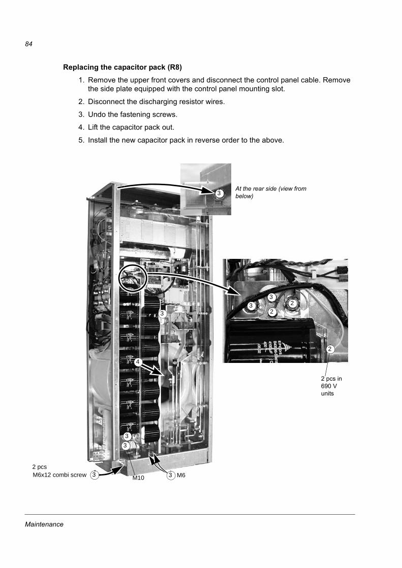
84
Replacing the capacitor pack (R8)1. Remove the upper front covers and disconnect the control panel cable. Remove
the side plate equipped with the control panel mounting slot.
2. Disconnect the discharging resistor wires.
3. Undo the fastening screws.
4. Lift the capacitor pack out.
5. Install the new capacitor pack in reverse order to the above.
33
22
M10 M62 pcsM6x12 combi screw
3
3
3
3 3
4
At the rear side (view from below)
2 pcs in 690 V units
2
3
Maintenance
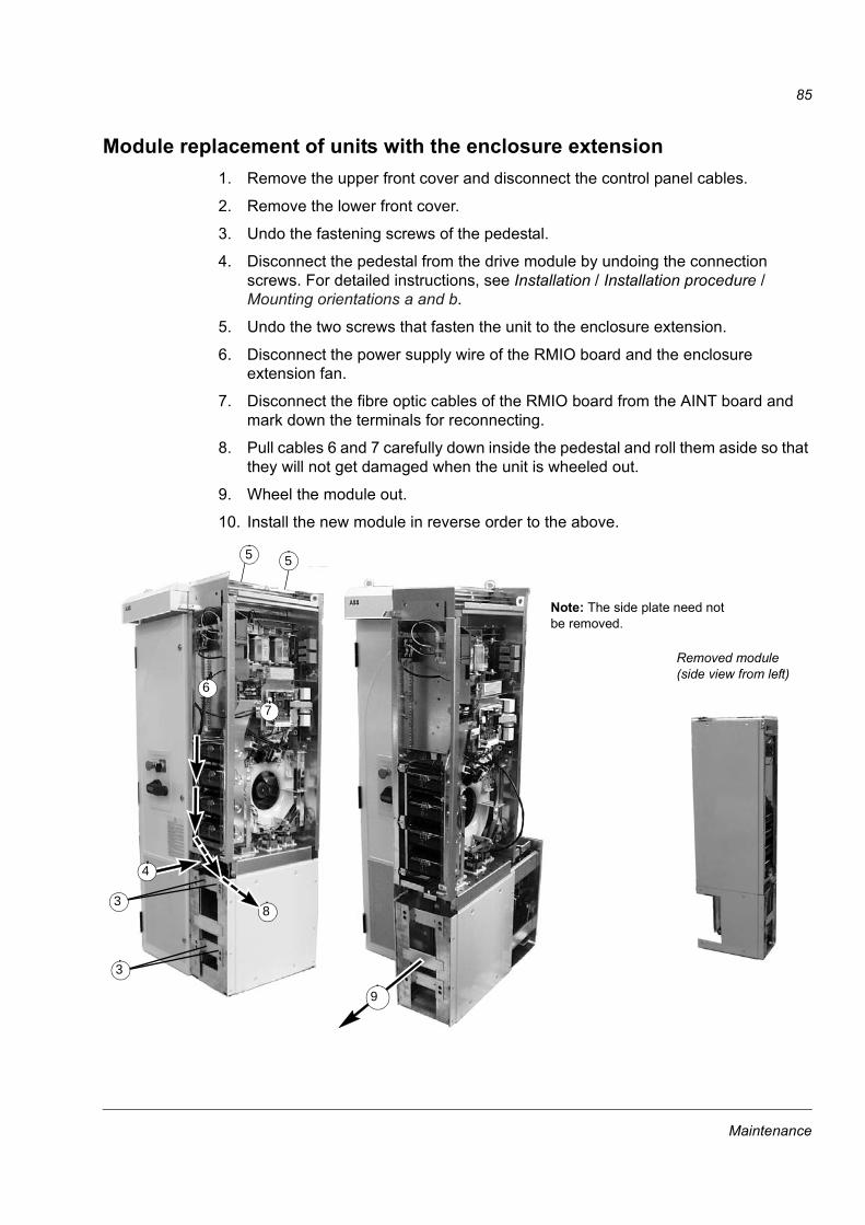
85
Module replacement of units with the enclosure extension1. Remove the upper front cover and disconnect the control panel cables.
2. Remove the lower front cover.
3. Undo the fastening screws of the pedestal.
4. Disconnect the pedestal from the drive module by undoing the connection screws. For detailed instructions, see Installation / Installation procedure / Mounting orientations a and b.
5. Undo the two screws that fasten the unit to the enclosure extension.
6. Disconnect the power supply wire of the RMIO board and the enclosure extension fan.
7. Disconnect the fibre optic cables of the RMIO board from the AINT board and mark down the terminals for reconnecting.
8. Pull cables 6 and 7 carefully down inside the pedestal and roll them aside so that they will not get damaged when the unit is wheeled out.
9. Wheel the module out.
10. Install the new module in reverse order to the above.
Removed module (side view from left)
6
7
83
3
55
Note: The side plate need not be removed.
9
4
Maintenance

86
LEDsThis table describes LEDs of the drive.
Where LED When the LED is lit
RMIO board Red Drive in fault state
Green The power supply on the board is OK.
Control panel mounting platform Red Drive in fault state
Green The main + 24 V power supply for the control panel and the RMIO board is OK.
AINT board V204 (green) +5 V voltage of the board is OK.
V309 (red) Prevention of unexpected start is ON.
V310 (green) IGBT control signal transmission to the gate driver control boards is enabled.
Maintenance
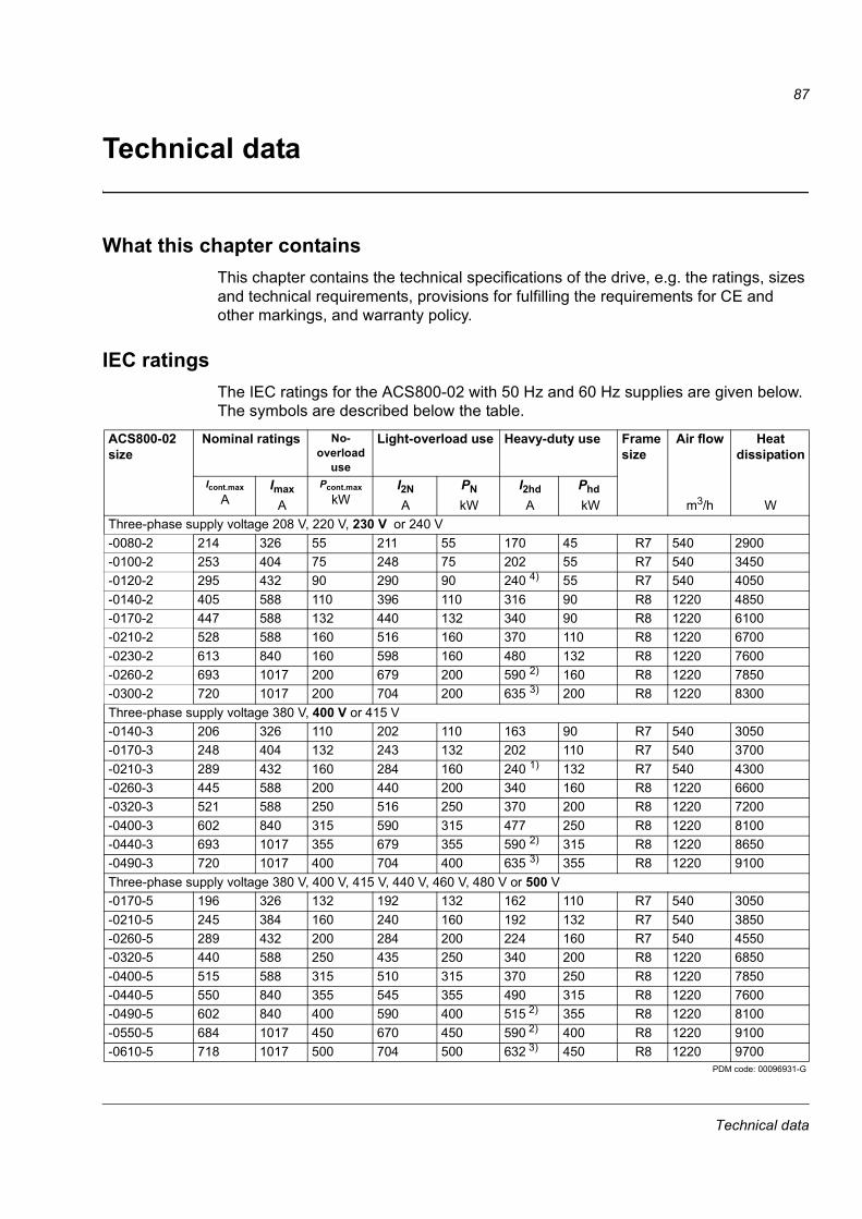
87
Technical data
What this chapter containsThis chapter contains the technical specifications of the drive, e.g. the ratings, sizes and technical requirements, provisions for fulfilling the requirements for CE and other markings, and warranty policy.
IEC ratingsThe IEC ratings for the ACS800-02 with 50 Hz and 60 Hz supplies are given below. The symbols are described below the table.
ACS800-02 size
Nominal ratings No- overload
use
Light-overload use Heavy-duty use Frame size
Air flow Heat dissipation
Icont.maxA
ImaxA
Pcont.maxkW
I2NA
PNkW
I2hdA
Phd kW m3/h W
Three-phase supply voltage 208 V, 220 V, 230 V or 240 V-0080-2 214 326 55 211 55 170 45 R7 540 2900-0100-2 253 404 75 248 75 202 55 R7 540 3450-0120-2 295 432 90 290 90 240 4) 55 R7 540 4050-0140-2 405 588 110 396 110 316 90 R8 1220 4850-0170-2 447 588 132 440 132 340 90 R8 1220 6100-0210-2 528 588 160 516 160 370 110 R8 1220 6700-0230-2 613 840 160 598 160 480 132 R8 1220 7600-0260-2 693 1017 200 679 200 590 2) 160 R8 1220 7850-0300-2 720 1017 200 704 200 635 3) 200 R8 1220 8300Three-phase supply voltage 380 V, 400 V or 415 V -0140-3 206 326 110 202 110 163 90 R7 540 3050-0170-3 248 404 132 243 132 202 110 R7 540 3700-0210-3 289 432 160 284 160 240 1) 132 R7 540 4300-0260-3 445 588 200 440 200 340 160 R8 1220 6600-0320-3 521 588 250 516 250 370 200 R8 1220 7200-0400-3 602 840 315 590 315 477 250 R8 1220 8100-0440-3 693 1017 355 679 355 590 2) 315 R8 1220 8650-0490-3 720 1017 400 704 400 635 3) 355 R8 1220 9100Three-phase supply voltage 380 V, 400 V, 415 V, 440 V, 460 V, 480 V or 500 V -0170-5 196 326 132 192 132 162 110 R7 540 3050-0210-5 245 384 160 240 160 192 132 R7 540 3850-0260-5 289 432 200 284 200 224 160 R7 540 4550-0320-5 440 588 250 435 250 340 200 R8 1220 6850-0400-5 515 588 315 510 315 370 250 R8 1220 7850-0440-5 550 840 355 545 355 490 315 R8 1220 7600-0490-5 602 840 400 590 400 515 2) 355 R8 1220 8100-0550-5 684 1017 450 670 450 590 2) 400 R8 1220 9100-0610-5 718 1017 500 704 500 632 3) 450 R8 1220 9700
PDM code: 00096931-G
Technical data

88
1) 50 % overload is available for one minute every 5 minutes if ambient temperature is less than 25 °C. If ambient temperature is 40 °C, max. available overload is 37 %.
2) 50 % overload is available for one minute every 5 minutes if ambient temperature is less than 30 °C. If ambient temperature is 40 °C, max. available overload is 40 %.
3) 50 % overload is available one minute every 5 minutes if ambient temperature is less than 20 °C. If ambient temperature is 40 °C, max. available overload is 30 %.
4) 50 % overload is available one minute every 5 minutes if ambient temperature is less than 35 °C. If ambient temperature is 40 °C, max. available overload is 45 %.
Symbols
SizingThe current ratings are the same regardless of the supply voltage within one voltage range. To achieve the rated motor power given in the table, the rated current of the drive must be higher than or equal to the rated motor current.Note 1: The maximum allowed motor shaft power is limited to 1.5 · Phd. If the limit is exceeded, motor torque and current are automatically restricted. The function protects the input bridge of the drive against overload.Note 2: The ratings apply in ambient temperature of 40 °C (104 °F). In lower temperatures the ratings are higher (except Imax).Note 3: Use the DriveSize PC tool for a more accurate dimensioning if the ambient temperature is below 40 °C (104 °F) or the drive is loaded cyclically.
Nominal ratingsIcont.max continuous rms output current. No overload capability at 40 °C. Imax maximum output current. Available for 10 s at start, otherwise as long as allowed by drive
temperature. Typical ratings:No-overload usePcont.max typical motor power. The power ratings apply to most IEC 34 motors at the nominal voltage,
230 V, 400 V or 500 V.Light-overload use (10 % overload capability)I2N continuous rms current. 10 % overload is allowed for one minute every 5 minutes. PN typical motor power. The power ratings apply to most IEC 34 motors at the nominal voltage,
230 V, 400 V or 500 V. Heavy-duty use (50 % overload capability)I2hd continuous rms current. 50 % overload is allowed for one minute every 5 minutes.Phd typical motor power. The power ratings apply to most IEC 34 motors at the nominal voltage,
230 V, 400 V or 500 V.
Technical data

89
DeratingThe load capacity (current and power) decreases if the installation site altitude exceeds 1000 metres (3281 ft), or if the ambient temperature exceeds 40 °C (104 °F).
Temperature deratingIn the temperature range +40 °C (+104 °F) to +50 °C (+122 °F), the rated output current is decreased 1 % for every additional 1 °C (1.8 °F). The output current is calculated by multiplying the current given in the rating table by the derating factor. Example If the ambient temperature is 50 °C (+122 °F), the derating factor is 100 % - 1 · 10 °C = 90 % or 0.90. The output current is then 0.90 · I2N , 0.90 · I2hd or 0.90 · Icont.max.
Altitude deratingAt altitudes from 1000 to 4000 m (3281 to 13123 ft) above sea level, the derating is 1 % for every 100 m (328 ft). For a more accurate derating, use the DriveSize PC tool. If the installation site is higher than 2000 m (6562 ft) above sea level, please contact your local ABB distributor or office for further information.
%°C
Technical data

90
Mains cable fusesFuses for short-circuit protection of the mains cable are listed below. The fuses also protect the adjoining equipment of the drive in case of a short-circuit. Check that the operating time of the fuse is below 0.5 seconds. The operating time depends on the supply network impedance and the cross-sectional area, material and length of the supply cable. See also Planning the electrical installation: Thermal overload and short-circuit protection. For UL recognized fuses, see US tables. Note 1: In multicable installations, install only one fuse per phase (not one fuse per conductor). Note 2: Larger fuses must not be used.Note 3: Fuses from other manufacturers can be used if they meet the ratings.
Standard gG fuses ACS800-02 size
Input current
Fuse
A A A2s V Manufacturer Type IEC sizeThree-phase supply voltage 208 V, 220 V, 230 V or 240 V-0080-2 201 250 550 000 500 ABB Control OFAF1H250 1-0100-2 239 315 1 100 000 500 ABB Control OFAF2H315 2-0120-2 285 315 1 100 000 500 ABB Control OFAF2H315 2-0140-2 391 500 2 900 000 500 ABB Control OFAF3H500 3-0170-2 428 500 2 900 000 500 ABB Control OFAF3H500 3-0210-2 506 630 4 000 000 500 ABB Control OFAF3H630 3-0230-2 599 630 4 000 000 500 ABB Control OFAF3H630 3-0260-2 677 800 7 400 000 500 ABB Control OFAF3H800 3-0300-2 707 800 7 400 000 500 ABB Control OFAF3H800 3Three-phase supply voltage 380 V, 400 V or 415 V -0140-3 196 250 550 000 500 ABB Control OFAF1H250 1-0170-3 237 315 1 100 000 500 ABB Control OFAF2H315 2-0210-3 286 315 1 100 000 500 ABB Control OFAF2H315 2-0260-3 438 500 2 900 000 500 ABB Control OFAF3H500 3-0320-3 501 630 4 000 000 500 ABB Control OFAF3H630 3-0400-3 581 630 4 000 000 500 ABB Control OFAF3H630 3-0440-3 674 800 7 400 000 500 ABB Control OFAF3H800 3-0490-3 705 800 7 400 000 500 ABB Control OFAF3H800 3Three-phase supply voltage 380 V, 400 V, 415 V, 440 V, 460 V, 480 V or 500 V -0170-5 191 250 550 000 500 ABB Control OFAF1H250 1-0210-5 243 315 1 100 000 500 ABB Control OFAF2H315 2-0260-5 291 315 1 100 000 500 ABB Control OFAF2H315 2-0320-5 424 500 2 900 000 500 ABB Control OFAF3H500 3-0400-5 498 630 4 000 000 500 ABB Control OFAF3H630 3-0440-5 543 630 4 000 000 500 ABB Control OFAF3H630 3-0490-5 590 630 4 000 000 500 ABB Control OFAF3H630 3-0550-5 669 800 7 400 000 500 ABB Control OFAF3H800 3-0610-5 702 800 7 400 000 500 ABB Control OFAF3H800 3
PDM code: 00096931-G
Technical data

91
Ultrarapid (aR) fuses
A2s value for -7 units at 660 V
ACS800-02 size
Input current
A
FuseA A2s V Manufacturer Type DIN 43620 Size
Three-phase supply voltage 208 V, 220 V, 230 V or 240 V-0080-2 201 400 105 000 690 Bussmann 170M3819 DIN1*-0100-2 239 500 145 000 690 Bussmann 170M5810 DIN2*-0120-2 285 550 190 000 690 Bussmann 170M5811 DIN2*-0140-2 391 800 465 000 690 Bussmann 170M6812 DIN3-0170-2 428 800 465 000 690 Bussmann 170M6812 DIN3-0210-2 506 1000 945 000 690 Bussmann 170M6814 DIN3-0230-2 599 1250 1 950 000 690 Bussmann 170M8554 DIN3-0260-2 677 1600 3 900 000 690 Bussmann 170M8557 DIN3-0300-2 707 1600 3 900 000 690 Bussmann 170M8557 DIN3Three-phase supply voltage 380 V, 400 V or 415 V -0140-3 196 400 105 000 690 Bussmann 170M3819 DIN1*-0170-3 237 500 145 000 690 Bussmann 170M5810 DIN2*-0210-3 286 550 190 000 690 Bussmann 170M5811 DIN2*-0260-3 438 800 465 000 690 Bussmann 170M6812 DIN3-0320-3 501 1000 945 000 690 Bussmann 170M6814 DIN3-0400-3 581 1250 1 950 000 690 Bussmann 170M8554 DIN3-0440-3 674 1600 3 900 000 690 Bussmann 170M8557 DIN3-0490-3 705 1600 3 900 000 690 Bussmann 170M8557 DIN3Three-phase supply voltage 380 V, 400 V, 415 V, 440 V, 460 V, 480 V or 500 V -0170-5 191 400 105 000 690 Bussmann 170M3819 DIN1*-0210-5 243 500 145 000 690 Bussmann 170M5810 DIN2*-0260-5 291 550 190 000 690 Bussmann 170M5811 DIN2*-0320-5 424 800 465 000 690 Bussmann 170M6812 DIN3-0400-5 498 1000 945 000 690 Bussmann 170M6814 DIN3-0440-5 543 1250 1 950 000 690 Bussmann 170M8554 DIN3-0490-5 590 1250 1 950 000 690 Bussmann 170M8554 DIN3-0550-5 669 1600 3 900 000 690 Bussmann 170M8557 DIN3-0610-5 702 1600 3 900 000 690 Bussmann 170M8557 DIN3
PDM code: 00096931-G
Technical data

92
Cable typesThe table below gives copper and aluminium cable types for different load currents. Cable sizing is based on max. 9 cables laid on a cable ladder side by side, ambient temperature 30 °C, PVC insulation, surface temperature 70 °C (EN 60204-1 and IEC 60364-5-2/2001). For other conditions, size the cables according to local safety regulations, appropriate input voltage and the load current of the drive.
Copper cables with concentric copper shield
Aluminium cables with concentric copper shield
Max. load current
A
Cable type
mm2
Max. load current
A
Cable type
mm2
62 3x16 61 3x2579 3x25 75 3x3598 3x35 91 3x50119 3x50 117 3x70153 3x70 143 3x95186 3x95 165 3x120215 3x120 191 3x150249 3x150 218 3x185284 3x185 257 3x240335 3x240 274 3 x (3x50)358 3 x (3x50) 285 2 x (3x95)371 2 x (3x95) 331 2 x (3x120)431 2 x (3x120) 351 3 x (3x70)459 3 x (3x70) 382 2 x (3x150)498 2 x (3x150) 428 3 x (3x95)557 3 x (3x95) 437 2 x (3x185)568 2 x (3x185) 496 3 x (3x120)646 3 x (3x120) 515 2 x (3x240)671 2 x (3x240) 573 3 x (3x150)746 3 x (3x150) 655 3 x (3x185)852 3 x (3x185) 772 3 x (3x240)1006 3 x (3x240)
PDM code: 00096931-E
Technical data
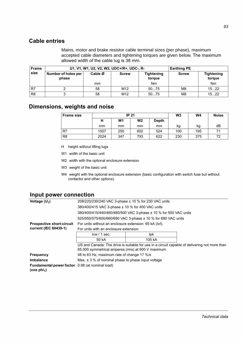
93
Cable entriesMains, motor and brake resistor cable terminal sizes (per phase), maximum accepted cable diameters and tightening torques are given below. The maximum allowed width of the cable lug is 38 mm.
Dimensions, weights and noise
H height without lifting lugs
W1 width of the basic unit
W2 width with the optional enclosure extension
W3 weight of the basic unit
W4 weight with the optional enclosure extension (basic configuration with switch fuse but without contactor and other options).
Frame size
U1, V1, W1, U2, V2, W2, UDC+/R+, UDC-, R- Earthing PE Number of holes per
phaseCable Ø Screw Tightening
torqueScrew Tightening
torquemm Nm Nm
R7 2 58 M12 50...75 M8 15...22R8 3 58 M12 50...75 M8 15...22
Frame size IP 21 W3 W4 NoiseH W1 W2 Depth
mm mm mm mm kg kg dBR7 1507 250 602 524 100 195 71R8 2024 347 793 622 230 375 72
Input power connectionVoltage (U1) 208/220/230/240 VAC 3-phase ± 10 % for 230 VAC units
380/400/415 VAC 3-phase ± 10 % for 400 VAC units 380/400/415/440/460/480/500 VAC 3-phase ± 10 % for 500 VAC units525/550/575/600/660/690 VAC 3-phase ± 10 % for 690 VAC units
Prospective short-circuit current (IEC 60439-1)
For units without an enclosure extension: 65 kA (Icf).For units with an enclosure extension:
Icw / 1 sec. Ipk50 kA 105 kA
US and Canada: The drive is suitable for use in a circuit capable of delivering not more than 65,000 symmetrical amperes (rms) at 600 V maximum.
Frequency 48 to 63 Hz, maximum rate of change 17 %/sImbalance Max. ± 3 % of nominal phase to phase input voltageFundamental power factor (cos phi1)
0.98 (at nominal load)
Technical data

94
Motor connectionVoltage (U2) 0 to U1, 3-phase symmetrical, Umax at the field weakening pointFrequency DTC mode: 0 to 3.2 · fFWP. Maximum frequency 300 Hz.
fFWP =
fFWP: frequency at field weakening point; UNmains: mains (input power) voltage; UNmotor: rated motor voltage; fNmotor: rated motor frequency
Frequency resolution 0.01 HzCurrent See section IEC ratings.Power limit 1.5 · PhdField weakening point 8 to 300 HzSwitching frequency 3 kHz (average). In 690 V units 2 kHz (average).Maximum recommended motor cable length
Type code (EMC equipment) Max. motor cable lengthDTC control Scalar control
- 300 m (984 ft) 300 m (984 ft)+E202 *, +E210 * 100 m (328 ft) 100 m (328 ft)* Motor cable longer than 100 m (328 ft) is allowed but then the EMC Directive requirements may not be fulfilled.
EfficiencyApproximately 98 % at nominal power level
CoolingMethod Internal fan, flow direction from front to top Free space around the unit
See chapter Installation.
Cooling air flow See IEC ratings.
Degrees of protectionIP 21 (UL type 1)
UNmains
UNmotor· fNmotor
Technical data

95
Ambient conditionsEnvironmental limits for the drive are given below. The drive is to be used in a heated, indoor, controlled environment.
Operation installed for stationary use
Storagein the protective package
Transportationin the protective package
Installation site altitude 0 to 4000 m (13123 ft) above sea level [above 1000 m (3281 ft), see section Derating]
- -
Air temperature -15 to +50 °C (5 to 122 °F). See section Derating.
-40 to +70 °C (-40 to +158 °F) -40 to +70 °C (-40 to +158 °F)
Relative humidity 5 to 95% Max. 95% Max. 95%No condensation allowed. Maximum allowed relative humidity is 60% in the presence of corrosive gases.
Contamination levels (IEC 60721-3-3, IEC 60721-3-2, IEC 60721-3-1)
No conductive dust allowed.Boards without coating: Chemical gases: Class 3C1Solid particles: Class 3S2Boards with coating: Chemical gases: Class 3C2Solid particles: Class 3S2
Boards without coating: Chemical gases: Class 1C2Solid particles: Class 1S3Boards with coating: Chemical gases: Class 1C2Solid particles: Class 1S3
Boards without coating: Chemical gases: Class 2C2Solid particles: Class 2S2Boards with coating: Chemical gases: Class 2C2Solid particles: Class 2S2
Atmospheric pressure 70 to 106 kPa0.7 to 1.05 atmospheres
70 to 106 kPa0.7 to 1.05 atmospheres
60 to 106 kPa0.6 to 1.05 atmospheres
Vibration (IEC 60068-2) Max. 1 mm (0.04 in.)(5 to 13.2 Hz),max. 7 m/s2 (23 ft/s2)(13.2 to 100 Hz) sinusoidal
Max. 1 mm (0.04 in.)(5 to 13.2 Hz),max. 7 m/s2 (23 ft/s2)(13.2 to 100 Hz) sinusoidal
Max. 3.5 mm (0.14 in.)(2 to 9 Hz), max. 15 m/s2 (49 ft/s2)(9 to 200 Hz) sinusoidal
Shock (IEC 60068-2-29) Not allowed Max. 100 m/s2 (330 ft./s2), 11 ms
Max. 100 m/s2 (330 ft./s2), 11 ms
Free fall Not allowed 100 mm (4 in.) for weight over 100 kg (220 lb)
100 mm (4 in.) for weight over 100 kg (220 lb)
Technical data

96
MaterialsDrive enclosure • PC/ABS 2.5 mm, colour NCS 1502-Y (RAL 90021 / PMS 420 C)
• hot-dip zinc coated steel sheet 1.5 to 2.5 mm, thickness of coating 100 micrometres, colour NCS 1502-Y
Package plywood and wood. Plastic covering of the package: PE-LD, bands PP or steel.Disposal The drive contains raw materials that should be recycled to preserve energy and natural
resources. The package materials are environmentally compatible and recyclable. All metal parts can be recycled. The plastic parts can either be recycled or burned under controlled circumstances, according to local regulations. Most recyclable parts are marked with recycling marks.If recycling is not feasible, all parts excluding electrolytic capacitors and printed circuit boards can be landfilled. The DC capacitors (C1-1 to C1-x) contain electrolyte and the printed circuit boards contain lead, both of which will be classified as hazardous waste within the EU. They must be removed and handled according to local regulations. For further information on environmental aspects and more detailed recycling instructions, please contact your local ABB distributor.
Applicable standardsThe drive complies with the following standards. The compliance with the European Low Voltage Directive is verified according to standards EN 50178 and EN 60204-1.
• EN 50178 (1997) Electronic equipment for use in power installations• EN 60204-1 (1997) Safety of machinery. Electrical equipment of machines. Part 1: General requirements.
Provisions for compliance: The final assembler of the machine is responsible for installing - an emergency-stop device - a supply disconnecting device.
• EN 60529: 1991 (IEC 529)
Degrees of protection provided by enclosures (IP code)
• IEC 60664-1 (1992) Insulation coordination for equipment within low-voltage systems. Part 1: Principles, requirements and tests.
• EN 61800-3 (1996) + Amendment A11 (2000)
EMC product standard including specific test methods
• UL 508C UL Standard for Safety, Power Conversion Equipment, second edition• CSA C22.2 No. 14-95 Industrial control equipment
Technical data

97
CE markingA CE mark is attached to the drive to verify that the unit follows the provisions of the European Low Voltage and EMC Directives (Directive 73/23/EEC, as amended by 93/68/EEC and Directive 89/336/EEC, as amended by 93/68/EEC).
DefinitionsEMC stands for Electromagnetic Compatibility. It is the ability of electrical/electronic equipment to operate without problems within an electromagnetic environment. Likewise, the equipment must not disturb or interfere with any other product or system within its locality.The EMC Directive defines the requirements for immunity and emissions of electrical equipment used within the European Union. The EMC product standard [EN 61800-3 + Amendment A11 (2000)] covers requirements stated for drives. First environment includes establishments connected to a low-voltage network which supplies buildings used for domestic purposes. Second environment includes establishments connected to a network not supplying domestic premises. Restricted distribution: mode of sales distribution in which the manufacturer restricts the supply of equipment to suppliers, customers or users who separately or jointly have technical competence in the EMC requirements of the application of drives.
Unrestricted distribution: mode of sales distribution in which the supply of equipment is not dependent on the EMC competence of the customer or user for the application of drives.
Compliance with the EMC DirectiveFirst environment
The requirements of the EMC Directive can be met as follows for restricted distribution:1. The drive is equipped with EMC filter E202.2. The motor and control cables are selected as specified in the Hardware Manual.3. The drive is installed according to the instructions given in the Hardware Manual.4. Maximum cable length is 100 metres.WARNING! The drive may cause radio interference if used in a residential or domestic environment. The user is required to take measures to prevent interference, in addition to the requirements for CE compliance listed above, if necessary.Note: It is not allowed to install a drive equipped with EMC filter E202 on IT (unearthed) systems. The supply network becomes connected to earth potential through the EMC filter capacitors which may cause danger or damage the unit.
Technical data

98
Second environment The requirements of the EMC Directive can be met as follows:1. The drive is equipped with EMC filter E210. The filter is suitable for TN (earthed) and IT (unearthed)
networks.2. The motor and control cables are selected as specified in the Hardware Manual.3. The drive is installed according to the instructions given in the Hardware Manual.4. Maximum cable length is 100 metres.If the above listed provisions cannot be met, the requirements of the EMC Directive can be met as follows for restricted distribution:1. It is ensured that no excessive emission is propagated to neighbouring low-voltage networks. In
some cases, the natural suppression in transformers and cables is sufficient. If in doubt, the supply transformer with static screening between the primary and secondary windings can be used.
2. An EMC plan for preventing disturbances is drawn up for the installation. A template is available from the local ABB representative.
3. The motor and control cables are selected as specified in the Hardware Manual.4. The drive is installed according to the instructions given in the Hardware Manual.
Machinery DirectiveThe drive complies with the European Union Machinery Directive (98/37/EC) requirements for an equipment intended to be incorporated into machinery.
Low voltage
Equipment
Low voltage
Equipment
Equipment(victim)
Supply transformer
Medium voltage network
Static screen
Point of measurement
Drive
Neighbouring network
Technical data

99
“C-tick” marking“C-tick” marking is pending as follows.“C-tick” marking is required in Australia and New Zealand. A “C-tick” mark is attached to each drive in order to verify compliance with the relevant standard (IEC 61800-3 (1996) – Adjustable speed electrical power drive systems – Part 3: EMC product standard including specific test methods), mandated by the Trans-Tasman Electromagnetic Compatibility Scheme.
DefinitionsEMC stands for Electromagnetic Compatibility. It is the ability of electrical/electronic equipment to operate without problems within an electromagnetic environment. Likewise, the equipment must not disturb or interfere with any other product or system within its locality.The Trans-Tasman Electromagnetic Compatibility Scheme (EMCS) was introduced by the Australian Communication Authority (ACA) and the Radio Spectrum Management Group (RSM) of the New Zealand Ministry of Economic Development (NZMED) in November 2001. The aim of the scheme is to protect the radiofrequency spectrum by introducing technical limits for emission from electrical/electronic products. First environment includes establishments connected to a low-voltage network which supplies buildings used for domestic purposes. Second environment includes establishments connected to a network not supplying domestic premises. Restricted distribution: mode of sales distribution in which the manufacturer restricts the supply of equipment to suppliers, customers or users who separately or jointly have technical competence in the EMC requirements of the application of drives.
Unrestricted distribution: mode of sales distribution in which the supply of equipment is not dependent on the EMC competence of the customer or user for the application of drives.
Compliance with IEC 61800-3 First environment (restricted distribution)
The drive complies with the limits of IEC 61800-3 with the following provisions:1. The drive is equipped with EMC filter E202.2. The drive is installed according to the instructions given in the Hardware Manual.3. The motor and control cables used are selected as specified in the Hardware Manual. 4. Maximum cable length is 100 metres.Note: The drive must not be equipped with the EMC filter E202 when installed to IT (unearthed) systems. The mains becomes connected to earth potential through the EMC filter capacitors. In IT systems this may cause danger or damage the unit.
Technical data

100
Second environment The drive complies with the limits of IEC 61800-3 with the following provisions:1. It is ensured that no excessive emission is propagated to neighbouring low-voltage networks. In
some cases, the natural suppression in transformers and cables is sufficient. If in doubt, the supply transformer with static screening between the primary and secondary windings is strongly recommended.
2. The drive is installed according to the instructions given in the Hardware Manual.3. The motor and control cables used are selected as specified in the Hardware Manual.
Equipment warranty and liabilityThe manufacturer warrants the equipment supplied against defects in design, materials and workmanship for a period of twelve (12) months after installation or twenty-four (24) months from date of manufacturing, whichever first occurs. The local ABB office or distributor may grant a warranty period different to the above and refer to local terms of liability as defined in the supply contract.The manufacturer is not responsible for• any costs resulting from a failure if the installation, commissioning, repair, alternation, or ambient
conditions of the drive do not fulfil the requirements specified in the documentation delivered with the unit and other relevant documentation.
• units subjected to misuse, negligence or accident • units comprised of materials provided or designs stipulated by the purchaser.In no event shall the manufacturer, its suppliers or subcontractors be liable for special, indirect, incidental or consequential damages, losses or penalties.If you have any questions concerning your ABB drive, please contact the local distributor or ABB office. The technical data, information and specifications are valid at the time of printing. The manufacturer reserves the right to modifications without prior notice.
Low voltage
Equipment
Low voltage
Equipment
Equipment(victim)
Supply transformer
Medium voltage network
Static screen
Point of measurement
Drive
Neighbouring network
Technical data

101
US tables
NEMA ratingsThe NEMA ratings for the ACS800-U2 with 60 Hz supplies are given below. The symbols are described below the table. For sizing, derating and 50 Hz supplies, see IEC ratings.
1) available if ambient temperature is less than 30 °C (86 °F). If ambient temperature is 40 °C (104 °F), I2N is 286 A.
2) special 4-pole high-efficiency NEMA motor3) 50 % overload is allowed for one minute every five minutes if ambient temperature is less than
30 °C. 40 % overload is allowed if ambient temperature is 40 °C.4) available if ambient temperature is less than 30 °C (86 °F). If ambient temperature is 40 °C
(104 °F), I2N is 704 A.
ACS800-U2 size Imax Normal use Heavy-duty use Frame size
Air flow Heat dissipation
AI2NA
PN HP
I2hdA
PhdHP ft3/min BTU/Hr
Three-phase supply voltage 208 V, 220 V, 230 V or 240 V-0080-2 326 211 75 170 60 R7 318 9900-0100-2 404 248 100 202 75 R7 318 11750-0120-2 432 290 100 240 4) 75 R7 318 13750-0140-2 588 396 150 316 125 R8 718 16450-0170-2 588 440 150 340 125 R8 718 20800-0210-2 588 516 200 370 150 R8 718 22750-0230-2 840 598 200 480 200 R8 718 25900-0260-2 1017 679 250 590 2) 200 R8 718 26750-0300-2 1017 704 250 635 3) 250 R8 718 28300Three-phase supply voltage 380 V, 400 V, 415 V, 440 V, 460 V, 480 V -0170-5 326 192 150 162 125 R7 318 10300-0210-5 384 240 200 192 150 R7 318 13050-0260-5 432 289 1) 250 2) 224 150 R7 318 15500-0270-5 480 316 250 240 200 R8 718 15330-0300-5 568 361 300 302 250 R8 718 18070-0320-5 588 435 350 340 250 R8 718 23400-0400-5 588 510 400 370 300 R8 718 26800-0440-5 840 545 450 490 400 R8 718 25950-0490-5 840 590 500 515 3) 450 R8 718 27600-0550-5 1017 670 550 590 3) 500 R8 718 31100-0610-5 1017 718 4) 600 590 3) 500 R8 718 33000
PDM code: 00096931-G
Technical data
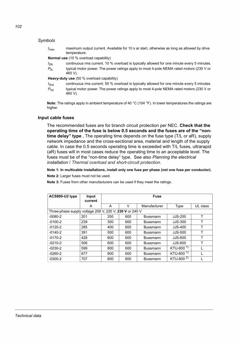
102
Symbols
Note: The ratings apply in ambient temperature of 40 °C (104 °F). In lower temperatures the ratings are higher.
Input cable fusesThe recommended fuses are for branch circuit protection per NEC. Check that the operating time of the fuse is below 0.5 seconds and the fuses are of the “non-time delay” type . The operating time depends on the fuse type (T/L or aR), supply network impedance and the cross-sectional area, material and length of the supply cable. In case the 0.5 seconds operating time is exceeded with T/L fuses, ultrarapid (aR) fuses will in most cases reduce the operating time to an acceptable level. The fuses must be of the “non-time delay” type. See also Planning the electrical installation / Thermal overload and short-circuit protection.Note 1: In multicable installations, install only one fuse per phase (not one fuse per conductor). Note 2: Larger fuses must not be used. Note 3: Fuses from other manufacturers can be used if they meet the ratings.
Imax maximum output current. Available for 10 s ar start, otherwise as long as allowed by drive temperature.
Normal use (10 % overload capability)I2N continuous rms current. 10 % overload is typically allowed for one minute every 5 minutes.PN typical motor power. The power ratings apply to most 4-pole NEMA rated motors (230 V or
460 V). Heavy-duty use (50 % overload capability)I2hd continuous rms current. 50 % overload is typically allowed for one minute every 5 minutes.Phd typical motor power. The power ratings apply to most 4-pole NEMA rated motors (230 V or
460 V).
ACS800-U2 type Input current
Fuse
A A V Manufacturer Type UL classThree-phase supply voltage 208 V, 220 V, 230 V or 240 V-0080-2 201 250 600 Bussmann JJS-250 T-0100-2 239 300 600 Bussmann JJS-300 T-0120-2 285 400 600 Bussmann JJS-400 T-0140-2 391 500 600 Bussmann JJS-500 T-0170-2 428 600 600 Bussmann JJS-600 T-0210-2 506 600 600 Bussmann JJS-600 T-0230-2 599 800 600 Bussmann KTU-800 1) L-0260-2 677 800 600 Bussmann KTU-800 1) L-0300-2 707 800 600 Bussmann KTU-800 2) L
Technical data

103
1) also 800 A class T fuse JJS-800 can be used for units without enclosure extension2) 900 A class L fuse KTU-900 must be used for units without eclocure extension
Ultrarapid (aR) fuses
Three-phase supply voltage 380 V, 400 V, 415 V, 440 V, 460 V, 480 V -0170-5 175 250 600 Bussmann JJS-250 T-0210-5 220 300 600 Bussmann JJS-300 T-0260-5 267 400 600 Bussmann JJS-400 T-0270-5 293 500 600 Bussmann JJS-500 T-0300-5 331 500 600 Bussmann JJS-500 T-0320-5 397 500 600 Bussmann JJS-500 T-0400-5 467 600 600 Bussmann JJS-600 T-0440-5 501 800 600 Bussmann KTU-800 1) L-0490-5 542 800 600 Bussmann KTU-800 1) L-0550-5 614 800 600 Bussmann KTU-800 2) L-0610-5 661 800 600 Bussmann KTU-800 2) L
PDM code: 00096931-G
ACS800-U2 size
Input current
A
FuseA A2s V Manufacturer Type
DIN 43653/110Size
Three-phase supply voltage 208 V, 220 V, 230 V or 240 V -0080-2 201 400 105 690 Bussmann 170M3169 1*-0100-2 239 500 145 690 Bussmann 170M5160 2-0120-2 285 550 190 690 Bussmann 170M5161 2-0140-2 391 800 465 690 Bussmann 170M6162 3-0170-2 428 800 465 690 Bussmann 170M6162 3-0210-2 506 1000 945 690 Bussmann 170M6164 3-0230-2 599 1250 1950 690 Bussmann 170M6166 3-0260-2 677 1600 3900 690 Bussmann 170M6169 3-0300-2 707 1600 3900 690 Bussmann 170M6169 3Three-phase supply voltage 380 V, 400 V, 415 V, 440 V, 460 V, 480 V -0170-5 175 400 105 000 690 Bussmann 170M3169 1*-0210-5 220 500 145 000 690 Bussmann 170M5160 2-0260-5 267 550 190 000 690 Bussmann 170M5161 2-0270-5 293 800 465 000 690 Bussmann 170M6162 3-0300-5 331 800 465 000 690 Bussmann 170M6162 3-0320-5 397 800 465 000 690 Bussmann 170M6162 3-0400-5 467 1000 945 000 690 Bussmann 170M6164 3-0440-5 501 1250 1 950 000 690 Bussmann 170M6166 3-0490-5 542 1250 1 950 000 690 Bussmann 170M6166 3-0550-5 614 1600 3 900 000 690 Bussmann 170M6169 3-0610-5 661 1600 3 900 000 690 Bussmann 170M6169 3
PDM code: 00096931-G
ACS800-U2 type Input current
Fuse
A A V Manufacturer Type UL class
Technical data

104
Cable typesCable sizing is based on NEC Table 310-16 for copper wires, 75 °C (167 °F) wire insulation at 40 °C (104 °F) ambient temperature. Not more than three current-carrying conductors in raceway or cable or earth (directly buried). For other conditions, dimension the cables according to local safety regulations, appropriate input voltage and the load current of the drive.
Cable EntriesInput, motor and brake resistor cable terminal sizes (per phase) and tightening torques are given below. For units without enclosure extension, one hole cable lugs (1/2 inch diameter) can be used. The maximum allowed width of the cable lug is 1.5 inches. For units with enclosure extension, two hole cable lugs (1/2 inch diameter) can be used.
Copper cables with concentric copper shieldMax. load
currentA
Cable type
AWG/kcmil57 675 488 3101 2114 1132 1/0154 2/0176 3/0202 4/0224 250 MCM or 2 x 1251 300 MCM or 2 x 1/0273 350 MCM or 2 x 2/0295 400 MCM or 2 x 2/0334 500 MCM or 2 x 3/0370 600 MCM or 2 x 4/0 or 3 x 1/0405 700 MCM or 2 x 4/0 or 3 x 2/0449 2 x 250 MCM or 3 x 2/0502 2 x 300 MCM or 3 x 3/0546 2 x 350 MCM or 3 x 4/0590 2 x 400 MCM or 3 x 4/0669 2 x 500 MCM or 3 x 250 MCM739 2 x 600 MCM or 3 x 300 MCM810 2 x 700 MCM or 3 x 350 MCM884 3 x 400 MCM or 4 x 250 MCM
1003 3 x 500 MCM or 4 x 300 MCM1109 3 x 600 MCM or 4 x 400 MCM1214 3 x 700 MCM or 4 x 500 MCM
Frame size
U1, V1, W1, U2, V2, W2, UDC+/R+, UDC-, R- Earthing PE Screw Tightening torque Screw Tightening torque
lbf ft lbf ftR7 1/2 37...55 5/16 11...16R8 1/2 37...55 5/16 11...16
Technical data

105
Dimensions and weights
H height without lifting lugs
W1 width of the basic unit
W2 width with the optional enclosure extension
W3 weight of the basic unit
W4 weight with the optional enclosure extension (basic configuration with switch fuse but without contactor and other options).
UL/CSA markingsThe ACS800-02 and the ACS800-U2 are C-UL US listed and CSA marked. The approvals are valid with rated voltages (up to 600 V).
ULThe drive is suitable for use on a circuit capable of delivering not more than 65 kA rms symmetrical amperes at the drive nominal voltage (600 V maximum for 690 V units).The drive provides overload protection in accordance with the National Electrical Code (US). See ACS800 Firmware Manual for setting. Default setting is off, must be activated at start-up.The drives are to be used in a heated indoor controlled environment. See section Ambient conditions for specific limits.Brake chopper - ABB has brake choppers that, when applied with appropriately sized brake resistors, will allow the drive to dissipate regenerative energy (normally associated with quickly decelerating a motor). Proper application of the brake chopper is defined in chapter Resistor braking. This can be applied to a single drive or multiple drives with DC bus connected to allow a sharing of regenerative energy.
Frame size UL type 1 W3 W4H1 W1 W2 Depthin. in. in. in. lb lb
R7 59.31 9.82 23.70 20.65 220 430R8 79.67 13.66 31.24 24.47 507 827
Technical data

106
Technical data

107
Dimensional drawings
The dimensions are given in milllimetres and [inches].
Dimensional drawings

108
Frame size R7
US
gla
nd
/con
duit
pla
te64
5797
46 H
Dimensional drawings

109
Frame size R8
3AFE
645
6416
1-D
US
gla
nd
/co
nd
uit
pla
te
Dimensional drawings

110
Frame size R7 with enclosure extension – bottom entry
6462
5942
1/2
- B
Dimensional drawings

111
6462
5942
2/2
- C
Dimensional drawings
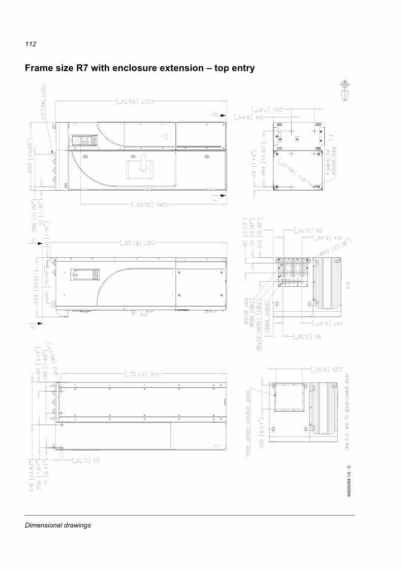
112
Frame size R7 with enclosure extension – top entry
6462
6264
1/2
- C
Dimensional drawings
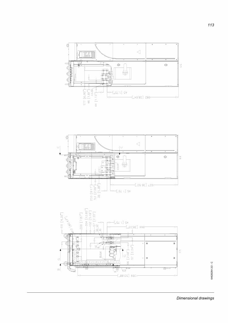
113
6462
6264
2/2
- C
Dimensional drawings
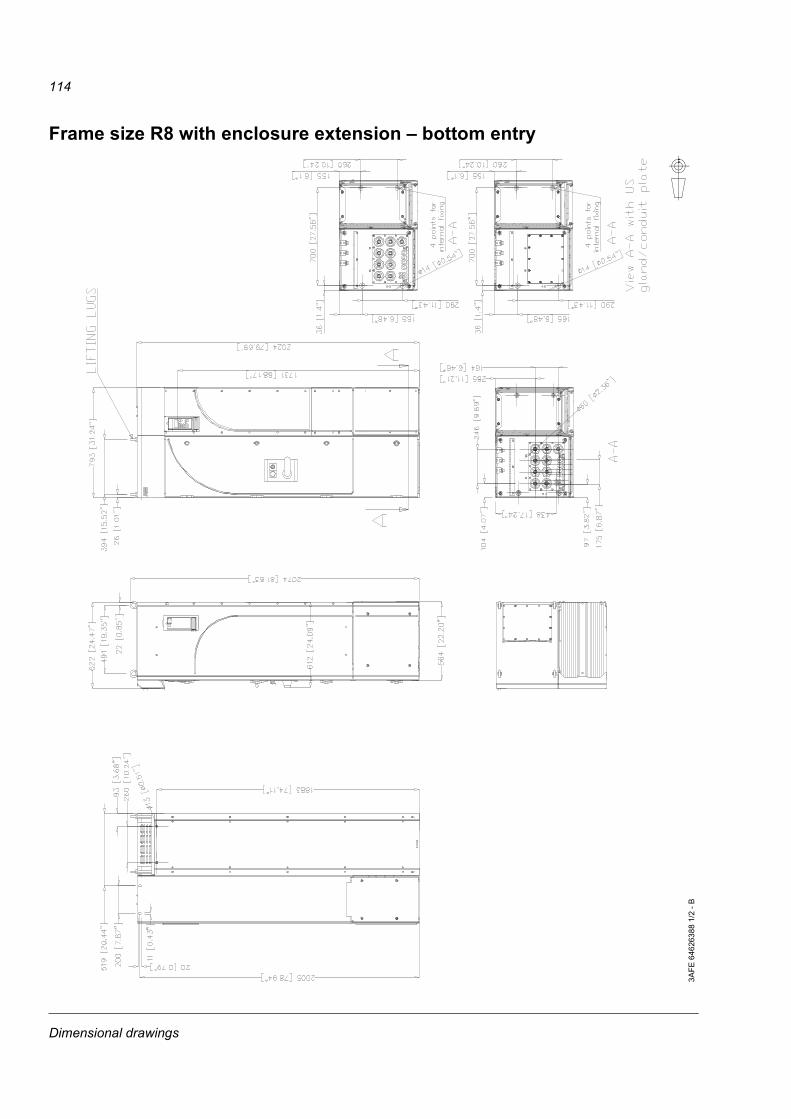
114
Frame size R8 with enclosure extension – bottom entry
3AFE
646
2638
8 1/
2 - B
Dimensional drawings

115
3AFE
646
2638
8 2/
2 - B
Dimensional drawings

116
Frame size R8 with enclosure extension – top entry
3AFE
646
2637
0 1/
2 - C
Dimensional drawings
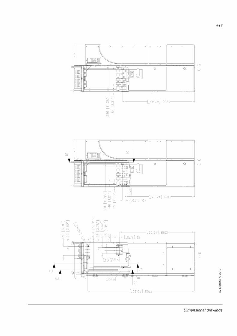
117
3AFE
646
2637
0 2/
2 -C
Dimensional drawings

118
Dimensional drawings

119
Resistor braking
What this chapter containsThis chapter describes how to select, protect and wire brake choppers and resistors. The chapter also contains the technical data.
To which products this chapter appliesThis chapter applies to the ACS800-01/U1 (frame sizes R2 to R6), the ACS800-02/U2 (frame sizes R7 and R8), the ACS800-04/U4 (frame sizes R7 and R8) and the ACS800-07/U7 (frame sizes R6, R7 and R8).
Availability of brake choppers and resistors for the ACS800Frame R2 and R3 drives have a built-in brake chopper as standard equipment. For frames R4 and up, brake choppers are optionally available as built-in units, indicated in the type code by +D150.
Resistors are available as add-on kits. For the ACS800-07/U7, resistors are available as factory installed.
How to select the correct drive/chopper/resistor combination1. Calculate the maximum power (Pmax) generated by the motor during braking.
2. Select a suitable drive / brake chopper / brake resistor combination for the application according to the following tables (take account of other factors in the drive selection also). The following condition must be met:
where
3. Check the resistor selection. The energy generated by the motor during a 400-second period must not exceed the resistor heat dissipation capacity ER.
If the ER value is not sufficient, it is possible to use a four-resistor assembly in which two standard resistors are connected in parallel, two in series. The ER value of the four-resistor assembly is four times the value specified for the standard resistor.
Pbr denotes Pbr5, Pbr10, Pbr30, Pbr60, or Pbrcont depending on the duty cycle.
Pbr > Pmax
Resistor braking

120
Note: A resistor other than the standard resistor can be used provided that:
• its resistance is not lower than the resistance of the standard resistor.
WARNING! Never use a brake resistor with a resistance below the value specified for the particular drive / brake chopper / resistor combination. The drive and the chopper are not able to handle the overcurrent caused by the low resistance.
• the resistance does not restrict the braking capacity needed, i.e.,
where
• the heat dissipation capacity (ER) is sufficient for the application (see step 3 above).
Optional brake chopper and resistor(s) for the ACS800-01/U1
Pmax maximum power generated by the motor during brakingUDC voltage over the resistor during braking, e.g.,
1.35 · 1.2 · 415 VDC (when supply voltage is 380 to 415 VAC),1.35 · 1.2 · 500 VDC. (when supply voltage is 440 to 500 VAC) or1.35 · 1.2 · 690 VDC (when supply voltage is 525 to 690 VAC).
R resistor resistance (ohm)
ACS 800-01 type Braking power of the chopper and the drive
Brake resistor(s)
Pbrcont(kW)
Type R(ohm)
ER(kJ)
PRcont(kW)
230 V units-0001-2 0.55 SACE08RE44 44 248 1-0002-2 0.8 SACE08RE44 44 248 1-0003-2 1.1 SACE08RE44 44 248 1-0004-2 1.5 SACE08RE44 44 248 1-0005-2 2.2 SACE15RE22 22 497 2-0006-2 3.0 SACE15RE22 22 497 2-0009-2 4.0 SACE15RE22 22 497 2-0011-2 5.5 SACE15RE13 13 497 2-0016-2 11 SAFUR90F575 8 1800 4.5-0020-2 17 SAFUR90F575 8 1800 4.5-0025-2 23 SAFUR80F500 6 2400 6-0030-2 28 SAFUR125F500 4 3600 9-0040-2 33 SAFUR125F500 4 3600 9-0050-2 45 2xSAFUR125F500 2 7200 18-0060-2 56 2xSAFUR125F500 2 7200 18-0070-2 68 2xSAFUR125F500 2 7200 18
Pmax <UDC
R
2
Resistor braking
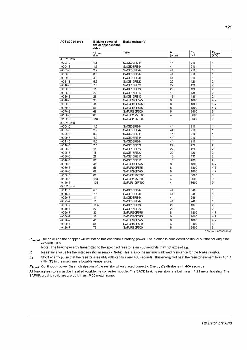
121
Pbrcont The drive and the chopper will withstand this continuous braking power. The braking is considered continuous if the braking time exceeds 30 s. Note: The braking energy transmitted to the specified resistor(s) in 400 seconds may not exceed ER.
R Resistance value for the listed resistor assembly. Note: This is also the minimum allowed resistance for the brake resistor. ER Short energy pulse that the resistor assembly withstands every 400 seconds. This energy will heat the resistor element from 40 °C
(104 °F) to the maximum allowable temperature.PRcont Continuous power (heat) dissipation of the resistor when placed correctly. Energy ER dissipates in 400 seconds. All braking resistors must be installed outside the converter module. The SACE braking resistors are built in an IP 21 metal housing. The SAFUR braking resistors are built in an IP 00 metal frame.
400 V units-0003-3 1.1 SACE08RE44 44 210 1-0004-3 1.5 SACE08RE44 44 210 1-0005-3 2.2 SACE08RE44 44 210 1-0006-3 3.0 SACE08RE44 44 210 1-0009-3 4.0 SACE08RE44 44 210 1-0011-3 5.5 SACE15RE22 22 420 2-0016-3 7.5 SACE15RE22 22 420 2-0020-3 11 SACE15RE22 22 420 2-0025-3 23 SACE15RE13 13 435 2-0030-3 28 SACE15RE13 13 435 2-0040-3 33 SAFUR90F575 8 1800 4.5-0050-3 45 SAFUR90F575 8 1800 4.5-0060-3 56 SAFUR90F575 8 1800 4.5-0070-3 68 SAFUR80F500 6 2400 6-0100-3 83 SAFUR125F500 4 3600 9-0120-3 113 SAFUR125F500 4 3600 9500 V units-0004-5 1.5 SACE08RE44 44 210 1-0005-5 2.2 SACE08RE44 44 210 1-0006-5 3.0 SACE08RE44 44 210 1-0009-5 4.0 SACE08RE44 44 210 1-0011-5 5.5 SACE08RE44 44 210 1-0016-5 7.5 SACE15RE22 22 420 2-0020-5 11 SACE15RE22 22 420 2-0025-5 15 SACE15RE22 22 420 2-0030-5 28 SACE15RE13 13 435 2-0040-5 33 SACE15RE13 13 435 2-0050-5 45 SAFUR90F575 8 1800 4.5-0060-5 56 SAFUR90F575 8 1800 4.5-0070-5 68 SAFUR90F575 8 1800 4.5-0100-5 83 SAFUR125F500 4 3600 9-0120-5 113 SAFUR125F500 4 3600 9-0140-5 135 SAFUR125F500 4 3600 9690 V units-0011-7 5.5 SACE08RE44 44 248 1-0016-7 7.5 SACE08RE44 44 248 1-0020-7 11 SACE08RE44 44 248 1-0025-7 15 SACE08RE44 44. 248 1-0030-7 18.5 SACE15RE22 22 497 2-0040-7 22 SACE15RE22 22 497 2-0050-7 30 SAFUR90F575 8 1800 4.5-0060-7 37 SAFUR90F575 8 1800 4.5-0070-7 45 SAFUR90F575 8 1800 4.5-0100-7 55 SAFUR80F500 6 2400 6-0120-7 75 SAFUR80F500 6 2400 6
PDM code 00096931-G
ACS 800-01 type Braking power of the chopper and the drive
Brake resistor(s)
Pbrcont(kW)
Type R(ohm)
ER(kJ)
PRcont(kW)
Resistor braking

122
Optional brake chopper and resistor(s) for the ACS800-02/U2, the ACS800-04/U4 and the ACS800-07/U7 ACS 800 type Frame
sizeBraking power of the chopper and the drive
Brake resistor(s)
5/60 sPbr5(kW)
10/60 sPbr10(kW)
30/60 sPbr30(kW)
Pbrcont(kW)
Type R(ohm)
ER(kJ)
PRcont(kW)
230 V units
-0080-2 R7 68 68 68 54 SAFUR 160F380 1.78 3600 9-0100-2 R7 83 83 83 54 SAFUR 160F380 1.78 3600 9-0120-2 R7 105 67 60 40 2xSAFUR200F500 1.35 10800 27-0140-2 R8 135 135 135 84 2xSAFUR160F380 0.89 7200 18-0170-2 R8 135 135 135 84 2xSAFUR160F380 0.89 7200 18-0210-2 R8 165 165 165 98 2xSAFUR160F380 0.89 7200 18-0230-2 R8 165 165 165 113 2xSAFUR160F380 0.89 7200 18-0260-2 R8 223 170 125 64 4xSAFUR160F380 0.45 14400 36-0300-2 R8 223 170 125 64 4xSAFUR160F380 0.45 14400 36400 V units
-0070-3 R6 - - - 68 SAFUR80F500 6 2400 6-0100-3 R6 - - - 83 SAFUR125F500 4 3600 9-0120-3 R6 - - - 113 SAFUR125F500 4 3600 9-0140-3 R7 135 135 100 80 SAFUR200F500 2.70 5400 13.5-0170-3 R7 165 150 100 80 SAFUR200F500 2.70 5400 13.5-0210-3 R7 165 150 100 80 SAFUR200F500 2.70 5400 13.5-0260-3 R8 240 240 240 173 2XSAFUR210F575 1.70 8400 21-0320-3 R8 300 300 300 143 2xSAFUR200F500 1.35 10800 27-0400-3 R8 375 375 273 130 4xSAFUR125F500 1.00 14400 36-0440-3 R8 473 355 237 120 4xSAFUR210F575 0.85 16800 42-0490-3 R8 500 355 237 120 4xSAFUR210F575 0.85 16800 42500 V units
-0100-5 R6 - - - 83 SAFUR125F500 4 3600 9-0120-5 R6 - - - 113 SAFUR125F500 4 3600 9-0140-5 R6 - - - 135 SAFUR125F500 4 3600 9-0170-5 R7 165 132 2) 120 80 SAFUR200F500 2.70 5400 13.5-0210-5 R7 198 132 2) 120 80 SAFUR200F500 2.70 5400 13.5-0260-5 R7 198 1) 132 2) 120 80 SAFUR200F500 2.70 5400 13.5-0270-5* R8 240 240 240 240 2xSAFUR125F500 2.00 7200 18-0300-5* R8 280 280 280 280 2xSAFUR125F500 2.00 7200 18-0320-5 R8 300 300 300 300 2xSAFUR125F500 2.00 7200 18-0400-5 R8 375 375 375 234 2XSAFUR210F575 1.70 8400 21-0440-5 R8 473 473 450 195 2xSAFUR200F500 1.35 10800 27-0490-5 R8 480 480 470 210 2xSAFUR200F500 1.35 10800 27-0550-5 R8 600 400 4) 300 170 4xSAFUR125F500 1.00 14400 36-0610-5 R8 600 3) 400 4) 300 170 4xSAFUR125F500 1.00 14400 36690 V units
-0070-7 R6 - - - 45 SAFUR90F575 8.00 1800 4.5-0100-7 R6 - - - 55 SAFUR80F500 6.00 2400 6-0120-7 R6 - - - 75 SAFUR80F500 6.00 2400 6-0140-7 R7 125 5) 110 90 75 SAFUR80F500 6.00 2400 6-0170-7 R7 125 6) 110 90 75 SAFUR80F500 6.00 2400 6-0210-7 R7 125 6) 110 90 75 SAFUR80F500 6.00 2400 6-0260-7 R7 135 7) 120 100 80 SAFUR80F500 6.00 2400 6-0320-7 R8 300 300 300 260 SAFUR200F500 2.70 5400 13.5-0400-7 R8 375 375 375 375 SAFUR200F500 2.70 5400 13.5-0440-7 R8 430 430 430 385 SAFUR200F500 2.70 5400 13.5-0490-7 R8 550 400 315 225 2xSAFUR125F500 2.00 7200 18-0550-7 R8 550 400 315 225 2xSAFUR125F500 2.00 7200 18-0610-7 R8 550 400 315 225 2xSAFUR125F500 2.00 7200 18
PDM code 00096931-G
Resistor braking

123
Pbr5 Maximum braking power of the drive with the specified resistor(s). The drive and the chopper will withstand this braking power for 5 seconds per minute.
Pbr10 The drive and the chopper will withstand this braking power for 10 seconds per minute.Pbr30 The drive and the chopper will withstand this braking power for 30 seconds per minute.Pbrcont The drive and the chopper will withstand this continuous braking power. The braking is considered continuous if the braking time
exceeds 30 s.Note: Check that the braking energy transmitted to the specified resistor(s) in 400 seconds does not exceed ER.
R Resistance value for the resistor assembly. Note: This is also the minimum allowed resistance for the brake resistor.ER Short energy pulse that the resistor assembly withstands every 400 seconds. This energy will heat the resistor element from
40 °C (104 °F) to the maximum allowable temperature.PRcont Continuous power (heat) dissipation of the resistor when placed correctly. Energy ER dissipates in 400 seconds.
* ACS800-Ux types only1) 240 kW possible if ambient temperature is below 33 °C (91 °F)2) 160 kW possible if ambient temperature is below 33 °C (91 °F)3) 630 kW possible if ambient temperature is below 33 °C (91 °F)4) 450 kW possible if ambient temperature is below 33 °C (91 °F)5) 135 kW possible if ambient temperature is below 33 °C (91 °F)6) 148 kW possible if ambient temperature is below 33 °C (91 °F)7) 160 kW possible if ambient temperature is below 33 °C (91 °F)
Resistor braking

124
All braking resistors must be installed outside the converter module. The resistors are built in an IP 00 metal frame. The 2xSAFUR and 4xSAFUR resistors are connected in parallel.
Resistor installation and wiringAll resistors must be installed outside the drive module in a place where they will cool.
WARNING! The materials near the brake resistor must be non-flammable. The surface temperature of the resistor is high. Air flowing from the resistor is of hundreds of degrees Celsius. Protect the resistor against contact.
Use the cable type used for drive input cabling (refer to chapter Technical Data) to ensure the input fuses will also protect the resistor cable. Alternatively, two-conductor shielded cable with the same cross-sectional area can be used. The maximum length of the resistor cable(s) is 10 m (33 ft). For the connections, see the power connection diagram of the drive.
Combined braking cycles for R7:
• After Pbr5, Pbr10 or Pbr30 braking, the drive and the chopper will withstand Pbrcont continuously.• Pbr5, Pbr10 or Pbr30 braking is allowed once every minute.• After Pbrcont braking, there has to be at least 30 seconds without any braking if the subsequent braking power is greater than Pbrcont.• After Pbr5 or Pbr10 braking, the drive and the chopper will withstand Pbr30 within a total braking time of 30 seconds.• Pbr10 braking is not acceptable after Pbr5 braking.Combined braking cycles for R8:
• After Pbr5, Pbr10 or Pbr30 braking, the drive and the chopper will withstand Pbrcont continuously. (Pbrcont is the only allowed braking power after Pbr5, Pbr10 or Pbr30.)
• Pbr5, Pbr10 or Pbr30 braking is allowed once every minute.• After Pbrcont braking, there has to be at least 60 seconds without any braking if the subsequent braking power is greater than Pbrcont.
Pbr
t
Pbr5 or Pbr10
Pbr30
Pbrcont
min. 30 s max 30 s min. 30 s
No braking
Examples
min. 30 s
max 5 s or 10 s
max 30 s
Pbr
t
Pbr5, Pbr10 or Pbr30
Pbrcont
min. 60 s
No braking
Examples
min. 60 s
max 5 s, 10 s or 30 s
Resistor braking

125
ACS800-07/U7If ordered, the resistors are factory installed in a cubicle(s) next to the drive cabinet.
Protection of frame sizes R2 to R5 (ACS800-01/U1)It is highly recommended to equip the drive with a main contactor for safety reasons. Wire the contactor so that it opens in case the resistor overheats. This is essential for safety since the drive will not otherwise be able to interrupt the main supply if the chopper remains conductive in a fault situation.
Below is a simple example wiring diagram.
Protection of frame size R6 (ACS800-01, ACS800-07) and frame sizes R7 and R8 (ACS800-02, ACS800-04, ACS800-07)
A main contactor is not required for protecting against resistor overheating when the resistor is dimensioned according to the instructions and the internal brake chopper is in use. The drive will disable power flow through the input bridge if the chopper remains conductive in a fault situation. Note: If an external brake chopper (outside the drive module) is used, a main contactor is always required.
A thermal switch (standard in ABB resistors) is required for safety reasons. The cable must be shielded and not longer than the resistor cable.
ACS800
U1 V1 W1
L1 L2 L3
1
2
3
4
5
6
13
14
3
4
1
2
K1
�
FusesOFF
ON
Thermal switch (standard in ABB resistors)
Resistor braking

126
With Standard Application Program, wire the thermal switch as shown below. By default, the drive will stop by coasting when the switch opens.
For other application programs, the thermal switch may be wired to a different digital input. Programming of the input to trip the drive by “EXTERNAL FAULT” may be needed. See the appropriate firmware manual.
Brake circuit commissioningFor Standard Application Program:
• Enable the brake chopper function (parameter 27.01).
• Switch off the overvoltage control of the drive (parameter 20.05).
• Check the resistance value setting (parameter 27.03).
• Frame sizes R6, R7 and R8: Check the setting of parameter 21.09. If stop by coasting is required, select OFF2 STOP.
For the use of the brake resistor overload protection (parameters 27.02...27.05), consult an ABB representative.
WARNING! If the drive is equipped with a brake chopper but the chopper is not enabled by parameter setting, the brake resistor must be disconnected because the protection against resistor overheating is then not in use.
For settings of other application programs, see the appropriate firmware manual.
1 DI12 DI23 DI34 DI45 DI56 DI67 +24VD8 +24VD9 DGND110 DGND211 DIIL
�
Thermal switch (standard in ABB resistors)
RMIO:X22 or X2: X22
Resistor braking


3AFE
645
6737
3 R
ev C
EN
EFFE
CTI
VE: 1
8.11
.200
3
ABB OyAC DrivesP.O. Box 184FIN-00381 HELSINKIFINLANDTelephone +358 10 22 11Fax +358 10 22 22681Internet http://www.abb.com
ABB Inc.Automation TechnologiesDrives and Motors16250 West Glendale DriveNew Berlin, WI 53151USATelephone 262 785-3200
800-HELP-365Fax 262 780-5135