Embed Size (px)
Citation preview

Version 2002 © European Aluminium Association ([email protected]) 1
Manufacturing – Cutting Table of contents 2 Cutting ..................................................................................................................................... 2
2.1 What to find in this section ............................................................................................... 2 2.2 Machining ......................................................................................................................... 3
2.2.1 Introduction ............................................................................................................... 3
2.2.2 Machining methods ................................................................................................... 5
2.2.3 Machinability ........................................................................................................... 15
2.2.4 Tools ....................................................................................................................... 16
2.2.5 Lubrication .............................................................................................................. 23
2.2.6 Machine requirements ............................................................................................ 25 2.3 Shear cutting .................................................................................................................. 26
2.3.1 Definitions ............................................................................................................... 26
2.3.2 Cut Edge Quality ..................................................................................................... 27
2.3.3 Blanking .................................................................................................................. 28
2.3.4 Trimming ................................................................................................................. 29
2.3.5 Piercing ................................................................................................................... 34

Version 2002 © European Aluminium Association ([email protected]) 2
2 Cutting
2.1 What to find in this section
Shearing with wide or narrow gap influences the edge quality and the generation of slivers and galling
From a component manufacturer's viewpoint the field of "cutting" (or "separating") comprises essentially
the chipless shear separation of sheet and extrusion as well as
the machining of bulk parts like castings and forgings. The understanding of the mechanisms involved in both technology fields has progressed significantly in recent years to allow highest productivity and machine times in the fabrication of aluminium components. To exploit fully the productivity potential of aluminium requires, however, the exact tuning of
working parameters, tooling, machinery and lubrication
to the specific requirements of the component's material. These aspects are treated in the following chapters: Machining of aluminium parts and components
Machining methods Machinability (planned for 2nd edition) Tools Lubrication Machine requirements (planned for 2nd edition)
Shear cutting of sheet, stampings and extrusions
Blanking Trimming Piercing
(More information will be added in forthcoming editions of the Manual)
Version 2002 © European Aluminium Association ([email protected]) 3
2.2 Machining
2.2.1 Introduction
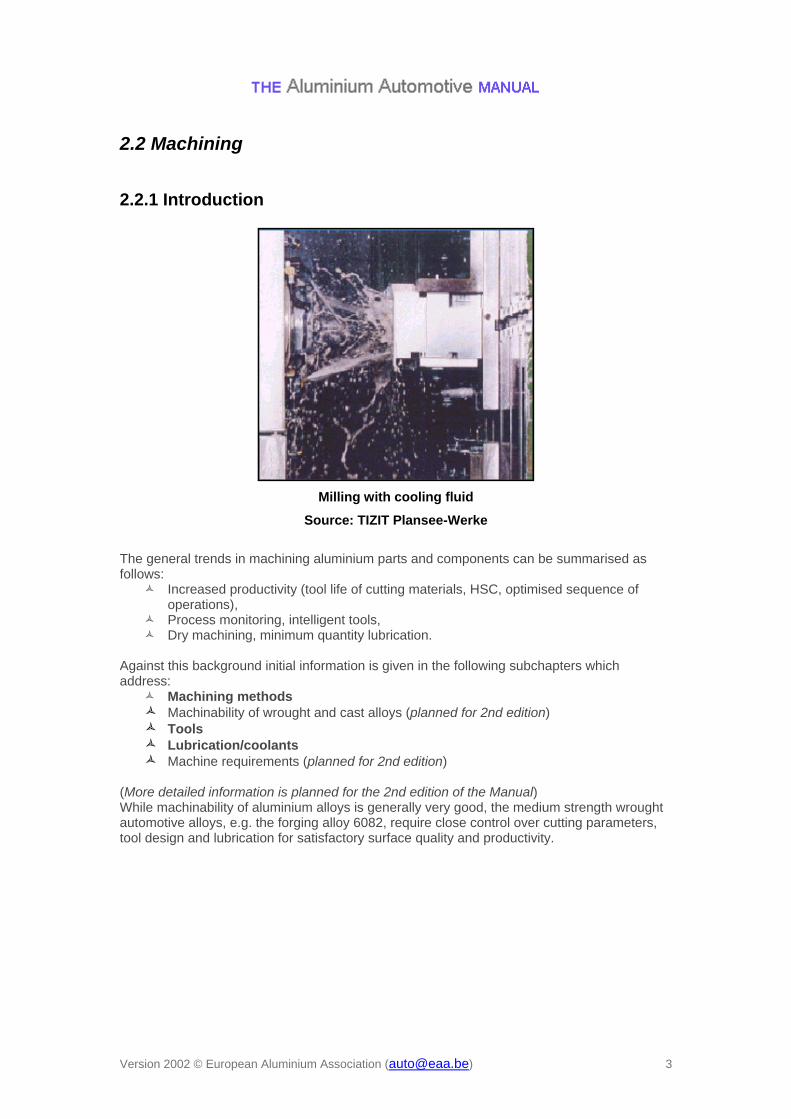
Milling with cooling fluid
Source: TIZIT Plansee-Werke
The general trends in machining aluminium parts and components can be summarised as follows:
Increased productivity (tool life of cutting materials, HSC, optimised sequence of operations),
Process monitoring, intelligent tools, Dry machining, minimum quantity lubrication.
Against this background initial information is given in the following subchapters which address:
Machining methods
Machinability of wrought and cast alloys (planned for 2nd edition) Tools Lubrication/coolants Machine requirements (planned for 2nd edition)
(More detailed information is planned for the 2nd edition of the Manual) While machinability of aluminium alloys is generally very good, the medium strength wrought automotive alloys, e.g. the forging alloy 6082, require close control over cutting parameters, tool design and lubrication for satisfactory surface quality and productivity.

Version 2002 © European Aluminium Association ([email protected]) 4
Machinability rating of aluminium alloys according to TIZIT/Planseewerke
Version 2002 © European Aluminium Association ([email protected]) 5
2.2.2 Machining methods
Overview
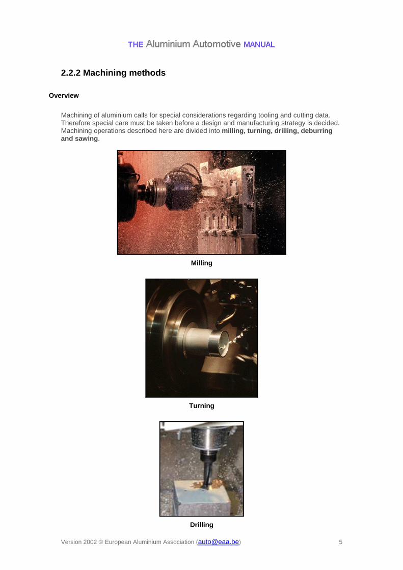
Machining of aluminium calls for special considerations regarding tooling and cutting data. Therefore special care must be taken before a design and manufacturing strategy is decided. Machining operations described here are divided into milling, turning, drilling, deburring and sawing.
Milling
Turning
Drilling

Version 2002 © European Aluminium Association ([email protected]) 6
Deburring
Sawing
Generally speaking cutting speed is much higher for aluminium than for steels, etc.
Version 2002 © European Aluminium Association ([email protected]) 7
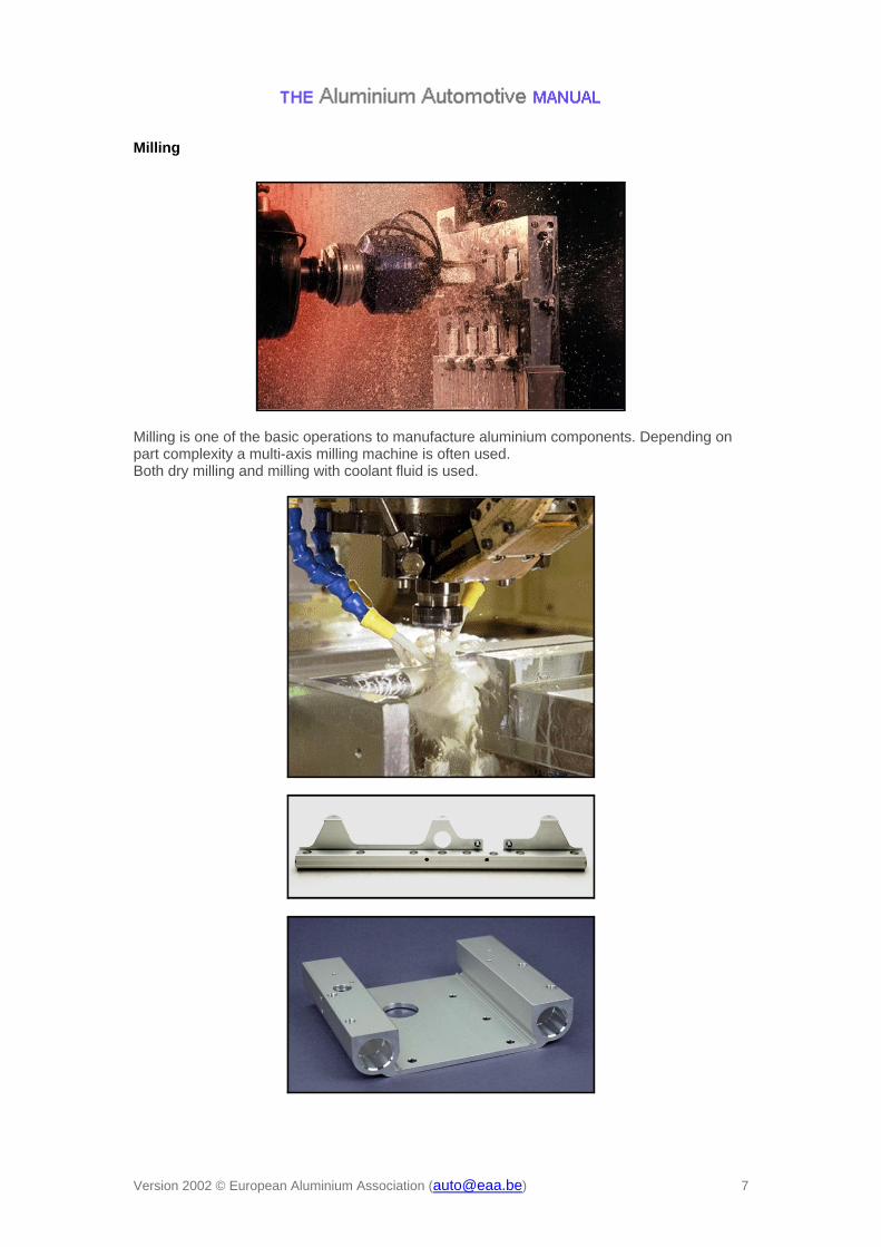
Milling
Milling is one of the basic operations to manufacture aluminium components. Depending on part complexity a multi-axis milling machine is often used. Both dry milling and milling with coolant fluid is used.

Version 2002 © European Aluminium Association ([email protected]) 8
High speed milling
General The definition of high speed milling varies. Generally speaking it means that cutting speed is increased dramatically compared with "normal" machining. For aluminium cutting speeds above approx. 2500 m/min are considered as HSM. The idea is that temperature in the workpiece is kept down as 80% of the heat goes into the chip. Cutting speed Cutting speed is defined as multiplying the circumference of the tool (or work piece when
turning) with the rotational speed. This means that to reach 2500 m/min with a 20 mm
milling tool the rpm must be approx. 40.000, but for a 50 mm tool it is enough with approx. 16.000 rpm. Feed rate The feed rate is normally kept at 0.03 – 0.2 mm/cutting edge. Advantages
Due to small cutting forces thin sections can be produced Productivity gain is 40-60% over traditional milling
Disadvantages
Special cutter holder necessary due to high centrifugal forces. HSK better than ISO.
Cutters have to be well balanced, higher demands as the rpm increases.

Version 2002 © European Aluminium Association ([email protected]) 9
Turning
Work in progress for 2nd edition.

Version 2002 © European Aluminium Association ([email protected]) 10
Drilling
Drilling is one of the basic operations, either to create a finished hole or to open up a work piece for plunge roughing etc. Drilling usually requires emulsion blends of 10-12%. The drills are made of solid carbide or high speed steel with various coatings to reduce friction and adhesion.
Twist drill Cutting speed 200-300 m/min
Feed rate < 1500 mm/min
Step drill Used to create two diameters in one operation.
The two diameters complicate choice of cutting data.

Version 2002 © European Aluminium Association ([email protected]) 11
Tube drill Cutting speed 120-150 m/min Feed rate 100-140 mm/min.
Pressurised emulsion important for chip removal. Lengths <100xD
Long twist drill... ...right through Water channels through entire drill give longer drill life and better cutting data.
Cutting speed 200-300 m/min, feed rate <1500 mm/min. Lengths <25xD

Version 2002 © European Aluminium Association ([email protected]) 12
Deburring
Manual deburring with deburring tool, file, knife etc. Only suitable when other methods cannot be used or at low production volumes.
Brush deburring Brushes (normally Nylon covered with Al2O3 or stainless steel), either in a fixed equipment or a hand operated machine.

Version 2002 © European Aluminium Association ([email protected]) 13
Tumbling Workpieces are placed in a large cylinder either alone or together with ceramic chips. A compound (water emulsion) is used to flush away contaminations.

Version 2002 © European Aluminium Association ([email protected]) 14
Sawing
Aluminium extrusions are cut to specified lengths using specially designed cutter blades. If several cutter blades with different diameters are used beside each other, different shaping operations can be performed at the same time when the end is cut (instead of separate milling operations). Typical cutting speeds are 4000 – 6000 m/min. For often used cutter dimensions the following rpm is used:
600 = 1700 - 2000 rpm
850 = 1500 - 1900 rpm

Version 2002 © European Aluminium Association ([email protected]) 15
2.2.3 Machinability Literature:
Johne, P., Handbuch der Aluminiumzerspanung, Düsseldorf: Aluminium-Verlag, 1984
Work in progress

Version 2002 © European Aluminium Association ([email protected]) 16
2.2.4 Tools
Cutter types
Solid Carbide Used for drills and small diameter mills (D< 20 mm)
High Speed Steel Used at lower cutting speeds. This type of tool can tolerate vibration without damage, as it is not brittle. Can be refurbished numerous times.
Version 2002 © European Aluminium Association ([email protected]) 17
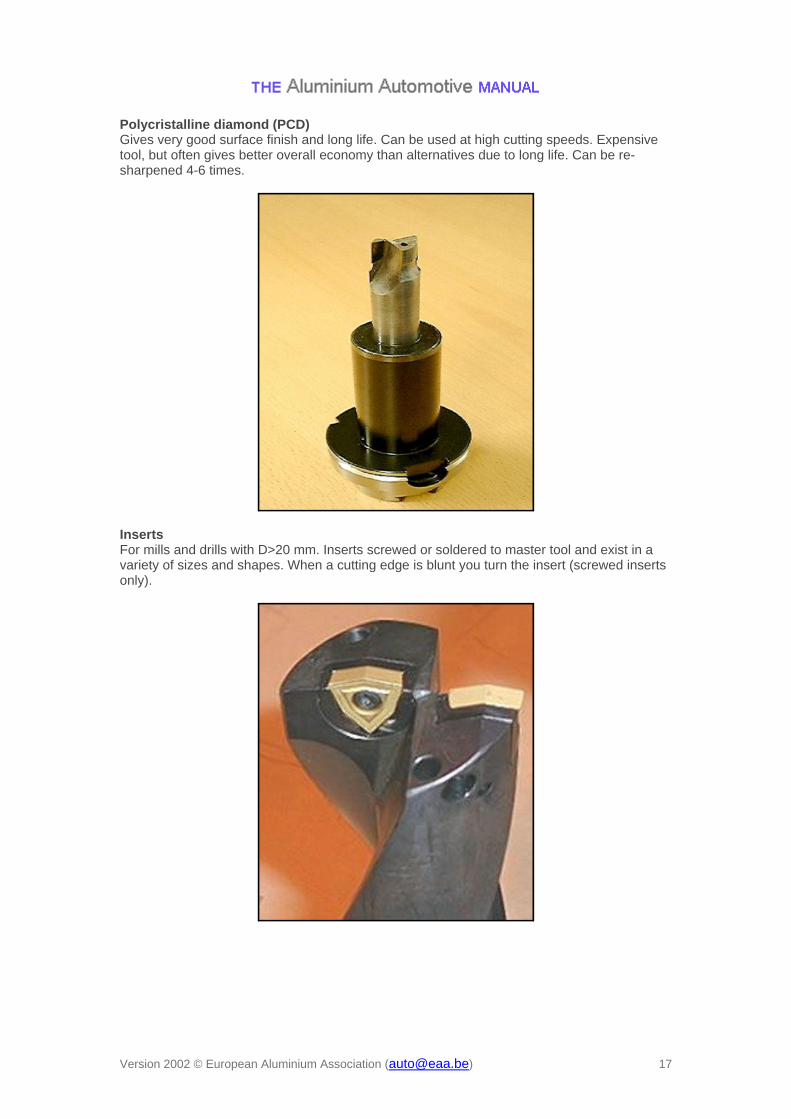
Polycristalline diamond (PCD) Gives very good surface finish and long life. Can be used at high cutting speeds. Expensive tool, but often gives better overall economy than alternatives due to long life. Can be re-sharpened 4-6 times.
Inserts For mills and drills with D>20 mm. Inserts screwed or soldered to master tool and exist in a variety of sizes and shapes. When a cutting edge is blunt you turn the insert (screwed inserts only).

Version 2002 © European Aluminium Association ([email protected]) 18
Cutter holders
Cutter holders exist in a number of different versions. Depending on requirements for stability, torque, space etc a holder suitable for each application can be chosen. Hydraulic holder (+) torque 181 Nm on 20 mm pin (+) inserts cover D2 – D20 mm
(–) loosening of clamping force and torque over time
Hydromechanic holder (+) torque 579 Nm on 20 mm pin (+) inserts cover D2 – D20 mm (+) small radial movement (0,002 mm)
(–) large diameter Used when you need high accuracy, stability and torque.
Version 2002 © European Aluminium Association ([email protected]) 19
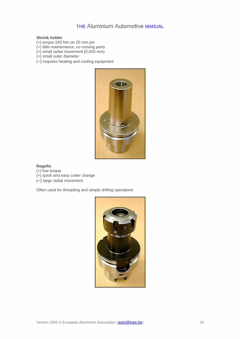
Shrink holder (+) torque 243 Nm on 20 mm pin (+) little maintenance, no moving parts (+) small radial movement (0,003 mm) (+) small outer diameter
(–) requires heating and cooling equipment
Regofix (+) low torque (+) quick and easy cutter change
(–) large radial movement
Often used for threading and simple drilling operations

Version 2002 © European Aluminium Association ([email protected]) 20
Fixtures
All machining operations subject the work piece to large forces. Therefore, it must be clamped rigidly during the operation. When designing a part for machining suitable clamping surfaces must be provided.
Clamping can be done mechanically or with vacuum, magnet or hydraulic devices.

Version 2002 © European Aluminium Association ([email protected]) 21
Hydraulic fixture
A hydraulic fixture can be used for non-flat work pieces as it adapts to the shape of the work piece.
The sketch and picture below show the principle behind the hydraulic fixture. Hydraulic pressure presses the pistons towards the work piece with uniform force.
Version 2002 © European Aluminium Association ([email protected]) 22
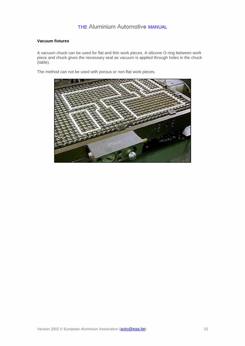
Vacuum fixtures
A vacuum chuck can be used for flat and thin work pieces. A silicone O-ring between work piece and chuck gives the necessary seal as vacuum is applied through holes in the chuck (table). The method can not be used with porous or non-flat work pieces.
Version 2002 © European Aluminium Association ([email protected]) 23
2.2.5 Lubrication
Introduction
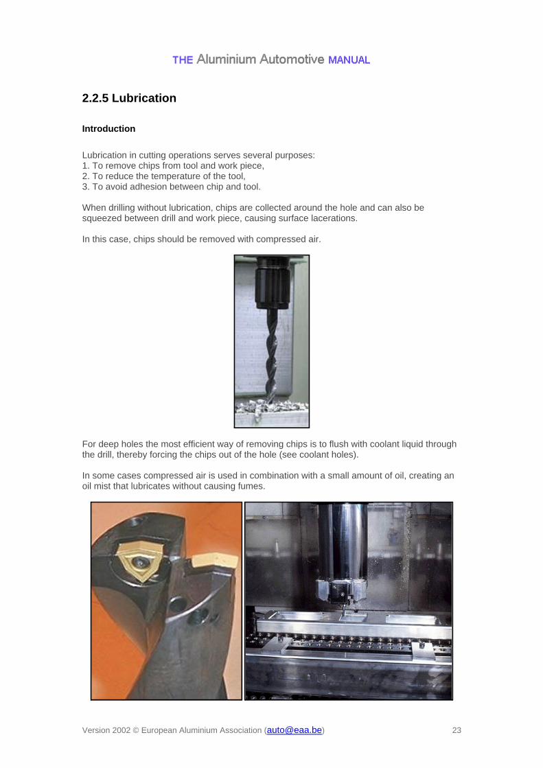
Lubrication in cutting operations serves several purposes: 1. To remove chips from tool and work piece, 2. To reduce the temperature of the tool, 3. To avoid adhesion between chip and tool. When drilling without lubrication, chips are collected around the hole and can also be squeezed between drill and work piece, causing surface lacerations. In this case, chips should be removed with compressed air.
For deep holes the most efficient way of removing chips is to flush with coolant liquid through the drill, thereby forcing the chips out of the hole (see coolant holes). In some cases compressed air is used in combination with a small amount of oil, creating an oil mist that lubricates without causing fumes.

Version 2002 © European Aluminium Association ([email protected]) 24
Milling without lubrication
In many cases milling and turning without liquid lubrication is a better alternative. The reasons for this are:
Lubrication liquid causes fumes when heated by the tool, New cutter inserts are often designed to work dry, No problem with thermal shock of the cutter inserts from liquid.
There is also another alternative, where "minimal" lubrication is used. In this case the cutter is flushed with air containing a very small amount of oil. This gives better lubrication than dry cutting without causing problems with oil fumes. HSM is always done without lubrication, as the heat generated in the cutting operation is removed with the chip.

Version 2002 © European Aluminium Association ([email protected]) 25
2.2.6 Machine requirements
Work in progress

Version 2002 © European Aluminium Association ([email protected]) 26
2.3 Shear cutting
2.3.1 Definitions Literature:
Tool and Manufacturing Engineers Handbook, Vol. 2 : Forming, Society of Manufacturing Engineers, 1984
Metals Handbook, Vol. 14, ASM International, 1988. The most common method of shear cutting aluminium sheet in high volume is to use a punch and die set mounted in a single acting press. Punch-and-die tools used for aluminium are very similar to those used for steel. The main difference is the clearance required between the punch and die blades. Blanking: separation of required blank shape from incoming sheet or coil stock. Trimming: cutting of excess material from the periphery of a drawn or formed part. Piercing: punching of holes.
Punch-and-die cutting process of sheet metal (schematics)

Version 2002 © European Aluminium Association ([email protected]) 27
2.3.2 Cut Edge Quality Blanked or sheared edge aspect varies over the sheet thickness. It is described by four regions:
rollover burnish fracture
burr Small rollover radius, small burr height and burnish depth less than one quarter of the gauge are required for sheet metal forming of autobody applications. Cut edge aspect depends on alloy mechanical properties and thickness, and on tooling characteristics (clearance, blade radius, cutting angle, blade material…) Cut edge aspect affects formability of the free edge:
forming of stretch flanges hem flanging between inner and outer autobody panels
Cut edge surface aspect and characteristics
Version 2002 © European Aluminium Association ([email protected]) 28
2.3.3 Blanking See also:
AAM – Materials – 5 Wrought materials production > Automotive sheet > From ingot to strip and panel > Cutting of panels
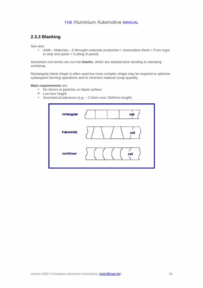
Aluminium coil stocks are cut into blanks, which are stacked prior sending to stamping workshop. Rectangular blank shape is often used but more complex shape may be required to optimize subsequent forming operations and to minimize material scrap quantity. Main requirements are:
No slivers or particles on blank surface
Low burr height Geometrical tolerance (e.g.: ~2-3mm over 1500mm length)

Version 2002 © European Aluminium Association ([email protected]) 29
2.3.4 Trimming
Trimming quality
Literature:
Tool and Manufacturing Engineers Handbook, Vol. 2 : Forming, Society of Manufacturing Engineers, 1984
Daniel D. , Shahani R., Baldo R., Hoffmann JL., Development of 6xxx Alloy Aluminum Sheet for Autobody Outer Panels: Bake Hardening, Formability and Trimming Performance, IBEC 1999 - SAE CD-Rom proceedings (Paper N° 1999-01-3195)
Li M. and Fata G.: Sliver reduction in trimming aluminum autobody sheet, Proceedings of SAE congress 1999, SAE Paper 1999-01-0661
Trimming quality depends on:
punch/die clearance cutting angle penetration depth rake tool materials
sharpness of cutting edge Good cut edge quality must be obtained to avoid slivers or fine particles generation in the tools. The slivers can carry through the downstream processes and cause damage to the surface of formed parts which results in high repair rate for outer panels. Also particles accumulation can generate galling problems. Good cut edge quality may be required to maintain formability of the free edge for subsequent forming operations.
R&D trimming tool

Version 2002 © European Aluminium Association ([email protected]) 30
Sliver generation
Literature:
Li M. and Fata G.: Sliver reduction in trimming aluminum autobody sheet, Proceedings of SAE congress 1999, SAE Paper 1999-01-0661
Daniel D. , Shahani R., Baldo R., Hoffmann JL., Development of 6xxx Alloy Aluminum Sheet for Autobody Outer Panels: Bake Hardening, Formability and Trimming Performance, IBEC 1999 - SAE CD-Rom proceedings (Paper N° 1999-01-3195)
Sliver generation is associated with galling, induced by excessive blade friction on the cut surface in the fracture region. In high volume production of aluminium outer autobody panels, slivers generated by the trimming can accumulate in the stamping tools, resulting in surface defects requiring costly manual rework. The robustness of the trimming process and, consequently, the productivity of the stamping lines of high volume aluminium outer autobody panels is improved by specific metallurgical development for outer panel applications. Guidelines for trimming tool parameters are established to minimize sliver generation.
Left: Optical micrograph of the cut surface of 1mm 6016 sheet
Right: Particles and sliver collected on self-adhesive tape
Good quality cut surface

Version 2002 © European Aluminium Association ([email protected]) 31
Guidelines – Effect of clearance
Literature:
Daniel D., Shahani R., Baldo R. and Hoffmann J.L.: Development of 6xxx Alloy Aluminum Sheet for Autobody Outer Panels: Bake Hardening, Formability and Trimming Performance, Proceedings of IBEC 1999, Paper 1999-01-3195
Li M. and Fata G.: Sliver reduction in trimming aluminum autobody sheet, Proceedings of SAE congress 1999, SAE Paper 1999-01-0661
Schematic of punch-and-die cutting process
Punch/Die Clearance
~ 8-10% of the gauge for low strength alloys (UTS up to 230MPa) ~10-14% of the gauge for high strength alloys (UTS over 230MPa) These values apply for blanking. Smaller clearance is used if subsequent forming operation requires free edge formability. Tool wear is increased when small clearance is used.

Version 2002 © European Aluminium Association ([email protected]) 32
Example : Cut edge aspect of AA6016-T4 (1mm) trimmed with a 0° cutting angle and different punch/die clearances.
Effect of clearance

Version 2002 © European Aluminium Association ([email protected]) 33
Guidelines – Tool design
Literature:
Li M. and Fata G.: Sliver reduction in trimming aluminum autobody sheet, Proceedings of SAE congress 1999, SAE Paper 1999-01-0661
Daniel D. , Shahani R., Baldo R., Hoffmann JL., Development of 6xxx Alloy Aluminum Sheet for Autobody Outer Panels: Bake Hardening, Formability and Trimming Performance, IBEC 1999 - SAE CD-Rom proceedings (Paper N° 1999-01-3195)
Cutting angle Good cut edge quality, with no burr and sliver/particle generation, can be obtained by trimming at an oblique angle (up to 40°) with a large range of clearance (2-20% of sheet thickness). Contrary to steel, zero cutting angle, i.e. normal trimming should be avoided. Rake or "guillotine" effect Rake, used to reduce cutting load, should be kept small to avoid part distortion and to limit penetration depth which could increase slivers/particles generation. Punch penetration or cutting edge entry For recommended clearance, penetration depth of 50% of gauge thickness is enough for fracture to occur. In practice, higher penetration should be used to ensure total shearing of the part but it may increase slivers/particles generation. Cutting tool material and surface treatment High-grade steels (hardness below 58HRC) are used for high volume production. Surface treatments used for aluminium cold forming are recommended. Sharpness of cutting edges Tool wear increases burr height.
Version 2002 © European Aluminium Association ([email protected]) 34
2.3.5 Piercing
Punching of holes
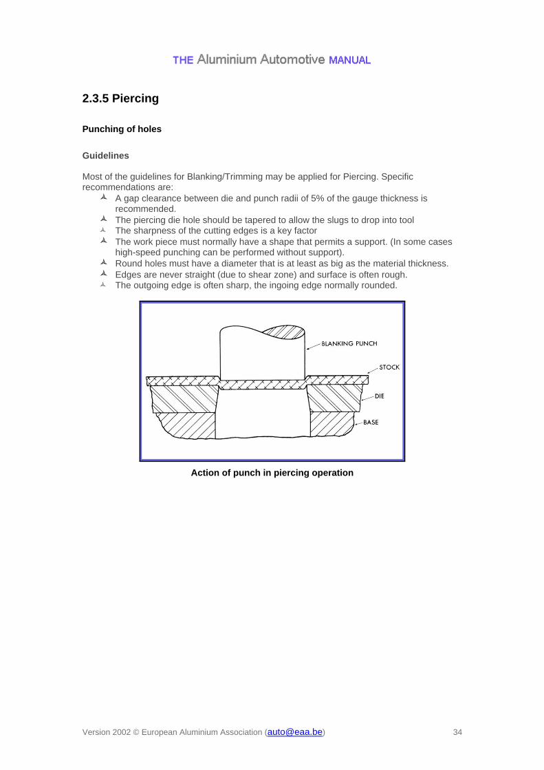
Guidelines Most of the guidelines for Blanking/Trimming may be applied for Piercing. Specific recommendations are:
A gap clearance between die and punch radii of 5% of the gauge thickness is recommended.
The piercing die hole should be tapered to allow the slugs to drop into tool The sharpness of the cutting edges is a key factor
The work piece must normally have a shape that permits a support. (In some cases high-speed punching can be performed without support).
Round holes must have a diameter that is at least as big as the material thickness. Edges are never straight (due to shear zone) and surface is often rough. The outgoing edge is often sharp, the ingoing edge normally rounded.
Action of punch in piercing operation

Version 2002 © European Aluminium Association ([email protected]) 35
Examples – Punching holes into extrusions
Punching is normally the fastest and most economical way to create a hole or to trim material along an edge. Although it calls for special tooling this is compensated by fast operation in a relatively cheap machine. Punching is therefore a particularly useful method to extend the form spectrum of extruded shapes.
Source: G. Olsson, SAPA
Seat tracks
Source: G. Olsson, SAPA
Source: G. Olsson, SAPA