Embed Size (px)
Citation preview

International Journal of Production Research,Vol. 43, No. 11, 1 June 2005, 2195–2216
Optimal process planning for a combined punch-and-laser cutting
machine using ant colony optimization
G. G. WANG*y and S. Q. XIEz
yDepartment of Mechanical and Manufacturing Engineering, University of Manitoba,
Winnipeg, MB, Canada R3T 5V6
zDepartment of Mechanical Engineering, University of Auckland, Private Bag 92019,
Auckland, New Zealand
(Received January 2005)
A machine that performs both punching and laser-cutting operations is referredas combined punch-and-laser machine. Such a machine has been in the market forabout two decades. Although process-planning tools have been used on such acombined machine, the optimization of process planning dedicated to combinedmachines, based on our literature search results, has never been directly studied.This work addresses the process-planning problem for the combined punch-and-laser machine by integrating knowledge, quantitative analysis, and numericaloptimization approaches. The proposed methodology helps making decisions onfollowing issues: (i) which type of operation should be applied to each feature,and (ii) what is the optimal operation sequence (tool path) to achieve the max-imum manufacturing efficiency. The ant colony optimization (ACO) algorithmsare employed in searching the optimal tool path. Sensitivities of controlparameters of ACO are also analysed. Through applications, the proposedmethod can significantly improve the operation efficiency for the combinedpunch-and-laser machine. The method can also be easily automated andintegrated with the nesting and G-code generation processes. Some issues andpossible future research topics have also been discussed.
Keywords: Combination machine; Combined punch-and-laser machine; Sheetmetal; Process planning; Optimization; Ant colony optimization
1. Introduction
Modern computer numeric controlled (CNC) turret punches represent highly versa-tile machine tools capable of producing sheet metal and plastic components quicklyand accurately. However, the versatility of such turret punches is limited in thatmaterial can be removed from the work piece only by a punching type operation.When large areas of the work piece are to be removed, or when the work piece is to besubdivided into a number of separable work pieces, or when relatively long or largediameter parts are to be made, this can be accomplished only by a series of slightlyoverlapping punching type metal removal operations. Such overlapping material
*Corresponding author. Email: [email protected]
International Journal of Production Research
ISSN 0020–7543 print/ISSN 1366–588X online # 2005 Taylor & Francis Group Ltd
http://www.tandf.co.uk/journals
DOI: 10.1080/00207540500070376

removal operations can be effectively used to increase the versatility of a punch,
however, those operations, at times, lead to undesired consequences, such as forma-
tion of burred edges, inability to produce highly accurate, smooth side edges, relative
slowness of operation, etc. (Clark and Carbone 1980). Moreover, when the cut-out
shape is not one of the common punch tool shapes, special tools have to be
made and the costs of making such tools are normally high. As a result, many
cutting or shearing type operations are performed by other machine tools in a
subsequent operation that requires additional work piece handling. This multi-
machinery requirement influences not only the manufacturing efficiency, but also
the manufacturing quality and cost. The above stated reasons motivated the devel-
opment of a so-called combined punch-and-laser cutting machine (Clark and
Carbone 1980), or compound machine (Katayama 1989a, b, Xie et al. 2001), or
combination punch press and laser cutting machine (Klingel and Doettling
1990, Ulrish 2000). In this work, this machine will be referred as combined
punch-and-laser machine.
The combined punch-and-laser machine was first invented in 1980 (Clark and
Carbone 1980), and then gradually matured by overcoming its vibration interference
problem through a number of patents (Bredow 1982, Katayama 1989a, b, Klingel
and Doettling 1990, Ulrish 2000). With variations on detailed machine structure as
described in various patents, a combined punch-and-laser machine, in principle,
integrates a punch tool with a laser beam cutter into one machine. The current
version of the machine allows the separation of the punching system from the
laser system, and a standard punch tool can be readily retrofitted with a laser
system to therefore become a combined machine (Ulrish 2000).
The advantages of the combined punch-and-laser machine are manifold. Such a
machine increases the ability of conventional punching equipment to provide large
and/or irregularly shaped parts in the work piece. It represents a major advance in
the art of machine tools to provide a single machine tool capable of high speed, high
accuracy punching, cutting, and surface marking wherein all functions are control-
lable from a central automatic control and wherein work piece movement is accom-
plished by a single mechanism so as to eliminate the necessity of work piece handling
between operations.
In the past 20 years, the industry embraced the combined punch-and-laser
machine. Companies that supply such machines include, for example, Dalsin
Industries, Inc. in Minnesota, LVD Corporation in North Carolina, GE Capital
Manufacturing in Connecticut, all USA, TRUMPF Group, Germany, Amada
America, Inc. in California, USA, and Finn-Power International, Inc. Figure 1
shows an example of such a machine by Amada America.
Given the capability of combined punch-and-laser machines, the process plan-
ning of the machine becomes more complex. However, no study has been found in
literature directly on process planning for combined punch-and-laser machines.
Neither was found the optimization of process planning dedicated to combined
punch-and-laser machines. This is incommensurate with the development of the
machine in industry. Two related studies are found on the process planning for a
flexible manufacturing cell that includes a punch and a laser (Ghosh et al. 1993), and
a simulation method to optimize the work sequence in a job shop (Endo et al. 1996).
While, process planning as a topic in general has a long history with many fruitful
results. A recent work with a good review is done by Li et al. (2004).
2196 G. G. Wang and S. Q. Xie

This work will focus on the process-planning problem for the combinedpunch-and-laser machine in order to improve the efficiency of the machine andfully automate the process from layout nesting to machining. This work will bethe first on optimal process planning for combined punch-and-laser machines.
2. Process planning problem for a combined punch-and-laser machine
For the process planning of a combined punch-and-laser machine, one has to maketwo important decisions for each batch of work pieces, i.e.
. Which feature is to be punched or cut?
. What is the optimal sequence of operation to ensure the overall maximummachine efficiency?
Let us use the work piece shown in figure 2 as an example. On a sheet metal of1000� 1120mm, two types of components are laid out. The first component has asquare shape with round corners, a central hole, and four small holes. The secondcomponent is a combination of a semicircle and a rectangle, with a small hole. Forthe combined machine, there are four different operation features, i.e. 23 small holesof F50, four large holes of F180, four contours for the first component, and 7contours for the second component. For automatic process planning, which featureis to be punched and which is to be cut? If the first question were answered, whatwould be the optimal operation sequence that yields the maximum machineefficiency?
This work will develop a quantitative method guided by heuristics to address thefirst question, and then apply the ACO algorithms to answer the second question.The methods are then tested with the problem shown in figure 2 and a more complexsheet metal work piece. Integration of the proposed methods with Computer-AidedNesting (CAN) and G-Code generation tools will also be discussed.
Before discussing the proposed methodology, some assumptions are given first toconfine us to an appropriate scope of study:
. Operation sequence (process) will be optimized to improve the machineefficiency of the combined punch-and-laser machine. The increase of machine
Figure 1. Amada Apelio combined punch-and-laser machine (Amada American, Inc. �).
2197Optimal process planning for a combined punch-and-laser cutting

efficiency is expected to translate into reduced machine cost, labour cost andincreased throughput, etc.
. Given the fact that most combined machines have only one punch headand one laser cutter, this study will focus on this type of machine.Extension of the proposed method to machines with multiple heads shouldnot be difficult.
. Combined punch-and-laser machine is assumed to be CNC so that theoptimal operation sequence can be output to generate G-codes.
3. Proposed strategy
In today’s sheet metal manufacturing industry, all of the components to be fabri-cated are first laid out on the sheet metal in a computer. This process is calledComputer-Aided Nesting (CAN). For CAN, the input data is usually a standardDXF format file. CAN recognizes and stores all the geometric information ofthe components to be laid out. It then generates a scheme, usually optimal, tolayout the components on the sheet metal to achieve a certain objective, which isusually the maximum material utilization ratio. Certain CAN tools can even auto-matically generate G-Codes for CNC devices such as punch press, cutters, etc. (Xieet al. 2004). In this step, the operation (including both punching and cutting)sequence has to be determined before outputting the G-Codes. For a combinedpunch-and-laser machine, the type of operation should be determined for eachfeature, as compared with conventional machines normally involving only onetype of operation.
Φ50x23
1120
1000
x
y
0
Φ180x4
Figure 2. Batch of work pieces to be machined in the combined punch-and-laser machine(unit:mm).
2198 G. G. Wang and S. Q. Xie

Each component may contain more than one operation feature. For example, thefirst component shown in figure 2 consists of the outer contour, the large centre holeand four small corner holes. In total, there are three different operation features inthis component. Similarly, the second component in figure 2 consists of two differentoperation features, which are the outer contour and the circle. The two differentcomponents yet share an identical operation feature, i.e. the small holes of F50.Therefore for the sheet metal manufacturing, we concern about the operationfeatures rather than components. For the example in figure 2, in total four differentoperation features exist.
Since CAN stores all the necessary geometric information of the components tobe laid out, it is not difficult to find the geometric information of each operationfeatures. The process-planning task therefore involves the operation and operationsequence on each operation feature. From the information stored in CAN process,operation features are first classified and coded according to its geometric shape andsize. Holes of different sizes are treated as different features.
3.1 Decision I: Punch or cut?
The punch operation is usually limited by the available punch tools and the capacityof the punch press, though it can potentially reach a very high efficiency. The max-imum feature size for punching should be within the limit of the machine such as themaximum power and force limit. The minimum hole diameter in punching shouldnormally be larger than the sheet thickness. Also there should be an available punchtool for such a feature (Schey 2000, Kalpakjian and Schimid 2003). For the laserbeam cutting, the allowable minimum size of a feature is, in general, 0.5mm for CO2
type of lasers; and 0.08mm for Nd:YAG lasers (Schey 2000). The first task forprocess planners for a combined punch-and-laser machine is to check if there isany operation feature out of the capacity of both the punch and the laser cutter.If the answer is yes, other means rather than the combined punch-and-laser machineare to be used.
Assuming all the features can be fabricated by either punching, laser cutting orboth, decisions on using punch or laser cutting can be made using the followingprocedure:
Step 0: Identify each operation feature from the existing geometric data, asdiscussed above.
Step 1: According to the limitation of punch-and-laser cutting operations, classifyall of the operation features to punch (cannot be laser cut), laser cutting(cannot be punched), and an intermediate group. It is easy to understandthat the difficulty comes from the features that fall into the intermediategroup. The goal is eventually to determine whether either punch or lasercutting is to be used for each feature in this group. Such a decision on whichoperation is to be used for the intermediate group mainly concerns with thetime of operation (which can be translated into costs).
Step 2: Decide an operation for each operation feature in the intermediate group.
As we know that the punch operation generally has a very high efficiency and it isinexpensive for high volume production as compared with the laser cutting. Based onthis intuitive understanding, it is reasonable to deduct the following rules in supportof Decision I.
2199Optimal process planning for a combined punch-and-laser cutting

. Rule I: The operation feature with the largest quantity is assigned forpunching. This rule ensures that at least there is one feature to be punchedfully to take advantage of the punch operation.
. Rule II: For the rest of the features in the intermediate group, unless theminimum time for (laser) cutting the feature including the tool exchange timeis less than the minimum punch time if punch continues to be used, thefeature is to be punched.
Assume Tc is the total laser cutting time if the laser is used, and Tp is the total punchtime if the punch is used. Therefore,
Tc ¼ tc þ tt ¼Lc
Vc
þLt
Vt
ð1Þ
where tc is the actual laser cutting time, which equals the cutting length Lc dividedby the laser cutting speed Vc; tt is the travelling time between identical operationfeatures, or the positioning time, which equals the total length of travelling Lt, andthe positioning speed Vt. Similarly for the punch operation, we have
Tp ¼ tp þ tt ¼ n � tstroke þLt
Vt
ð2Þ
where n is the quantity of the operation feature and tstroke is the time per punchstroke. Assuming tx is the tool exchange time between the punch-and-laser cutter,Rule II can be written as:
. Rule II: If min(Tc)<min(Tp)þ tx, the feature is to be fabricated by lasercutting; otherwise, it is to be punched.
As the punch speed, position speed, and tool exchange time of a single machinenormally does not vary with the operation, the criterion can be further simplified:
minðTcÞ ¼Lc
maxðVcÞþminðLtÞ
Vt
< minðTpÞ þ tx ¼ n �minðtstrokeÞ þminðLtÞ
Vt
þ tx
Lc
maxðVcÞ< n �minðtstrokeÞ þ tx ð3Þ
where max(Vc) is the maximum allowable laser cutting speed for a certain operationfeature, which might vary with the material, sheet thickness, environment, etc. So isit for min(tstroke). It is also noted that as the punch speed can reach very high inmodern machines, tstroke is thus very small. For example, the Trumatic 6000L–1300combined punch-and-laser machine made by Trumpf, Inc. has a maximum punchrate as 900 strokes/min (Trumpf 2004), which translates to 15 strokes/s. For a smallquantity of features, i.e. n is small, the term n � tstroke becomes negligible.
Applying Rule II, one can make decisions on all the other features in the inter-mediate group. Eventually all of the operation features can be classified to either thepunch or the cut group.
3.2 Decision II: What is the optimal operation sequence?
Now that the operation is decided for each feature, the next question is what isthe best operation sequence that gives the maximum manufacturing efficiency.
2200 G. G. Wang and S. Q. Xie

To address the question, following issues are to be considered:
. What is the optimal sequence to fabricate features from the two groups? Is itmore efficient to perform the punch operations all at once than a mixedpunch-and-laser operation, or vice versa?
. For different features in one operation group, what is the reasonablesequence of operation? In other words, what is the manufacturing orderfor different features with the same operation?
. Based on the answers to the first two questions, what is the best sequenceof manufacturing? In other words, what is the shortest travelling path tofabricate all the features?
As the tool exchange is still a time consuming process, intuitively it is more advanta-geous to perform one type of operation all at once. There exists a possibility that byoptimizing the tool travelling path the time saved in the travelling may counteractthe increase of tool shuffling. In this work, we assume that the tool exchange time ismore of a concern and stipulate that all of the punch operations will be performedfirst, followed by the laser cutting operations. For the second question, we need todistinguish the punch group from the cut group. For features in the punch group,one can easily find that inner features are to be manufactured first. For example, if aring is to be manufactured, the central hole is to be punched first and then the outercircle from the sheet metal. For the cut group, similar rules apply. If there is no innerfeature in the group and since we assume there is only one laser cutter and there is noneed to change tools, all of the features in the cut group can then be treated as onlyone feature. Their machining sequence will be determined by the optimal tool path.In this work, the ACO algorithms are employed and tailored to search for theoptimal travelling path among copies of each feature and the optimal transitionbetween different types of features. Details of the optimization will be described inthe following section.
In summary, figure 3 illustrates the proposed process planning process for thecombined punch-and-laser machine.
4. Ant colony optimization algorithms
The development of Ant Colony Optimization (ACO) algorithms was inspired by theobservation that a colony of ants has great potential to carry out a coordinatedactivity. Their main medium of communication is through the building up of thepath through an artificial chemical substance called ‘pheromone’. When ants leavenests to search for food, they lay a trail of pheromone on their path. The number ofants that has travelled on the same path determines the strength of the pheromonetrail. The ant that travels the shortest path reinforces the path with more amount ofpheromone. After a certain period of time, the ants, as a group, find the shortesttravelling path. ACO algorithms were first developed by Dorigo et al. (1996). ThenACO algorithms have been modified and applied to solve many problems such as thequadratic assignment problem, travelling salesman problem (TSP), vehicle routingproblem, connection-oriented network routing, graph colouring, sequencing, sche-duling, optical network problem, etc. Interested readers can find most of the relevantreferences on ACO algorithms through the website developed by Dorigo (2003). TheACO algorithms are chosen in this work based on the following reasons: (1) they
2201Optimal process planning for a combined punch-and-laser cutting

have been successfully applied to the Travelling Salesman Problem (TSP), whichshares many similarities between the tool path problem for the combined machine;(2) by applying the ACO algorithms to solve production problems we can gain betterunderstanding of this emerging technique; and (3) we may test the efficacy of thealgorithms and provide guidelines on the use of this technique in process planning.Choosing ACO, however, does not exclude the possible application of other meta-heuristics such as genetic algorithms (Gen and Cheng 1997), simulated annealing(Kirkpatrick et al. 1983), particle swarm optimization (Eberhart and Kennedy 1995),tabu search (Glover and Laguna 1996), etc. to this problem.
This work gives a brief overview of the essence of the ACO algorithms by usingthe travelling salesman (TSP) problem (Dorigo et al. 1996).
Given L cities, the TSP is the problem of finding a minimal length closed tourthat visits each city once. Let bi(t) (i¼ 1, . . . ,L) be the number of ants in city i at timet and let
m ¼XLi¼1
biðtÞ ð4Þ
be the total number of ants. Each ant has the following characteristics:
. When going from city i to city j, it lays a substance, called trail, on edge (i, j).
. It chooses a city to go to with a probability pij(t) that is a function of the citydistance and of the amount of trail present on the connecting edge.
. Movement to already visited cities in one tour is prohibited.
The key of the ant algorithms is to define the scheme of updating the trail, and designthe pij(t) function. Different choices about when and how to update the trails, as wellas the pij(t) function, causes different instantiation of the ACO algorithms. This work
Ident ify operation features from CAN geometric data
Classify features to punch - only, cut - only, and intermediate groups based on the capacity of the punch and laser cutter.
Move the first feature of the largest quantity from the intermediate group to the punch- only group
Apply Rule II for rest features in the intermediate group to complete the classification
Generate G - Codes and perform all the punch operation, followed by the cutting
Optimise the tool path for all the features using the ACO algorithms
Figure 3. Flow chart of the process planning procedure for the combined punch-and-lasermachine.
2202 G. G. Wang and S. Q. Xie

introduces the Ant-quantity and Ant-cycle algorithms developed by Dorigo et al.(1996).
Let �ijðtÞ be the intensity of trail on edge (i, j) at time t. At each iteration of thealgorithm, trail intensity becomes
�ijðtþ 1Þ ¼ � � �ijðtÞ þ��ijðt,tþ 1Þ ð5Þ
where � is a value in (0, 1) and (1��) is the evaporation rate of trail, and
��ijðt,tþ 1Þ ¼Xmk¼1
��kijðt,tþ 1Þ ð6Þ
where ��kijðt, tþ 1Þ is the quantity per unit of length of trail substance (pheromone inreal ants) laid on edge (i, j) by the k-th ant between time t and tþ 1.
For the Ant-quantity algorithm,
��kijðt, tþ 1Þ ¼
Q
dijif k-th ant goes from i to j between t and tþ 1
0 Otherwise
8<: ð7Þ
where dij is the distance from city i to city j; Q is a user defined constant. If dij isreplaced with Lk, which is the tour length of the k-th ant, then the Ant-quantityalgorithm becomes the Ant-cycle algorithm. The Ant-cycle algorithm takes the entiretour length as a feedback to update the trait, while the Ant-quantity takes the localdistance as the feedback. It was found in general more efficient than the Ant-quantityalgorithm for the closed-loop TSP (Dorigo et al. 1996).
The transition probability pij(t) function from city i to city j for the k-th ant isdefined as:
pijðtÞ ¼
½�ijðtÞ��½�ij �
�
Pj 2 allowed ½�ijðtÞ�
�½�ij�
�if j 2 allowed
0 otherwise
8<: ð8Þ
where �ij is called visibility and it equals the inverse of the distance dij from town i totown j; � and � are parameters that allow users to contrast the relative importance oftrail versus visibility. Following the recommendation in Dorigo et al. (1996), thiswork chooses � ¼ 1, � ¼ 2, � ¼ 0:5, and Q ¼ 100:
For the standard TSP, normally the number of ants, m, is set to be L, thenumber of cities. The problem is initialized so that there is one and only one antat each city.
5. Application of ACO algorithms in operation sequence planning
For the proposed operation sequence planning for the combined punch-and-lasermachine, there are two slightly different types of optimization problems. As theoperations are performed in a sequence and the material flow on a workstationhas a certain direction, the optimization problem is not a standard closed-loopTSO problem. For batches on a combined punch-and-laser machine, the startingpoint of each batch should usually be given. Assuming there are two consecutivebatches of work, the machine has to start from the starting point of the first batch,and then moves to the starting point of the second batch once the first is finished.
2203Optimal process planning for a combined punch-and-laser cutting

Between the two starting points, the tool can either return to the starting point(origin) after completing each feature, or continue from its current location forthe next feature. Specifically, two types of optimization problems exist correspondingto two situations.
. For the first feature, the tool should start from a fixed location and end at apoint that yields the shortest travelling path for copies of the first feature.For the second and following features, it starts from the current tool locationand ends at a point that yields the shortest travelling path for copies of eachfeature.
. For the last feature, the tool should start from the current location and end atthe starting point of the next work batch.
This work applies the algorithms described in Dorigo et al. (1996) with minormodifications corresponding to the above mentioned two types of problems:
. For both types of problems, the TSP is changed from a closed loop to anopen loop problem. Both Ant-quantity and Ant-cycle algorithms wereemployed. They both have similar performance. It is found that theAnt-quantity algorithm often gives better solutions than the Ant-cyclealgorithm, while the latter converges more quickly to the neighbourhoodof the global optimum. This phenomenon is due to the presence of a strongconstraint, i.e. the path has to start from a given point. Secondly, theAnt-quantity algorithm does not include the entire tour length as the feed-back; it thus has more chances to generate random information to reach theglobal optimum. On the other hand, since the Ant-cycle algorithm uses theentire tour length as a ‘global’ feedback, it guides the search quickly to benear the global optimum but the feedback may be too strong to prevent morerandom steps to reach the final solution.
. For the first type of problem, all the ants are initialized to be at one location,i.e. the starting point of a particular path. Hence, all identified optimal pathshave to start from the given location.
. For the second type of problem, besides that all the ants are initialized to beat one location, the path distance includes the distance between the finalfeature to the starting point of the next batch. The overall distance is thenused as the tour length for the Ant-cycle algorithm.
The next section will present detailed information on how the proposed method wasapplied to solve the problem illustrated in figure 2 and a more complex problem.The solutions are compared with those generated by conventional experience-basedprocess planning.
5.1 Example 1
As discussed above, the problem described in figure 2 entails four different operationfeatures. Applying the rule ‘The operation feature with the largest quantity isassigned for punching’, one can easily decide the small holes are to be punched asshown in figure 4. For the two types of contours shown in figure 5, we assume thatthere is no such big punch tool available and they have to be cut.
For the large holes in figure 6, we need to call equation (3) to calculate thetime for each alternative. Let us assume that the maximum laser cutting speed is
2204 G. G. Wang and S. Q. Xie

10m/min, the tool exchange time is 3s, and the maximum punch stroke is 900/min.Applying equation (3),
Lc
maxðVcÞ¼
180 � 3:14159 � 4 � 60
10 � 103¼ 13:6s
n �minðtstrokeÞ þ tx ¼ 4 � 1 � 60=900þ 3 ¼ 3:3s
;Lc
maxðVcÞ> n �minðtstrokeÞ þ t
Thus, the four large holes are to be punched.
Figure 4. Punch-for-sure feature.
Figure 5. Contour features of Example 1.
2205Optimal process planning for a combined punch-and-laser cutting

5.1.1 Tool path optimization. The coordinate system is set up as shown in figure 2.The starting point (100, 100) is the centre of the small circle at the left bottom cornerof the sheet.
Small holes. To apply the ACO algorithm searching for the optimal path, eachhole-centre is considered as a city in a typical TSP set-up. The task is to findthe minimum distance to travel through all the cities starting from a given city.The optimal path is found by running the ant algorithm and plotted as the solidline in figure 7. The dotted line indicates an intuitive path that a reasonable engineerwould generate. For clarity, the dotted line is drawn away from the circle centres; itin fact should goes through the circle centres. From figure 7, it is clear that bothpaths end at (1100, 100).
Large holes. The following feature to be machined is the large hole, which is also apunch operation (recall the rule to finish all the punching first, followed by lasercutting). Please note that the starting point is the end of the last path, i.e. the circlecentre at the upper right corner shown in figure 7. It is at (830, 830). The optimal andintuitive paths are drawn in figure 8. The intuitive path was generated on theassumption that the tool has to return to the origin from its current locationbefore operating on the second feature.
Contours. Since there is no other inner feature, the contours shown in figure 5 arecut together. The laser is assumed to start from the left bottom corner of eachfeature, traverse along the contour, and return to the left bottom corner. For thepath comparison purpose, the actual traverse length along lead-in line, lead-out line,and the perimeter of each feature is identical regardless of what the operation processis. Therefore, only the bottom left corner is used to represent each feature in figure 5.
Figure 6. Large holes, punch or cut?
2206 G. G. Wang and S. Q. Xie

Starting from the end of the last path (190, 560), the path is expected to end at thestarting point of the next batch of work, which is assumed to be (1100, 100) forExample 1. The optimal and the intuitive paths are plotted in figure 9.
Table 1 summarizes the details of the optimal as compared with intuitive processplanning results. The total reduced travelling distance in a 1000� 1120mm sheetfrom 11 942 to 10 046 is 1896mm.
x
y
0 Intuitive pathOptimal path
Figure 7. Comparison of the optimal and intuitive paths for small holes in Example 1.
Intuitive pathOptimal pathx
y
0
Figure 8. Comparison of the optimal and intuitive paths for large holes in Example 1.
2207Optimal process planning for a combined punch-and-laser cutting

5.2 Example 2
Example 2 shows a more complicated batch of work pieces (see figure 10). It includesfour different types of components, i.e. the rectangular block with holes, ring, smallhead clip, and large head clip. On the operation feature level, there are 104 smallholes of a diameter F50, 31 holes of F60, 31 F100 contouring, and numerouscontours of the rectangular block and clips.
Intuitive pathOptimal path
x
y
0
Figure 9. Comparison of the optimal and intuitive paths for the contour features ofExample 1.
2000
1100 Φ50x104
Φ60x31 Φ100x31
x
y
0
Figure 10. Work batch in Example 2.
2208 G. G. Wang and S. Q. Xie

Following the rules and the procedure described before, the small holes are to bepunched, and contours of the blocks and clips are to be laser cut. For the F60 andF100 features, the calculation based on the same given parameters as in Example 1 isas follows:F60 holes:
Lc
maxðVcÞ¼
60 � 3:14159 � 31 � 60
10 � 103¼ 35:06 s
n �minðtstrokeÞ þ tx ¼ 31 � 1 � 60=900þ 3 ¼ 5:07 s
;Lc
maxðVcÞ> n �minðtstrokeÞ þ t ) punching
F100 contouring:
Lc
maxðVcÞ¼
100 � 3:14159 � 31 � 60
10 � 103¼ 58:44 s
n �minðtstrokeÞ þ tx ¼ 31 � 1 � 60=900þ 3 ¼ 5:07 s
;Lc
maxðVcÞ> n �minðtstrokeÞ þ t ) punching
For all features in the punch group, the inner features are punched first. For examplefor the ring component, the F60 holes have to be punched out first before the F100contour of the rings can be punched out as the final component.
Following the same legend as in Example 1, figures 11 and 12 depict theobtained paths by optimization as compared with the ones generated from experi-ence. Since the F100 contour are concentric with the F60 holes, it is easy tounderstand that the path optimization result should be identical to that for theF60 holes.
The detailed data for each path optimization are recorded in table 2. Table 2 liststwo possible intuitive paths. One is the path with the assumption that the tool willreturn to the starting point between machining different features, which are plottedin figures 11–13. This is called ‘Intuitive path with return’. The other intuitive pathremoves the assumption so that the tool can start from the current tool locationwithout returning to the starting point between machining different features. This issimply referred to as ‘Intuitive path’ in table 2.
As one can see from table 2, with an 1100� 2000mm sheet, the optimal processsaves 2653mm (which is obtained by 31 298� 28 645¼ 2653) as compared with the
Table 1. Summary of process optimization results for Example 1.
Ø50 Hole punching Ø180 Hole punching Laser cutting
Totallength(mm)
Startpoint(x, y)
Endpoint(x, y)
Pathlength(mm)
Startpoint(x, y)
Endpoint(x, y)
Pathlength(mm)
Startpoint(x, y)
Endpoint(x, y)
Pathlength(mm)
Optimalpath
100, 100 830, 830 4371 830, 830 190, 560 1758 190, 560 1100, 100 3917 10 046
Intuitivepath
100, 100 830, 830 4975 830, 830 190, 560 2472 190, 560 1100, 100 4495 11 942
2209Optimal process planning for a combined punch-and-laser cutting

Intuitive path; and it saves 4684mm (obtained by 33 329 – 28 645) as compared withthe Intuitive path with returns.
6. Sensitivity studies
Since the ACO algorithms are relatively new, to understand better its performanceand the influences of the control parameters, �, �, � and Q, a parameter sensitivitystudy based on the theory of Design of Experiments (DOE) was carried out.
x
y
0Intuitive pathOptimal path
Bothstart at(60, 50)
Optimal path ends at(832, 531)
Intuitivepath ends at(1933, 75)
Figure 11. Comparison of the optimal and intuitive paths for F50 holes in Example 2.
Intuitive pathOptimal path
Intuitive pathstarts at
(1933, 75)
Optimal path startsat (832, 531)
x
y
0
Optimal path endsat (480, 940)
Intuitive path endsat (480, 60)
Figure 12. Comparison of the optimal and intuitive paths for F60 holes in Example 2.
2210 G. G. Wang and S. Q. Xie
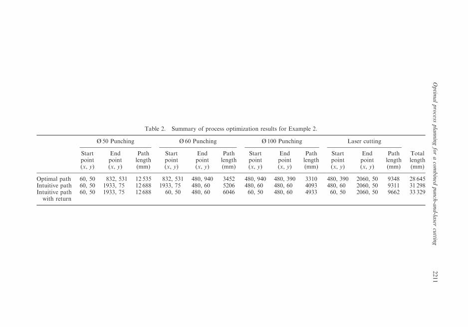
Table 2. Summary of process optimization results for Example 2.
Ø 50 Punching Ø 60 Punching Ø100 Punching Laser cutting
Totallength(mm)
Startpoint(x, y)
Endpoint(x, y)
Pathlength(mm)
Startpoint(x, y)
Endpoint(x, y)
Pathlength(mm)
Startpoint(x, y)
Endpoint(x, y)
Pathlength(mm)
Startpoint(x, y)
Endpoint(x, y)
Pathlength(mm)
Optimal path 60, 50 832, 531 12 535 832, 531 480, 940 3452 480, 940 480, 390 3310 480, 390 2060, 50 9348 28 645Intuitive path 60, 50 1933, 75 12 688 1933, 75 480, 60 5206 480, 60 480, 60 4093 480, 60 2060, 50 9311 31 298Intuitive pathwith return
60, 50 1933, 75 12 688 60, 50 480, 60 6046 60, 50 480, 60 4933 60, 50 2060, 50 9662 33 329
2211
Optim
alprocess
planningforacombined
punch-and-la
sercuttin
g
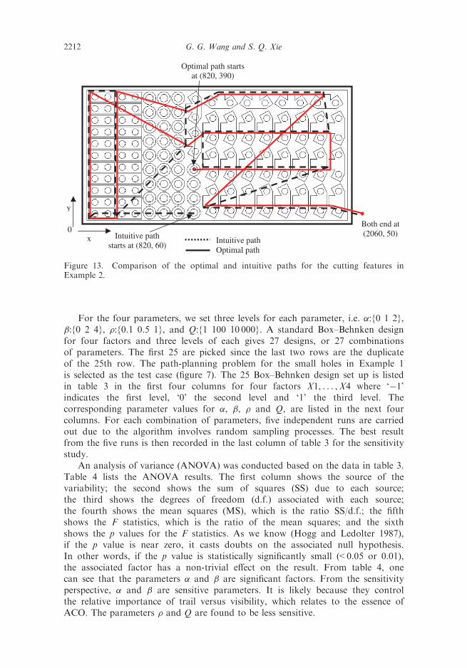
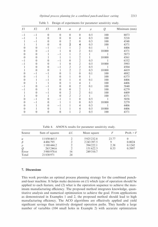
For the four parameters, we set three levels for each parameter, i.e. �:{0 1 2},�:{0 2 4}, �:{0.1 0.5 1}, and Q:{1 100 10 000}. A standard Box–Behnken designfor four factors and three levels of each gives 27 designs, or 27 combinationsof parameters. The first 25 are picked since the last two rows are the duplicateof the 25th row. The path-planning problem for the small holes in Example 1is selected as the test case (figure 7). The 25 Box–Behnken design set up is listedin table 3 in the first four columns for four factors X1, . . . ,X4 where ‘�1’indicates the first level, ‘0’ the second level and ‘1’ the third level. Thecorresponding parameter values for �, �, � and Q, are listed in the next fourcolumns. For each combination of parameters, five independent runs are carriedout due to the algorithm involves random sampling processes. The best resultfrom the five runs is then recorded in the last column of table 3 for the sensitivitystudy.
An analysis of variance (ANOVA) was conducted based on the data in table 3.Table 4 lists the ANOVA results. The first column shows the source of thevariability; the second shows the sum of squares (SS) due to each source;the third shows the degrees of freedom (d.f.) associated with each source;the fourth shows the mean squares (MS), which is the ratio SS/d.f.; the fifthshows the F statistics, which is the ratio of the mean squares; and the sixthshows the p values for the F statistics. As we know (Hogg and Ledolter 1987),if the p value is near zero, it casts doubts on the associated null hypothesis.In other words, if the p value is statistically significantly small (<0.05 or 0.01),the associated factor has a non-trivial effect on the result. From table 4, onecan see that the parameters � and � are significant factors. From the sensitivityperspective, � and � are sensitive parameters. It is likely because they controlthe relative importance of trail versus visibility, which relates to the essence ofACO. The parameters � and Q are found to be less sensitive.
Intuitive pathOptimal path
Optimal path startsat (820, 390)
Intuitive pathstarts at (820, 60)
x
y
0Both end at(2060, 50)
Figure 13. Comparison of the optimal and intuitive paths for the cutting features inExample 2.
2212 G. G. Wang and S. Q. Xie
7. Discussions
This work provides an optimal process planning strategy for the combined punch-and-laser machine. It helps make decisions on (1) which type of operation should beapplied to each feature, and (2) what is the operation sequence to achieve the max-imum manufacturing efficiency. The proposed method integrates knowledge, quan-titative analysis and numerical optimization to achieve the goal. From applicationsas demonstrated in Examples 1 and 2, the proposed method should lead to highmanufacturing efficiency. The ACO algorithms are effectively applied and yieldsignificant savings than intuitively designed operation paths. They handle a largenumber of variables (104 small holes in Example 2) with accurate optimization
Table 3. Design of experiments for parameter sensitivity study.
X1 X2 X3 X4 � � � Q Minimum (mm)
�1 �1 0 0 0 0 0.5 100 8073�1 1 0 0 0 4 0.5 100 52181 �1 0 0 2 0 0.5 100 45481 1 0 0 2 4 0.5 100 43710 0 �1 �1 1 2 0.1 1 44060 0 �1 1 1 2 0.1 10 000 43710 0 1 �1 1 2 1 1 58730 0 1 1 1 2 1 10 000 4561
�1 0 0 �1 0 2 0.5 1 6332�1 0 0 1 0 2 0.5 10 000 59931 0 0 �1 2 2 0.5 1 45041 0 0 1 2 2 0.5 10 000 44190 �1 �1 0 1 0 0.1 100 48820 �1 1 0 1 0 1 100 63750 1 �1 0 1 4 0.1 100 44060 1 1 0 1 4 1 100 4406
�1 0 �1 0 0 2 0.1 100 5840�1 0 1 0 0 2 1 100 62791 0 �1 0 2 2 0.1 100 44091 0 1 0 2 2 1 100 43710 �1 0 �1 1 0 0.5 1 50580 �1 0 1 1 0 0.5 10 000 52790 1 0 �1 1 4 0.5 1 44060 1 0 1 1 4 0.5 10 000 44060 0 0 0 1 2 0.5 100 4371
Table 4. ANOVA results for parameter sensitivity study.
Source Sum of squares d.f. Mean square F Prob.>F
� 11 850 465.5 2 5 925 232.8 23.77 0� 4 486 795 2 2 243 397.5 9 0.0024� 1 188 444.2 2 594 222.1 2.38 0.1242Q 263 244.6 2 131 622.3 0.53 0.5997Error 3 988 970.6 16 249 310.7Total 21 830 971 24
2213Optimal process planning for a combined punch-and-laser cutting

results. Through the sensitivity study guided by the theory of DoE, it is found for theACO algorithms the parameters � and � are sensitive parameters, while � and Q areless sensitive.
Moreover, the proposed strategy can be integrated with the CAN tool and theNC G-Code generation program. The proposed strategy can be implemented ascomputer programs to automate the decision making process. All the input informa-tion needed by the strategy includes only the geometry and machining parameterssuch as cutting speed, positioning speed, stroke speed, tool change time, and physicaland accuracy limitations. Geometric information can be retrieved from the CANtool and machining information can be entered once and stored. Upon finishing, thedetermined operation sequence can then be used to generate G-Code to drive thecombined punch-and-laser machine. The proposed strategy complements the currentCAN to G-Code path (Xie et al. 2004), which focuses mainly on the material utiliza-tion ratio. As a result, the maximum machining efficiency can be possibly achieved.Besides the punch-and-laser machine, the proposed strategy should be able to beapplied to other types of combination machines with slight modification.
It is well known that the common objective of nesting is to achieve the maximummaterial utilization ratio (Xie et al. 2004). It is observed in the study that the sheetmetal layout generated under this objective may lead to less efficient operationprocess, because such layouts tend to fit all the spaces available without consideringthe complexity of the final layout. From the operation efficiency perspective, it isbetter to move all the identical features close to each other to reduce the tool traversetime. For example in Example 2, it would improve the operation efficiency if all therings were laid out to the right of the clips. By doing so, all the small holes as well asall the cut contours, are close to each other and thus the entire tool travelling pathshould be shortened. A study on considering the operation efficiency in the optimalnesting process may be a worthwhile attempt.
Another observed issue relates to the size of a work batch. It is found that if thetotal number of an identical feature is too large, the ant algorithm may take too longto converge. In optimizing the path for 104 small holes in Example 2, the optimiza-tion process takes more than 10min to converge on a Pentium 2.6GHz desktopcomputer. Though one can run the proposed process planning programs includingthe optimization beforehand, it might be more attractive if the batch size is appro-priate so that the operator can run the process planning on-line. In addition, if thebatch size is too big, sometimes the tool has to travel back and forth in a large sheet,especially when the sheet layout does not consider the operation efficiency at all.On the other hand, if the batch size is too small, the overhead costs on moving tostarting points, path recording, programming, etc., may increase. A study on design-ing the appropriate batch size is thus needed.
8. Conclusions
This work proposes a systematic approach for optimal process planning of combinedpunch-and-laser machines by integrating knowledge, quantitative analysis andnumerical optimization. The ant colony optimization (ACO) algorithms are success-fully tailored and applied for the problem. Based on our literature search results,it seems that this work is the first endeavour in addressing the optimal processplanning for combined machines. The applications and comparisons demonstrate
2214 G. G. Wang and S. Q. Xie

the effectiveness and potential efficiency improvement by using the proposed meth-odology. The test results in section 5 show that the proposed methodology hasshortened tool travelling paths while comparing with the intuitive method andhence leads to improved machining efficiency. Moreover, the proposed methodcan be easily integrated with CAN and NC G-Code generation programs to achievefull automation. Sensitivity studies on the ant algorithm parameters should provideguidance to other applications. Future research topics are discussed as well.
Acknowledegment
Financial support from the Natural Science and Engineering Council (NSERC) ofCanada, and the University of Auckland, New Zealand, on this project is highlyappreciated.
References
Bredow, W., Machine tool with a laser beam cutting device. US Patent and Trademark Office,C. Behrens AG, US Patent No. 4335296, 1982.
Clark, S.C. and Carbone, V.T., Laser cutting head attachment for punch press. US Patent andTrademark Office, Houaille Industries, Inc., US, Patent No. 4201905, 1980.
Dorigo, M., Ant colony optimization, 2003. Available online at: http://www.aco-metaheuristic.org/publications.html (accessed December 2004).
Dorigo, M., Maniezzo, V. and Colorni, A., The ant system: optimization by a colony ofcooperating agents. IEEE Trans. Sys. Man Cyber. B, 1996, 26, 29–41.
Eberhart, R.C. and Kennedy, J., A new optimizer using particle swarm theory, in Proceedingsof the 6th Symposium MicroMachine and Human Science, Nagoya, Japan, 1995,pp. 39–43.
Endo, J., Ohba, S. and Anzai, T., Virtual manufacturing for sheet metal processing (develop-ment of scheduling simulator for small scale job shop). J. Mat. Proc. Tech., 1996, 60,191–196.
Gen, M. and Cheng, R.W., Genetic Algorithms and Engineering Design, 1997 (Wiley: NewYork).
Ghosh, S.K., Beitialarrangoitia, J.C. and Douglas, S.S., An automatic process-planningstrategy applied to a flexible two-dimensional cutting facility. J. Mat. Proc. Tech.,1993, 37, 61–81.
Glover, F. and Laguna, M., Tabu Search, 1996 (Kluwer: Dordrecht).Hogg, R.V. and Ledolter, J., Engineering Statistics, 1987 (Macmillan: England).Kalpakjian, S. and Schimid, S.R., Manufacturing Processes for Engineering Materials, 2003
(Upper Saddle River, NJ: Prentice Hall).Katayama, I., Compound machining apparatus. US Patent and Trademark Office, Murata
Kikai Kabushiki Kaisha, US, Patent No. 4873418, 1989a.Katayama, I., Compound machining apparatus. US Patent and Trademark Office, Murata
Kikai Kabushiki Kaisha, US, Patent No. 4833292, 1989b.Kirkpatrick, S., Gelatt, C.D. and Vecchi, M.P., Optimization by simulated annealing. Science,
1983, 220, 671–680.Klingel, H. and Doettling, J., Combination punch press and laser cutting machine with laser
beam generator mounted thereon. US Patent and Trademark Office, Trumpf GmbH &Co., US, Patent No. 4940880, 1990.
Li, W.D., Ong, S.K. and Nee, A.Y.C., Optimization of process plans using a constraint-basedtabu search approach. Int. J. Prod. Res., 2004, 42, 1955–1985.
Schey, J.A., Introduction to Manufacturing Processes, 2000 (Singapore: McGraw-Hill).Trumpf, Trumpf CNC Sheet Metal Machining Centre Technical Data, 2004 (Trumpf, Inc: CT,
USA.). Available online at: http://www.us.trumpf.com (accessed December 2004).
2215Optimal process planning for a combined punch-and-laser cutting

Ulrish, J., Combination punch press and laser machine. US Patent and Trademark Office,Lillbacka Jetair OY, US, Patent No. 6144009, 2000.
Xie, S.Q., Tu, Y.L., Liu, J.Q. and Zhou, Z.D., Integrated and concurrent approach forcompound sheet metal cutting and punching. Int. J. Prod. Res., 2001, 39, 1095–1112.
Xie, S.Q., Wang, G.G. and Liu, Y., Optimal nesting of two-dimensional irregular parts: anintegrated approach. Int. J. Prod. Res., 2004 (submitted).
2216 G. G. Wang and S. Q. Xie