Embed Size (px)
Citation preview

Aalborg University
Multimedia Programming Examination 2012 Medialogy 8th Semester (Aalborg, Esbjerg and Ballerup)
Question 1
Need to mention that n is the size of the array A. Need to notice that it is theta(n^2), not O(n^2) that they’re being asked to show. That is, that the worst-case running time is bounded from above and below by a quadratic function. For full marks, they need to give costs for each line and derive an expression for the total cost. Something along the lines of the following.

Question 2 Lots of possibilities. Can be evaluated by comparing with pattern in Gamma et al.
Question 3 a. (5 marks) Race condition is where interference occurs on a data-object because of two threads accessing it in an interleaved manner. The example they were shown was as follows:
In this situation, the ending balance can be wrong because Fru Jensen and Hr. Jensen access the same bank account in an interleaved manner where the account was not locked for each thread while it was accessing it. b. (5 marks)
i. Each of the two threads, plus10 and minus5, carries out three steps: 1. reads balance into variable b
2. calculates the new balance and stores this in b 3. writes the new balance from b back into balance
These three steps can be interleaved in various ways because there is no synchronisation. Let An be step n for plus10 and Bn be step n for minus5:
What matters is the relative order of A1, A3, B1 and B3. There are therefore 6 possibilities:
bal1 = a.getBalance();
bal1 = bal1 + 100
a.setBalance(bal1)
bal2 = a .getBalance();
bal2 = bal2 - 50;
a.setBalance(bal2);
System.out.println(a.getBalance());
Starting balance ofaccount, a, is 1000 kr
Fru Jensen withdraws 50 krHr. Jensen deposits 100 kr
What is the final balance?

A1 A3 B1 B3 = 105 A1 B1 A3 B3 = 95 A1 B1 B3 A3 = 110 B1 A1 A3 B3 = 95 B1 A1 B3 A3 = 110 B1 B3 A1 A3 = 105 There are therefore 3 possible outputs: 95, 110 and 105. (2 marks, 1 if one missing)
b.ii. There are a couple of options. (2 marks for one of the possible answers) 1. swapping line 31 with line 30
2. putting lines 13-18 inside a “synchronized” block with the balance variable locked for those lines.
b.iii. Two threads are being used, but not concurrently, since one blocks until the data becomes available again. In this sense, synchronisation removes concurrency. (1 mark) Question 4
a. (5 marks) TCP is a connection-based protocol that provides a reliable, bi-directional flow of data. TCP guarantees that all data sent will arrive in the right order. UDP sends independent datagrams and does not guarantee that all the data will arrive at the destination. Also, if the data does arrive, it is not guaranteed to be in the correct order.
UDP is faster than TCP because there is no overhead due to error-checking. (2 marks)
i. UDP (1); ii. TCP (1); iii. UDP (1) b. (5 marks, 1 for each part)
i. Server ii. Hello
iii. Hello to you too! iv. InputStream provides a stream of bytes. InputStreamReader turns a stream of bytes into a stream of characters. BufferedReader supports buffered reading of a character stream, so that, for example, you can read a whole line of characters in an atomic
v. Port number on which Server program listens for incoming connection requests.
Question 5 a. (5 marks)
Initial threads – running when the program starts, usually only one, the main thread. Event dispatch thread: Most code that interacts with the Swing framework runs on this thread
Worker threads: Background threads on which time-consuming processes are executed.
b. (5 marks, 1 for each part) i. BorderLayout. Has 5 regions: PAGE_START, PAGE_END, LINE_START, LINE_END, CENTER. A single component can be placed in each region. Addition of a second component to a region that already contains a component causes the first to be replaced by the second. CENTER region expands to fill space available. By default, components added to CENTER.
ii. text: JTextField; label: JLabel. iii. The GUI instance that is constructed in line 32.
iv. Listens for ActionEvents emitted by the text JTextField component and then runs the actionPerformed() method defined in line 25.
v. pack() formats the JFrame of the application ready for being made visible, determining the size and position of each component in the JFrame main window.
Question 6
a. (4 marks) There exist positive constants, c1, c2 and n0 such that, for all values of n greater than n0, 0 ≤ c1.g(n) ≤ f(n) ≤ c2.g(n). b. (4 marks)
If n0 = 3, c1 = 4 and c2 = 5, then we have 4n^2 ≤ 4n^2 + 3n ≤5n^2 for all n ≥ n0. c. (2 marks) O(n log n)
Question 7
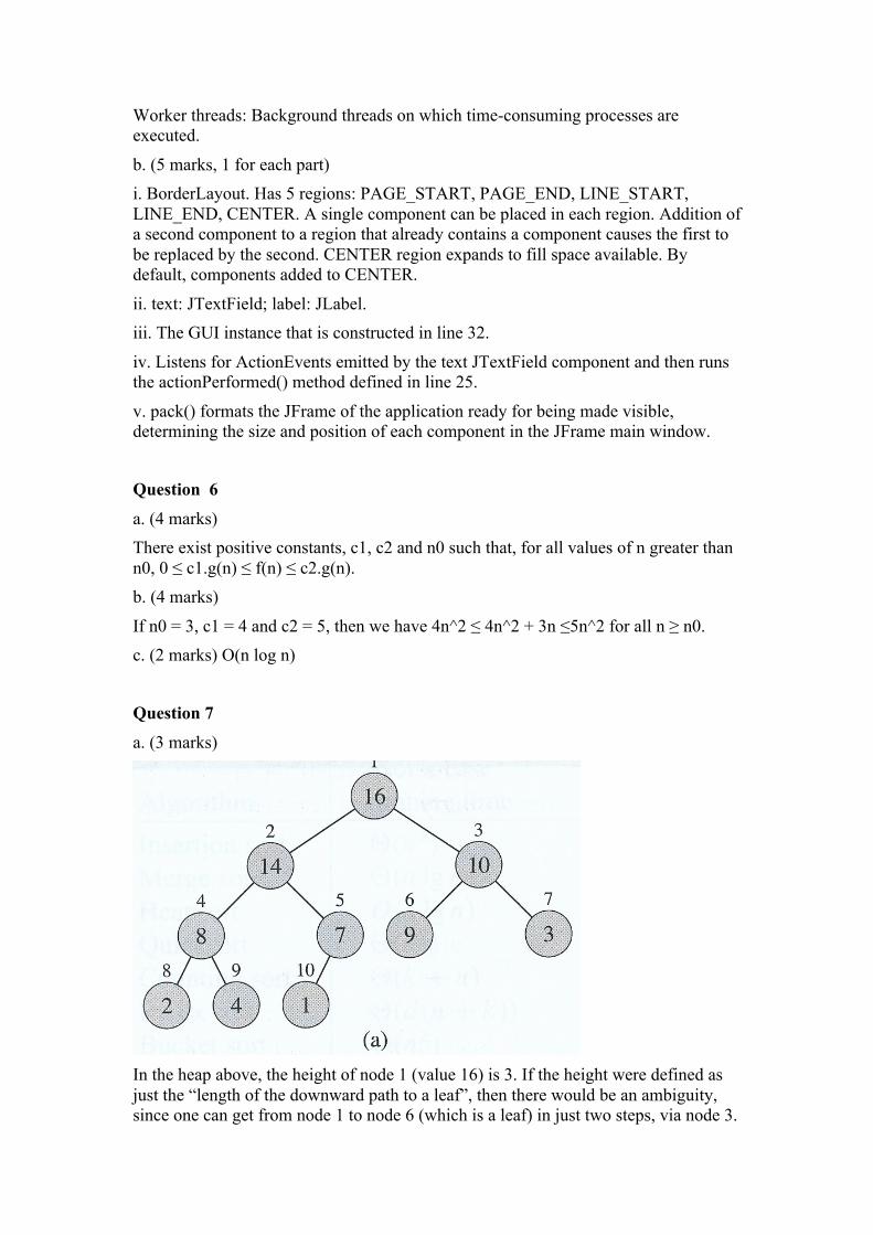
a. (3 marks)
In the heap above, the height of node 1 (value 16) is 3. If the height were defined as just the “length of the downward path to a leaf”, then there would be an ambiguity, since one can get from node 1 to node 6 (which is a leaf) in just two steps, via node 3.

This is why the height is defined as the longest downward path. In fact, because a heap is always acyclic, the word “simple” in the definition of height is redundant if the path is restricted to being downward. b. (3 marks)
Every node is greater than or equal to its parent. (1 mark)
(1 mark)
Stored as an array as follows
1 3 5 7 9 8 10 (1 mark)
c. (4 marks) Max-Heapify modifies the subtree rooted at node i of a heap so that the subtree satisfies the max-heap property. Starting at node i, Max-Heapify compares the value of this node with its two child nodes. This is a constant-time operation (lines 1-7). Having compared node i with its children and determined the largest, Max-Heapify switches the values in these three nodes so that they satisfy the max-heap property. This is also done in constant- time. If the largest value is one of the child nodes of i, then Max-Heapify is then called again on this child node in line 10. This continues until node i and its direct children satisfy the Max-Heap property. In the worst case, Max-Heapify is called on node i and a node at each level in the subtree rooted on node i. Since lines 1 – 8 take constant-time, the total worst-case running time is proportional to the height of node i, which is proportional to the log of the size of the subtree rooted on node i. Therefore the worst-case running time is O(lg n). Question 8
a, (5 marks) Both a stack and a queue support the dictionary operations INSERT and DELETE. INSERT on a stack (usually called PUSH) adds an element to the top of the stack. DELETE on a stack (usually called POP) removes the last element pushed onto the stack. A stack is therefore “last-in-first-out”. Both operations can be carried out in constant time. INSERT on a queue (ENQUEUE) adds an element to the end of the queue and DELETE (DEQUEUE) removes the element at the head of the queue. The element removed by DEQUEUE is the one that has been in the queue for the longest time. A queue is therefore “first-in-first-out”. Both operations can be done in constant time.
b. i. 15 (1 mark); 8 (1 mark)
ii. 3 (1 mark); 4 (1 mark) iii. 1 (1 mark)
Question 9
a. FPGA stands for Field Programmable Gate Array. i. (2 marks) What does Gate Array refer to?
FPGAs consist of programmable logic elements (‘gates’) that are arranged in a structured manner (‘arrays’).
ii. (2 marks) What does Field Programmable refer to? Most FPGAs can be programmed and reprogrammed by the designer/user ‘on the field’ (as opposed to factory programmed).
b. Examine Figure 1. i. (2 marks)What are the typical architectural elements in modern FPGAs?
Configurable elements (logic elements, memory blocks, arithmetic blocks, I/O blocks) Routing networks
Connection blocks Interconnect matrices
ii. (2 marks) What are their respective roles? Logic elements implement logic equations, registers and latches. Memory blocks are hardwired (a.k.a dedicated) internal storage; they can be used instead of using/combining configurable elements; arithmetic blocks are hardwired (a.k.a. dedicated) blocks that implement arithmetic operations (typically multipliers or DSP functions); they can be used instead of using/combining configurable elements. I/O blocks are used to receive/send signals from/to the peripherals connected to the FPGA.
Routing networks are used to transfer data between the configurable elements, across the FPGA chip.
Connection blocks connect the configurable elements to the routing networks. Interconnect matrices are used to connect the different parts of the routing network together. iii. (1 mark) What are the two architectural styles represented in the figure?
Figure 1, top: island-type; Figure 1, bottom: hierarchical-type c. (1 mark) Figure 2 shows a LUT-based configurable logic element. What is a LUT mostly used for? Look-Up-Tables (LUTs) are mostly used to implement logic equations.

Question 10 a. i. (1 mark) [b,c]: [un-‐blown fuse, blown fuse]; [d,e] : [un-‐grown antifuse, grown antifuse]; [f]: flash; [g]: SRAM ii. (1 mark) Fuse/antifuse: less sensitive to radiations (e.g. space applications) than SRAM, one time programmable (i.e. not reprogrammable) SRAM: usually at the forefront in terms of density (i.e. number of logic elements per area unit). Volatile: configuration is lost when the power is turned-‐off (need external device to store the configuration bitstream) Flash: Non-‐volatile, configuration stored inside the FPGA. Lower densities as compared to SRAM. iii. (1 mark) SRAM b. (2 marks) A hard-‐core (hardwired) microprocessor is physically integrated on the FPGA chip, next to the standard FPGA elements. A soft-‐core microprocessor is synthesized using the logic elements of the FPGA. c. (5 marks)
Design entry - Schematic based, Hardware Description Language (HDL) and
combinations hereof - Selection depends on the design and designer. - Schematics: visibility, hardware ‘thinking’ - HDL (VHDL, Verilog…): helps for complex design or algorithmic
‘thinking’ - Descending abstraction levels: Behavioral, RTL, Gate Functional Simulation (I) - Simulate the design entry - Verify functionality - Typically, does not take implementation/technology much into
account Synthesis - Transform the design entry (schematics, HDL code) into a circuit. - Circuit: is represented by means of a netlist

- Netlist: file that describes the logical elements and their interconnections.
- Hierarchical: the synthesis process generates netlists for each design element, including sub-‐elements
- Synthesis tools check code syntax and analyze the hierarchy of the design
- Can optimize a design for a specific target, if specified by the designer
- Descending abstraction levels: Behavioral synthesis, RTL synthesis, Logic Synthesis
- Depends on the capabilities of the tools
Functional Simulation (II)
- Simulate the behavior of the design, based on the netlist - Typically more accurate than the simulation that took place after
design entry (can take implementation/technology account)
Map, Place, Route
- Map: selects which type of resources should be used to implement the elements of the design (netlist). May need to split the design into sub-‐designs
- Place: selects which specific resources (and their locations inside the FPGA) should be used
- Route: find out how to interconnect the resources
- Map, Place, Route is often iterative, so as to optimize the design and fulfill the constraints
Timing simulation
- Now that the design has been synthesized, mapped, placed, and routed
- It is thus possible to simulate its behavior on the targeted FPGA
- More accurate than functional simulation I and II
- Detailed timing analysis can be performed (I/O to/from logic, propagation delays,…)
Might indicate that the designer must further optimize the synthesis, map, place, route steps, or the design entry (e.g., pipelining to reduce combinatorial delays)
Configuration

- Bitstream generation: generates a file that can be used for programming the FPGA. Bitstreams are typically formatted with Synch, ID, Data Frames, CRC,…
- Download and write to FPGA (or PROM…)
- Test: the more simulations and analysis have been performed during the flow, the higher probability that the implementation will work
Question 11 a. (2 marks) Optimization problems that decompose into overlapping subproblems. b. (3 marks) Because the same subproblems are solved multiple times. Cut-‐Rod calls itself over and over again with the same parameter values. For example, when n= 4, Cut-‐Rod(p,2) is called twice and Cut-‐Rod(p,1) is called 4 times.This can be seen in thefollowing recursion tree:
c. (5 marks)

Question 12
Line (10) specifes the kind of shader (i.e. a Surface Shader). (1 mark; if line (10) is not specified 1/2 mark for specifying lines (9) or (23))
This kind of shaders is supported on all devices, i.e. Windows PCs (1/2 mark), MacOS X computers (1/2 mark), Android devices (1/2 mark), and iOS devices (1/2 mark).
Line (4) has to be changed to: ”_SpecColor ("color of highlights", Color) = (1,1,1,1)” (1 mark for the line number, 1 mark for specifying that the identifier “_Specular” has to be changed; the specific name “_SpecColor” doesn’t matter because it can be looked up.)
Line (10) has to be changed to “#pragma surface func BlinnPhong”. (1 mark for the line number, 1 mark for specifying that “Lambert” has to be changed; the specific name “BlinnPhong” doesn’t matter because it can be looked up.)
Between lines (19) and (22) the line “o.Gloss = 1.0;” has to be added. (1 mark for any line number in the “func” function. 1 mark for specifying that an additional data member of “o” has to be changed to make highlights appear; the specific name and value doesn’t matter because it can be looked up.)
The disadvantage of per-vertex computation of specular highlights is the introduction of rendering artifacts (i.e. bad image quality; in particular for small highlights and coarse meshes). (1 mark)
One solution is to compute highlights per fragment (i.e. per pixel) (i.e. in the “func” function). Other solutions are to render larger highlights, or no highlights at all, or to use finer meshes, etc. (1 mark for any solution)
The implied disadvantage of computing highlights per fragment or the use of finer meshes is decreased rendering performance; the disadvantage of larger highlights or no highlights at all, is the absence of small highlights; etc. (1 mark for any disadvantage corresponding to the provided solution)