Embed Size (px)
Citation preview
7/25/2019 A9110E UBTS Commissioning
http://slidepdf.com/reader/full/a9110e-ubts-commissioning 1/74
Alcatel BSS
A9110-E BTS Commissioning
Manual
BTS Document
Commissioning Manual
Release B9
3BK 17422 3081 RJZZA Ed.02

7/25/2019 A9110E UBTS Commissioning
http://slidepdf.com/reader/full/a9110e-ubts-commissioning 2/74
Status RELEASED
Short title COM
All rights reserved. Passing on and copying of this document, useand communication of its contents not permitted without writtenauthorization from Alcatel/Evolium.
BLANK PAGE BREAK
2 / 74 3BK 17422 3081 RJZZA Ed.02
7/25/2019 A9110E UBTS Commissioning
http://slidepdf.com/reader/full/a9110e-ubts-commissioning 3/74
Contents
Contents
Preface . . . . . . . . . . . . . . . . . . . . . . . . . . . . . . . . . . . . . . . . . . . . . . . . . . . . . . . . . . . . . . . . . . . . . . . . . . . . . . . . . . . . . . . . 7
1 General Information . . . . . . . . . . . . . . . . . . . . . . . . . . . . . . . . . . . . . . . . . . . . . . . . . . . . . . . . . . . . . . . . . . . . . . . 9
1.1 Hardware Description . . . . . . . . . . . . . . . . . . . . . . . . . . . . . . . . . . . . . . . . . . . . . . . . . . . . . . . . . . . . . . 101.1.1 Configurations . . . . . . . . . . . . . . . . . . . . . . . . . . . . . . . . . . . . . . . . . . . . . . . . . . . . . . . . . 101.1.2 Weight and Dimensions . . . . . . . . . . . . . . . . . . . . . . . . . . . . . . . . . . . . . . . . . . . . . . . . . 13
1.2 Restrictions . . . . . . . . . . . . . . . . . . . . . . . . . . . . . . . . . . . . . . . . . . . . . . . . . . . . . . . . . . . . . . . . . . . . . . . 131.3 Prerequisites . . . . . . . . . . . . . . . . . . . . . . . . . . . . . . . . . . . . . . . . . . . . . . . . . . . . . . . . . . . . . . . . . . . . . . 131.4 Initial State . . . . . . . . . . . . . . . . . . . . . . . . . . . . . . . . . . . . . . . . . . . . . . . . . . . . . . . . . . . . . . . . . . . . . . . . 131.5 Final State . . . . . . . . . . . . . . . . . . . . . . . . . . . . . . . . . . . . . . . . . . . . . . . . . . . . . . . . . . . . . . . . . . . . . . . . 131.6 Operating Principle . . . . . . . . . . . . . . . . . . . . . . . . . . . . . . . . . . . . . . . . . . . . . . . . . . . . . . . . . . . . . . . . 151.7 Time Schedule . . . . . . . . . . . . . . . . . . . . . . . . . . . . . . . . . . . . . . . . . . . . . . . . . . . . . . . . . . . . . . . . . . . . 161.8 Information Required . . . . . . . . . . . . . . . . . . . . . . . . . . . . . . . . . . . . . . . . . . . . . . . . . . . . . . . . . . . . . . . 171.9 Conventions . . . . . . . . . . . . . . . . . . . . . . . . . . . . . . . . . . . . . . . . . . . . . . . . . . . . . . . . . . . . . . . . . . . . . . . 17
2 Preliminary Checks . . . . . . . . . . . . . . . . . . . . . . . . . . . . . . . . . . . . . . . . . . . . . . . . . . . . . . . . . . . . . . . . . . . . . . . . 19
2.1 Before Going to the Site . . . . . . . . . . . . . . . . . . . . . . . . . . . . . . . . . . . . . . . . . . . . . . . . . . . . . . . . . . . . 202.2 Before You Start (On Arrival at the Site) . . . . . . . . . . . . . . . . . . . . . . . . . . . . . . . . . . . . . . . . . . . . . . 20
3 Installing the Micro - BTS Units . . . . . . . . . . . . . . . . . . . . . . . . . . . . . . . . . . . . . . . . . . . . . . . . . . . . . . . . . . . . 21
3.1 Case A: Installation With the Manual Lift . . . . . . . . . . . . . . . . . . . . . . . . . . . . . . . . . . . . . . . . . . . . . 223.2 Case B: Installation With the Crane . . . . . . . . . . . . . . . . . . . . . . . . . . . . . . . . . . . . . . . . . . . . . . . . . . 26
3.2.1 Specific Safety Instructions for Craning . . . . . . . . . . . . . . . . . . . . . . . . . . . . . . . . . . . 263.2.2 Installation of the Crane on MOFRA . . . . . . . . . . . . . . . . . . . . . . . . . . . . . . . . . . . . . . 263.2.3 Preparation for Craning . . . . . . . . . . . . . . . . . . . . . . . . . . . . . . . . . . . . . . . . . . . . . . . . . 283.2.4 Installing the Micro-BTS on MOCO . . . . . . . . . . . . . . . . . . . . . . . . . . . . . . . . . . . . . . . 29
4 Making the Connections to the BTS . . . . . . . . . . . . . . . . . . . . . . . . . . . . . . . . . . . . . . . . . . . . . . . . . . . . . . . . 33
4.1 OPTION: Installing the Integrated Antenna . . . . . . . . . . . . . . . . . . . . . . . . . . . . . . . . . . . . . . . . . . . 344.2 OPTION: Installing the VSWR Detector . . . . . . . . . . . . . . . . . . . . . . . . . . . . . . . . . . . . . . . . . . . . . . 35
4.2.1 Mechanics . . . . . . . . . . . . . . . . . . . . . . . . . . . . . . . . . . . . . . . . . . . . . . . . . . . . . . . . . . . . . 354.2.2 Fixing the VSWR Detector . . . . . . . . . . . . . . . . . . . . . . . . . . . . . . . . . . . . . . . . . . . . . . 364.2.3 Connecting the Cables . . . . . . . . . . . . . . . . . . . . . . . . . . . . . . . . . . . . . . . . . . . . . . . . . . 37
4.3 Making the Connections to the BTS . . . . . . . . . . . . . . . . . . . . . . . . . . . . . . . . . . . . . . . . . . . . . . . . . 38
5 Checking Power Supply and Powering Up . . . . . . . . . . . . . . . . . . . . . . . . . . . . . . . . . . . . . . . . . . . . . . . . . . 41
5.1 Case 1: A9110-E BTS Without SSC . . . . . . . . . . . . . . . . . . . . . . . . . . . . . . . . . . . . . . . . . . . . . . . . . 425.2 Case 2: A9110-E BTS With SSC . . . . . . . . . . . . . . . . . . . . . . . . . . . . . . . . . . . . . . . . . . . . . . . . . . . . 42
6 Commissioning Tests . . . . . . . . . . . . . . . . . . . . . . . . . . . . . . . . . . . . . . . . . . . . . . . . . . . . . . . . . . . . . . . . . . . . . 45
6.1 BTS Software Downloading . . . . . . . . . . . . . . . . . . . . . . . . . . . . . . . . . . . . . . . . . . . . . . . . . . . . . . . . . 466.2 BTS Initialization . . . . . . . . . . . . . . . . . . . . . . . . . . . . . . . . . . . . . . . . . . . . . . . . . . . . . . . . . . . . . . . . . . . 486.3 Performing BTS Inventory . . . . . . . . . . . . . . . . . . . . . . . . . . . . . . . . . . . . . . . . . . . . . . . . . . . . . . . . . . 49
6.4 Setting and Checking the External Alarms . . . . . . . . . . . . . . . . . . . . . . . . . . . . . . . . . . . . . . . . . . . 496.4.1 Set and Check the Alarm Mapping . . . . . . . . . . . . . . . . . . . . . . . . . . . . . . . . . . . . . . . 496.4.2 Test the External Alarms . . . . . . . . . . . . . . . . . . . . . . . . . . . . . . . . . . . . . . . . . . . . . . . . 50
6.5 Checking the Status of Modules . . . . . . . . . . . . . . . . . . . . . . . . . . . . . . . . . . . . . . . . . . . . . . . . . . . . . 526.6 VSWR Check . . . . . . . . . . . . . . . . . . . . . . . . . . . . . . . . . . . . . . . . . . . . . . . . . . . . . . . . . . . . . . . . . . . . . 526.7 Abis Loop Test . . . . . . . . . . . . . . . . . . . . . . . . . . . . . . . . . . . . . . . . . . . . . . . . . . . . . . . . . . . . . . . . . . . . 556.8 End of Commissioning . . . . . . . . . . . . . . . . . . . . . . . . . . . . . . . . . . . . . . . . . . . . . . . . . . . . . . . . . . . . . 55
7 Setting Transmission Module Parameters . . . . . . . . . . . . . . . . . . . . . . . . . . . . . . . . . . . . . . . . . . . . . . . . . . 57
8 Connecting to the BSC . . . . . . . . . . . . . . . . . . . . . . . . . . . . . . . . . . . . . . . . . . . . . . . . . . . . . . . . . . . . . . . . . . . . 59
9 Finishing Commissioning . . . . . . . . . . . . . . . . . . . . . . . . . . . . . . . . . . . . . . . . . . . . . . . . . . . . . . . . . . . . . . . . . . 61
Appendix A : Abbreviations . . . . . . . . . . . . . . . . . . . . . . . . . . . . . . . . . . . . . . . . . . . . . . . . . . . . . . . . . . . . . . . . . . . . 63
Appendix B : List of Items Required . . . . . . . . . . . . . . . . . . . . . . . . . . . . . . . . . . . . . . . . . . . . . . . . . . . . . . . . . . . . 65
3BK 17422 3081 RJZZA Ed.02 3 / 74

7/25/2019 A9110E UBTS Commissioning
http://slidepdf.com/reader/full/a9110e-ubts-commissioning 4/74
Contents
Appendix C : Description of ABISCO and ACCO Boards . . . . . . . . . . . . . . . . . . . . . . . . . . . . . . . . . . . . . . . . . 67
Appendix D : Antenna Port and External Alarm Mapping Rules . . . . . . . . . . . . . . . . . . . . . . . . . . . . . . . . . . 71
4 / 74 3BK 17422 3081 RJZZA Ed.02

7/25/2019 A9110E UBTS Commissioning
http://slidepdf.com/reader/full/a9110e-ubts-commissioning 5/74
Figures
Figures
Figure 1: Example of 6 Modules with Single Antenna . . . . . . . . . . . . . . . . . . . . . . . . . . . . . . . . . . . . . . . . . . . . . . . 10
Figure 2: Example Low-Loss Configuration With Antenna Diversity (6 sectors) . . . . . . . . . . . . . . . . . . . . . . . . 11
Figure 3: Evolium A9110-E Pure Configuration (Maximum 6 Evolium A9110-E Modules, 12 TREs) . . . . . . 11
Figure 4: Evolium A9110-E / Evolium A9110 Mixed Configuration (5 Modules: 4 Evolium A9110-E +1 EvoliumA9110, 10 TREs in total) . . . . . . . . . . . . . . . . . . . . . . . . . . . . . . . . . . . . . . . . . . . . . . . . . . . . . . . . . . . . . . . . 12
Figure 5: Evolium A9110-E / Evolium A9110 Mixed Configuration (3 Modules: 1 Evolium A9110-E + 2 EvoliumA9110, 6 TREs in total ) . . . . . . . . . . . . . . . . . . . . . . . . . . . . . . . . . . . . . . . . . . . . . . . . . . . . . . . . . . . . . . . . 12
Figure 6: Example of A9110-E BTS ( Maximum 6 Evolium A9110-E Configuration With Cover ) . . . . . . . . . 14
Figure 7: Example of A9110-E BTS (3 modules with SSC Option) . . . . . . . . . . . . . . . . . . . . . . . . . . . . . . . . . . . . 14
Figure 8: Installation and Arrangement of the Threaded Bolt . . . . . . . . . . . . . . . . . . . . . . . . . . . . . . . . . . . . . . . . . 22
Figure 9: Installation of the Handwheel . . . . . . . . . . . . . . . . . . . . . . . . . . . . . . . . . . . . . . . . . . . . . . . . . . . . . . . . . . . . 23
Figure 10: Installing the Gallows . . . . . . . . . . . . . . . . . . . . . . . . . . . . . . . . . . . . . . . . . . . . . . . . . . . . . . . . . . . . . . . . . . 23Figure 11: Installing the BTS Handle . . . . . . . . . . . . . . . . . . . . . . . . . . . . . . . . . . . . . . . . . . . . . . . . . . . . . . . . . . . . . . 24
Figure 12: BTS Handle Fixed on the Module . . . . . . . . . . . . . . . . . . . . . . . . . . . . . . . . . . . . . . . . . . . . . . . . . . . . . . . 24
Figure 13: Putting the A9110-E BTS in Position . . . . . . . . . . . . . . . . . . . . . . . . . . . . . . . . . . . . . . . . . . . . . . . . . . . . 25
Figure 14: Fixing the Unit . . . . . . . . . . . . . . . . . . . . . . . . . . . . . . . . . . . . . . . . . . . . . . . . . . . . . . . . . . . . . . . . . . . . . . . . . 25
Figure 15: Mounting the Lifting Ring . . . . . . . . . . . . . . . . . . . . . . . . . . . . . . . . . . . . . . . . . . . . . . . . . . . . . . . . . . . . . . . 26
Figure 16: Installing the Crane . . . . . . . . . . . . . . . . . . . . . . . . . . . . . . . . . . . . . . . . . . . . . . . . . . . . . . . . . . . . . . . . . . . . 27
Figure 17: ACout BTS Power Connector of ACCO Board is Used to Power the Crane . . . . . . . . . . . . . . . . . . 28
Figure 18: Lifting and Plugging in the Micro-BTS Unit . . . . . . . . . . . . . . . . . . . . . . . . . . . . . . . . . . . . . . . . . . . . . . . 29
Figure 19: Fixing the Micro-BTS to MOCO . . . . . . . . . . . . . . . . . . . . . . . . . . . . . . . . . . . . . . . . . . . . . . . . . . . . . . . . . 31
Figure 20: Installation of Integrated Antenna (GSM and DCS) . . . . . . . . . . . . . . . . . . . . . . . . . . . . . . . . . . . . . . . 34
Figure 21: The VSWR Detector . . . . . . . . . . . . . . . . . . . . . . . . . . . . . . . . . . . . . . . . . . . . . . . . . . . . . . . . . . . . . . . . . . . 35
Figure 22: VSWR Detector - RF Installation . . . . . . . . . . . . . . . . . . . . . . . . . . . . . . . . . . . . . . . . . . . . . . . . . . . . . . . . 36
Figure 23: Connecting the ALARM / VCC Cables . . . . . . . . . . . . . . . . . . . . . . . . . . . . . . . . . . . . . . . . . . . . . . . . . . . 37
Figure 24: Connection of IEB PG 11 Glands to COBO for All Modules . . . . . . . . . . . . . . . . . . . . . . . . . . . . . . . . 39
Figure 25: ACCO Board . . . . . . . . . . . . . . . . . . . . . . . . . . . . . . . . . . . . . . . . . . . . . . . . . . . . . . . . . . . . . . . . . . . . . . . . . . 43
Figure 26: SSC Switch Configuration . . . . . . . . . . . . . . . . . . . . . . . . . . . . . . . . . . . . . . . . . . . . . . . . . . . . . . . . . . . . . . 43
Figure 27: “ Sector Mapping Micro BTS“ Window . . . . . . . . . . . . . . . . . . . . . . . . . . . . . . . . . . . . . . . . . . . . . . . . . . . 48
Figure 28: ABISCO Board for A9110-E . . . . . . . . . . . . . . . . . . . . . . . . . . . . . . . . . . . . . . . . . . . . . . . . . . . . . . . . . . . . 67
Figure 29: ABISCO Board for A9110 . . . . . . . . . . . . . . . . . . . . . . . . . . . . . . . . . . . . . . . . . . . . . . . . . . . . . . . . . . . . . . 68
Figure 30: Connectors and LEDs on ABISCO . . . . . . . . . . . . . . . . . . . . . . . . . . . . . . . . . . . . . . . . . . . . . . . . . . . . . . 69
Figure 31: Mechanical Drawing of ACCO . . . . . . . . . . . . . . . . . . . . . . . . . . . . . . . . . . . . . . . . . . . . . . . . . . . . . . . . . . 70
Figure 32: Electrical Drawing of ACCO . . . . . . . . . . . . . . . . . . . . . . . . . . . . . . . . . . . . . . . . . . . . . . . . . . . . . . . . . . . . 70
Figure 33: “ Application part “ Window . . . . . . . . . . . . . . . . . . . . . . . . . . . . . . . . . . . . . . . . . . . . . . . . . . . . . . . . . . . . . 74
3BK 17422 3081 RJZZA Ed.02 5 / 74

7/25/2019 A9110E UBTS Commissioning
http://slidepdf.com/reader/full/a9110e-ubts-commissioning 6/74
Figures
6 / 74 3BK 17422 3081 RJZZA Ed.02

7/25/2019 A9110E UBTS Commissioning
http://slidepdf.com/reader/full/a9110e-ubts-commissioning 7/74
Preface
Preface
Purpose This document describes how to commission an Alcatel A9110-E micro BTS.This document applies to operational BSS, release B9.
What’s New In Edition 02
Editorial improvement.
In Edition 01
Creation in B9.
Audience This document is intended for:
Site administrators
Supervisors
Project managers
Field service technicians
Occasional users.
Assumed Knowledge The personnel involved must be familiar with:
ALCATEL Operation & Maintenance (O&M) concepts for the Base Station
Subsystem (BSS)
Commissioning tools
Personal Computers (PCs) using the Windows 2000/XP environment.
3BK 17422 3081 RJZZA Ed.02 7 / 74
7/25/2019 A9110E UBTS Commissioning
http://slidepdf.com/reader/full/a9110e-ubts-commissioning 8/74
Preface
8 / 74 3BK 17422 3081 RJZZA Ed.02

7/25/2019 A9110E UBTS Commissioning
http://slidepdf.com/reader/full/a9110e-ubts-commissioning 9/74
1 General Information
1 General Information
This chapter provides general information concerning the operating principleand requirements of the procedure:
Hardware description
Prerequisites
Restrictions
Initial state
Final state
Tasks sequences
Time schedule
Information required
Conventions.
3BK 17422 3081 RJZZA Ed.02 9 / 74

7/25/2019 A9110E UBTS Commissioning
http://slidepdf.com/reader/full/a9110e-ubts-commissioning 10/74
1 General Information
1.1 Hardware Description
1.1.1 Configurations
With this product, one BTS comprises up to six units of two TRX, in a
hierarchical interconnection.
Only one of these units handles the Abis lines; this unit called the master,
the other units called slaves.
A unit can have one antenna output (3.2 W/TRX max. power) or two
antenna outputs (7 W/TRX max. power).
One lower slave cannot be equipped because of 12 TRX limitation!In the following exemples the Slave 22 is eliminated, but depending on siteconfiguration, you can have maximum 3 lower slave units on the 4 possiblepositions: Slave11, Slave12, Slave 21, Slave 22.
Figure 1: Example of 6 Modules with Single Antenna
10 / 74 3BK 17422 3081 RJZZA Ed.02

7/25/2019 A9110E UBTS Commissioning
http://slidepdf.com/reader/full/a9110e-ubts-commissioning 11/74
1 General Information
Figure 2: Example Low-Loss Configuration With Antenna Diversity (6 sectors)
The following rules are defined for pure Evolium A9110-E and EvoliumA9110/Evolium A9110-E mixed configurations:
Maximum 6 modules are allowed for Evolium A9110-E.
Maximum 3 hierarchy levels are allowed (Master, Upper Slave, Lower Slave)
M5M
Master
M5M
Lower Slave 11
M5M
Lower Slave 12
M5M
Lower Slave 21
M5M
Upper Slave 1
M5M
Upper Slave 2
Figure 3: Evolium A9110-E Pure Configuration (Maximum 6 Evolium A9110-E Modules, 12 TREs)
Evolium A9110 module allowed only as upper slave, no lower slaves can
connect to it.
3BK 17422 3081 RJZZA Ed.02 11 / 74

7/25/2019 A9110E UBTS Commissioning
http://slidepdf.com/reader/full/a9110e-ubts-commissioning 12/74
1 General Information
M5M
Master
M5M
Lower Slave 11
M5M
Lower Slave 12
M5M
Upper Slave 1
M4M
Upper Slave 2
Figure 4: Evolium A9110-E / Evolium A9110 Mixed Configuration (5 Modules: 4 Evolium A9110-E +1 Evolium A9110, 10 TREs in total)
M5M
Master
M4M
Upper Slave 1
M4M
Upper Slave 2
Figure 5: Evolium A9110-E / Evolium A9110 Mixed Configuration (3 Modules: 1 Evolium A9110-E + 2 Evolium A9110, 6 TREs in total )
12 / 74 3BK 17422 3081 RJZZA Ed.02
7/25/2019 A9110E UBTS Commissioning
http://slidepdf.com/reader/full/a9110e-ubts-commissioning 13/74
1 General Information
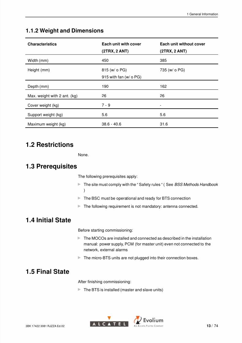
1.1.2 Weight and Dimensions
Characteristics Each unit with cover
(2TRX, 2 ANT)
Each unit without cover
(2TRX, 2 ANT)
Width (mm) 450 385
Height (mm) 815 (w/ o PG)
915 with fan (w/ o PG)
735 (w/ o PG)
Depth (mm) 190 162
Max. weight with 2 ant. (kg) 26 26
Cover weight (kg) 7 - 9 -
Support weight (kg) 5.6 5.6
Maximum weight (kg) 38.6 - 40.6 31.6
1.2 Restrictions
None.
1.3 Prerequisites
The following prerequisites apply:
The site must comply with the “ Safety rules “ ( See BSS Methods Handbook
)
The BSC must be operational and ready for BTS connection
The following requirement is not mandatory: antenna connected.
1.4 Initial State
Before starting commissioning:
The MOCOs are installed and connected as described in the installationmanual: power supply, PCM (for master unit) even not connected to the
network, external alarms
The micro-BTS units are not plugged into their connection boxes.
1.5 Final State
After finishing commissioning:
The BTS is installed (master and slave units)
3BK 17422 3081 RJZZA Ed.02 13 / 74

7/25/2019 A9110E UBTS Commissioning
http://slidepdf.com/reader/full/a9110e-ubts-commissioning 14/74
1 General Information
The BTS is commissioned, powered up and connected to the BSC via a
PCM interface ready for network integration
Integrated antenna option: integrated antennas are installed on all units
Antennas present: the antennas have been connected
Antennas absent: the tests have been carried out under load.
Figure 6: Example of A9110-E BTS ( Maximum 6 Evolium A9110-E Configuration With Cover )
Customer Alarm Box
Alarm pointsfor Customer
230 VAC
1.5 m
MASTER SLAVE 2 SLAVE 1
Ground
Plate
Wire braid
Figure 7: Example of A9110-E BTS (3 modules with SSC Option)
14 / 74 3BK 17422 3081 RJZZA Ed.02
7/25/2019 A9110E UBTS Commissioning
http://slidepdf.com/reader/full/a9110e-ubts-commissioning 15/74
1 General Information
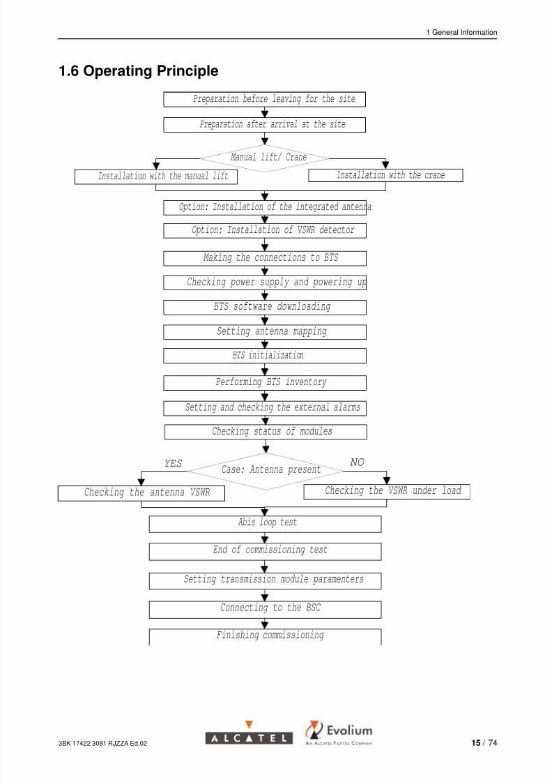
1.6 Operating Principle
Preparation before leaving for the site
Preparation after arrival at the site
Manual lift/ Crane
Installation with the crane
Option: Installation of the integrated antenna
Option: Installation of VSWR detector
Making the connections to BTS
Checking power supply and powering up
BTS software downloading
Setting antenna mapping
BTS initialization
Performing BTS inventory
Setting and checking the external alarms
Checking status of modules
Case: Antenna present
Checking the VSWR under load
Abis loop test
End of commissioning test
Setting transmission module paramenters
Connecting to the BSC
Finishing commissioning
Checking the antenna VSWR
YES NO
Installation with the manual lift
3BK 17422 3081 RJZZA Ed.02 15 / 74
7/25/2019 A9110E UBTS Commissioning
http://slidepdf.com/reader/full/a9110e-ubts-commissioning 16/74
1 General Information
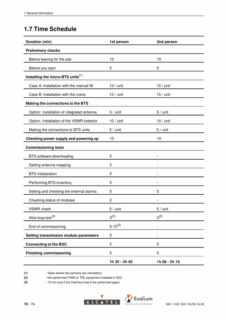
1.7 Time Schedule
Duration (min) 1st person 2nd person
Preliminary checks
Before leaving for the site 10 10
Before you start 5 5
Installing the micro-BTS units(1)
Case A: Installation with the manual lift 10 / unit 10 / unit
Case B: Installation with the crane 15 / unit 15 / unit
Making the connections to the BTS
Option: Installation of integrated antenna 5 / unit 5 / unit
Option: Installation of the VSWR detector 10 / unit 10 / unit
Making the connections to BTS units 5 / unit 5 / unit
Checking power supply and powering up 10 10
Commissioning tests
BTS software downloading 5 -
Setting antenna mapping 2 -
BTS initialization 5 -
Performing BTS inventory 5 -
Setting and checking the external alarms 5 5
Checking status of modules 2 -
VSWR check 5 / unit 5 / unit
Abis loop test(2) 3(2) 3(2)
End of commissioning 5-10(3) -
Setting transmission module parameters 5 -
Connecting to the BSC 5 5
Finishing commissioning 5 5
1h 32 - 2h 50 1h 08 - 2h 15
(1) : Tasks where two persons are mandatory
(2) : Not performed if MW or TNL equipment installed in SSC(3) : 10 min only if the inventory has to be performed again
16 / 74 3BK 17422 3081 RJZZA Ed.02
7/25/2019 A9110E UBTS Commissioning
http://slidepdf.com/reader/full/a9110e-ubts-commissioning 17/74
1 General Information
The times given are based on technical constraints, not taking into accountsafety considerations.
1.8 Information Required
Site Position of breakers on the customer’s power panel
If DDF cabled: position of PCM cables (Abis1, Abis2) on the DDF side.
Equipment configuration Configuration of the BTS (number of units, type: Evolium A9110/Evolium
A9110-E)
Configuration of sectors and number of MTREs per sector
Mapping table correlating logical and physical BTS sectors
If DDF installed: external alarm mapping and position of alarm wires on
the DDF side
If SSC option: customer external alarm mapping (other than SSC external
alarms).
Other Software version
Test frequencies
Transmission configuration
Qmux address
OML TS and signalling rate (optional).
Antennas connected or not.
1.9 Conventions
The following list gives the conventions used in this document:
Press [ Enter ] means press the Enter key
Click [ OK ] means click the button OK with the mouse
Operator input is indicated after a double right-pointing arrow in Courier font
Operator input
To describe a menu path, the menu options are linked as follows:
Tools ⇒ Options ⇒ Printer ⇒...
A message is indicated in Courier font:
Message
3BK 17422 3081 RJZZA Ed.02 17 / 74

7/25/2019 A9110E UBTS Commissioning
http://slidepdf.com/reader/full/a9110e-ubts-commissioning 18/74
1 General Information
18 / 74 3BK 17422 3081 RJZZA Ed.02
7/25/2019 A9110E UBTS Commissioning
http://slidepdf.com/reader/full/a9110e-ubts-commissioning 19/74
2 Preliminary Checks
2 Preliminary Checks
This chapter describes the preparation of the operation in two steps:
At base
On arrival at the site.
3BK 17422 3081 RJZZA Ed.02 19 / 74
7/25/2019 A9110E UBTS Commissioning
http://slidepdf.com/reader/full/a9110e-ubts-commissioning 20/74
2 Preliminary Checks
2.1 Before Going to the Site
Check prerequisites fulfillment See Prerequisites (Section 1.3) .
Check availability of information
required
See Information Required (Section 1.8) .
Check availability of documentation See List of Documents Required ( in section B ) .
Check availability of tools See Tools Required ( in section B ) , refer to the ”Toolscatalogue ” for content checking.
Verify the calibration label when indicated in Tools Required ( in section B ) .
Check availability and version ofsoftware
See List of Software Required ( in section B ) ; refer to thecorresponding documents for checking the SW version.
2.2 Before You Start (On Arrival at the Site)
Check applicable notification list andOperation Instructions
Refer to Applicable Notifications List (ITL) for checking ifnotifications have to applied during the operation.
Refer to Applicable Operation Instructions List (IO) forchecking if operation instructions have to applied.
Check that safety instructions areapplied
Refer to BSS Methods Handbook for checking that safetyprecautions have been taken into accordance with safety
instructions.
Read instructions to be applied in caseof anomaly
Refer to BSS methods Handbook for instructions.
Complete premises inspection form Refer to “ BSS site premises inspection, post handover “ andcomplete “ Premises inspection form ” (CEL).
Fill in completion check list Complete the header field of the CCL (See CompletionCheck List)
In particular, see tools catalogue and note downmeasurement accuracy when indicated in tool kit list
(appendix)
The CCL is completed as each installation instruction iscarried out.
Check the antistatic wrist strap Check that the resistance of the antistatic wrist strap isgreater than 1M .
Connect the antistatic wrist strap to rack earth.
Check availability of Alcatel kits See List of Items Required (Section B) .
20 / 74 3BK 17422 3081 RJZZA Ed.02

7/25/2019 A9110E UBTS Commissioning
http://slidepdf.com/reader/full/a9110e-ubts-commissioning 21/74
3 Installing the Micro - BTS Units
3 Installing the Micro - BTS Units
This chapter describes the procedure for fixing the micro BTS on MOFRA.
Before the installation of the BTS units, check the lead seal.If damaged, make a note in the CCL.
The installation procedure is the same for master and slave units.
Do not work under power.Open the circuit breakers to be sure that the power supply is disconnected.For an installation with SSC: Check that the " Battery back-up " is OFF (redLED is lit) !!! (in the case of battery back-up there is 288 V DC on the BTSconnector and the crane will be damaged!!!)
3BK 17422 3081 RJZZA Ed.02 21 / 74
7/25/2019 A9110E UBTS Commissioning
http://slidepdf.com/reader/full/a9110e-ubts-commissioning 22/74
3 Installing the Micro - BTS Units
3.1 Case A: Installation With the Manual Lift
Purpose To install the BTS on the MOCO.
Preparation 1. Open the front cover to reveal the MOCO (with cover option)
2. Remove the COBO protection cover (3BK 08586 AA).
3. Remove the bottom protection cover of the micro-BTS unit (3BK 08555 AA).
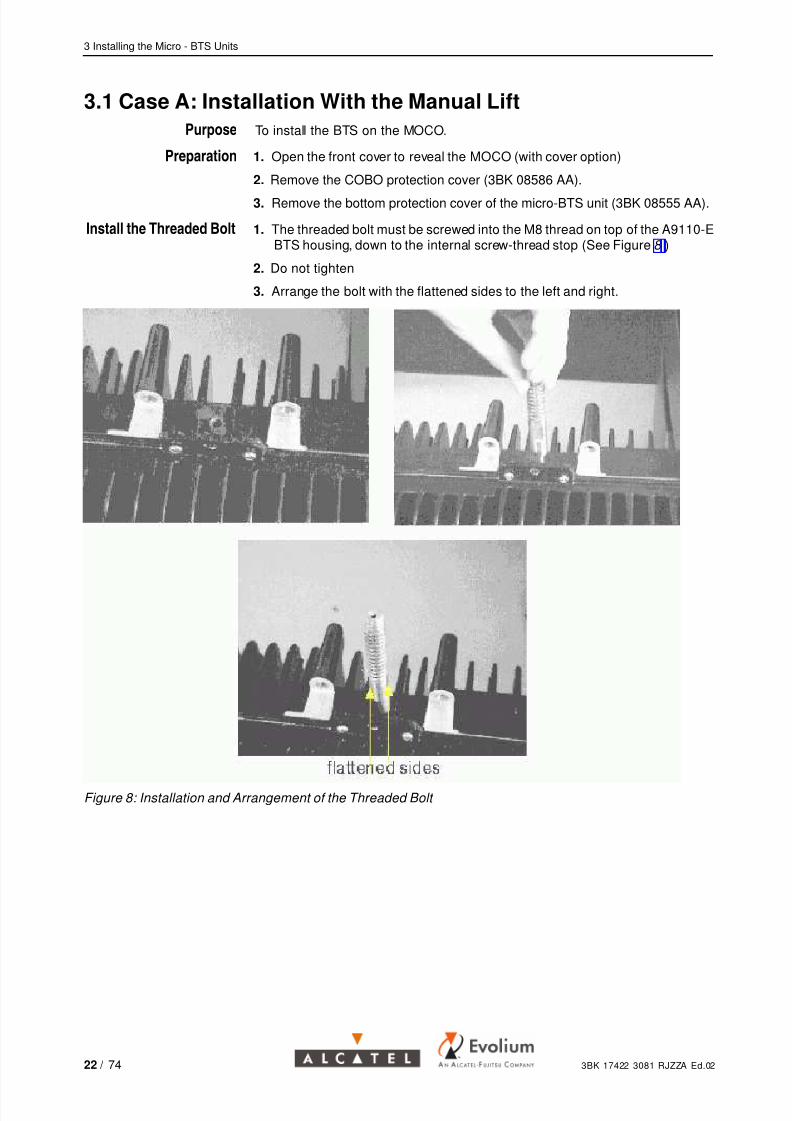
Install the Threaded Bolt 1. The threaded bolt must be screwed into the M8 thread on top of the A9110-EBTS housing, down to the internal screw-thread stop (See Figure 8 )
2. Do not tighten
3. Arrange the bolt with the flattened sides to the left and right.
Figure 8: Installation and Arrangement of the Threaded Bolt
22 / 74 3BK 17422 3081 RJZZA Ed.02
7/25/2019 A9110E UBTS Commissioning
http://slidepdf.com/reader/full/a9110e-ubts-commissioning 23/74
3 Installing the Micro - BTS Units
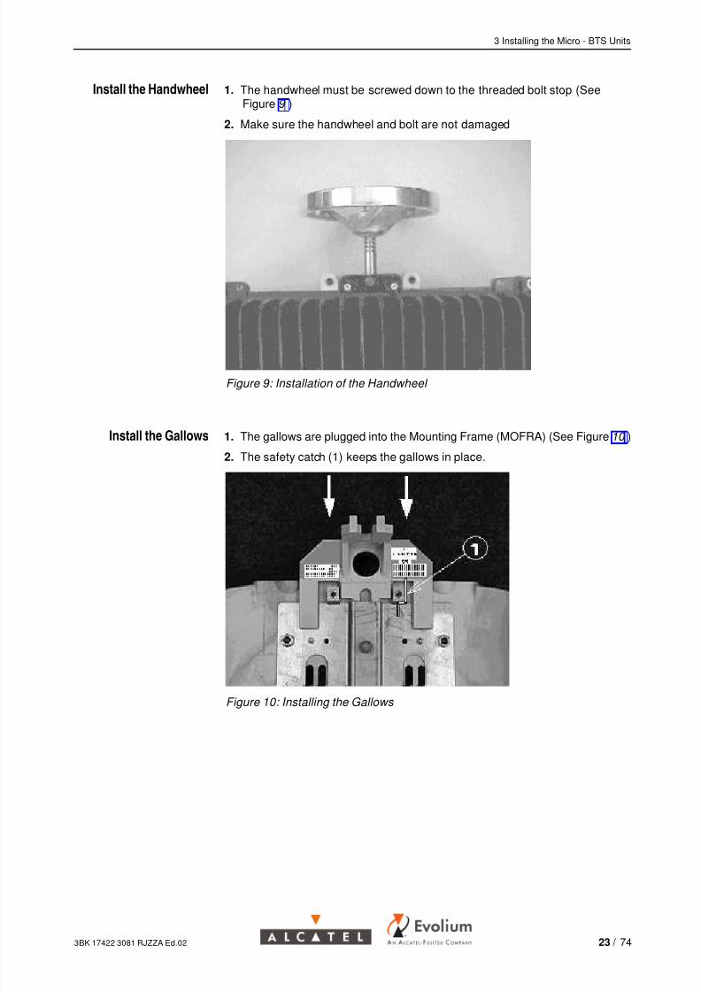
Install the Handwheel 1. The handwheel must be screwed down to the threaded bolt stop (SeeFigure 9 )
2. Make sure the handwheel and bolt are not damaged
Figure 9: Installation of the Handwheel
Install the Gallows 1. The gallows are plugged into the Mounting Frame (MOFRA) (See Figure 10 )
2. The safety catch (1) keeps the gallows in place.
Figure 10: Installing the Gallows
3BK 17422 3081 RJZZA Ed.02 23 / 74
7/25/2019 A9110E UBTS Commissioning
http://slidepdf.com/reader/full/a9110e-ubts-commissioning 24/74
3 Installing the Micro - BTS Units
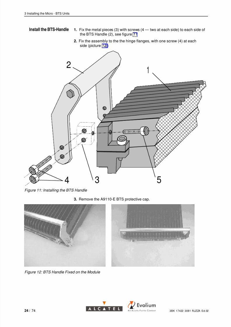
Install the BTS-Handle 1. Fix the metal pieces (3) with screws (4 — two at each side) to each side ofthe BTS Handle (2), see figure 11
2. Fix the assembly to the the hinge flanges, with one screw (4) at eachside (picture 12 )
1 2 3 4 5 6 7 8 9 0 1 2 3 4 5 6 7 8
1 2 3 4 5 6 7 8 9 0 1 2 3 4 5 6 7 8
1 2 3 4 5 6 7 8 9 0 1 2 3 4 5 6 7 8
1 2 3 4 5 6 7 8 9 0 1 2 3 4 5 6 7 8
1 2 3 4 5 6 7 8 9 0 1 2 3 4 5 6 7 8
1 2 3 4 5 6 7 8 9 0 1 2 3 4 5 6 7 8
1 2 3 4 5 6 7 8 9 0 1 2 3 4 5 6 7 8
1 2 3 4 5 6 7 8 9 0 1 2 3 4 5 6 7 8
1 2 3 4 5 6 7 8 9 0 1 2 3 4 5 6 7 8
1 2 3 4 5 6 7 8 9 0 1 2 3 4 5 6 7 8
1 2 3 4 5 6 7 8 9 0 1 2 3 4 5 6 7 8
1 2 3 4 5 6 7 8 9 0 1 2 3 4 5 6 7 8
1 2 3 4 5 6 7 8 9 0 1 2 3 4 5 6 7 8
1 2 3 4 5 6 7 8 9 0 1 2 3 4 5 6 7 8
1 2 3 4 5 6 7 8 9 0 1 2 3 4 5 6 7 8
1 2 3 4 5 6 7 8 9 0 1 2 3 4 5 6 7 8
1 2 3 4 5 6 7 8 9 0 1 2 3 4 5 6 7 8
1 2 3 4 5 6 7 8 9 0 1 2 3 4 5 6 7 8
1 2 3 4 5 6 7 8 9 0 1 2 3 4 5 6 7 8
1 2 3 4 5 6 7 8 9 0 1 2 3 4 5 6 7 8
1 2 3 4 5 6 7 8 9 0 1 2 3 4 5 6 7 8
1 2 3 4 5 6 7 8 9 0 1 2 3 4 5 6 7 8
1 2 3 4 5 6 7 8 9 0 1 2 3 4 5 6 7 8
1 2 3 4 5 6 7 8 9 0 1 2 3 4 5 6 7 8
1 2 3 4 5 6 7 8 9 0 1 2 3 4 5 6 7 8
1 2 3 4 5 6 7 8 9 0 1 2 3 4 5 6 7 8
1 2 3 4 5 6 7 8 9 0 1 2 3 4 5 6 7 8
12
34 5Figure 11: Installing the BTS Handle
3. Remove the A9110-E BTS protective cap.
Figure 12: BTS Handle Fixed on the Module
24 / 74 3BK 17422 3081 RJZZA Ed.02

7/25/2019 A9110E UBTS Commissioning
http://slidepdf.com/reader/full/a9110e-ubts-commissioning 25/74
3 Installing the Micro - BTS Units
Install the A9110-E BTS
in Position
1. Two people place the unit in the gallows (See Figure 13 )
2. The A9110-E BTS housing is let down by rotating the handwheel.
3. Ensure that the housing descends into the right position.
Figure 13: Putting the A9110-E BTS in Position
Fix the BTS in Position 1. Fix the housing on the mounting frame with the two screws on top ofhousing (See Figure 14 )
2. Fix the housing on COBO with the two screws left and right of COBO.
Figure 14: Fixing the Unit
Remove the Manual Lift
and the Handle
1. Completely unscrew the handwheel, then remove it
2. Remove the gallows from MOFRA, by lifting it (and pushing the safety catch)
3. Unscrew the threaded bolt and remove it from the housing
4. Detach the BTS-handle from the housing by releasing the screw (5) onfigure 11.
3BK 17422 3081 RJZZA Ed.02 25 / 74

7/25/2019 A9110E UBTS Commissioning
http://slidepdf.com/reader/full/a9110e-ubts-commissioning 26/74
3 Installing the Micro - BTS Units
3.2 Case B: Installation With the Crane
3.2.1 Specific Safety Instructions for Craning
You must carefully read the " A9110 Crane Instruction Manual " and theseinstructions before using the crane.
It is strictly prohibited to stand under a floating crane load during the
operation
Hot surface warning : Don’t handle the crane by its motor after use, the
temperature can exceed 45 degrees Celsius (see left, " Hot Surface "label on the crane)
Check availability of the completed " Security control - check list and report", enclosed with the crane (see " A9110 Crane Instruction Manual " ) the checkmust be carried out every six months, note the check date in the CCL.
3.2.2 Installation of the Crane on MOFRA
Procedure 1. Check that the lifting ring and the two screws for fixing to MOFRA areavailable
2. Mount the lifting ring onto the top part of the micro-BTS unit. The ring mustbe screwed completely (See Figure 15 )
3. Put the crane on top of MOFRA. The small safety blade keeps the cranein place (See Figure 16 )
4. Open the COBO door
5. Connect the crane power cable to the ACout BTS power connector (SeeFigure 17 )
6. Hook the cables as shown in the drawings.
Figure 15: Mounting the Lifting Ring
26 / 74 3BK 17422 3081 RJZZA Ed.02

7/25/2019 A9110E UBTS Commissioning
http://slidepdf.com/reader/full/a9110e-ubts-commissioning 27/74
3 Installing the Micro - BTS Units
MOFRA
Crane
Power cable
Figure 16: Installing the Crane
Ac out BTS connector is used to power the crane
3BK 17422 3081 RJZZA Ed.02 27 / 74

7/25/2019 A9110E UBTS Commissioning
http://slidepdf.com/reader/full/a9110e-ubts-commissioning 28/74
3 Installing the Micro - BTS Units
Figure 17: ACout BTS Power Connector of ACCO Board is Used to Power the Crane
3.2.3 Preparation for Craning
The following checks and precautions must be considered before craning!Depending of the country and customer regulations more tests foroverloading and usage time may be required.To be checked and applied!
Purpose
To check the fixing of the MOCO and crane.
Procedure 1. Check the screws securing the MOCO on the wall2. Define a safety area 2 m around the MOFRA and make sure that nobody will
enter the area during operations
3. Move the unit under the crane on the floor
4. Remove the COBO protection cover (3BK 08586 AA).
5. Close the circuit breakers that power COBO
6. Using the switching box on the crane power cable, let down the liftingband to the micro-BTS level
7. Hang the unit on the crane (make sure the belt is not turned on itself)
8. Lift the unit and suspend it 10 cm above the floor9. Execute a movement up and down with the micro-BTS
10. Lay the micro-BTS an the floor
11. Check the MOFRA - Crane assembly and fixings.
28 / 74 3BK 17422 3081 RJZZA Ed.02
7/25/2019 A9110E UBTS Commissioning
http://slidepdf.com/reader/full/a9110e-ubts-commissioning 29/74
3 Installing the Micro - BTS Units
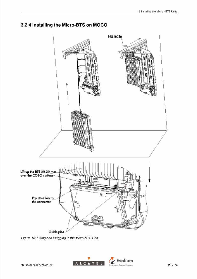
3.2.4 Installing the Micro-BTS on MOCO
Figure 18: Lifting and Plugging in the Micro-BTS Unit
3BK 17422 3081 RJZZA Ed.02 29 / 74

7/25/2019 A9110E UBTS Commissioning
http://slidepdf.com/reader/full/a9110e-ubts-commissioning 30/74
3 Installing the Micro - BTS Units
Take care not to damage the connectors during the operation.Do not lift the BTS by hand from the ground, use the crane!
Do not work under powerOpen the circuit breakers to be sure that the power supply isdisconnected.For installation with SSC: Check that the “ Battery back-up “ is OFF(red LED is lit) !!!
Purpose
To install the BTS on the MOCO.
Procedure 1. Lift the micro-BTS unit to an appropriate level for mounting (See Figure 18 )
2. Remove the bottom protection cover of the micro-BTS unit (3BK 08555 AA).3. Fit the handle on the reel of the crane, on the left side
4. Move the micro-BTS nearer to the MOFRA (by pushing the handle) and fit itonto the guide bolts (there are two guide bolts on MOFRA that must fit intothe back part of the micro-BTS unit)
5. Plug the micro-BTS unit into the COBO by slowly releasing the unit andfitting the two guide pins of the COBO into the corresponding holes in themicro-BTS housing
6. Fix the micro-BTS onto the MOCO using the four screws provided (SeeFigure 19 )
7. Unhook the micro-BTS8. Unplug the crane power cable
9. Remove the crane from MOFRA
10. Unscrew the lifting ring and put it with the crane to avoid losing it.
30 / 74 3BK 17422 3081 RJZZA Ed.02

7/25/2019 A9110E UBTS Commissioning
http://slidepdf.com/reader/full/a9110e-ubts-commissioning 31/74
3 Installing the Micro - BTS Units
Figure 19: Fixing the Micro-BTS to MOCO
3BK 17422 3081 RJZZA Ed.02 31 / 74

7/25/2019 A9110E UBTS Commissioning
http://slidepdf.com/reader/full/a9110e-ubts-commissioning 32/74
3 Installing the Micro - BTS Units
32 / 74 3BK 17422 3081 RJZZA Ed.02
7/25/2019 A9110E UBTS Commissioning
http://slidepdf.com/reader/full/a9110e-ubts-commissioning 33/74
4 Making the Connections to the BTS
4 Making the Connections to the BTS
This chapter describes:
How to install the integrated antenna, with the integrated antenna option
How to instal the VSWR detector, with the VSWR option
How to make the necessary connections to the BTS units
3BK 17422 3081 RJZZA Ed.02 33 / 74

7/25/2019 A9110E UBTS Commissioning
http://slidepdf.com/reader/full/a9110e-ubts-commissioning 34/74
4 Making the Connections to the BTS
4.1 OPTION: Installing the Integrated Antenna
Purpose
To install the integrated antenna on each micro-BTS unit (master and slaves).
This procedure is the same for master and slave units.
Figure 20: Installation of Integrated Antenna (GSM and DCS)
Connect the integrated antenna to the upper housing side of the A9110-EBTS using the four self tapping screws (M3 x 16) provided in the integratedantenna kit.
The above figure also shows the special front cover and the final view of a
BTS with integrated antenna.On fact, the front cover will not be mounted until the end of commissioning.
34 / 74 3BK 17422 3081 RJZZA Ed.02

7/25/2019 A9110E UBTS Commissioning
http://slidepdf.com/reader/full/a9110e-ubts-commissioning 35/74
4 Making the Connections to the BTS
4.2 OPTION: Installing the VSWR Detector
Purpose To install the VSWR detector on each micro-BTS unit (master and slaves)
This procedure is the same for master and slave units.
4.2.1 Mechanics
Figure 21: The VSWR Detector
3BK 17422 3081 RJZZA Ed.02 35 / 74

7/25/2019 A9110E UBTS Commissioning
http://slidepdf.com/reader/full/a9110e-ubts-commissioning 36/74
4 Making the Connections to the BTS
4.2.2 Fixing the VSWR Detector
The VSWR detector can not be used together with an integrated antenna, if theisolation between antennas on the same site is < 25 dB.
Procedure 1. Unlock the bottom section of the front protective cover, open it upwards andfix it at the front cover by the installed magnetic snap-on fastening
2. Connect the VSWR detector to the antenna output connector of the A9110-Eby screwing the N male connector (See Figure 22 )
3. Connect the VSWR RF jumper cable to the RF output N-female connector ofthe VSWR detector
4. Connect the standard antenna cable to the RF jumper cable.
EvoliumBTS A9110−E
VSWR
detector
RF Jumper Cable
Antenna Jumper
COBO
F
M : N−male connector F : N− female connector
M F M
Figure 22: VSWR Detector - RF Installation
36 / 74 3BK 17422 3081 RJZZA Ed.02

7/25/2019 A9110E UBTS Commissioning
http://slidepdf.com/reader/full/a9110e-ubts-commissioning 37/74
4 Making the Connections to the BTS
4.2.3 Connecting the Cables
Procedure 1. Open the COBO
2. Unscrew the appropriate PG gland
3. Run the ALARM / VCC cable through that PG gland into COBO
4. Screw the PG gland with the ALARM/ VCC cable
5. Connect the ALARM/ VCC wires inside the COBO to the clamp stripslocated on the ABISCO board as shown in Figure 23 .
In a two antenna configuration the isolated wires for VCC-VSWR1 andVCC-VSWR2 and ground (GND) have to be fixed together with the enclosedcable and sleeves and inserted in the described terminals of the ABISCO(See Figure 23 ).
Figure 23: Connecting the ALARM / VCC Cables
3BK 17422 3081 RJZZA Ed.02 37 / 74

7/25/2019 A9110E UBTS Commissioning
http://slidepdf.com/reader/full/a9110e-ubts-commissioning 38/74
4 Making the Connections to the BTS
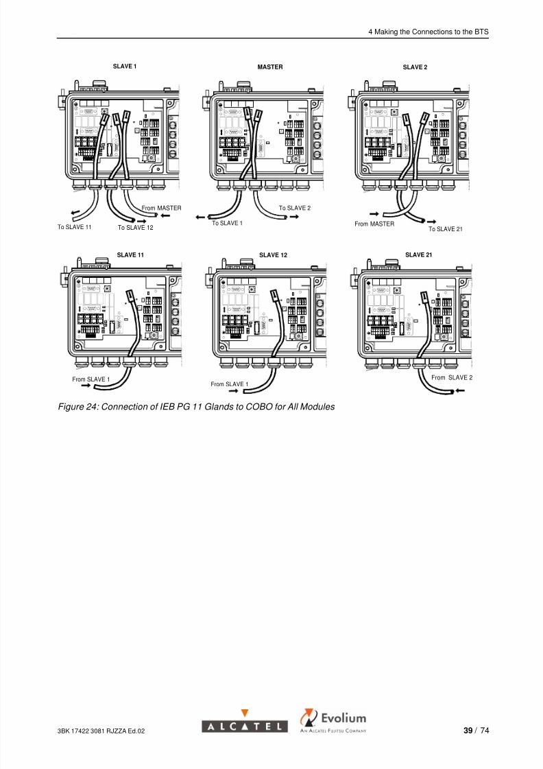
4.3 Making the Connections to the BTS
One lower slave cannot be equipped because of 12 TRX limitation!Depending on site configuration, you can have maximum 3 lower slave unitson the 4 possible positions: Slave11, Slave12, Slave 21, Slave 22.
When connecting a slave unit, the position where to plug the IEB cable intomaster unit (S1 or S2 connectors) will determine if it is Slave1 or Slave2.
Purpose
To connect the antenna
To connect the IEB cables in a master-slave configuration.
Procedure 1. With the integrated antenna option, connect the integrated antennas RFcables to the antenna connector(s) of the micro-BTS unit (master andslaves, as appropriate)
2. With external antennas, connect the antenna jumper(s) to the antennaconnector(s) of the micro-BTS units (master and slaves) according to theirsector number (See Information Required (Section 1.8) )
3. To install the slave units, connect the IEB cables between the master andslaves:
At the Master unit plug the cable into the“ Conn. to Slave 1 “ or
“ Conn. to Slave 2 “ connector, depending the slave (1 or 2) that is
going to be connected
At the Slave 1 unit plug the cable from master into the “ Conn. to
Master “ connector. Plug the cable to Slave 11 into “ Conn. to Slave 1
“ and / or the cable to Slave 12 into “ Conn. to Slave 2“.
At the Slave 2 unit plug the cable from master into the “ Conn. to
Master “ connector. Plug the cable to Slave 21 into “ Conn. to Slave 1
“ and / or the cable to Slave 22 into “ Conn. to Slave 2“.
At the Slave 11 unit and / or Slave 12 unit plug the cables from Slave1
into the “ Conn. to Master “ connector.
At the Slave 21 unit and / or Slave 22 unit plug the cable from Slave2
into the “ Conn. to Master “ connector.
38 / 74 3BK 17422 3081 RJZZA Ed.02
7/25/2019 A9110E UBTS Commissioning
http://slidepdf.com/reader/full/a9110e-ubts-commissioning 39/74
4 Making the Connections to the BTS
To SLAVE 2
MASTER
To SLAVE 1
From MASTER
SLAVE 1
To SLAVE 11 To SLAVE 12From MASTER
SLAVE 2
To SLAVE 21
SLAVE 12
From SLAVE 1From SLAVE 1
SLAVE 11 SLAVE 21
From SLAVE 2
Figure 24: Connection of IEB PG 11 Glands to COBO for All Modules
3BK 17422 3081 RJZZA Ed.02 39 / 74
7/25/2019 A9110E UBTS Commissioning
http://slidepdf.com/reader/full/a9110e-ubts-commissioning 40/74
7/25/2019 A9110E UBTS Commissioning
http://slidepdf.com/reader/full/a9110e-ubts-commissioning 41/74
5 Checking Power Supply and Powering Up
5 Checking Power Supply and Powering Up
This chapter describes how to check the power supply voltage and power upthe micro-BTS units (master and slaves).
Before checking the power supply and powering up the micro-BTS, ensurethat the safety instructions in the SAF procedure are followed ( See BSS Methods Handbook ). It is essential that:
The protective earth is connected to the equipment earth terminal
The ACout BTS connectors in the COBOs (Figure 25 ) that feed the
micro-BTS units are disconnected.
3BK 17422 3081 RJZZA Ed.02 41 / 74
7/25/2019 A9110E UBTS Commissioning
http://slidepdf.com/reader/full/a9110e-ubts-commissioning 42/74
5 Checking Power Supply and Powering Up
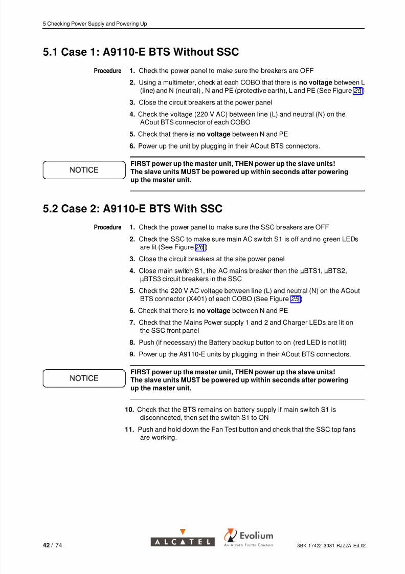
5.1 Case 1: A9110-E BTS Without SSC
Procedure 1. Check the power panel to make sure the breakers are OFF
2. Using a multimeter, check at each COBO that there is no voltage between L(line) and N (neutral) , N and PE (protective earth), L and PE (See Figure 25 )
3. Close the circuit breakers at the power panel
4. Check the voltage (220 V AC) between line (L) and neutral (N) on theACout BTS connector of each COBO
5. Check that there is no voltage between N and PE
6. Power up the unit by plugging in their ACout BTS connectors.
FIRST power up the master unit, THEN power up the slave units!The slave units MUST be powered up within seconds after poweringup the master unit.
5.2 Case 2: A9110-E BTS With SSC
Procedure 1. Check the power panel to make sure the SSC breakers are OFF
2. Check the SSC to make sure main AC switch S1 is off and no green LEDsare lit (See Figure 26 )
3. Close the circuit breakers at the site power panel
4. Close main switch S1, the AC mains breaker then the µBTS1, µBTS2,µBTS3 circuit breakers in the SSC
5. Check the 220 V AC voltage between line (L) and neutral (N) on the ACout
BTS connector (X401) of each COBO (See Figure 25 )
6. Check that there is no voltage between N and PE
7. Check that the Mains Power supply 1 and 2 and Charger LEDs are lit onthe SSC front panel
8. Push (if necessary) the Battery backup button to on (red LED is not lit)
9. Power up the A9110-E units by plugging in their ACout BTS connectors.
FIRST power up the master unit, THEN power up the slave units!The slave units MUST be powered up within seconds after poweringup the master unit.
10. Check that the BTS remains on battery supply if main switch S1 isdisconnected, then set the switch S1 to ON
11. Push and hold down the Fan Test button and check that the SSC top fansare working.
42 / 74 3BK 17422 3081 RJZZA Ed.02

7/25/2019 A9110E UBTS Commissioning
http://slidepdf.com/reader/full/a9110e-ubts-commissioning 43/74
5 Checking Power Supply and Powering Up
If the BTS must be powered down, disconnect the batteries first by pushingthe “ Back-up Off “ switch to ON (red LED is lit), then set the main powerswitch S1 to OFF.
BTS fuses
(T=2.5 A)
FAN fuses
(T=2.5 A)L
N
L
N
SLAVE 1SLAVE 2
X403X404
X401
X402
X400
ACoutBTS
IEC− Conn.
FAN
ACin, Mains
L
L
LL
N
NN
N
PE
PE PE
PE
Figure 25: ACCO Board
PS1 PS2 PS3
Battery unit
AC Connection Area
S1
Battery back−Up button
Back−UpOff
Power 230V ACSocket AC230V AC mains
µBTS1
µBTS2
µBTS3
Fan Test
Power Supply 1
Power Supply 2
Charger
Mains
Figure 26: SSC Switch Configuration
3BK 17422 3081 RJZZA Ed.02 43 / 74

7/25/2019 A9110E UBTS Commissioning
http://slidepdf.com/reader/full/a9110e-ubts-commissioning 44/74
5 Checking Power Supply and Powering Up
44 / 74 3BK 17422 3081 RJZZA Ed.02

7/25/2019 A9110E UBTS Commissioning
http://slidepdf.com/reader/full/a9110e-ubts-commissioning 45/74
6 Commissioning Tests
6 Commissioning Tests
This chapter describes the following operations:
BTS software downloading
Setting antenna mapping
BTS initialization
Performing BTS inventory
Setting and checking the external alarms
Checking status of modules
Checking the antenna VSWR
Abis loop test
End of commissioning.
Use the antistatic wrist strap when working with the ABISCO board.Check that the BTS is isolated :At the DDF side by disconnecting terminals, from the PCM link comingfrom the network.For installation with SSC, by disconnecting connectors X2, X3 and X4on the connection area.
One lower slave cannot be equipped because of 12 TRX limitation!Depending on site configuration, you can have maximum 3 lower slave unitson the 4 possible positions: Slave11, Slave12, Slave 21, Slave 22.Configuration is determined by IEB cable connections between units
3BK 17422 3081 RJZZA Ed.02 45 / 74
7/25/2019 A9110E UBTS Commissioning
http://slidepdf.com/reader/full/a9110e-ubts-commissioning 46/74
6 Commissioning Tests
6.1 BTS Software Downloading
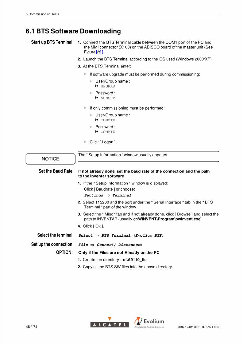
Start up BTS Terminal 1. Connect the BTS Terminal cable between the COM1 port of the PC andthe MMI connector (X100) on the ABISCO board of the master unit (SeeFigure 28 )
2. Launch the BTS Terminal according to the OS used (Windows 2000/XP)3. At the BTS Terminal enter:
If software upgrade must be performed during commissioning:
User/Group name :UPGRAD
Password :
SUMSUP
If only commissioning must be performed:
User/Group name :
COMMTE
Password :
COMMTE
Click [ Logon ].
The “ Setup Information “ window usually appears.
Set the Baud Rate If not already done, set the baud rate of the connection and the pathto the Inventar software
1. If the “ Setup Information “ window is displayed:
Click [ Baudrate ] or choose:
Settings ⇒ Terminal
2. Select 115200 and the port under the “ Serial Interface “ tab in the “ BTSTerminal “ part of the window
3. Select the “ Misc “ tab and if not already done, click [ Browse ] and select thepath to INVENTAR (usually c:\WINVENT\Program\pwinvent.exe)
4. Click [ Ok ].
Select the terminal Select ⇒ BTS Terminal (Evolium BTS)
Set up the connection File ⇒ Connect/ Disconnect
OPTION: Only if the Files are not Already on the PC
1. Create the directory : c:\A9110_fls
2. Copy all the BTS SW files into the above directory.
46 / 74 3BK 17422 3081 RJZZA Ed.02
7/25/2019 A9110E UBTS Commissioning
http://slidepdf.com/reader/full/a9110e-ubts-commissioning 47/74
6 Commissioning Tests
Download the BTS With
the BTS TE
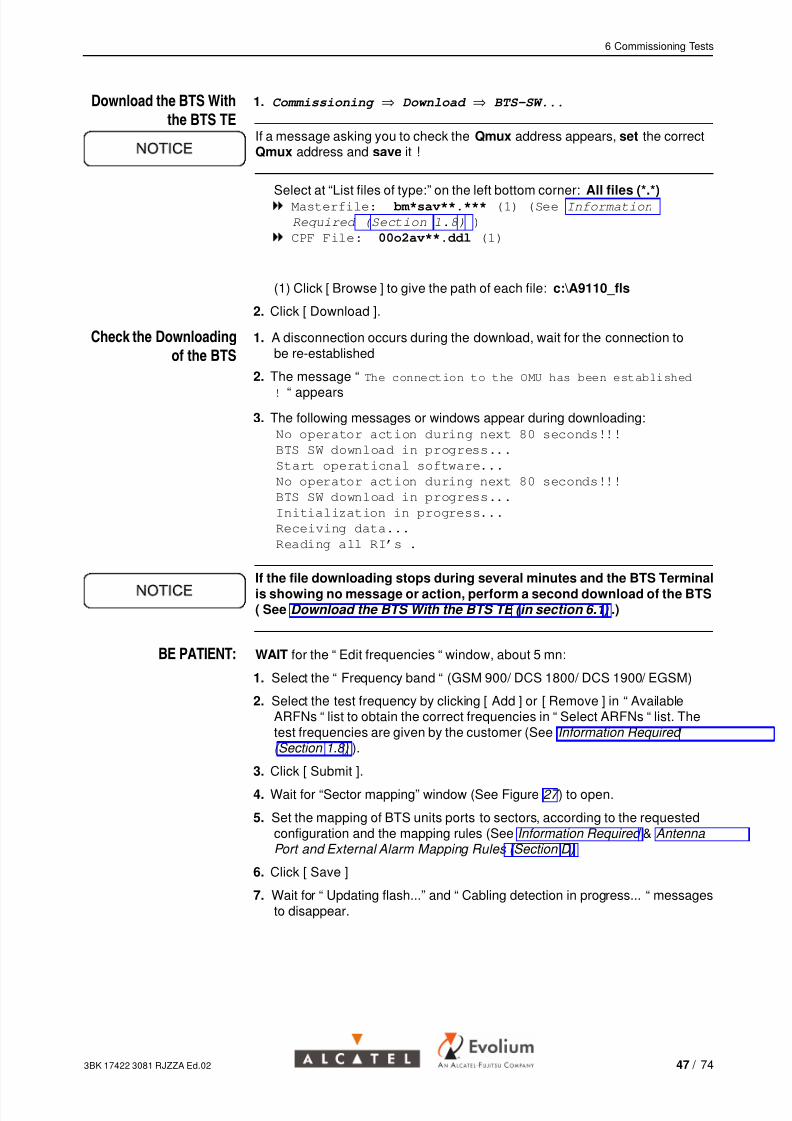
1. Commissioning ⇒ Download ⇒ BTS-SW...
If a message asking you to check the Qmux address appears, set the correctQmux address and save it !
Select at “List files of type:” on the left bottom corner: All files (*.*)Masterfile: bm*sav**.*** (1) (See Information
Required (Section 1.8) )
CPF File: 00o2av**.ddl (1)
(1) Click [ Browse ] to give the path of each file: c:\A9110_fls
2. Click [ Download ].
Check the Downloading
of the BTS
1. A disconnection occurs during the download, wait for the connection tobe re-established
2. The message “ The connection to the OMU has been established
! “ appears
3. The following messages or windows appear during downloading:
No operator action during next 80 seconds!!!
BTS SW download in progress...
Start operational software...
No operator action during next 80 seconds!!!
BTS SW download in progress...
Initialization in progress...
Receiving data...
Reading all RI’s .
If the file downloading stops during several minutes and the BTS Terminalis showing no message or action, perform a second download of the BTS( See Download the BTS With the BTS TE ( in section 6.1 ) .)
BE PATIENT: WAIT for the “ Edit frequencies “ window, about 5 mn:
1. Select the “ Frequency band “ (GSM 900/ DCS 1800/ DCS 1900/ EGSM)
2. Select the test frequency by clicking [ Add ] or [ Remove ] in “ AvailableARFNs “ list to obtain the correct frequencies in “ Select ARFNs “ list. Thetest frequencies are given by the customer (See Information Required ( Section 1.8) ).
3. Click [ Submit ].
4. Wait for “Sector mapping” window (See Figure 27 ) to open.
5. Set the mapping of BTS units ports to sectors, according to the requestedconfiguration and the mapping rules (See Information Required & Antenna Port and External Alarm Mapping Rules (Section D)
6. Click [ Save ]
7. Wait for “ Updating flash...” and “ Cabling detection in progress... “ messagesto disappear.
3BK 17422 3081 RJZZA Ed.02 47 / 74

7/25/2019 A9110E UBTS Commissioning
http://slidepdf.com/reader/full/a9110e-ubts-commissioning 48/74
6 Commissioning Tests
Figure 27: “ Sector Mapping Micro BTS“ Window
6.2 BTS Initialization
Initialize Commissioning 1. At BTS Terminal select:
Commissioning ⇒ Initialization ⇒ All sectors...
2. Wait for the “Initialization for commissioning in progress“message to disappear
3. The “ HW check configuration “ window appears4. Check that the configuration shown in the “ HW check configuration “
window corresponds to the requested HW configuration (See Information Required (Section 1.8) )
5. Wait for the MTRE and ANX module downloading to finish.
Workaround: If the “ HW check configuration “ window information does not correspondto the antenna mapping information written in RI (this behaviour appearsusually when the final antenna mapping information is different from the initialinformation), repeat the initialization of all sectors (steps 1 and 2).
48 / 74 3BK 17422 3081 RJZZA Ed.02
7/25/2019 A9110E UBTS Commissioning
http://slidepdf.com/reader/full/a9110e-ubts-commissioning 49/74
6 Commissioning Tests
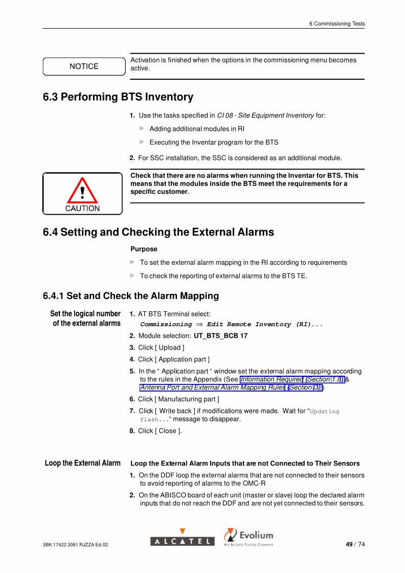
Activation is finished when the options in the commissioning menu becomesactive.
6.3 Performing BTS Inventory1. Use the tasks specified in CI 08 - Site Equipment Inventory for:
Adding additional modules in RI
Executing the Inventar program for the BTS
2. For SSC installation, the SSC is considered as an additional module.
Check that there are no alarms when running the Inventar for BTS. Thismeans that the modules inside the BTS meet the requirements for aspecific customer.
6.4 Setting and Checking the External Alarms
Purpose
To set the external alarm mapping in the RI according to requirements
To check the reporting of external alarms to the BTS TE.
6.4.1 Set and Check the Alarm MappingSet the logical numberof the external alarms
1. AT BTS Terminal select:
Commissioning ⇒ Edit Remote Inventory (RI)...
2. Module selection: UT_BTS_BCB 17
3. Click [ Upload ]
4. Click [ Application part ]
5. In the “ Application part “ window set the external alarm mapping accordingto the rules in the Appendix (See Information Required (Section 1.8) &Antenna Port and External Alarm Mapping Rules (Section D) )
6. Click [ Manufacturing part ]
7. Click [ Write back ] if modifications were made. Wait for “Updating
flash...“ message to disappear.
8. Click [ Close ].
Loop the External Alarm Loop the External Alarm Inputs that are not Connected to Their Sensors
1. On the DDF loop the external alarms that are not connected to their sensorsto avoid reporting of alarms to the OMC-R
2. On the ABISCO board of each unit (master or slave) loop the declared alarminputs that do not reach the DDF and are not yet connected to their sensors.
3BK 17422 3081 RJZZA Ed.02 49 / 74

7/25/2019 A9110E UBTS Commissioning
http://slidepdf.com/reader/full/a9110e-ubts-commissioning 50/74
6 Commissioning Tests
6.4.2 Test the External Alarms
Check the Alarms 1. On the BTS Terminal display the external alarms
2. Monitor ⇒ Active Alarms
3. On the BTS Terminal check that there are no external alarms.
Check the Alarms in DDF If the external alarms are transferred to a terminal block, generate analarm and check its appearance on BTS Terminal
1. Open the circuits corresponding to the external alarms on the DDF side, byinserting a red disconnecting pin into the terminal block
2. On the BTS Terminal, check that the appropriate alarm message isgenerated
3. Close the circuit that has been opened at the terminal block by removing thedisconnecting pin
4. On the BTS Terminal, check that the external alarm message hasdisappeared.
Check the Alarms That
Do Not Reach the DDF
In COBO (master and slaves)
1. For the declared external alarms that do not reach the DDF, generate analarm by opening and then closing a loop (See Connectors Description ( in section C ) in appendix for connectors description)
2. Check alarm reporting on the BTS Terminal.
Note: If the Fan option was included, check the fan alarm:
1. Disconnect the fan power supply cable from ACCO board
2. On the BTS Terminal , check that the alarm is present:
’ BTS1, BTS EXTERN, Air condition (1) ’
3. Plug in the fan power supply cable and check that the alarm is cleared.
Note: If the SSC option was included, check the external alarms:
1. Set the mains switch S1 to OFF to check mains power failure
2. On the BTS Terminal, check that alarm 2 is present, then set switch S1to ON again
3. On the BTS Terminal, check that alarm 3 is present (SSC door open) bycompletely closing (with the key) and opening the door.
Note: If the VSWR option was included, check the external alarms:
1. Make the connections as follows:For A9110-E BTS units with one antenna output:
• use ANT A and the following MTREs for transmission:
UT_TRE 18 or UT_TRE 19 for master
UT_TRE 38 or UT_TRE 39 for slave 1
UT_TRE 54 or UT_TRE 55 for slave 2.
UT_TRE 42 or UT_TRE 43 for slave 11.
UT_TRE 46 or UT_TRE 47 for slave 12.
UT_TRE 58 or UT_TRE 59 for slave 21.
UT_TRE 62 or UT_TRE 63 for slave 22.
50 / 74 3BK 17422 3081 RJZZA Ed.02

7/25/2019 A9110E UBTS Commissioning
http://slidepdf.com/reader/full/a9110e-ubts-commissioning 51/74
6 Commissioning Tests
For A9110-E BTS units with two antenna outputs
• use ANT A and the following MTREs for transmission:
UT_TRE 19 for master
UT_TRE 39 for slave 1
UT_TRE 55 for slave 2.UT_TRE 43 for slave 11.
UT_TRE 47 for slave 12.
UT_TRE 59 for slave 21.
UT_TRE 63 for slave 22.
• use ANT B and the following MTREs for transmission:
UT_TRE 18 for master
UT_TRE 38 for slave 1
UT_TRE 54 for slave 2.
UT_TRE 42 for slave 11.
UT_TRE 46 for slave 12.
UT_TRE 58 for slave 21.
UT_TRE 62 for slave 22.
2. Check if an alarm is present at BTS Terminal:
Commissioning ⇒ Output Power Test
In the “ Output Power Test “ window select the MTRE Number:
UT_TRE** (See above)
Select one timeslot and click [ On ] to enable the power
Select an attenuation of -10dB on the used timeslot
Click [ Start ]
Wait for the BTS to start the emission
Disconnect the antenna cable from the RF jumper cable.
As the power level is lower than 50mW you are allowed to disconnect the cable..
Wait 15 seconds to see if an alarm is sent to the BTS Terminal.
At the BTS Terminal choose: Monitor ⇒ Active alarms
Check that an Alarm related to the tested TRE is present
Connect the antenna cable to the RF jumper cable
Check at the BTS Terminal that no alarms are present
3BK 17422 3081 RJZZA Ed.02 51 / 74
7/25/2019 A9110E UBTS Commissioning
http://slidepdf.com/reader/full/a9110e-ubts-commissioning 52/74
6 Commissioning Tests
Click [ Stop ]
Wait for MTRE to stop transmission.
After pressing the [ Stop ] button wait until MTRE stops transmission.Follow the messages that appear in the bottom part of the window,
which indicates the state of MTRE.
3. Repeat the actions from step 2 for all the antenna outputs of all BTSunits (master and slaves).
6.5 Checking the Status of Modules
Check the Status of
the BTS
1. At BTS Terminal choose:
Monitor ⇒ BTS Modules
2. Check that BTS, CLLK, OMU and EACB are IT
3. Check that the MTREs and TR_CLK are OP.
Check the Active Alarms 1. At BTS Terminal choose:
Monitor ⇒ Active Alarms
2. Check that there are no alarms present.
6.6 VSWR Check
Purpose
To connect the BTS to the antenna
To check the Voltage Standing Wave Ration (VSWR) of the transmit antenna.
Before transmitting on the antenna:
Check that transmission is allowed at the nominal frequency
If there are no antennas, measure the VSWR across the load.
The VSWR measurement must be performed for each antenna output!
Connect the Power
Meter/ Reflectometer
Connect the power meter/ reflectometer between the BTS antenna jumperand antenna or load as appropiate
1. For A9110-E BTS units with one antenna output:
• connect the power meter/ reflectometer to the antenna jumper connectedto ANT A and use the following MTREs for transmission:
UT_TRE 18 or UT_TRE 19 for master
UT_TRE 38 or UT_TRE 39 for slave 1
UT_TRE 54 or UT_TRE 55 for slave 2.
UT_TRE 42 or UT_TRE 43 for slave 11.
52 / 74 3BK 17422 3081 RJZZA Ed.02
7/25/2019 A9110E UBTS Commissioning
http://slidepdf.com/reader/full/a9110e-ubts-commissioning 53/74
6 Commissioning Tests
UT_TRE 46 or UT_TRE 47 for slave 12.
UT_TRE 58 or UT_TRE 59 for slave 21.
UT_TRE 62 or UT_TRE 63 for slave 22.
2. For A9110-E BTS units with two antenna outputs
• connect the power meter/ reflectometer to the antenna jumper connectedto ANT A and use the following MTREs for transmission:
UT_TRE 19 for master
UT_TRE 39 for slave 1
UT_TRE 55 for slave 2.
UT_TRE 43 for slave 11.
UT_TRE 47 for slave 12.
UT_TRE 59 for slave 21.
UT_TRE 63 for slave 22.
• connect the power meter/ reflectometer to the antenna jumper connectedto ANT B and use the following MTREs for transmission:
UT_TRE 18 for master
UT_TRE 38 for slave 1
UT_TRE 54 for slave 2.
UT_TRE 42 for slave 11.
UT_TRE 46 for slave 12.UT_TRE 58 for slave 21.
UT_TRE 62 for slave 22.
Measure the VSWR Measure the VSWR of the antenna (VSWR1) or across the load (VSWR2) ifthere is no antenna
Measure the VSWR ofthe antenna (VSWR1) 1. At BTS Termial choose:
Commissioning ⇒ Output Power Test
2. In the “ Output Power Test “ window select the MTRE Number: UT_TRE**
(See above)
3. All Timeslots: click [ On ] to enable the power
4. Select an attenuation of -4dB on each timeslot from TS0 to TS7
5. Click [ Start ]
6. Record the VSWR value (VSWRx):
VSWR 1 when measuring with antenna connected
VSWR 2 when measuring across the load.
7. Click [ Stop ]
8. Wait for MTRE to stop transmission.
3BK 17422 3081 RJZZA Ed.02 53 / 74
7/25/2019 A9110E UBTS Commissioning
http://slidepdf.com/reader/full/a9110e-ubts-commissioning 54/74
6 Commissioning Tests
Do not disconnect the power meter, the antenna or the load during MTREtransmission. After pressing the [ Stop ] button wait until MTRE stopstransmission.Follow the messages that appear in the bottom part of the window,which indicates the state of MTRE.
Measure the VSWR
(VSWR 2) Using a Load
If antenna VSWR 1 > 1.3 measure the VSWR (VSWR 2) using a load
1. Instead of antennas use 50 ohm loads
2. Measure the VSWR 2 values with the BTS TE in the same way as inMeasure the VSWR of the antenna (VSWR1)
3. Analyze the results: (See Table 1 )
VSWR 1 is the VSWR value measured in Measure the VSWR of
the antenna (VSWR1)
VSWR 2 is the VSWR value measured in Measure the VSWR (VSWR
2) Using a Load.
Value Sanction Action
VSWR 2 >1.2 Fault in equipment supplied byAlcatel
Check the tightness of theconnectors
VSWR 2 ≤1.2 and
VSWR 1 ≤1.5
Fault on the feeder or antenna(when present)
Inform the operator that theVSWR is within a critical range
VSWR 2 ≤1.2 and
VSWR 1 >1.5
Fault on the antenna or feeder
(when present)
Report the high reading to the
Site Manager
Table 1: Interpretation of VSWR Results
Finish the Measurement 1. Disconnect the power meter and reconnect the antenna jumper tothe antenna or load as the case
2. Repeat steps 1 to 4 for all the antenna outputs of all the BTS units(master and slaves)
54 / 74 3BK 17422 3081 RJZZA Ed.02

7/25/2019 A9110E UBTS Commissioning
http://slidepdf.com/reader/full/a9110e-ubts-commissioning 55/74
6 Commissioning Tests
6.7 Abis Loop Test
Purpose To test the PCM cabling between the master unit and DDF.
For Microwave or TNL installation in SSC for PCM connection, do not performAbis loop test.
Procedure 1. At BTS Terminal choose:
Commissioning ⇒ Station Unit Test...
The “ Station Unit Test “ window appears.
In the “ Station Unit Test “ window, select “ external loop“
Click [ Start ].
A message appears prompting you to fit the shortcut connector.Do not use any shortcut connector, because you are testing the cabling tothe DDF, not the ABISCO board.
2. At the DDF (not on ABISCO) set up loops between TX and RX for Abis1and Abis2, using wires.
It is important for both Abis links to be looped!
3. At BTS Terminal:
Click [ Ok ]
Remove the loops when the respective message window appears and
then click [ Ok ]
Wait for the test to finish
Check that the list of tests shown in the “ Station Unit Test “ window is Ok
Click [ Cancel ].
6.8 End of Commissioning
Purpose
To update the Remote Inventory of all the modules according to the site
To perform an inventar in case any modules were changed during
commissioning
To end the commissioning phase
To save the commissioning report.
Procedure 1. At BTS Terminal :Commissioning ⇒ End
commissioning
3BK 17422 3081 RJZZA Ed.02 55 / 74
7/25/2019 A9110E UBTS Commissioning
http://slidepdf.com/reader/full/a9110e-ubts-commissioning 56/74
6 Commissioning Tests
2. Check that the commissioning date is correct:
If not, click [ Close ] and click [ Cancel ]
Modify the internal date of the PC (in Control Panel)
Go back to step 1.
3. Give the name of the BTS site (< 10 characters) and the NetworkIdentity.
4. Select all the modules from the list on the left (if any) to enter them inthe “ modules to be updated “ list
Click [ Add ] for all the modules on the left (if any)
Click [ Submit ].
The following message appears: ”Do you want to execute INVENTAR
now?”
5. Option: If any modules were added or changed during commissioning,run Inventar:
Click [ Yes ]
The “ Receiving Remote Inventory Data “ message appears, and the
INVENTAR application is launched
Use the tasks specified in CI 08 - Site Equipment Inventory for the
following actions:
Adding additional modules in RI (if appropiate)
Running Inventar for the BTS.
6. Option: If no modules were added or changed during commissioningclick [ No ]
When you end commissioning, the BTS is automatically reset after about 2minutes (the connection is lost for about 5s).Wait until the connection with the BTS is reestablished.The BTS is then ready for downloading from the BSC.
7. Save the “ Commissioning Report “ window:
Click [ Commissioning Report ] window to make it active
File ⇒ Save As...
Give a name to the file (Site name and number of BTS - no more then 8
characters) and save the file to a floppy disk.
56 / 74 3BK 17422 3081 RJZZA Ed.02

7/25/2019 A9110E UBTS Commissioning
http://slidepdf.com/reader/full/a9110e-ubts-commissioning 57/74
7 Setting Transmission Module Parameters
7 Setting Transmission Module Parameters
This chapter describes how to configure the transmission module of the SUMboard.
3BK 17422 3081 RJZZA Ed.02 57 / 74
7/25/2019 A9110E UBTS Commissioning
http://slidepdf.com/reader/full/a9110e-ubts-commissioning 58/74
7 Setting Transmission Module Parameters
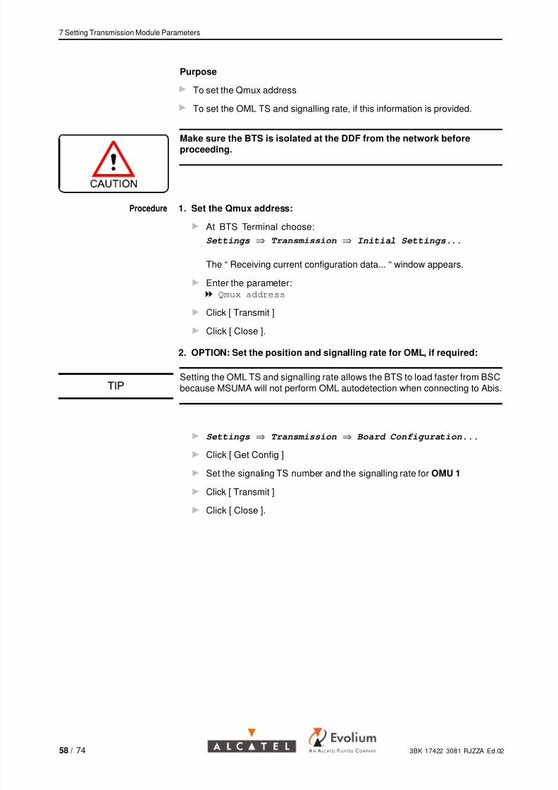
Purpose
To set the Qmux address
To set the OML TS and signalling rate, if this information is provided.
Make sure the BTS is isolated at the DDF from the network beforeproceeding.
Procedure 1. Set the Qmux address:
At BTS Terminal choose:
Settings ⇒ Transmission ⇒ Initial Settings...
The “ Receiving current configuration data... “ window appears.
Enter the parameter:Qmux address
Click [ Transmit ]
Click [ Close ].
2. OPTION: Set the position and signalling rate for OML, if required:
Setting the OML TS and signalling rate allows the BTS to load faster from BSCbecause MSUMA will not perform OML autodetection when connecting to Abis.
Settings ⇒ Transmission ⇒ Board Configuration...
Click [ Get Config ]
Set the signaling TS number and the signalling rate for OMU 1
Click [ Transmit ]
Click [ Close ].
58 / 74 3BK 17422 3081 RJZZA Ed.02

7/25/2019 A9110E UBTS Commissioning
http://slidepdf.com/reader/full/a9110e-ubts-commissioning 59/74
8 Connecting to the BSC
8 Connecting to the BSC
This chapter describes how to connect the BTS to the BSC and verify theOML status.
3BK 17422 3081 RJZZA Ed.02 59 / 74
7/25/2019 A9110E UBTS Commissioning
http://slidepdf.com/reader/full/a9110e-ubts-commissioning 60/74
8 Connecting to the BSC
Purpose To connect the BTS to the BSC and check the OML status.
Procedure 1. Connect the BTS to the BSC:
Check that the BIE connectors are connected
With BTS connected via the “ site “ distribution frame and an “ equipment
“ distribution frame: disconnect the loop between the transmit and
receive terminal blocks on the “ site “ distribution frame
With SSC option: connect the PCM cable to connectors X2, X3 and
X4 in the SSC connection area.
2. Check the state of the OML: on the SUM board check that the OML LEDis ON (indicating the OML is IT).
For further information about downloading the BTS from the BSC andnetwork integration refer to Add BTS procedure.
60 / 74 3BK 17422 3081 RJZZA Ed.02

7/25/2019 A9110E UBTS Commissioning
http://slidepdf.com/reader/full/a9110e-ubts-commissioning 61/74
9 Finishing Commissioning
9 Finishing Commissioning
This chapter describes the final operations before leaving the site.
3BK 17422 3081 RJZZA Ed.02 61 / 74
7/25/2019 A9110E UBTS Commissioning
http://slidepdf.com/reader/full/a9110e-ubts-commissioning 62/74
9 Finishing Commissioning
Purpose
To leave the site
To return the commissioning report and inventory files to base.
Procedure 1. Leave the BTS powered up2. Leave the log book on site
3. Close the COBO door
4. Reposition the front cover and lock the bottom cover (if appropriate)
5. Close the SSC door (if appropriate)
6. Check the CCL and the appendices
7. Remove all other packaging and surplus equipment.
8. Clean the site
9. Close the site and hand the keys to the key holder
10. Return the completed forms and the inventory file related to the operationto base.
62 / 74 3BK 17422 3081 RJZZA Ed.02
7/25/2019 A9110E UBTS Commissioning
http://slidepdf.com/reader/full/a9110e-ubts-commissioning 63/74
Appendix A : Abbreviations
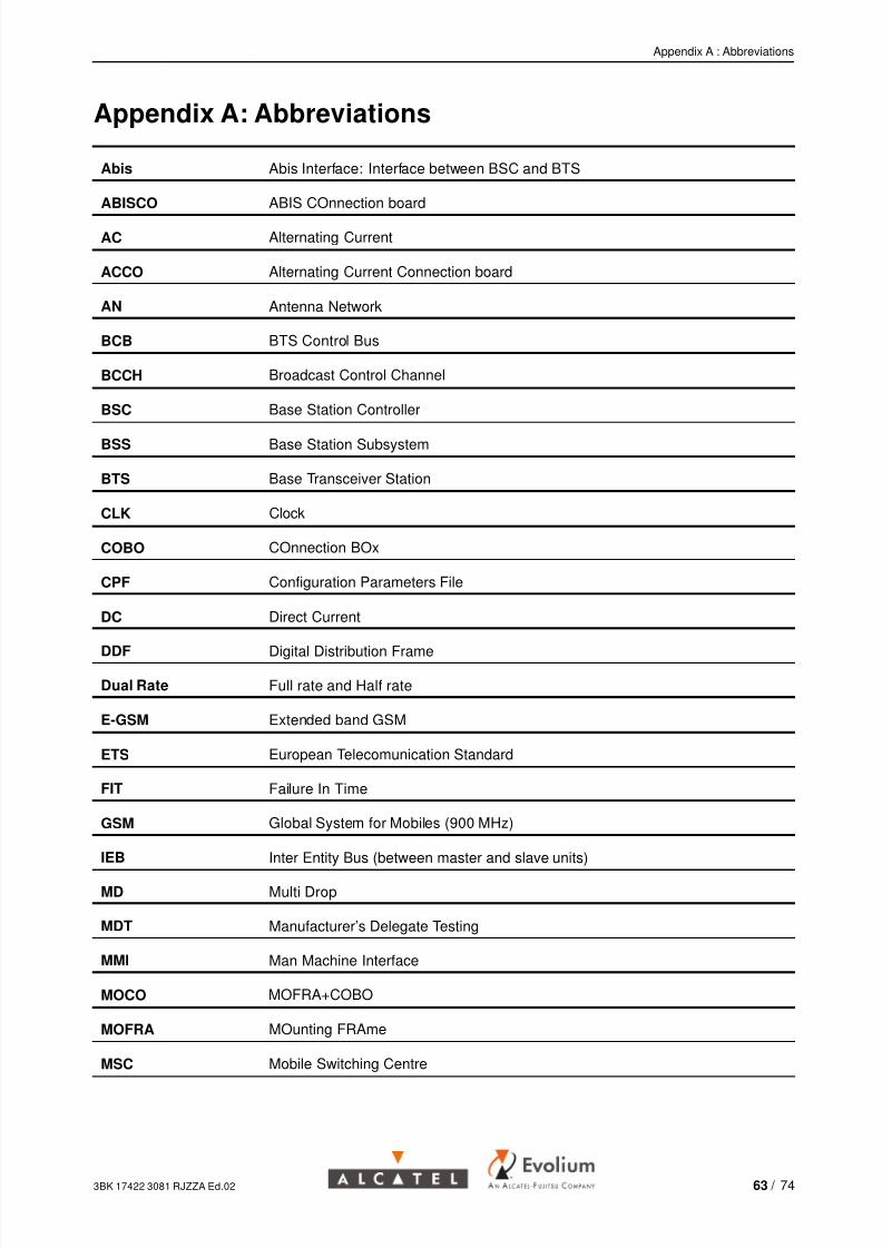
Appendix A: Abbreviations
Abis Abis Interface: Interface between BSC and BTS
ABISCO ABIS COnnection board
AC Alternating Current
ACCO Alternating Current Connection board
AN Antenna Network
BCB BTS Control Bus
BCCH Broadcast Control Channel
BSC Base Station Controller
BSS Base Station Subsystem
BTS Base Transceiver Station
CLK Clock
COBO COnnection BOx
CPF Configuration Parameters File
DC Direct Current
DDF Digital Distribution Frame
Dual Rate Full rate and Half rate
E-GSM Extended band GSM
ETS European Telecomunication Standard
FIT Failure In Time
GSM Global System for Mobiles (900 MHz)
IEB Inter Entity Bus (between master and slave units)
MD Multi Drop
MDT Manufacturer’s Delegate Testing
MMI Man Machine Interface
MOCO MOFRA+COBO
MOFRA MOunting FRAme
MSC Mobile Switching Centre
3BK 17422 3081 RJZZA Ed.02 63 / 74
7/25/2019 A9110E UBTS Commissioning
http://slidepdf.com/reader/full/a9110e-ubts-commissioning 64/74
Appendix A : Abbreviations
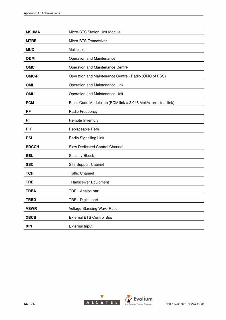
MSUMA Micro-BTS Station Unit Module
MTRE Micro-BTS Transceiver
MUX Multiplexer
O&M Operation and Maintenance
OMC Operation and Maintenance Centre
OMC-R Operation and Maintenance Centre - Radio (OMC of BSS)
OML Operation and Maintenance Link
OMU Operation and Maintenance Unit
PCM Pulse Code Modulation (PCM link = 2.048 Mbit/s terrestrial link)
RF Radio Frequency
RI Remote Inventory
RIT Replaceable ITem
RSL Radio Signalling Link
SDCCH Slow Dedicated Control Channel
SBL Security BLock
SSC Site Support Cabinet
TCH Traffic Channel
TRE TRansceiver Equipment
TREA TRE - Analog part
TRED TRE - Digital part
VSWR Voltage Standing Wave Ratio
XBCB External BTS Control Bus
XIN External Input
64 / 74 3BK 17422 3081 RJZZA Ed.02

7/25/2019 A9110E UBTS Commissioning
http://slidepdf.com/reader/full/a9110e-ubts-commissioning 65/74
Appendix B : List of Items Required
Appendix B: List of Items Required
Installation Kits The following table is used to check, on site, the mandatory or optional deliveryitem kits.
The used symbols are:
• mandatory kit
∇ technical choice kit
◊ customer option kit
Optional kits for BTS configuration Mnemo Reference Qty
◊ Integrated antenna for GSM band PUIT - ANTG 3BK 08581 AAAA 1/ unit
◊ Integrated antenna for DCS band PUIT - ANTD 3BK 08582 AAAA 1/ unit
◊ VSWR detector for GSM band VSWG 3BK 25062 AAAA 1/ ant
◊ VSWR detector for DCS band VSWD 3BK 25063 AAAA 1/ ant
.
List of DocumentsRequired
The following table is used to check, at base, the availability of the necessarydocuments.
Catalogue of Techincal and Logistic Information (ITL-PRO) 3DF 00462 0004 AAAGA
Catalogue of Instruction Operation (IO) 3DF 00300 0004 UAZZA
BSS Methods Handbook release B9 3BK 17422 0002 PCZZA
CI 08 Site Equipment Inventory 3BK 17257 0001 RJZZA
Tools Catalogue for Field Activity 3BK 20458 0001 RJZZA
Site Premises Inspection Form (CEL) 8BL 00704 0015 DRBRA
SPP 36 - Specification for Site Preparation A9110 BTS 8BL 00704 0052 DRAGA
BSS Site Premises Inspection, Post Handover 8BL 00704 0016 DRBRA
A9110 Crane HW Instruction Manual 3BK 20489 AAAA PCZZA
3BK 17422 3081 RJZZA Ed.02 65 / 74
7/25/2019 A9110E UBTS Commissioning
http://slidepdf.com/reader/full/a9110e-ubts-commissioning 66/74
Appendix B : List of Items Required
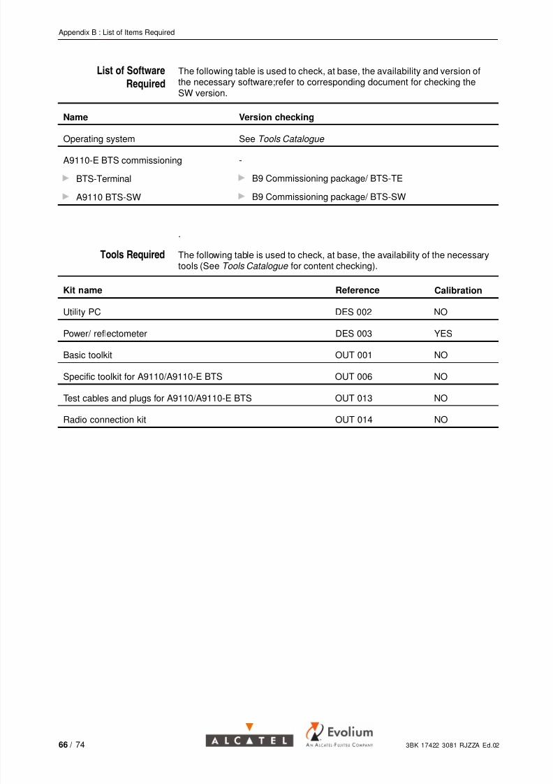
List of Software
Required
The following table is used to check, at base, the availability and version ofthe necessary software;refer to corresponding document for checking theSW version.
Name Version checking
Operating system See Tools Catalogue
A9110-E BTS commissioning
BTS-Terminal
A9110 BTS-SW
-
B9 Commissioning package/ BTS-TE
B9 Commissioning package/ BTS-SW
.
Tools Required The following table is used to check, at base, the availability of the necessarytools (See Tools Catalogue for content checking).
Kit name Reference Calibration
Utility PC DES 002 NO
Power/ reflectometer DES 003 YES
Basic toolkit OUT 001 NO
Specific toolkit for A9110/A9110-E BTS OUT 006 NO
Test cables and plugs for A9110/A9110-E BTS OUT 013 NO
Radio connection kit OUT 014 NO
66 / 74 3BK 17422 3081 RJZZA Ed.02

7/25/2019 A9110E UBTS Commissioning
http://slidepdf.com/reader/full/a9110e-ubts-commissioning 67/74
Appendix C : Description of ABISCO and ACCO Boards
Appendix C: Description of ABISCO and ACCO Boards
ABISCO Boards .
Figure 28: ABISCO Board for A9110-E
3BK 17422 3081 RJZZA Ed.02 67 / 74

7/25/2019 A9110E UBTS Commissioning
http://slidepdf.com/reader/full/a9110e-ubts-commissioning 68/74
Appendix C : Description of ABISCO and ACCO Boards
X104,X115
X105,X112
X106,X110
X107,X102
X100: MMI
X109
CALCLK
LED5: ABIS1
LED6: ABIS2
LED7*
see table
X200
LED4
BTS_LMT OK
LED1: SLAVE1
LED2: SLAVE2
LED3: MASTER
LED8 : MPSON
X108
FCLK
X211 HDSLX210 ABISTRACE
Figure 29: ABISCO Board for A9110
68 / 74 3BK 17422 3081 RJZZA Ed.02

7/25/2019 A9110E UBTS Commissioning
http://slidepdf.com/reader/full/a9110e-ubts-commissioning 69/74
Appendix C : Description of ABISCO and ACCO Boards
Connectors Description .
Figure 30: Connectors and LEDs on ABISCO
3BK 17422 3081 RJZZA Ed.02 69 / 74

7/25/2019 A9110E UBTS Commissioning
http://slidepdf.com/reader/full/a9110e-ubts-commissioning 70/74
Appendix C : Description of ABISCO and ACCO Boards
ACCO Board .
BTS fuses(T=2.5 A)
FAN fuses(T=2.5 A)
L
N
L
N
SLAVE 1SLAVE 2
X403X404
X401
X402
X400
ACout
BTS
IEC− Conn.
FAN
ACin, Mains
L
L
LL
N
NN
N
PE
PE PE
PE
Figure 31: Mechanical Drawing of ACCO
AC in
FFKDSA/V1− 7.62
(FFKDSA/V1− 7.62)
for 2.5 qmm
FFKDSA/V1− 7.62
ACo2
ACo1
X404
X403
X400
LP
T=2 x 2.5 A
T=2 x 1.25 A
GICV 2.5/ 3−GF−7.62
X402
X401
AC
AC BTS
IEC connector(cable lenght ~ 10 cm)
Figure 32: Electrical Drawing of ACCO
70 / 74 3BK 17422 3081 RJZZA Ed.02

7/25/2019 A9110E UBTS Commissioning
http://slidepdf.com/reader/full/a9110e-ubts-commissioning 71/74
Appendix D : Antenna Port and External Alarm Mapping Rules
Appendix D: Antenna Port and External Alarm MappingRules
Rules for antenna port mapping
If there is an antenna port on a micro-BTS unit (master or slave), thecorresponding field will be completed with the sector number (1...6)
If there is no antenna port (units with one antenna output or unconnected
slaves) the corresponding port will be completed with 0 (disabled)
Example 1:Master unit with no slaves, two antenna outputs 1x2:
Master port A: 1 Master port B: 1
Example 2:Master-slave configuration 3x4, no diversity
Master port A: 1 Master port B: 0
Slave 1 port A: 1 Slave 1 port B: 0
Slave 11 port A: 2 Slave 11 port B: 0
Slave 12 port A: 2 Slave 12 port B: 0
Slave 2 port A: 3 Slave 2 port B: 0
Slave 21 port A: 3 Slave 21 port B: 0
Example 3:Master-slave configuration 2x6, with diversity
Master port A: 1 Master port B: 1
Slave 1 port A: 2 Slave 1 port B: 2
Slave 11 port A: 2 Slave 11 port B: 2
Slave 12 port A: 2 Slave 12 port B: 2
Slave 2 port A: 1 Slave 2 port B: 1
Slave 21 port A: 1 Slave 21 port B: 1
3BK 17422 3081 RJZZA Ed.02 71 / 74
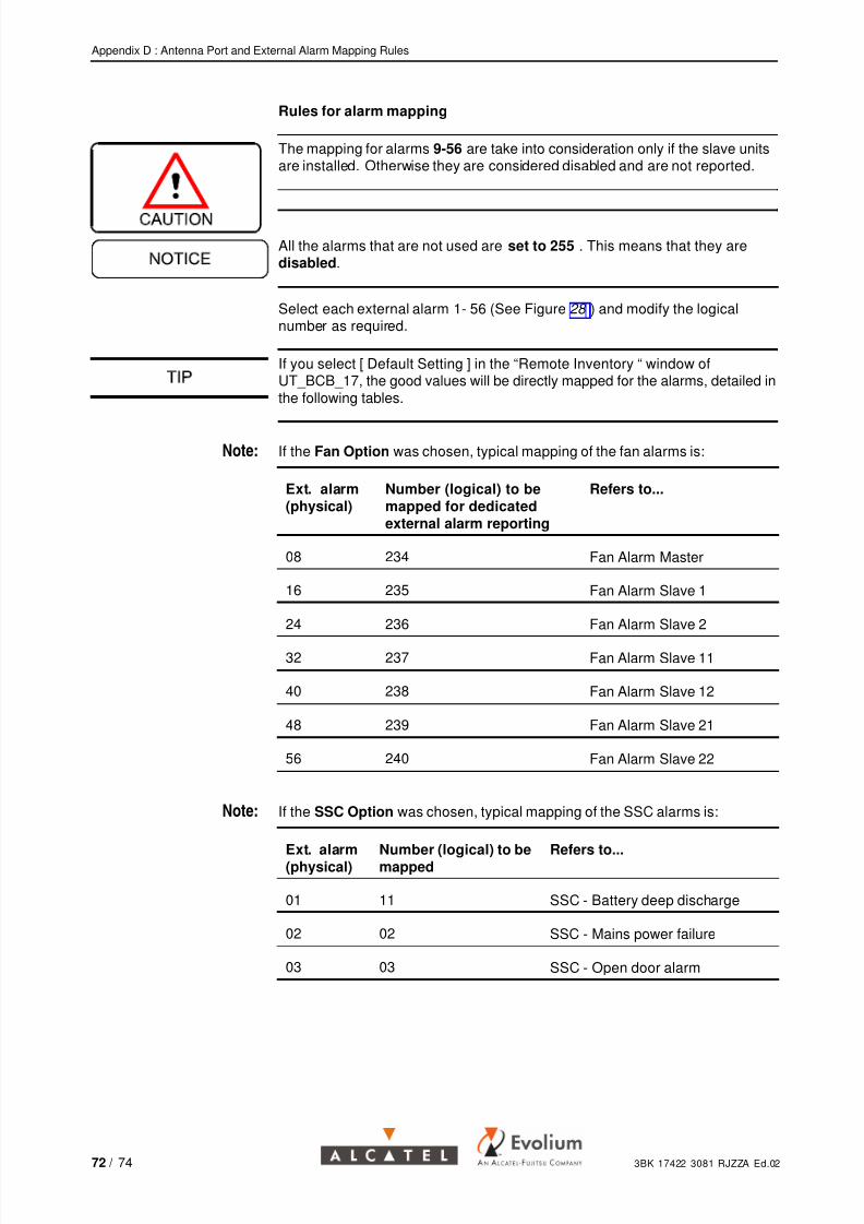
7/25/2019 A9110E UBTS Commissioning
http://slidepdf.com/reader/full/a9110e-ubts-commissioning 72/74
Appendix D : Antenna Port and External Alarm Mapping Rules
Rules for alarm mapping
The mapping for alarms 9-56 are take into consideration only if the slave unitsare installed. Otherwise they are considered disabled and are not reported.
All the alarms that are not used are set to 255 . This means that they aredisabled.
Select each external alarm 1- 56 (See Figure 28 ) and modify the logicalnumber as required.
If you select [ Default Setting ] in the “Remote Inventory “ window ofUT_BCB_17, the good values will be directly mapped for the alarms, detailed inthe following tables.
Note: If the Fan Option was chosen, typical mapping of the fan alarms is:
Ext. alarm(physical)
Number (logical) to bemapped for dedicatedexternal alarm reporting
Refers to...
08 234 Fan Alarm Master
16 235 Fan Alarm Slave 1
24 236 Fan Alarm Slave 2
32 237 Fan Alarm Slave 11
40 238 Fan Alarm Slave 12
48 239 Fan Alarm Slave 21
56 240 Fan Alarm Slave 22
Note: If the SSC Option was chosen, typical mapping of the SSC alarms is:
Ext. alarm(physical)
Number (logical) to bemapped
Refers to...
01 11 SSC - Battery deep discharge
02 02 SSC - Mains power failure
03 03 SSC - Open door alarm
72 / 74 3BK 17422 3081 RJZZA Ed.02

7/25/2019 A9110E UBTS Commissioning
http://slidepdf.com/reader/full/a9110e-ubts-commissioning 73/74
Appendix D : Antenna Port and External Alarm Mapping Rules
Note: If the VSWR Option was chosen, typical mapping of the fan alarms is:
Ext. alarm(physical)
Number (logical) to bemapped
Refers to...
06 241 VSWR1 Alarm Master (ANT A)
07 242 VSWR2 Alarm Master (ANT B)
09 243 VSWR1 Alarm Slave 1 (ANT A)
10 244 VSWR2 Alarm Slave 1 (ANT B)
17 245 VSWR1 Alarm Slave 2 (ANT A)
18 246 VSWR2 Alarm Slave 2 (ANT B)
25 247 VSWR1 Alarm Slave 11 (ANT A)
26 248 VSWR2 Alarm Slave 11 (ANT B)
33 249 VSWR1 Alarm Slave 12 (ANT A)
34 250 VSWR2 Alarm Slave 12 (ANT B)
41 251 VSWR1 Alarm Slave 21 (ANT A)
42 252 VSWR2 Alarm Slave 21 (ANT B)
49 253 VSWR1 Alarm Slave 22 (ANT A)
50 254 VSWR2 Alarm Slave 22 (ANT B)
Note: Other alarms to be mapped:
Ext. alarm (physical) Ext. alarm (logical) Refers to...
04 04 Door Alarm Master
05 05 PMS Alarm Master
12 12 Door Alarm Slave 1
13 13 PMS Alarm Slave 1
20 20 Door Alarm Slave 2
21 21 PMS Alarm Slave 2
28 28 Door Alarm Slave 11
29 29 PMS Alarm Slave 11
36 36 Door Alarm Slave 12
37 37 PMS Alarm Slave 12
3BK 17422 3081 RJZZA Ed.02 73 / 74

7/25/2019 A9110E UBTS Commissioning
http://slidepdf.com/reader/full/a9110e-ubts-commissioning 74/74
Appendix D : Antenna Port and External Alarm Mapping Rules
Ext. alarm (physical) Ext. alarm (logical) Refers to...
44 44 Door Alarm Slave 21
45 45 PMS Alarm Slave 21
52 52 Door Alarm Slave 22
53 53 PMS Alarm Slave 22
11, 14, 15, 19, 22, 23, 27,30, 31, 35, 38, 39, 43, 46,47, 51, 52, 55
255 — Disabled —
Depending on the options installed, the alarm mapping can be changedaccording to the site situation.