Embed Size (px)
Citation preview

A19 / A1058 Coast Road Junction Improvement Scheme
TENDER DOCUMENTS VOLUME 3D
WORKS INFORMATION – SPECIFICATION (Main Junction Improvement Works)
May 2015

A19 / A1058 Coast Road Junction Improvement Tender Documents Volume 3D Highways England Works Information - Specification
Version 1.0 Page i May 2015
WORKS INFORMATION – SPECIFICATION
CONTENTS
Preamble to the Specification 1
Appendix 0/1 - Contract specific Additional, Substitute and Cancelled Clauses, Tables and Figures Included in the Contract
3
Appendix 0/2 - Contract specific Minor Alterations to Existing Clauses, Tables and Figures Included in the Contract
11
Appendix 0/3 - List of contract specific Numbered Appendices Referred to in the Specification and Included in the Contract
12
Appendix 0/4 - List of Drawings Included in the Contract 21
Appendix 1/1 - Temporary Accommodation and Equipment for the Overseeing Organisation
35
Appendix 1/2 - Vehicles for the Overseeing Organisation 43
Appendix 1/3 - Radio Communication System for the Overseeing Organisation
45
Appendix 1/4- Working and Fabrication Drawings 46
Appendix 1/5 - Testing to be Carried out by the Contractor 47
Appendix 1/6 - Supply and Delivery of Samples to the Overseeing Organisation
80
Appendix 1/7 - Site Extent and Limitations on Use 81
Appendix 1/8 - Operatives for the Overseeing Organisation 83
Appendix 1/9 - Control of Noise and Vibration 84
Appendix 1/10 - Permanent Works to be Designed by the Contractor 86
Appendix 1/11 - Temporary Works Design 88
Appendix 1/12 - Setting Out and Existing Ground Levels 89
Appendix 1/13 - Programme of Works 90
Appendix 1/14 - Payment Applications 92
Appendix 1/16 - Privately and Publicly Owned Services and Supplies 93
Appendix 1/17 - Traffic Safety and Management 98

A19 / A1058 Coast Road Junction Improvement Tender Documents Volume 3D Highways England Works Information - Specification
Version 1.0 Page ii May 2015
Appendix 1/18 - Temporary Highways for Traffic 112
Appendix 1/19 - Routeing of Vehicles 115
Appendix 1/20 - Recovery Vehicles for Breakdowns 116
Appendix 1/21 - Information Boards 122
Appendix 1/22 - Progress Photographs 123
Appendix 1/23 - Risks to Health and Safety 125
Appendix 1/24 - Quality Management System 127
Appendix 1/25 - Temporary Closed Circuit Television (CCTV) System for the Monitoring of Traffic
129
Appendix 1/27 - Temporary Automatic Speed Camera System for the Enforcement of Mandatory Speed Limits at Road Works (TASCAR)
130
Appendix 1/70 - List of Buildings to be Surveyed 132
Appendix 2/1 - List of Buildings, etc., to be Demolished or Partially Demolished
134
Appendix 2/2 - Filling of Trenches and Pipes 135
Appendix 2/3 - Retention of Material Arising from Site Clearance 136
Appendix 2/4 - Explosives and Blasting 137
Appendix 2/5 - Hazardous Materials 138
Appendix 3/1 - Fencing, Gates and Stiles 139
Appendix 4/1 - Road Restraint Systems (Vehicle and Pedestrian) 140
Appendix 4/2 - Information Required to Demonstrate Compliance of Road Restraint Systems to BS EN 1317-1, BS EN 1317-2, BS EN 1317-3 and DD ENV 1317-4: 2002
161
Appendix 5/1 - Drainage Requirements 167
Appendix 5/2 - Service Duct Requirements 191
Appendix 5/4 - Fin Drains and Narrow Filter Drains 193
Appendix 5/5 - Combined Drainage and Kerb Systems 195
Appendix 5/6 - Linear Drainage Channel Systems 197
Appendix 5/7 - Thermoplastics Structural Wall Pipes and Fittings 198
Appendix 6/1 - Requirements for Acceptability & Testing etc. of Earthworks 202

A19 / A1058 Coast Road Junction Improvement Tender Documents Volume 3D Highways England Works Information - Specification
Version 1.0 Page iii May 2015
Materials
Appendix 6/2 - Requirements for Dealing with Class U1B and Class U2 Unacceptable Materials
216
Appendix 6/3 - Requirements for Excavation, Deposition, Compaction (Other than Dynamic Compaction)
217
Appendix 6/6 - Fill to Structures and Fill Above Structural Foundations 219
Appendix 6/7 - Sub-formation and Capping and Preparation and Surface Treatment of Formation
220
Appendix 6/8 - Topsoiling 221
Appendix 6/12 – Instrumentation and Monitoring 222
Appendix 6/14 - Limiting Values for Pollution of Controlled Waters 224
Appendix 6/15 - Limiting Values for Harm to Human Health and the Environment
225
Appendix 7/1 - Permitted Pavement Options 227
Appendix 7/2 - Excavation, Trimming and Reinstatement of Existing Surfaces
236
Appendix 7/4 - Bond Coats, Tack Coats and Other Bituminous Sprays 237
Appendix 7/6 - Breaking Up or Perforation of Existing Pavement 240
Appendix 7/9 - Cold-Milling (Planing) of Bituminous Bound Flexible Pavement
241
Appendix 7/22 - Repairs to Potholes 242
Appendix 11/1 - Kerbs, Footways & Paved Areas 243
Appendix 11/2 - Access Steps 244
Appendix 12/1 - Traffic Signs: General 245
Appendix 12/2 - Traffic Signs: Marker Posts 247
Appendix 12/3 - Traffic Signs: Road Markings and Studs 248
Appendix 12/4 - Traffic Signs: Cones, Cylinders, FTD's and Other Traffic Delineators
251
Appendix 12/5 - Traffic Signs: Traffic Signals 252
Appendix 12/6 - Traffic Signs: Special Sign Requirements on Gantries 258
Appendix 13/1 - Information to be Provided When Specifying Lighting Columns and Brackets
259
Appendix 13/2 - (Specification for Highway Works) Typical Lighting Column and Bracket Data Sheets 1 and 2
262

A19 / A1058 Coast Road Junction Improvement Tender Documents Volume 3D Highways England Works Information - Specification
Version 1.0 Page iv May 2015
Appendix 13/3 - Instructions for Completion of Lighting Column and Bracket Data Sheets
264
Appendix 13/4 - Information to be Provided When Specifying CCTV Masts 265
Appendix 13/5 - (Specification for Highway Works) Typical CCTV Mast Data Sheet
266
Appendix 13/6 - Instructions for Completion of CCTV Mast Sheets 267
Appendix 13/8 - (Specification for Highway Works) Typical Cantilever Masts Data Sheets 1 and 2
268
Appendix 13/9 - Instructions for Completion of Cantilever Masts Data Sheets
270
Appendix 14/1 - Site Records 271
Appendix 14/2 - Location of Lighting Units and Feeder Pillars 272
Appendix 14/3 - Temporary Lighting 274
Appendix 14/4 - Electrical Equipment for Road Lighting 275
Appendix 14/5 - Electrical Equipment for Traffic Signs 280
Appendix 15/1 - Motorway Communications 281
Appendix 15/2 - Cable Duct Requirements 292
Appendix 16/1 - General Requirements for Piling and Embedded Retaining Walls
295
Appendix 16/3 - Bored Cast-in Place Piles 297
Appendix 16/8 - Non-Destructive Methods for Testing Piles 298
Appendix 16/9 - Static Load Testing of Piles 300
Appendix 16/13 - Contiguous Bored Pile Walls 301
Appendix 16/15 - Steel Sheet Piles 302
Appendix 16/17 - Instrumentation for Piles and Embedded Walls 304
Appendix 17/1 - Schedule for the Specification of Designed Concrete 305
Appendix 17/3 - Concrete - Surface Finishes 308
Appendix 17/4 - Concrete - General 310
Appendix 17/5 - Buried Concrete 312
Appendix 18/1 - Requirements for Structural Steelwork 313
Appendix 19/1 - (Specification for Highway Works) Form HA/P1 (New Works) Paint System Sheet
335

A19 / A1058 Coast Road Junction Improvement Tender Documents Volume 3D Highways England Works Information - Specification
Version 1.0 Page v May 2015
Appendix 19/2 - Requirements for Other Work 338
Appendix 19/3 - (Specification for Highway Works) Form HA/P2 Paint Data Sheet
340
Appendix 19/5 - General Requirements 341
Appendix 20/1 - Waterproofing for Concrete Structures 342
Appendix 21/1 - Bridge Bearing Schedule 343
Appendix 23/1 - Bridge Deck Expansion Joints Schedule 344
Appendix 23/2 - Sealing of Gaps Schedule (Other than in Bridge Deck Expansion Joints)
345
Appendix 24/1 - Brickwork, Blockwork and Stonework 346
Appendix 25/1 - Requirements for Corrugated Steel Buried Structures 347
Appendix 25/5 - Requirements for Buried Rigid Pipes for Drainage Structures
348
Appendix 26/1 - Ancillary Concrete 349
Appendix 26/2 - Bedding Mortar 351
Appendix 26/3 - Cored Thermoplastic Node Markers 352
Appendix 30/1 - General 353
Appendix 30/2 - Weed Control 357
Appendix 30/3 – Control of Rabbits and Deer 359
Appendix 30/4 - Ground Preparation 360
Appendix 30/5 - Grass Seeding, Wildflower Seeding and Turfing 362
Appendix 30/6 - Planting 365
Appendix 30/7 - Grass, Bulbs and Wildflower Maintenance 370
Appendix 30/8 - Watering 372
Appendix 30/9 - Establishment Maintenance for Planting 373
Appendix 30/10 - Maintenance of Established Trees and Shrubs 374

A19 / A1058 Coast Road Junction Improvement Tender Documents Volume 3D Highways England Works Information - Specification
Version 1.0 Page 1 May 2015
Preamble to the Specification
1 The Specification referred to in the Tender shall be the ‘Specification for Highway Works’, published by the Stationery Office (formerly HMSO) as Volume 1 of the Manual of Contract Documents for Highway Works, as modified and extended by the following contract specific items:
(i) Appendix 0/1: Contract specific Additional, Substitute and Cancelled Clauses, Tables and Figures;
(ii) Appendix 0/2: Contract specific minor alterations to existing Clauses, Tables and Figures;
(iii) The contract specific Numbered Appendices listed in Appendix 0/3;
(iv) Appendix 0/5: Special National Alterations of the Overseeing Organisation of Scotland, Wales or Northern Ireland.
Appendix 0/4 contains a list of the Drawings.
2 The relevant publication date of each page of the Specification for Highway Works is given in the Schedule of Pages and Relevant Publication Dates.
3 An Additional Clause as indicated by a suffix ‘A’ in Appendix 0/5 is an alteration originating from the Overseeing Organisation of Scotland, Wales or Northern Ireland. An Additional Clause as indicated by a suffix ‘AR’ in Appendix 0/1 is a contract specific alteration.
4 A Substitute Clause, as indicated by the suffix ‘S’ in Appendix 0/5 is an alteration originating from the Overseeing Organisation of Scotland, Wales or Northern Ireland. A Substitute Clause as indicated by a suffix ‘SR’ in Appendix 0/1 is a contract specific alteration.
5 A Cancelled Clause as indicated by a suffix ‘C’ in Appendix 0/5 is an alteration originating from the Overseeing Organisation of Scotland, Wales or Northern Ireland. A Cancelled Clause indicated by a suffix ‘CR’ in Appendix 0/1 is a contract specific alteration.
6 Insofar as any of the contract specific Numbered Appendices may conflict or be inconsistent with any provision of the Specification for Highway Works the Numbered Appendices shall always prevail. Additionally, Numbered Appendices 0/1 and 0/2 shall take precedence over Numbered Appendix 0/5.
7 Any reference in the Contract to a Clause number or contract specific Appendix shall be deemed to refer to the corresponding Substitute Clause number or contract specific Appendix listed in Appendix 0/1, 0/2 or 0/5.
8 Where a Clause is altered any original Table/Figure referred to in the Clause shall apply unless the Table/Figure is also altered. Where a Table/Figure is altered any reference in a Clause to the original Table/Figure shall apply to the altered Table/Figure.
9 Where a Clause in the Specification relates to work goods or materials which are not required for the Works it shall be deemed not to apply.
10 Any Appendix referred to in the Specification which is not used shall be deemed not to apply.
11 Where a Clause in the Specification is prefixed by an # this indicates that this particular Clause has a substitute National Alteration for one or more of the Overseeing Organisations of Scotland, Wales or Northern Ireland. Substitute or additional National Clauses shall be used within countries to which they

A19 / A1058 Coast Road Junction Improvement Tender Documents Volume 3D Highways England Works Information - Specification
Version 1.0 Page 2 May 2015
specifically apply and they are deemed to replace corresponding Clauses in the main text of the Specification as appropriate. The substitute National Clauses are located at the end of the relevant Series together with the additional National Clauses of the Overseeing Organisations.
12 Other than where references to the Overseeing Organisation are made in the context of the Overseeing Organisation granting statutory or type approvals, the roles and functions of the Overseeing Organisation shall be undertaken by the Project Manager.
Where the Specification requires the provision of documentation to the Overseeing Organisation for statutory or type approval such documentation shall be provided to the Project Manager.
13 If the Specification is used in conjunction with a Contract under which the Contractor is responsible for the design of any part of the Permanent Works, the delegation of the roles and functions of the Project Manager as stated in paragraph 12 above shall be further amended as follows:
(i) If any agreement, consent or approval required to be obtained from the Overseeing Organisation impacts on the health and safety of the general public, the environment or any property or equipment not owned or operated by the Contractor, such agreement, consent, approval shall be obtained from Project Manager.
(ii) Where the Specification provides for the Overseeing Organisation to require a test, waive the requirement for a test or alter testing frequency, the party to whom the Overseeing Organisation’s roles and functions have been ascribed by paragraph 12 above shall exercise such decisions in accordance with the Secretary of State’s requirements stated in the Contract. 4
14 Where Standards and other documents are incorporated into the Contract by reference the respective edition used shall be that which is current on the Contract Reference Document Date 18th May 2015 unless otherwise stated in the Specification.

A19 / A1058 Coast Road Junction Improvement Tender Documents Volume 3D Highways England Works Information - Specification
Version 1.0 Page 3 May 2015
APPENDIX 0/1: CONTRACT-SPECIFIC ADDITIONAL, SUBSTITUTE AND CANCELLED CLAUSES, TABLES AND FIGURES INCLUDED IN THE CONTRACT
PART A: VOLUME 1 SPECIFICATION List of Additional Clauses, Tables and Figures
Clause Number (etc.)
Title Written on Page Number
following
127 AR Protection from Nuisance due to the works 4
128 AR Publicity and Disclosure of Information 4
129 AR Survey of Existing Properties 5
170 AR Safety for Works in Sewers, Pipes and Underground Chambers Etc. 6
180 AR Working with Others 6
181 AR Health and Safety Requirements 7
182 AR Documents 8
183 AR Handover Documents at Completion 8
184 AR Provision of Cost Information 8
2608 AR Non-Flowing or Dry Pack Bedding Mortars 9
List of Substitute Clauses, Tables and Figures
Clause Number (etc.)
Title Written on Page Number
following
None
List of Cancelled Clauses, Tables and Figures
Clause Number (etc.)
Title
None

A19 / A1058 Coast Road Junction Improvement Tender Documents Volume 3D Highways England Works Information - Specification
Version 1.0 Page 4 May 2015
Additional Clauses, Tables and Figures
Clause Number (etc.)
Title and written text
127 AR Protection from Nuisance due to the Works
Existing roads, footways, rights of way, accesses to adjacent properties, buildings, etc., and any new roads and drains, whether part of the Site or not, which are being used by any of the Contractor’s or his Sub-Contractors’ or Suppliers’ vehicles or items of plant in connection with the works, shall be kept clean and free from all dirt, mud and material dropped from vehicles or tyres and tracks.
Suitable wheel washing facilities shall be provided and used at all Contractor’s, Sub-Contractors’ and Suppliers’ points of entry onto the public highway from the Site. No vehicle which is likely to deposit mud or other material on the road surface shall be permitted back onto the public highway. In meeting his obligations under the Conditions of Contract, the Contractor shall provide, maintain and use as necessary suitable equipment, including mechanical/vacuum road sweepers throughout the duration of the works. Road sweepers propelled by tractors and with the brush at an angle to the road will not be permitted.
128 AR Publicity and Disclosure of Information
1. The Contractor shall not give any information concerning the Works for publication in the press or on radio, television or screen or elsewhere without the written approval of the Project Manager.
2. All advertisements and Contractor’s or Sub-Contractors’ name-boards to be erected within the Site by the Contractor or by any Sub-Contractor shall first be approved by the Project Manager.
3. The Contractor shall not take or cause to have taken any photographs of the Works without the permission of the Project Manager.
If such permission is given, the Contractor shall supply to the Project Manager, free of charge, duplicate copies of all photographs taken by him and shall print on the reverse side of such photographs the date of exposure, the section of the Works shown, any reference number and the address and contact details for where the original file is stored.

A19 / A1058 Coast Road Junction Improvement Tender Documents Volume 3D Highways England Works Information - Specification
Version 1.0 Page 5 May 2015
Clause Number (etc.)
Title and written text
129 AR Survey of Existing Properties
1. Prior to the commencement of Works in the vicinity of properties referred to in Appendix 1/70 the Contractor shall make arrangements and, accompanied by the title holder or his appointed representative, compile schedules of conditions (together with photographs) of the properties.
2. A representative of the Overseeing Organisation shall be present at all inspections, and the Contractor shall give seven days’ notice of his intention to carry out such inspections.
3. Two copies of the Schedules of Conditions, including photographs, signed by the owner or tenant shall be forwarded to the Project Manager two weeks prior to any work being commenced in the vicinity of the properties concerned
4. The Schedules of Conditions, etc., are to be compiled by a suitably experienced and competent person undertaking property and structural surveys and being a chartered member of any of the following Institutions:-
• The Royal Institution of Chartered Surveyors • Royal Association of British Architects • The Chartered Institute of Building • The Institution of Civil Engineers • The Institution of Structural Engineers
Appointed under fee competition involving a least 3 quotations and approved by the Project Manager.
5. The reasonable fees of the surveyor appointed in accordance with paragraph 3 above, shall be paid by the Contractor who will be reimbursed all such monies approved by the Project Manager.
6. The detail of the survey shall be as described below:
i) A minimum of 10 photographs, 175 mm x 125 mm, to be taken per property giving a general indication of cracking, structural damage or defects and any other visual faults.
ii) The length and width of cracks to be assessed accurately. Structural cracks to be monitored throughout the currency of the Contract with approved ‘tell-tale’ devices.
iii) Both the interior and exterior of the properties to be surveyed together with the state and conditions of outbuildings, garages, garden sheds, greenhouses, boundary walls and fencing and the like.
iv) A copy of the completed survey (Schedule of Conditions etc.) will be furnished to the owner or tenant of each property.
v) All photographs to be presented in albums clearly annotated as to property number, owner’s name, particular aspect of view etc.

A19 / A1058 Coast Road Junction Improvement Tender Documents Volume 3D Highways England Works Information - Specification
Version 1.0 Page 6 May 2015
Additional Clauses, Tables and Figures Continued
Clause Number (etc.)
Title and written text
129 AR
Cont’d
vi) Particular attention should be given to the cellars as to their location in relation to the garden wall and the size and location of cellar skylights. Cellar’s dimensions to be provided.
vii) The survey report shall be issued separately for each property.
6. All photographs are to be in colour.
7. The survey shall be repeated upon completion of the Works or as directed by the Project Manager.
8. The amount of insurances and indemnity and the period for which the surveyor maintains insurances are:-
• Public liability of £10 million • Overseeing Organisations Liability of £5 million • Professional indemnity of £1 million
Period following completion of the whole of the services or earlier completion – 12 months.
170 AR Safety For Work In Sewers, Pipes And Underground Chambers Etc.
1. Where work is to be carried out within or adjacent to foul sewers, pipes or underground chambers and anywhere else where dangerous gases may be encountered the Contractor shall comply with the applicable safety at work provisions of the relevant Authority or Client.
180 AR Working With Others
1. The Contractor shall
• register the Site under the Considerate Constructor Scheme and
• comply with the Considerate Constructor Scheme’s Code of Considerate Practice in Providing the works
2. The Contractor complies with the special requirements of Statutory Undertakers as stated in the Works Information.
3. The Contractor cooperates with, and shares the Working Areas with the following organisations:
• The Overseeing Organisation’s other contractors including the Area 14 MAC (currently A One +)
• Utility companies carrying out Works required by this contract
• Any other organisation identified by the Overseeing Organisation

A19 / A1058 Coast Road Junction Improvement Tender Documents Volume 3D Highways England Works Information - Specification
Version 1.0 Page 7 May 2015
Additional Clauses, Tables and Figures Continued
Clause Number (etc.)
Title and written text
181 AR Health & Safety Requirements General
1. Requirements for health and safety include those given in Numbered Appendices 1/17, 1/18, 1/19 and 1/23.
2. The Contractor operates an occupational health management system in line with the requirements of HSE’s construction occupational health management model.
Client
3. In accordance with the Conditions of Contract Highways England will undertake the role of the Client under the Construction (Design and Management) Regulations 2007.
Principal Contractor
4. The Employer appoints the Contractor to act as Principal Contractor and CDM coordinator for the purposes of the Construction (Design and Management) Regulations 2007. The Contractor provides information to the Project Manager to demonstrate that individuals proposed for appointment to carry out the duties of the CDM coordinator meet the criteria in the Health and Safety Executive's Approved Code of Practice (L114), "Managing Health and Safety in Construction".
Pre-construction Health and Safety Information
5. The Principal Designer shall develop the Pre-Construction Information Pack which shall be prepared in accordance with CDM (2007).
6. Before commencing the construction phase of the works, the Contractor confirms to the Project Manager that adequate welfare facilities are in place.
Health and Safety File
7. The Principal Contractor shall forward information for the Health and Safety File to the Principal Designer. The Contractor will be required to invite the Principal Designer to design meetings.
8. The Principal Designer issues the information in the Health and Safety File to the Project Manager at Completion
9. The Contractor issues the information required for the Health and Safety file to the Project Manager in accordance with Highway England’s handover procedures as described in the Works Information.

A19 / A1058 Coast Road Junction Improvement Tender Documents Volume 3D Highways England Works Information - Specification
Version 1.0 Page 8 May 2015

A19 / A1058 Coast Road Junction Improvement Tender Documents Volume 3D Highways England Works Information - Specification
Version 1.0 Page 9 May 2015
Additional Clauses, Tables and Figures Continued
Clause Number (etc.)
Title and written text
181 AR Cont’d
10. The Contractor reports to the Overseeing Organisation and the Project Manager as soon as he is aware, and in any event within twenty four hours, details of any incidents on the Site which:
• involve any person being injured or killed in connection with the Works on the Site;
• result in unplanned lane closures;
• have an impact on the operations of a third party;
The Contractor reports such incidents verbally and by email, and additionally reports all incidents through the Highway’s England Accident and Incident Reporting System. (formerly known as HA AIRS).
182 AR Documents
1. The Contractor returns the Works Information or any other material relating to the Works to the Project Manager at the defects date
2. Any paper the Parties use in connection with this contract is to contain at least 80% post-consumer waste and be printed on both sides where appropriate.
3. Except where otherwise noted the Contractor shall submit two hard copies and one electronic copy of all submissions. The electronic copy shall be in a format and stored on media to be agreed with the Project Manager.
183 AR Handover Documents At Completion
1. The Contractor provides the handover documents at the time required by and in accordance with Highways England current procedures and in accordance with the requirements in the Works Information.
184 AR Provision Of Cost Information
1. The Contractor completes Highways England electronic cost control forms and submits the completed forms to the Project Manager within one week of each assessment date.
2. The Contractor provides data relating to quantities and cost in accordance with the Highways England’s Cost Capture Process.

A19 / A1058 Coast Road Junction Improvement Tender Documents Volume 3D Highways England Works Information - Specification
Version 1.0 Page 10 May 2015
Additional Clauses, Tables and Figures Continued
Clause Number (etc.)
Title and written text
2608 AR Non-flowing or Dry Pack Bedding Mortars
1. Non-flowing or dry pack bedding Cementitous or resinous (epoxy) mortars can be used as a substitute for free flowing bedding mortars which are covered under Cl. 2601 of the SHW. Proprietary non-flowing or dry pack mortars should be used in accordance with the manufacturer’s recommendations and instructions.
2. Non-flowing or dry pack bedding mortars shall conform to the Cl 2601:2 (Materials) and Cl. 2601:3 (Site Mixing, Placing and Curing) of the SHW.
3. A methodology to demonstrate that the mortar will have full penetration under the bearings should be provided.
4. Non-flowing or dry pack bedding mortars shall be tested for the following Laboratory Approval Tests in accordance with Cl. 2601:4 of the SHW.
Compressive Strength
Expansion Test
Water Absorption Test
5. Non-flowing or dry pack bedding mortars shall be tested for the following Site Control Test in accordance with Cl. 2601:5 of the SHW.
Compressive Strength
6. The tolerances specified in Cl. 2601:6 of the SHW shall apply to all temperatures referred to in this Clause.
Substitute Clauses, Tables and Figures
Clause Number
(etc.)
Title and rewritten text
None

A19 / A1058 Coast Road Junction Improvement Tender Documents Volume 3D Highways England Works Information - Specification
Version 1.0 Page 11 May 2015
PART B: VOLUME 2 NOTES FOR GUIDANCE ON THE SPECIFICATION FOR HIGHWAY WORKS List of Additional Clauses, Tables and Figures
Clause Number
(etc.)
Title Written on Page Number
following
None
List of Substitute Clauses, Tables and Figures
Clause Number
(etc.)
Title Written on Page Number
following
None
List of Cancelled Clauses, Tables and Figures
Clause Number
(etc.)
Title
None
Additional Clauses, Tables and Figures
Clause Number
(etc.)
Title and written text
None
Substitute Clauses, Tables and Figures
Clause Number
(etc.)
Title and rewritten text
None
A19 / A1058 Coast Road Junction Improvement Tender Documents Volume 3D Highways England Works Information - Specification
Version 1.0 Page 12 May 2015
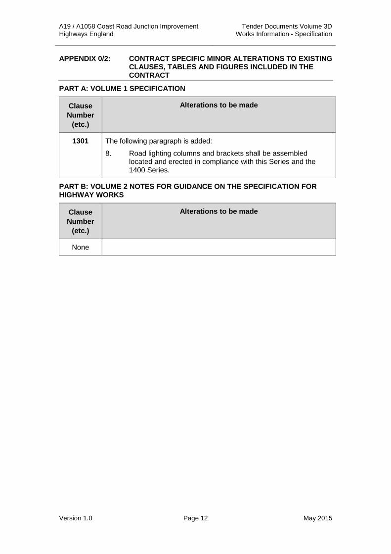
APPENDIX 0/2: CONTRACT SPECIFIC MINOR ALTERATIONS TO EXISTING CLAUSES, TABLES AND FIGURES INCLUDED IN THE CONTRACT
PART A: VOLUME 1 SPECIFICATION
Clause Number
(etc.)
Alterations to be made
1301 The following paragraph is added:
8. Road lighting columns and brackets shall be assembled located and erected in compliance with this Series and the 1400 Series.
PART B: VOLUME 2 NOTES FOR GUIDANCE ON THE SPECIFICATION FOR HIGHWAY WORKS
Clause Number
(etc.)
Alterations to be made
None

A19 / A1058 Coast Road Junction Improvement Tender Documents Volume 3D Highways England Works Information - Specification
Version 1.0 Page 13 May 2015
APPENDIX 0/3: LIST OF CONTRACT SPECIFIC NUMBERED APPENDICES REFERRED TO IN THE SPECIFICATION AND INCLUDED IN THE CONTRACT
Appendix 0/3 is comprised of two lists, A and B, of Numbered Appendices as follows.
List ‘A’ is a complete list of the Numbered Appendices referred to in the Specification for Highway Works and used in the Contract. Those identified by the letters ‘T’ or ‘C’ shall be compiled by the Tenderer or the Contractor respectively.
List ‘B’ gives a list of Contract–specific Numbered Appendices devised for the Contract.

A19 / A1058 Coast Road Junction Improvement Tender Documents Volume 3D Highways England Works Information - Specification
Version 1.0 Page 14 May 2015
List A – Contract Specific Numbered Appendices Referred to in the Specification for Highway Works and Included in the Contract
Volume Number
Completed By
Appendix Number
Title
INTRODUCTION
3D Co 0/1 Contract specific Additional, Substitute and Cancelled Clauses, Tables and Figures Included in the Contract
3D Co 0/2 Contract specific Minor Alterations to Existing Clauses, Tables and Figures Included in the Contract
3D Co 0/3 List of contract specific Numbered Appendices Referred to in the Specification and Included in the Contract
3D Co 0/4 List of Drawings Included in the Contract
Not Used 0/5 Special National Alterations of the Overseeing Organisations of Scotland / Wales / Northern Ireland
PRELIMINARIES
3D Co 1/1 Temporary Accommodation and Equipment for the Overseeing Organisation
3D Co 1/2 Vehicles for the Overseeing Organisation
3D Co 1/3 Radio Communication System for the Overseeing Organisation
3D Co 1/4 Working and Fabrication Drawings
3D Co/C 1/5 Testing to be Carried out by the Contractor
3D Co 1/6 Supply and Delivery of Samples to the Overseeing Organisation
3D Co 1/7 Site Extent and Limitations on Use
3D Co 1/8 Operatives for the Overseeing Organisation
3D Co 1/9 Control of Noise and Vibration
3D Co 1/10 Permanent Works to be Designed by the Contractor
3D Co 1/11 Temporary Works Design
3D Co 1/12 Setting Out and Existing Ground Levels
3D Co 1/13 Programme of Works
3D Co 1/14 Payment Applications
Not Used 1/15 Accommodation Works
3D Co 1/16 Privately and Publicly Owned Services and Supplies
3D Co 1/17 Traffic Safety and Management
3D Co 1/18 Temporary Highways for Traffic
3D Co 1/19 Routeing of Vehicles
3D Co/C 1/20 Recovery Vehicles for Breakdowns
3D Co 1/21 Information Boards

A19 / A1058 Coast Road Junction Improvement Tender Documents Volume 3D Highways England Works Information - Specification
Version 1.0 Page 15 May 2015
List A – Contract Specific Numbered Appendices Referred to in the Specification for Highway Works and Included in the Contract Continued
Volume Number
Completed By
Appendix Number
Title
3D Co 1/22 Progress Photographs
3D Co 1/23 Risks to Health and Safety
3D Co 1/24 Quality Management System
3D Co 1/25 Temporary Closed Circuit Television (CCTV) System for the Monitoring of Traffic
Not Used 1/26 Not Used
3D Co 1/27 Temporary Automatic Speed Camera System for the Enforcement of Mandatory Speed Limits at Road Works (TASCAR)
3D Co 1/70 List of Buildings to be Surveyed
SITE CLEARANCE
3D Co 2/1 List of Buildings, etc., to be Demolished or Partially Demolished
3D Co 2/2 Filling of Trenches and Pipes
3D Co 2/3 Retention of Material Arising from Site Clearance
3D Co 2/4 Explosives and Blasting
3D Co 2/5 Hazardous Materials
FENCING
3D Co 3/1 Fencing, Gates and Stiles
ROAD RESTRAINT SYSTEMS (VEHICLE AND PEDESTRIAN)
3D Co 4/1 Road Restraint Systems (Vehicle and Pedestrian)
3D Co / C 4/2 Information Required to Demonstrate Compliance of Road Restraint Systems to BS EN 1317-1, BS EN 1317-2, BS EN 1317-3 and DD ENV 1317-4: 2002
DRAINAGE AND SERVICE DUCTS
3D Co 5/1 Drainage Requirements
3D Co 5/2 Service Duct Requirements
3D Co 5/3 Surface Water Channels and Drainage Channel Blocks
3D Co 5/4 Fin Drains and Narrow Filter Drains
3D Co 5/5 Combined Drainage and Kerb Systems
3D Co 5/6 Linear Drainage Channel Systems
3D Co 5/7 Thermoplastics Structural Wall Pipes and Fittings
EARTHWORKS
3D Co 6/1 Requirements for Acceptability & Testing etc. of Earthworks Materials

A19 / A1058 Coast Road Junction Improvement Tender Documents Volume 3D Highways England Works Information - Specification
Version 1.0 Page 16 May 2015
List A – Contract Specific Numbered Appendices Referred to in the Specification for Highway Works and Included in the Contract Continued
Volume Number
Completed By
Appendix Number
Title
3D Co 6/2 Requirements for Dealing with Class U1B and Class U2 Unacceptable Materials
3D Co 6/3 Requirements for Excavation, Deposition, Compaction (Other than Dynamic Compaction)
Not Used 6/4 Requirements for Class 3 Material
Not Used 6/5 Geotextiles Used to Separate Earthworks Materials
3D Co 6/6 Fill to Structures and Fill Above Structural Foundations
Co 6/7 Sub-formation and Capping and Preparation and Surface Treatment of Formation
3D Co 6/8 Topsoiling
Not Used 6/9 Earthwork Environmental Bunds, Landscape Areas, Strengthened Embankments
Not Used 6/10 Ground Anchorages, Crib Walling and Gabions
Not Used 6/11 Swallow Holes and Other Naturally Occurring Cavities and Disused Mine Workings
3D Co 6/12 Instrumentation and Monitoring
Not Used 6/13 Ground Improvement
Co 6/14 Limiting Values for Pollution of Controlled Waters
Co 6/15 Limiting Values for Harm to Human Health and the Environment
ROAD PAVEMENTS – GENERAL
3D Co/C 7/1 Permitted Pavement Options
3D Co 7/2 Excavation, Trimming and Reinstatement of Existing Surfaces
Not Used 7/3 Surface Dressing - Performance Specification
3D Co/C 7/4 Bond Coats, Tack Coats and Other Bituminous Sprays
Not Used 7/5 In Situ Recycling - The Remix and Repave Processes
3D Co 7/6 Breaking Up or Perforation of Existing Pavement
Not Used 7/7 Slurry Surfacing Incorporating Microsurfacing
Not Used 7/8 Not Used
3D Co 7/9 Cold-Milling (Planing) of Bituminous Bound Flexible Pavement
Not Used 7/10 Not used
Not Used 7/11 Overband and Inlaid Crack Sealing Systems
Not Used 7/12 Arrester Beds

A19 / A1058 Coast Road Junction Improvement Tender Documents Volume 3D Highways England Works Information - Specification
Version 1.0 Page 17 May 2015
List A – Contract Specific Numbered Appendices Referred to in the Specification for Highway Works and Included in the Contract Continued
Volume Number
Completed By
Appendix Number
Title
Not Used 7/13 Saw-Cut Crack and Seal Bituminous Overlays on Existing Jointed Concrete Pavements
Not Used 7/14 Preparation of Jointed Concrete Pavements Prior to Overlaying and Saw-Cut and Seal of the Bituminous Overlay
Not Used 7/15 Saw-Cut, Crack and Seat Existing Jointed Reinforced Concrete Pavements
Not Used 7/16 Cracking and Seating of Existing Jointed Unreinforced Concrete Pavements and Hydraulically Bound Mixture (HBM) Bases
Not Used 7/17 Cracking Plant and Equipment Progress Record
Not Used 7/18 Site Specific Details and Requirements for Cold Recycled Bitumen Bound Material
Not Used 7/19 Back-analysis of Falling Weight Deflectometer (FWD) Measurements Made on Concrete Pavements Treated by Fractured Slab Techniques
Not Used 7/20 Not Used
Not Used 7/21 Surface Dressing - Recipe Specification
3D Co 7/22 Repairs to Potholes
ROAD PAVEMENTS - CONCRETE AND CEMENT BOUND MATERIALS
Not Used 10/1 Plant and Equipment for the Construction of Exposed Aggregate Concrete Surface
KERBS, FOOTWAYS AND PAVED AREAS
3D Co 11/1 Kerbs, Footways & Paved Areas
3D Co 11/2 Access Steps
TRAFFIC SIGNS
3D Co 12/1 Traffic Signs: General
3D Co 12/2 Traffic Signs: Marker Posts
3D Co 12/3 Traffic Signs: Road Markings and Studs
3D Co 12/4 Traffic Signs: Cones, Cylinders, FTD's and Other Traffic Delineators
3D Co 12/5 Traffic Signs: Traffic Signals
3D Co 12/6 Traffic Signs: Special Sign Requirements on Gantries

A19 / A1058 Coast Road Junction Improvement Tender Documents Volume 3D Highways England Works Information - Specification
Version 1.0 Page 18 May 2015
List A – Contract Specific Numbered Appendices Referred to in the Specification for Highway Works and Included in the Contract Continued
Volume Number
Completed By
Appendix Number
Title
ROAD LIGHTING COLUMNS and BRACKETS, CCTV MASTS AND CANTILEVER MASTS
3D Co 13/1 Information to be Provided When Specifying Lighting Columns and Brackets
3D Co/C 13/2 (Specification for Highway Works) Typical Lighting Column and Bracket Data Sheets 1 and 2
3D Co 13/3 Instructions for Completion of Lighting Column and Bracket Data Sheets
3D Co 13/4 Information to be Provided When Specifying CCTV Masts
3D Co/C 13/5 (Specification for Highway Works) Typical CCTV Mast Data Sheet
3D Co 13/6 Instructions for Completion of CCTV Mast Sheets
Not Used 13/7 Information to be Provided When Specifying Cantilever Masts
3D Co/C 13/8 (Specification for Highway Works) Typical Cantilever Masts Data Sheets 1 and 2
3D Co 13/9 Instructions for Completion of Cantilever Masts Data Sheets
ELECTRICAL WORK FOR ROAD LIGHTING AND TRAFFIC SIGNS
3D Co 14/1 Site Records
3D Co 14/2 Location of Lighting Units and Feeder Pillars
3D Co 14/3 Temporary Lighting
3D Co 14/4 Electrical Equipment for Road Lighting
3D Co 14/5 Electrical Equipment for Traffic Signs
MOTORWAY COMMUNICATIONS
3D Co 15/1 Motorway Communications
3D Co 15/2 Cable Duct Requirements
PILING AND EMBEDDED RETAINING WALLS
3D Co 16/1 General Requirements for Piling and Embedded Retaining Walls
Not Used 16/2 Precast Reinforced and Prestressed Concrete Piles and Precast Reinforced Concrete Segmental Piles
3D Co 16/3 Bored Cast-in Place Piles
Not Used 16/4 Bored Piles Constructed using Continuous Flight Augers and Concrete or Grout Injection through Hollow Auger Stems

A19 / A1058 Coast Road Junction Improvement Tender Documents Volume 3D Highways England Works Information - Specification
Version 1.0 Page 19 May 2015
List A – Contract Specific Numbered Appendices Referred to in the Specification for Highway Works and Included in the Contract Continued
Volume Number
Completed By
Appendix Number
Title
Not Used 16/5 Driven Cast-in-Place Piles
Not Used 16/6 Steel Bearing Piles
Not Used 16/7 Reduction of Friction on Piles
3D Co 16/8 Non-Destructive Methods for Testing Piles
3D Co 16/9 Static Load Testing of Piles
Not Used 16/10 Diaphragm Walls
Not Used 16/11 Hard/Hard Secant Pile Walls
Not Used 16/12 Hard/Soft Secant Pile Walls
3D Co 16/13 Contiguous Bored Pile Walls
Not Used 16/14 King Post Walls
3D Co 16/15 Steel Sheet Piles
Not Used 16/16 Integrity Testing of Wall Elements
3D Co 16/17 Instrumentation for Piles and Embedded Walls
Not Used 16/18 Support Fluid
3D STRUCTURAL CONCRETE
3D Co 17/1 Schedule for the Specification of Designed Concrete
Not Used 17/2 Not Used
3D Co 17/3 Concrete - Surface Finishes
3D Co 17/4 Concrete - General
3D Co 17/5 Buried Concrete
Not Used 17/6 Grouting and Duct Systems for Post-tensioned Tendons
Not Used 17/7 Precast Concrete Elements
STRUCTURAL STEELWORK
3D CO 18/1 Requirements for Structural Steelwork
PROTECTION OF STEELWORK AGAINST CORROSION
3D Co/C 19/1 (Specification for Highway Works) Form HA/P1 (New Works) Paint System Sheet
3D Co/C 19/2 Requirements for Other Work
3D Co/C 19/3 (Specification for Highway Works) Form HA/P2 Paint Data Sheet
Not Used 19/4 (Specification for Highway Works) Form HA/P3 Paint Sample Despatch List: Sheets 1 and 2
3D Co 19/5 General Requirements

A19 / A1058 Coast Road Junction Improvement Tender Documents Volume 3D Highways England Works Information - Specification
Version 1.0 Page 20 May 2015
List A – Contract Specific Numbered Appendices Referred to in the Specification for Highway Works and Included in the Contract Continued
Volume Number
Completed By
Appendix Number
Title
WATERPROOFING FOR CONCRETE STRUCTURES
3D Co 20/1 Waterproofing for Concrete Structures
BRIDGE BEARINGS
3D Co 21/1 Bridge Bearing Schedule
PARAPETS
Not Used 22/1 Not Used
BRIDGE EXPANSION JOINTS AND SEALING OF GAPS
3D Co 23/1 Bridge Deck Expansion Joints Schedule
3D Co 23/2 Sealing of Gaps Schedule (Other than in Bridge Deck Expansion Joints)
BRICKWORK, BLOCKWORK AND STONEWORK
3D Co 24/1 Brickwork, Blockwork and Stonework
SPECIAL STRUCTURES
3D Co 25/1 Requirements for Corrugated Steel Buried Structures
Not Used 25/2 Requirements for Reinforced Soil and Anchored Earth Structures
Not Used 25/3 Requirements for Pocket - Type and Grouted - Cavity Reinforced Brickwork Retaining Wall Structures
Not Used 25/4 Environmental Barriers
3D Co 25/5 Requirements for Buried Rigid Pipes for Drainage Structures
MISCELLANEOUS
3D Co 26/1 Ancillary Concrete
3D Co 26/2 Bedding Mortar
3D Co 26/3 Cored Thermoplastic Node Markers
LANDSCAPE AND ECOLOGY
3D Co 30/1 General
3D Co 30/2 Weed Control
3D Co 30/3 Control of Rabbits and Deer
3D Co 30/4 Ground Preparation
3D Co 30/5 Grass Seeding, Wildflower Seeding and Turfing
3D Co 30/6 Planting
3D Co 30/7 Grass, Bulbs and Wildflower Maintenance
3D Co 30/8 Watering

A19 / A1058 Coast Road Junction Improvement Tender Documents Volume 3D Highways England Works Information - Specification
Version 1.0 Page 21 May 2015
List A – Contract Specific Numbered Appendices Referred to in the Specification for Highway Works and Included in the Contract Continued
Volume Number
Completed By
Appendix Number
Title
3D Co 30/9 Establishment Maintenance for Planting
3D Co 30/10 Maintenance of Established Trees and Shrubs
Not Used 30/11 Management of Waterbodies
Not Used 30/12 Special Ecological Measures
MAINTENANCE PAINTING OF STEELWORK
Not Used 50/1 (Specification for Highway Works) Form HA/P1 (Maintenance) Paint System Sheet
Not Used 50/2 Requirements for Other Work
Not Used 50/3 (Specification for Highway Works) Form HA/P2 Paint Data Sheet
Not Used 50/4 (Specification for Highway Works) Form HA/P3 Paint Sample Despatch List: Sheets 1 and 2
Not Used 50/5 General Requirements
List B: List of Contract-specific Numbered Appendices devised for the Contract
Volume Number
Appendix Number
Appendix Title
None

A19 / A1058 Coast Road Junction Improvement Tender Documents Volume 3D Highways England Works Information - Specification
Version 1.0 Page 22 May 2015
APPENDIX 0/4: LIST OF DRAWINGS INCLUDED IN THE CONTRACT 1 Contract-specific Drawings supplied to each Tenderer Table 0/4.1: Contract-specific Drawings supplied to each Tenderer
Drawing Number Title
A19T-DWG-CIV-S00-0000-0020 Rev A
Location Plan
A19T-DWG-CIV-S00-0000-0058 Rev B
Engineering Drawings – General Arrangement sheet 1
A19T-DWG-CIV-S00-0000-0059 Rev B
Engineering Drawings – General Arrangement sheet 2
A19T-DWG-CIV-S00-0000-0060 Rev B
Engineering Drawings – General Arrangement sheet 3
A19T-DWG-CIV-S00-0000-0061 Rev B
Engineering Drawings – General Arrangement sheet 4
A19T-DWG-CIV-S00-0000-0067 Rev D
Land plans sheet 1
A19T-DWG-CIV-S00-0000-0068 Rev D
Land plans sheet 2
A19T-DWG-CIV-S00-0000-0069 Rev E
Land plans sheet 3
A19T-DWG-CIV-S00-0000-0070 Rev D
Land plans sheet 4
A19T-DWG-CIV-S00-0000-0072 Rev D
A19 Preliminary Design Works Plans - Sheet 1
A19T-DWG-CIV-S00-0000-0073 Rev D
A19 Preliminary Design Works Plans - Sheet 2
A19T-DWG-CIV-S00-0000-0074 Rev E
A19 Preliminary Design Works Plans - Sheet 3
A19T-DWG-CIV-S00-0000-0075 Rev E
A19 Preliminary Design Works Plans - Sheet 4

A19 / A1058 Coast Road Junction Improvement Tender Documents Volume 3D Highways England Works Information - Specification
Version 1.0 Page 23 May 2015
Drawing Number Title
A19T-DWG-CIV-S00-0100-0017-B
A19 Long Section (Mainline)
A19T-DWG-CIV-S00-0100-0018-B
A19 Long Section Northbound Merge & Southbound Merge
A19T-DWG-CIV-S00-0100-0019 Rev B
Silverlink Long Section NB Merge (MCC0) SB Diverge (MCD0)
A19T-DWG-CIV-S00-0100-0020 Rev B
Wallsend Long Section NB Merge (MCE0) SB Diverge (MCF0)
A19T-DWG-CIV-S00-0100-0021 Rev E
Cross Sections Mainline (MC9Z)
A19T-DWG-CIV-S00-0100-0021 Rev E
Cross Sections Mainline (MC9Z) Sheet 1
A19T-DWG-CIV-S00-0100-0022 Rev E
Cross Sections Mainline (MC9Z) Sheet 2
A19T-DWG-CIV-S00-0100-0023 Rev E
Cross Sections Mainline (MC9Z) Sheet 3
A19T-DWG-CIV-S00-0100-0024 Rev E
Cross Sections Mainline (MC9Z) Sheet 4
A19T-DWG-CIV-S00-0100-0025 Rev E
Cross Sections Mainline (MC9Z) Sheet 5
A19T-DWG-CIV-S00-0100-0026 Rev E
Cross Sections Mainline (MC9Z) Sheet 6
A19T-DWG-CIV-S00-0100-0027 Rev E
Cross Sections Mainline (MC9Z) Sheet 7
A19T-DWG-CIV-S00-0100-0028 Rev E
Cross Sections Mainline (MC9Z) Sheet 8
A19T-DWG-CIV-S00-0100-0029 Rev E
Cross Sections Mainline (MC9Z) Sheet 9
A19T-DWG-CIV-S00-0100-0030 Rev E
Cross Sections Mainline (MC9Z) Sheet 10

A19 / A1058 Coast Road Junction Improvement Tender Documents Volume 3D Highways England Works Information - Specification
Version 1.0 Page 24 May 2015
Drawing Number Title
A19T-DWG-CIV-S00-0100-0031 Rev E
Cross Sections Mainline (MC9Z) Sheet 11
A19T-DWG-CIV-S00-0100-0032 Rev E
Cross Sections Mainline (MC9Z) Sheet 12
A19T-DWG-CIV-S00-0100-0053 Rev E
Cross Sections Mainline (MC9Z) Sheet 13
A19T-DWG-CIV-S00-0100-0054 Rev E
Cross Sections Mainline (MC9Z) Sheet 14
A19T-DWG-CIV-S00-0100-0033 Rev C
Cross Sections NB Diverge (MCA0) Sheet 1
A19T-DWG-CIV-S00-0100-0034 Rev C
Cross Sections NB Diverge (MCA0) Sheet 2
A19T-DWG-CIV-S00-0100-0035 Rev C
Cross Sections SB Merge (MCB0) Sheet 1
A19T-DWG-CIV-S00-0100-0036 Rev B
Cross Sections NB Merge (MCC0) Sheet 1
A19T-DWG-CIV-S00-0100-0037 Rev B
Cross Sections NB Merge (MCC0) Sheet 2
A19T-DWG-CIV-S00-0100-0038 Rev B
Cross Sections SB Diverge (MCD0) Sheet 1
A19T-DWG-CIV-S00-0100-0039 Rev B
Cross Sections SB Diverge (MCD0) Sheet 2
A19T-DWG-CIV-S00-0100-0040 Rev A
Cross Sections NB Mainline (MCE0) Sheet 1
A19T-DWG-CIV-S00-0100-0041 Rev B
Cross Sections SB Mainline (MCF0) Sheet 1
A19T-DWG-CIV-S00-0100-0042 Rev A
Proposed A19 Typical Cross Section - Sheet 1 of 2
A19T-DWG-CIV-S00-0100-0043 Rev A
Proposed A19 Typical Cross Section - Sheet 2 of 2

A19 / A1058 Coast Road Junction Improvement Tender Documents Volume 3D Highways England Works Information - Specification
Version 1.0 Page 25 May 2015
Drawing Number Title
A19T-DWG-CIV-S00-0100-0046 Rev A
Silverlink Cross Sections Sheet 1
A19T-DWG-CIV-S00-0100-0047 Rev A
Silverlink Cross Sections Sheet 2
A19T-DWG-CIV-S00-0100-0048 Rev A
Silverlink Cross Sections Sheet 3
A19T-DWG-CIV-S00-0100-0049 Rev A
Silverlink Cross Sections Sheet 4
A19T-DWG-CIV-S00-0100-0050 Rev A
Silverlink Cross Sections Sheet 5
A19T-DWG-CIV-S00-0100-0051 Rev A
Silverlink Cross Sections Sheet 6
A19T-DWG-CIV-S00-0100-0059 Rev A
A19 Preliminary Design Scheme Extent
A19T-DWG-A-S00-200-001 Rev A
Road Lighting Site Clearance, Sheet 1 of 7
A19T-DWG-A-S00-200-001 Rev A
Road Lighting Site Clearance, Sheet 2 of 7
A19T-DWG-A-S00-200-001 Rev A
Road Lighting Site Clearance, Sheet 3 of 7
A19T-DWG-A-S00-200-001 Rev A
Road Lighting Site Clearance, Sheet 4 of 7
A19T-DWG-A-S00-200-001 Rev A
Road Lighting Site Clearance, Sheet 5 of 7
A19T-DWG-A-S00-200-001 Rev A
Road Lighting Site Clearance, Sheet 6 of 7
A19T-DWG-A-S00-200-001 Rev A
Road Lighting Site Clearance, Sheet 7 of 7

A19 / A1058 Coast Road Junction Improvement Tender Documents Volume 3D Highways England Works Information - Specification
Version 1.0 Page 26 May 2015
Drawing Number Title
A19T-DWG-A-S00-400-0001 Rev A
A19 Preliminary VRS Layout Sheet 1 of 7
A19T-DWG-A-S00-400-0002 Rev A
A19 Preliminary VRS Layout Sheet 2 of 7
A19T-DWG-A-S00-400-0003 Rev A
A19 Preliminary VRS Layout Sheet 3 of 7
A19T-DWG-A-S00-400-0004 Rev A
A19 Preliminary VRS Layout Sheet 4 of 7
A19T-DWG-A-S00-400-0005 Rev A
A19 Preliminary VRS Layout Sheet 5 of 7
A19T-DWG-A-S00-400-0006 Rev A
A19 Preliminary VRS Layout Sheet 6 of 7
A19T-DWG-A-S00-400-0007 Rev A
A19 Preliminary VRS Layout Sheet 7 of 7
A19T-DWG-CIV-S00-0500-0021 Rev C
Proposed Drainage Preliminary Layout Sheet 1 of 5
A19T-DWG-CIV-S00-0500-0022 Rev C
Proposed Drainage Preliminary Layout Sheet 2 of 5
A19T-DWG-CIV-S00-0500-0023 Rev C
Proposed Drainage Preliminary Layout Sheet 3 of 5
A19T-DWG-CIV-S00-0500-0024 Rev C
Proposed Drainage Preliminary Layout Sheet 4 of 5
A19T-DWG-CIV-S00-0500-0006 Rev C
Proposed Drainage Manhole Schedule Sheet 5 of 5
A19T-DWG-CIV-S00-0700-0001 Rev B
A19 Preliminary Design Pavement Sheet 1 of 4
A19T-DWG-CIV-S00-0700-0002 Rev B
A19 Preliminary Design Pavement Sheet 2 of 4
A19T-DWG-CIV-S00-0700-0003 Rev B
A19 Preliminary Design Pavement Sheet 3 of 4

A19 / A1058 Coast Road Junction Improvement Tender Documents Volume 3D Highways England Works Information - Specification
Version 1.0 Page 27 May 2015
Drawing Number Title
A19T-DWG-CIV-S00-0700-0004 Rev B
A19 Preliminary Design Pavement Sheet 4 of 4
A19T-DWG-CIV-S00-0700-0005 Rev B
Existing roundabout temporary works
A19T-DWG-CIV-S00-0700-0006 Rev B
Proposed roundabout temporary works
A19T-DWG-CIV-S00-1100-0001 Rev C
A19 Preliminary Design Kerbs, Footways and Paved Areas Sheet 1 of 4
A19T-DWG-CIV-S00-1100-0002 Rev C
A19 Preliminary Design Kerbs, Footways and Paved Areas Sheet 2 of 4
A19T-DWG-CIV-S00-1100-0003 Rev C
A19 Preliminary Design Kerbs, Footways and Paved Areas Sheet 3 of 4
A19T-DWG-CIV-S00-1100-0004 Rev C
A19 Preliminary Design Kerbs, Footways and Paved Areas Sheet 4 of 4
A19T-DWG-A-S00-1200-0008 Rev B
Traffic Signals Preliminary Design
A19T-DWG-A-S00-1200-0011 Rev B
Road Markings and Studs - Sheet 1 of 4
A19T-DWG-A-S00-1200-0012 Rev B
Road Markings and Studs - Sheet 2 of 4
A19T-DWG-A-S00-1200-0013 Rev B
Road Markings and Studs - Sheet 3 of 4
A19T-DWG-A-S00-1200-0014 Rev B
Road Markings and Studs - Sheet 4 of 4
A19T-DWG-A-S00-1200-0015 Rev C
Proposed Traffic Sign Strategy - Sheet 1 of 8
A19T-DWG-A-S00-1200-0016 Rev C
Proposed Traffic Sign Strategy - Sheet 2 of 8
A19T-DWG-A-S00-1200-0017 Rev C
Proposed Traffic Sign Strategy - Sheet 3 of 8

A19 / A1058 Coast Road Junction Improvement Tender Documents Volume 3D Highways England Works Information - Specification
Version 1.0 Page 28 May 2015
Drawing Number Title
A19T-DWG-A-S00-1200-0018 Rev C
Proposed Traffic Sign Strategy - Sheet 4 of 8
A19T-DWG-A-S00-1200-0019 Rev C
Proposed Traffic Sign Strategy - Sheet 5 of 8
A19T-DWG-A-S00-1200-0020 Rev C
Proposed Traffic Sign Strategy - Sheet 6 of 8
A19T-DWG-A-S00-1200-0021 Rev C
Proposed Traffic Sign Strategy - Sheet 7 of 8
A19T-DWG-A-S00-1200-0022 Rev C
Proposed Traffic Sign Strategy - Sheet 8 of 8
A19T-DWG-A-S00-1300-001 Rev B
Proposed Road Lighting Layout, Sheet 1 of 7
A19T-DWG-A-S00-1300-002 Rev B
Proposed Road Lighting Layout, Sheet 2 of 7
A19T-DWG-A-S00-1300-003 Rev B
Proposed Road Lighting Layout, Sheet 3 of 7
A19T-DWG-A-S00-1300-004 Rev B
Proposed Road Lighting Layout, Sheet 4 of 7
A19T-DWG-A-S00-1300-005 Rev B
Proposed Road Lighting Layout, Sheet 5 of 7
A19T-DWG-A-S00-1300-006 Rev B
Proposed Road Lighting Layout, Sheet 6 of 7
A19T-DWG-A-S00-1300-007 Rev B
Proposed Road Lighting Layout, Sheet 7 of 7
A19T-DWG-A-S00-1400-001 Rev B
Proposed Schematic and Standard Detail Layout, Sheet 1 of 2
A19T-DWG-A-S00-1400-002 Rev B
Proposed Schematic and Standard Detail Layout, Sheet 2 of 2
A19T-DWG-A-S00-1500-0001 Rev B
A19 Preliminary Communications Layout Sheet 1 of 4
A19 / A1058 Coast Road Junction Improvement Tender Documents Volume 3D Highways England Works Information - Specification
Version 1.0 Page 29 May 2015
Drawing Number Title
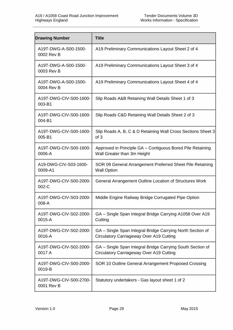
A19T-DWG-A-S00-1500-0002 Rev B
A19 Preliminary Communications Layout Sheet 2 of 4
A19T-DWG-A-S00-1500-0003 Rev B
A19 Preliminary Communications Layout Sheet 3 of 4
A19T-DWG-A-S00-1500-0004 Rev B
A19 Preliminary Communications Layout Sheet 4 of 4
A19T-DWG-CIV-S00-1600-003-B1
Slip Roads A&B Retaining Wall Details Sheet 1 of 3
A19T-DWG-CIV-S00-1600-004-B1
Slip Roads C&D Retaining Wall Details Sheet 2 of 3
A19T-DWG-CIV-S00-1600-005-B1
Slip Roads A, B, C & D Retaining Wall Cross Sections Sheet 3 of 3
A19T-DWG-CIV-S00-1600-0006-A
Approved in Principle GA – Contiguous Bored Pile Retaining Wall Greater than 3m Height
A19-DWG-CIV-S03-1600-0009-A1
SOR 09 General Arrangement Preferred Sheet Pile Retaining Wall Option
A19T-DWG-CIV-S00-2000-002-C
General Arrangement Outline Location of Structures Work
A19T-DWG-CIV-S03-2000-008-A
Middle Engine Railway Bridge Corrugated Pipe Option
A19T-DWG-CIV-S02-2000-0015-A
GA – Single Span Integral Bridge Carrying A1058 Over A19 Cutting
A19T-DWG-CIV-S02-2000-0016-A
GA – Single Span Integral Bridge Carrying North Section of Circulatory Carriageway Over A19 Cutting
A19T-DWG-CIV-S02-2000-0017 A
GA – Single Span Integral Bridge Carrying South Section of Circulatory Carriageway Over A19 Cutting
A19T-DWG-CIV-S00-2000-0019-B
SOR 10 Outline General Arrangement Proposed Crossing
A19T-DWG-CIV-S00-2700-0001 Rev B
Statutory undertakers - Gas layout sheet 1 of 2

A19 / A1058 Coast Road Junction Improvement Tender Documents Volume 3D Highways England Works Information - Specification
Version 1.0 Page 30 May 2015
Drawing Number Title
A19T-DWG-CIV-S00-2700-0002 Rev B
Statutory undertakers - Gas layout sheet 2 of 2
A19T-DWG-CIV-S00-2700-0003 Rev B
Statutory undertakers - Water layout sheet 1 of 3
A19T-DWG-CIV-S00-2700-0004 Rev B
Statutory undertakers - Water layout sheet 2 of 3
A19T-DWG-CIV-S00-2700-0006 Rev B
Statutory undertakers - Electric layout
A19T-DWG-CIV-S00-2700-0007 Rev B
Statutory undertakers - BT layout
A19T-DWG-CIV-S00-3000-0001 Rev B
A19 Preliminary Landscape Design Sheet 1 of 4
A19T-DWG-CIV-S00-3000-0002 Rev B
A19 Preliminary Landscape Design Sheet 2 of 4
A19T-DWG-CIV-S00-3000-0003 Rev B
A19 Preliminary Landscape Design Sheet 3 of 4
A19T-DWG-CIV-S00-3000-0004 Rev B
A19 Preliminary Landscape Design Sheet 4 of 4

A19 / A1058 Coast Road Junction Improvement Tender Documents Volume 3D Highways England Works Information - Specification
Version 1.0 Page 31 May 2015
1 Standard Drawings 2(i) Supplied to Each Tenderer
Drawing Number Title Volume Number
2(ii) Inspected by Tenderers WSP UK,
Three White Rose Office Park,
Millshaw Park Lane, Leeds,
West Yorkshire
LS11 0DL
between the following dates: 18th May 2015 to 22nd May 2015 inclusive
and at the following times: 10am until 4pm
One copy will be supplied to the Contractor.
Drawing Number Title Aspect required if not whole Drawing
A19T-DWG-CIV-S00-0000-0001 Rev B
Geodetic Survey - General Arrangement Drawing Sheet 1 of 2
A19T-DWG-CIV-S00-0000-0002 Rev B
Geodetic Survey - General Arrangement Drawing Sheet 2 of 2
A19T-DWG-CIV-S00-0000-0003 Rev A
Highway Authority Allocation Drawing Sheet 1 of 2
A19T-DWG-CIV-S00-0000-0004 Rev A
Highway Authority Allocation Drawing Sheet 2 of 2
A19T-DWG-CIV-S00-0000-0009 Rev A
Statutory Undertakers Information C2 Engineering
A19T-DWG-CIV-S00-0000-0010 Rev A
Statutory Undertakers Information for C3 Sheet 1 of 6

A19 / A1058 Coast Road Junction Improvement Tender Documents Volume 3D Highways England Works Information - Specification
Version 1.0 Page 32 May 2015
Drawing Number Title Aspect required if not whole Drawing
A19T-DWG-CIV-S00-0000-0011 Rev A
Statutory Undertakers Information for C3 Sheet 2 of 6
A19T-DWG-CIV-S00-0000-0012 Rev A
Statutory Undertakers Information for C3 Sheet 3 of 6
A19T-DWG-CIV-S00-0000-0013 Rev A
Statutory Undertakers Information for C3 Sheet 4 of 6
A19T-DWG-CIV-S00-0000-0014 Rev A
Statutory Undertakers Information for C3 Sheet 5 of 6
A19T-DWG-CIV-S00-0000-0015 Rev A
Statutory Undertakers Information for C3 Sheet 6 of 6
A19T-DWG-CIV-S00-0100-0044 Rev A
Drainage Departure Location Plan
A19T-DWG-CIV-S00-0100-0045 Rev A
Silverlink Roundabout Proposed Layout
A19T-DWG-CIV-S00-0100-0052 Rev A
A19 Long section – Mainline and Southbound Slip roads (MC9Z)
2(iii) Brought into the Contract by Reference HCD published by The Stationery Office as Volume 3 of the Manual of Contract Documents for Highway Works contains the following drawings brought into the Contract by reference. Unless otherwise stated below the whole drawing is brought into the Contract.
Drawing Number Title Date Aspect required if not whole Drawing
F1 Surface Water Drains – Trench and Bedding Details
December 1991
F2 Filter Drains – Trench and Bedding Details
November 2003
F3 Type 1 Chamber (Brick or in-situ Concrete Manhole)
May 2006
F4 Type 2 Chamber (Precast Concrete Manhole)
May 2006

A19 / A1058 Coast Road Junction Improvement Tender Documents Volume 3D Highways England Works Information - Specification
Version 1.0 Page 33 May 2015
Drawing Number Title Date Aspect required if not whole Drawing
F5 Type 3 Chamber (Precast Concrete Manhole)
May 2006
F6 Type 4 Chamber (Precast Concrete Manhole)
May 2006
F11 Type 7 Chamber (1050 Catchpit)
May 2006
F12 Type 8 Chamber (600 Catchpit)
May 2006
F13 Precast and In-Situ Cast Gullies
May 2006
F18 Edge of Pavement Drains - Fin Drains and Narrow Filter Drains
December 1991
F19 Edge of Pavement Drains – Installation of Fin Drains
December 1991
F20 Edge of Pavement Drains – Installation of Narrow Filter Drains
December 1991
H1 Temporary Fences Types 1 and 2
May 2004
H2 Temporary Fences Types 3 and 4
May 2004
H3 Motorway and Accommodation Works Timber Post and 4 (or 5) Rail Fences
May 2004
H7 Turning Posts Strained Wire Fences
December 1991
H36 Diagrammatic Methods of Attaching Fencing to Structures
November 2006
I1 Longitudinal Sections and Details of Transverse Ducts
May 2004 Marker Block
K1 Road Lighting Columns – Fastener Head in Door Recess and Key
December 1991
A19 / A1058 Coast Road Junction Improvement Tender Documents Volume 3D Highways England Works Information - Specification
Version 1.0 Page 34 May 2015
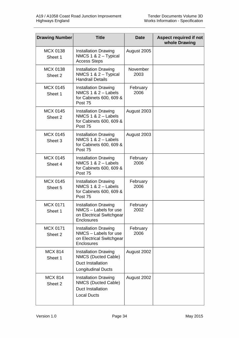
Drawing Number Title Date Aspect required if not whole Drawing
MCX 0138 Sheet 1
Installation Drawing NMCS 1 & 2 – Typical Access Steps
August 2005
MCX 0138 Sheet 2
Installation Drawing NMCS 1 & 2 – Typical Handrail Details
November 2003
MCX 0145 Sheet 1
Installation Drawing NMCS 1 & 2 – Labels for Cabinets 600, 609 & Post 75
February 2006
MCX 0145 Sheet 2
Installation Drawing NMCS 1 & 2 – Labels for Cabinets 600, 609 & Post 75
August 2003
MCX 0145 Sheet 3
Installation Drawing NMCS 1 & 2 – Labels for Cabinets 600, 609 & Post 75
August 2003
MCX 0145 Sheet 4
Installation Drawing NMCS 1 & 2 – Labels for Cabinets 600, 609 & Post 75
February 2006
MCX 0145 Sheet 5
Installation Drawing NMCS 1 & 2 – Labels for Cabinets 600, 609 & Post 75
February 2006
MCX 0171 Sheet 1
Installation Drawing NMCS – Labels for use on Electrical Switchgear Enclosures
February 2002
MCX 0171 Sheet 2
Installation Drawing NMCS – Labels for use on Electrical Switchgear Enclosures
February 2006
MCX 814 Sheet 1
Installation Drawing NMCS (Ducted Cable) Duct Installation Longitudinal Ducts
August 2002
MCX 814 Sheet 2
Installation Drawing NMCS (Ducted Cable) Duct Installation Local Ducts
August 2002

A19 / A1058 Coast Road Junction Improvement Tender Documents Volume 3D Highways England Works Information - Specification
Version 1.0 Page 35 May 2015
Drawing Number Title Date Aspect required if not whole Drawing
MCX 814 Sheet 3
Installation Drawing NMCS (Ducted Cable) Duct Installation Transverse Ducts
November 2003
MCX 814 Sheet 4
Installation Drawing NMCS (Ducted Cable) Duct Installation Spacer and Strapping
August 2002
MCX 815 Sheet 3
Installation Drawing NMCS (Ducted Cable) Chambers Type B
August 2004

A19 / A1058 Coast Road Junction Improvement Tender Documents Volume 3D Highways England Works Information - Specification
Version 1.0 Page 36 May 2015
APPENDIX 1/1: TEMPORARY ACCOMMODATION AND EQUIPMENT FOR THE OVERSEEING ORGANISATION
1 Accommodation Required It has been agreed that Plot 2/4a as detailed on Land Plan Sheet 2 (A19T-DWG-CIV-S00-0000-0068 Rev D) shall be used as the Contractor’s Site Compound for the A19 / A1058 Coast Road Junction Improvement Scheme. It is envisaged that there will be a total of 22 staff on site from the Overseeing Organisation, Site Supervisor and Design Consultant. The site accommodation shall be shared by all organisations.
1.1 Principal Office 1.1.1 The layout of the Principal Offices shall be as agreed by the Project Manager
and shall be shared accommodation with the Contractor.
1.1.2 The accommodation shall include a joint entrance and reception area with receptionist, and shared messing facilities, car parking and security arrangements.
1.1.3 The Principal Offices shall be newly executed, weatherproof, vermin proof and newly decorated internally.
1.1.4 No advertisements or company names shall be displayed.
1.1.5 During the currency of the Contract, the Contractor shall supply and maintain all fuel including all fuel associated with Vehicles for the Overseeing Organisation, water, heating, light, attendance, security, phone connections including payment of all phone bills.
1.1.6 The Principal Office shall be served by an access road at least 6 m wide and have a hard standing for use as a car park adjacent and within view.
1.1.7 The Principal Office compound shall be properly drained with paved or flagged steps and galvanised steel handrails provided at all entrances and emergency exits.
1.1.8 Roads and hard standings shall comprise 100 mm thickness of dense bitumen macadam to Clause 906 on not less than 200 mm thickness of sub-base to Clause 803 of the Specification for Highways Works.
1.1.9 Access to and from the public roads shall be executed to the requirements of the relevant highway authority.
1.1.10 The Contractor shall provide an electrical supply to the Principal Office which shall be wired and earthed in accordance with the requirements of Northern Powergrid.
1.1.11 An adequate supply of chilled potable water shall be provided to the Principal Office.
1.1.12 The Contractor shall supply sanitary facilities for the shared use of the staff of the Project Manager and the Contractor.
1.1.13 A water supply shall be provided to the Principal Offices with clean running hot and cold water and all pipes and tanks to be adequately lagged. An external water supply tap in the vicinity of the rear access doors to the office shall be provided.

A19 / A1058 Coast Road Junction Improvement Tender Documents Volume 3D Highways England Works Information - Specification
Version 1.0 Page 37 May 2015
1.1.14 Toilets shall be in the Principal Office. Each toilet shall be connected to the foul drainage system and to a water supply for flushing. Chemical toilets will not be permitted. Wash basins and sinks shall be supplied with clean running hot and cold water, soap and clean towels. Warm air hand dryers shall be provided.
1.1.15 Waste connections shall be made to the local sewer system or septic tank in accordance with Environmental Agency guidelines and to the approval of the local authority. The Contractor shall service this system during the full period of the Contract including the Defects Period.
1.1.16 On Substantial Completion of the Works, the Contractor shall restore all ground levels including backfilling of any sewerage treatment system.
1.1.17 The Contractor shall insure the contents of all offices, including goods and chattels belonging to:
(i) the Overseeing Organisation
(ii) the Project Manager and
(iii) the Project Manager’s Personnel
against fire, burglary, theft and other risks ordinarily insured against.
Minimum amount of cover as follows:
£15,000 for any one incident with no limit on number of incidents.
2 Duration of Time Accommodation Required 2.1 All accommodation complete with fittings and contents, shall be ready for
occupation and use by the Overseeing Organisation from one week prior to the commencement of the Works until eight weeks after the issue and acceptance of the Construction Certificate.
3 Fittings and Furnishings of Accommodation, and other Equipment Required
3.1 Lighting and Heating 3.1.1 The minimum level of artificial illumination shall be 400 lux with lighting
provided in all rooms and corridors. A minimum window area of 20% is required in all rooms excluding toilets and corridors. Windows shall open to provide adequate ventilation.
3.1.2 The principal offices shall have electric heaters with room thermostats capable of maintaining a minimum room temperature of 21°C. All heaters shall be fitted with timer units. In the event of power failures, the Contractor shall provide an alternative means of power supply (e.g. portable generators) within 2 hours.

A19 / A1058 Coast Road Junction Improvement Tender Documents Volume 3D Highways England Works Information - Specification
Version 1.0 Page 38 May 2015
Office units shall have a minimum standard of thermal insulation to the following levels:
Floor 0.39 W/m2K
External Walls 0.43 W/m2K
Roof 0.45 W/m2K
3.2 Cleaning and Laundry 3.2.1 The principal offices shall be cleaned by a dedicated cleaner once per Site
working day (excluding Saturdays, Sundays and Bank Holidays). Cleaning shall include for the disposal of all waste including surface water and foul sewage to the requirements of the Local Authority.
3.2.2 The car park area shall be thoroughly cleaned weekly.
3.2.3 Laundering of tea towels shall be carried out on a weekly basis.
3.2.4 The main cleaning and services shall be carried out outside normal Site working hours.
3.3 General 3.3.1 The Principal Office shall comply in all respects with the provisions of the
Building Regulations 2010; the Health, Safety and Welfare at Work (Construction) Regulations 2013 and any other relevant legislation.
3.3.2 Blinds and mesh guards shall be provided at all external windows.
3.3.3 Floor coverings shall be heavy-duty linoleum.
3.3.4 A smoke detection system shall be provided in all offices and corridors.
3.3.5 Each office, store and toilet shall be equipped with a fire extinguisher. In addition, one fire extinguisher shall be located in the Principal compound car park, clearly marked “Fire Safety Point”.
3.3.6 Doors shall be signed as directed.
3.3.7 An adequate supply of electrical sockets shall be provided. Extension leads and adapters shall be supplied on request.
3.3.8 All doors shall be fitted with 5 lever locks supplied complete with 4 keys for external doors and 2 keys for internal doors.
3.4 Security 3.4.1 For the security of the Principal Office, the Contractor shall provide
(i) a galvanised steel palisade fence 2.4 m high with steel posts at 2.75 metre centres and corrugated pales with triad heads
(ii) the entrance gate shall be in two sections, each 3.0 m wide by 2.4 m high with crossbolt, slapping plate and lugs for hanging, all neatly welded together with a hot dip galvanised finish to BS1722
(iii) an automatic fire and alarm system within the Principal Office, consisting of movement detectors to cover all corridors, the General Office area and the Project Managers Office. Heat and smoke sensors shall be installed in the offices of the Overseeing

A19 / A1058 Coast Road Junction Improvement Tender Documents Volume 3D Highways England Works Information - Specification
Version 1.0 Page 39 May 2015
Organisation, the Assistant Project Managers, the kitchen and the General Office
(iv) a 500-watt external security light, waterproofed and fitted with grills, one attached to each façade, which shall be switched from a central position and shall be controlled using a 24 hour, 7 day timer and
(v) the Contractor shall supply manned security at the Principal Office out of the Site working hours detailed in Appendix 1/7 of the Specification. The security personnel shall maintain records of all access taken outside of the Site working hours.
3.5 Schedule of Furnishings and Fittings 3.5.1 The Contractor shall be responsible for the cleaning and maintenance of all
equipment and instruments including the payment of all charges in connection with maintenance and repair in accordance with the maker's specification. The Contractor shall promptly replace unsatisfactory, unserviceable or damaged items. All equipment shall be supplied with plugs or batteries as appropriate. Items marked * are to be retained by the Overseeing Organisation.
3.5.2 Principal Offices
22 Number Single pedestal desk. Minimum working top size shall be 1.8 m x 0.75 m. Desk shall have integral cable management system and support shall be I frame complete with modesty panel. Desk legs shall be adjustable.
22 Number Chair with arm rest, lumbar support.
5 Number Cupboard, 2.0 m high by 1.0 m wide by 0.5 m deep with 4 Number shelves. Lockable
5 Number 3 square metre Dry marker notice board wall mounted
22 Number Telephone extension
22 Number 4 – tier “beanstalk” letter tray with base
22 Number Wastepaper bin
3.5.2 Equipment
Item External telephone line with 22 handsets incorporating call forward and call pick-up facilities
Item Internet connection capable of serving the computers listed below minimum 16Mbps download speed including all necessary hardware
5 Number 20.0 megapixel digital compact camera, complete with software, PC link, with 5 Number 4 gigabyte SDHC memory cards and carrying case

A19 / A1058 Coast Road Junction Improvement Tender Documents Volume 3D Highways England Works Information - Specification
Version 1.0 Page 40 May 2015
1 Number Maximum and Minimum Thermometer
2 Number Stainless steel straight edge, 1.5m long
3.5.3 Kitchen Facilities (shared facilities with Contractor) to have a minimum of:
1 Number Domestic cooker with 4 rings, grill and oven compartment
1 Number Domestic fridge freezer, 3* freezer
1 Number 2-litre capacity electric kettle
1 Number 4 slice electric toaster
1 Number Microwave oven. Turntable type, 1000 Watt
1 Number Dishwasher
1 Number Hood and extractor fan to cooker
1 Number Heavy duty domestic vacuum cleaner
1 Number 3 square metre Notice board wall mounted
1 Number Work top (15 linear m) with kitchen units incorporating sink and cupboards for food and kitchen consumables storage (see below)
1 Number Sink unit with double drainer plumbed for hot and cold running water and connected to the foul water system
3 Number Under sink cupboards for kitchen consumables
4 Number Food storage cupboards
4 Number Saucepans, various sizes
2 Number Carrying Tray (300 by 600 mm)
1 Number Swing top bins
1 Number Fire Blanket.
Item Supply of clean tea towels and hand towels
Item Sufficient Mugs, cutlery (knife, fork, dessert spoon & teaspoon) for the number of persons using the kitchen
3.5.4 The Contractor shall provide a suitably furnished conference room that shall accommodate a minimum of 20 occupants.

A19 / A1058 Coast Road Junction Improvement Tender Documents Volume 3D Highways England Works Information - Specification
Version 1.0 Page 41 May 2015
3.6 Computer Equipment 3.6.1 Computer equipment to be networked and retained by the Overseeing
Organisation until 3 months after the issue of the Construction Certificate.
3.6.2 The Contractor shall supply, install and maintain individual pc / laptop computer equipment for 16 staff, indicative specification as follows:
Processor Windows 7 64 bit Intel® Core™ i7 processor
Memory 32GB RAM -
Monitor Minimum 17” Colour Flat Panel Monitors.
Hard Disk 256GB Solid State Drive
Graphics nVidia Quadro K2100M Graphics
The Contractor shall supply, install and maintain individual pc / laptop computer equipment for 6 staff, indicative specification as follows
Processor Intel Xeon E5-1620V2 / 3.7 GHz
Memory 32GB RAM
Monitor 24 Inch Widescreen TFT Monitor
Hard Disk 1TB Hard Drive
Graphics Graphics: nVidia Quadro K4000 Graphics
Software Windows 8.1 Pro64
MS Office 2013 Professional on all machines
AutoCAD (Current version) on a minimum of six machines
Adobe Acrobat XI Professional on a minimum of two machines
Bentley MX 2013 including annual support package on one machine
Virus Protection Software
3.6.3 The following printers / photocopiers shall be made available to the Overseeing Organisation and maintained by the Contractor:
1 Number Colour printer/scanner capable of printing A3 and A4 sheets, min 11 ppm black & white, min 7.5 ppm colour (shared with Contractor). Not less than 1200 x 600dpi, USB (or parallel) interface and all necessary software and drivers. Ink cartridges for the printer are to be considered consumable and to be supplied as required.

A19 / A1058 Coast Road Junction Improvement Tender Documents Volume 3D Highways England Works Information - Specification
Version 1.0 Page 42 May 2015
1 Number Colour plotter capable of printing A0 sheets, min 1 x A1 ppm colour (shared with Contractor). Not less than 2400 dpi, USB (or parallel) interface and all necessary software and drivers. Ink cartridges for the printer are to be considered consumable and to be supplied as required.
3.6.4 All equipment shall be installed and commissioned by a reputable Quality Assured supplier (ISO 9000 or equivalent) who has resources available in the region for repair or replacement.
3.6.5 The equipment, network and system management software shall be supported by a proactive maintenance contract with an 8 hour maximum response time up to the end of the Defects Period above. It shall include regular Site visits to proactively update systems and ensure adequate protection and pre-empt any problems.
3.7 Publications 3.7.1 The Contractor shall supply the following publications for the sole use of the
Overseeing Organisation:
1 Set NEC Engineering and Construction Contract (Third Edition)
1 Set Traffic Signs Manual Chapter 8
1 No. Traffic Signs Regulations and General Directions, 2002
3.8 Surveying Equipment 3.8.1 The Contractor shall afford the Overseeing Organisation the use of any
survey equipment available on Site as required by the Project Manager.
3.9 Personal Protective equipment 3.9.1 The Contractor shall provide the Overseeing Organisation with office
consumables as required by the Project Manager.
3.9.2 Sets of the following shall be supplied new for use by the Overseeing Organisation’s in various sizes as and when required by the Project Manager:
i. Band and Brace Hi-Visibility long sleeved jacket in high conspicuity yellow to EN 471:2003 Class 3.
ii. Band and Brace Hi-Visibility weather-proof jacket and over trousers, with detachable linings or thermal jackets in high conspicuity yellow to EN 471:2003 Class 3.
iii. Saturn Yellow Waterproof Coverall to EN343:2003.
iv. Pair of safety wellingtons with steel toe cap and sole, to BS1870 Part 2.
v. Pair of safety boots with steel toe cap and sole to BS 1870 Part 1.
vi. Boot stockings.
vii. Pair of heavy duty rigger gloves.

A19 / A1058 Coast Road Junction Improvement Tender Documents Volume 3D Highways England Works Information - Specification
Version 1.0 Page 43 May 2015
viii. Safety helmet to BS 5240, coloured white with integrated eyewear approved to grade B medium energy impact.
ix. Safety helmet to BS 5240, (marked “Visitors”), coloured yellow.
x. Safety glasses approved to CE EN 166 for medium energy impact.
xi. Pairs of passive ear defenders to suit safety helmets provided above.
3.10 Miscellaneous 3.10.1 The Contractor shall provide the Overseeing Organisation with office
consumables as required by the Project Manager.
2 No. Pair of manhole keys, minimum 500mm long
2 No. Rechargeable inspection safety hand lamps with charger unit
50m and 8m steel measuring tapes as required
Waterproof marking crayons as required
Road marking aerosols (yellow) as required
3.11 Consumables 3.11.1 The Contractor shall provide the Overseeing Organisation with consumables
including but not limited to stationery, writing instruments, kitchen and bathroom supplies. All shall be supplied on request and shall be replenished as necessary until eight weeks after the issue and acceptance of the Construction Certificate or such earlier date as shall be notified in writing by the Project Manager.

A19 / A1058 Coast Road Junction Improvement Tender Documents Volume 3D Highways England Works Information - Specification
Version 1.0 Page 44 May 2015
APPENDIX 1/2: VEHICLES FOR THE OVERSEEING ORGANISATION
Type Number Required
Period Required Cleaning Frequency
A 1 For the duration of the construction of the underpass Works
Weekly
B 0 - -
C 3 Until 3 months after Substantial Completion of the Works
Weekly
D 0 - -
1 Equipment 1.1 Vehicles shall be new and previously unused.
1.2 The vehicles shall be fitted with fire extinguisher, first aid kit, heater and demister, detachable hazard flashing unit with bulbs, heavy duty suspension, spare wheel, tow bar, fuel filler cap lock, bonnet lock and spare wheel lock, internal and external mirrors, mud flaps, floor mats front and rear, interior sun visors, gearbox covers, tow rope, towing hooks front and rear, laminated windscreen and guards for side, tail, stop and flasher lamps.
1.3 Driver and passenger full size airbag with side impact protection/airbags, air conditioning and full remote controlled central locking system/alarm/immobiliser shall be fitted.
1.4 Vehicles shall be provided for the exclusive use of the Overseeing Organisation at all times for whatever purpose the Overseeing Organisation so requires.
1.5 The Contractor shall indemnify the Overseeing Organisation, his representatives and their respective staff authorised to drive the vehicles against any claim in respect of damage to vehicles including claims from passengers.
2 Type “A” SUV/Off-road Vehicle 2.1 Maximum emissions 255g/Km.
2.2 Minimum carrying capacity of 2 people.
2.3 Minimum ground clearance of 200mm.
2.4 The vehicle is to be suitable for off-road use and public highway use, have 4 wheel drive, power steering, heavy duty suspension and be supplied in a conspicuous colour.

A19 / A1058 Coast Road Junction Improvement Tender Documents Volume 3D Highways England Works Information - Specification
Version 1.0 Page 45 May 2015
3 Type “B” 4 Door Estate Car 3.1 Maximum emissions 130g/Km.
3.2 Minimum carrying capacity of 5 people.
4 Type “C” Car 4.1 Maximum emissions 130g/Km.
4.2 Minimum carrying capacity of 5 people.
5 Type “D” Other Vehicle 5.1 Maximum emissions 130g/Km.
5.2 Minimum carrying capacity of 5 people.
6 Markings 6.1 The vehicles shall be free from markings identifying any company
associated with the Contract or the Contractor.

A19 / A1058 Coast Road Junction Improvement Tender Documents Volume 3D Highways England Works Information - Specification
Version 1.0 Page 46 May 2015
APPENDIX 1/3: RADIO COMMUNICATION SYSTEM FOR THE OVERSEEING ORGANISATION
1 Mobile Phones 1.1 The Contractor shall supply, install and maintain 10 Number digital mobile
telephones, Nokia 108 or equivalent, complete with connection to the Vodafone network, or equivalent, for the exclusive use of the Overseeing Organisation and his staff to the end of the Defects Period (excluding the landscape Works).
1.2 The SIM cards shall be new and the phone numbers not used before.
1.3 Each mobile telephone shall be provided with a battery charger.
1.4 The Contractor shall pay all monthly standing and call charges for the digital mobile telephones.

A19 / A1058 Coast Road Junction Improvement Tender Documents Volume 3D Highways England Works Information - Specification
Version 1.0 Page 47 May 2015
APPENDIX 1/4: WORKING AND FABRICATION DRAWINGS 1. The Contractor shall provide working and fabrication drawings for the Works
described in Table 1/4.1 and for all structural steel work at the following locations:
(i) Silverlink A1058 Eastbound Off Slip Footbridge.
(ii) Silverlink A1058 Eastbound On Slip Footbridge.
Table 1/4.1: Working and Fabrication Drawing Requirements
Series Description of Work Minimum period for submission of drawings
- Working drawings shall be supplied by the Contractor for all the elements of the Works designed by or on behalf of the Contractor
4 weeks prior to any such Works commencing
1800 Fabrication drawings shall be supplied by the Contractor for all items of Steelwork, even if fabrication is undertaken by computer controlled equipment
4 weeks prior to any such Works commencing

A19 / A1058 Coast Road Junction Improvement Tender Documents Volume 3D Highways England Works Information - Specification
Version 1.0 Page 48 May 2015
APPENDIX 1/5: TESTING TO BE CARRIED OUT BY THE CONTRACTOR
Notes:
1 Unless otherwise stated above, all sampling and testing in this Appendix shall be by the Contractor.
2 Tests comparable to those specified in this Appendix will be necessary for any equivalent work, goods or materials proposed by the Contractor.
3 (N) indicates that a UKAS or equivalent accredited laboratory sampling and test report or certificate is required.
4 Unless otherwise shown in this Appendix tests for work, goods or materials as scheduled under any one Clause are required for all such work, goods or materials in the Works.
5 Cube strength tests are not required for concrete complying with Clause 2602.
6 Unless otherwise shown in this Appendix test certificates for work, goods or materials as scheduled under any one Clause are required for all such work, goods or materials in the Works.
7 The minimum number of earthworks tests shall be 3 per source, before the source can be approved by the Project Manager for use. Where the volume of a single source used in the earthworks operation is in excess of 5,000m³, once 5,000m³ has been used the rate of testing may be reduced to 1 test per 1000m3 subject to approval by the Project Manager.
8 Frequency of testing applies to each separate earthworks material within each of the earthworks material class.
9 Unless specifically stated to the contrary, all samples used in the earthworks testing shall be taken from materials after delivery to the Site for incorporation into the Works.
10 The Contractors attention is drawn to the requirements of the relevant Specification Appendices for the form of all deliverables, storage of test records and storage of records of materials imported to / exported from Site.
11 Where source approval is specified, source testing shall be carried out at each quarry or stockpile used for supply to Site and at each location of borrow/Site winnings used for on-Site material.
12 Definitions of earthworks abbreviations:
MC: natural moisture content.
Organic Matter: Organic Matter Content as determined from the ‘Walkley Black Method.
OMC: Optimum Moisture Content.
MDD: Maximum Dry Density.
HSV: Hand Shear Vane.
ACM: Asbestos and Asbestos Containing Materials.
13 For chemical testing requirements refer to the relevant Appendix for class of material and the requirements of Appendix 6/14 and 6/15 of this Specification.

A19 / A1058 Coast Road Junction Improvement Tender Documents Volume 3D Highways England Works Information - Specification
Version 1.0 Page 49 May 2015
Table 1/5: Testing to be carried out by the Contractor
Clause Work, Goods or Material Test Frequency of Testing
Test Certificate
Comments
Series 300
306 Permanent fencing Quality management scheme applies
Concrete components Cover to reinforcement
1 per consignment (maximum 1 per 100 components) (BS 1722)
308 Gates and stiles Quality management scheme applies
Concrete components Cover to reinforcement
1 per consignment (maximum 1 per 100 components) (BS 3470)
308 & 311
Preservation of timber Full sapwood penetration
As required in sub-Clause 311.2(v)
Required for each batch
Quality management scheme applies
Series 400
402 Welding Welding procedures (Manufacturer’s tests)
(Every seven years)
Required Requirements here are applicable only to systems not falling under the Construction Products Regulation (CPR). Quality management scheme applies
Welder qualification (Manufacturer’s tests)
As required in sub-Clause 402.6(iii)
Production testing (Manufacturer’s tests)
As required in sub-Clause 402.6(iv)
Welded joints Destructive testing
See sub-Clauses 402.6(v) and 402.6(vi)
Wire rope terminals Tensile tests (Manufacturer’s tests)
Annually and when production technique changed
Required To provide evidence of tests by a testing laboratory Requirements here are applicable only to systems not falling under the CPR.
403 Anchorages and attachment systems for use in drilled holes
Ultimate tensile load (Manufacturer’s tests)
Required To provide well attested and documented evidence

A19 / A1058 Coast Road Junction Improvement Tender Documents Volume 3D Highways England Works Information - Specification
Version 1.0 Page 50 May 2015
Table 1/5: Testing to be carried out by the Contractor Continued
Clause Work, Goods or Material Test Frequency of Testing
Test Certificate
Comments
Series 400 (Continued)
404 Anchorages in drilled holes Loading test on Site
As required in contract specific Appendix 4/1
Required
Post foundations Required
406 Vehicle parapets Required Quality management scheme applies - applicable only to systems not falling under the CPR.
407 Anchorages and attachment systems for use in drilled holes
Ultimate tensile load (Manufacturer’s test)
Required To provide well attested and documented evidence for systems not falling under the CPR.
409 Vehicle parapet posts Production testing as specified in BS 6779-1 1998 (Amd No 14290, 21 March 2003) (Manufacturer’s tests)
Required Certification in accordance with Clause 409 is required for systems not falling under the CPR.
410 Anchorages in drilled holes On-Site tensile load test
As required in contract specific Appendix 4/1
Required
Series 500
501 Pipes for drainage and service ducts
Product certification scheme or equivalent applies for products not falling under the Construction Products Regulation (CPR).
Vitrified clay
Concrete PC/SRC
Not exceeding 900 mm dia
Concrete prestressed
Iron-cast
Iron-ductile
PVC-U
GRP
Plastics. See Table 5/1
Corrugated steel (Manufacturer’s tests)
Required (AASHTO)
Corrugated steel bitumen protection
Not exceeding 900 mm dia

A19 / A1058 Coast Road Junction Improvement Tender Documents Volume 3D Highways England Works Information - Specification
Version 1.0 Page 51 May 2015
Table 1/5: Testing to be carried out by the Contractor Continued
Clause Work, Goods or Material Test Frequency of Testing
Test Certificate
Comments
Series 500 (Continued)
501 Cont’d
Other materials Required Product Acceptance Scheme or equivalent applies
503 Pipe bedding Grading and fines content
1 per 500 tonnes (min of 3)
Water-soluble sulfate (WS) content (N)
1 per source
Oxidisable sulfides (OS) content and total potential sulfate (TPS) content (N)
Resistance to fragmentation (N)
505 Filter medium backfill Plastic index (N) 1 per source*
For bedding types not falling under the Construction Products Regulation (CPR), Results of routine control tests from the factory production control system operated by the producer to be provided - see BS EN 13285
Resistance to fragmentation (N)
1 per source*
Water-soluble sulfate (WS) content (N)
5 per source
Oxidisable sulfides (OS) content and total potential sulfate (TPS) content (N)
5 per source
Grading 1 per 500 tonnes*
For bedding types not falling under the Construction Products Regulation (CPR), Results of routine control tests from the factory production control system operated by the producer to be provided - see BS EN 13285
Permeability (N) 1 per source*
506 Sealing existing drains
Concrete

A19 / A1058 Coast Road Junction Improvement Tender Documents Volume 3D Highways England Works Information - Specification
Version 1.0 Page 52 May 2015
Table 1/5: Testing to be carried out by the Contractor Continued
Clause Work, Goods or Material Test Frequency of Testing
Test Certificate
Comments
Series 500 (Continued)
506 Cont’d
Grout
507 Chambers Product certification scheme or equivalent applies
Precast concrete
Corrugated galvanised steel
(Manufacturer’s tests)
Required Product certification scheme or equivalent applies Steel fitments
Covers, grates and frames
Product certification scheme or equivalent applies
Cover bolts Quality management scheme or equivalent applies
508 Gullies and pipe junction For products not falling under the (CPR) product certification scheme or equivalent applies
Precast concrete
Clay
Cast iron and steel
509 Watertightness of joints Air test All pipelines with watertight joints
Required
512 Backfill to pipe bays Grading 1 per 50 tonnes (min of 3)
Water-soluble sulfate (WS) content (N)
1 per source
Oxidisable sulfides (OS) content and total potential sulfate (TPS) content (N)
1 per source
513 Permeable backing to earth retaining structures
Plastic index (N)
Water-soluble sulfate (WS) content (N)
Oxidisable sulfides (OS) content and total potential sulfate (TPS) content (N)
Resistance to fragmentation (N)
Grading 1 per 200 tonnes (min of 3)

A19 / A1058 Coast Road Junction Improvement Tender Documents Volume 3D Highways England Works Information - Specification
Version 1.0 Page 53 May 2015
Table 1/5: Testing to be carried out by the Contractor Continued
Clause Work, Goods or Material Test Frequency of Testing
Test Certificate
Comments
Series 500 (Continued)
513 Cont’d
Permeability (N) 1 per source
Precast hollow concrete blocks
(Manufacturer’s tests)
Required
514 Fin drains (Manufacturer’s tests)
Required Product Acceptance Scheme or equivalent) applies
515 Narrow filter drains
Geotextile, pipes and fittings
(Manufacturer’s tests)
Required Product Acceptance Scheme or equivalent) applies
Granular fill Plastic index (N) 1 per source*
Resistance to fragmentation (N)
Water-soluble sulfate (WS) content (N)
5 per source
Oxidisable sulfides (OS) content and total potential sulfate (TPS) content (N)
5 per source
Grading 1 per 200 tonnes (min of 3)*
Permeability (N) 1 per source*
516 Combined drainage and kerb systems
Load test A minimum of 1 test and not less than 1 test per 1000m for each type and source
Required Certification that they systems comply with Clause 516 is required
517 Linear drainage systems Load test A minimum of 1 test and not less than 1 test per 1000m for each type and source
Required Certification that they systems comply with Clause 517 is required
518 Thermoplastics structured wall pipes and fittings
(Manufacturer’s tests)
Required Product Acceptance Scheme or equivalent applies
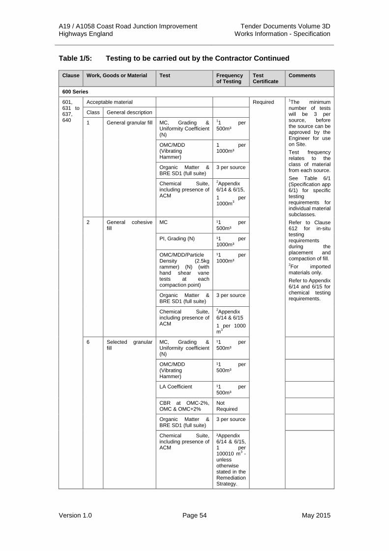
A19 / A1058 Coast Road Junction Improvement Tender Documents Volume 3D Highways England Works Information - Specification
Version 1.0 Page 54 May 2015
Table 1/5: Testing to be carried out by the Contractor Continued
Clause Work, Goods or Material Test Frequency of Testing
Test Certificate
Comments
600 Series
601, 631 to 637, 640
Acceptable material Required 1The minimum number of tests will be 3 per source, before the source can be approved by the Engineer for use on Site. Test frequency relates to the class of material from each source. See Table 6/1 (Specification app 6/1) for specific testing requirements for individual material subclasses. Refer to Clause 612 for in-situ testing requirements during the placement and compaction of fill. 2For imported materials only. Refer to Appendix 6/14 and 6/15 for chemical testing requirements.
Class General description
1 General granular fill MC, Grading & Uniformity Coefficient (N)
11 per 500m³
OMC/MDD (Vibrating Hammer)
1 per 1000m³
Organic Matter & BRE SD1 (full suite)
3 per source
Chemical Suite, including presence of ACM
2Appendix 6/14 & 6/15, 1 per 1000m3
2 General cohesive fill
MC ¹1 per 500m³
PI, Grading (N) ¹1 per 1000m³
OMC/MDD/Particle Density (2.5kg rammer) (N) (with hand shear vane tests at each compaction point)
¹1 per 1000m³
Organic Matter & BRE SD1 (full suite)
3 per source
Chemical Suite, including presence of ACM
2Appendix 6/14 & 6/15
1 per 1000 m3
6 Selected granular fill
MC, Grading & Uniformity coefficient (N)
¹1 per 500m³
OMC/MDD (Vibrating Hammer)
¹1 per 500m³
LA Coefficient ¹1 per 500m³
CBR at OMC-2%, OMC & OMC+2%
Not Required
Organic Matter & BRE SD1 (full suite)
3 per source
Chemical Suite, including presence of ACM
²Appendix 6/14 & 6/15, 1 per 100010 m3 -
unless otherwise stated in the Remediation Strategy.

A19 / A1058 Coast Road Junction Improvement Tender Documents Volume 3D Highways England Works Information - Specification
Version 1.0 Page 55 May 2015
Table 1/5: Testing to be carried out by the Contractor Continued
Clause Work, Goods or Material Test Frequency of Testing
Test Certificate
Comments
Series 600 (Continued)
601, 631 to 637, 640 Cont’d
7 Selected cohesive fill
MC (N) 1 per 500m³
Required ¹ The minimum number of tests will be 3 per source, before the source can be approved by the Engineer for use on Site. Test frequency relates to the class of material from each source. If multiple sources of the same class are used, each source shall be tested at the frequency stated in Appendix 1/5. See Table 6/1 (Specification app 6/1) for specific testing requirements for individual material subclasses. 2 For imported materials Refer to Clause 612 for in-situ testing requirements during the placement and compaction of fill. Refer to Appendix 6/14 and 6/15 for chemical testing requirements. Additional Chemical testing to be carried out in accordance with the Remediation Strategy
Grading 1 per 500m³
PL/LL (N) 1 per 500m³
OMC/MDD/Particle Density to include HSV at each compaction point (4.5kg Rammer)(N)
1 per 500m³
CBR remoulded at: OMC -2%, OMC & OMC+2%
Not required
Organic Matter & BRE SD1 (full suite)
3 per source, or 3 per 50,000m3 whichever is the greater number of tests.
Chemical Suite, including presence of ACM
²Appendix 6/14 & 6/15, 1 per 1000 m3
602 Earthworks material beneath the surface of a road or paved area, if within 450mm of finished surface
Frost Heave (N) Source Approval
Required For ALL material within 450mm finished level

A19 / A1058 Coast Road Junction Improvement Tender Documents Volume 3D Highways England Works Information - Specification
Version 1.0 Page 56 May 2015
Table 1/5: Testing to be carried out by the Contractor Continued
Clause Work, Goods or Material Test Frequency of Testing
Test Certificate
Comments
Series 600 (Continued)
612 Compaction of fills Required Compaction Trial to be completed in accordance with App 6/3. To be witnessed by Engineer.
Method compaction
Hand Shear Vane 1 per 50m x 50m grid per layer
Compaction Trial 1 per method per source.
End product compaction
Field Dry Density and HSV
1 per 250m3
Compaction Trial 1 per method per source.
Plate Load Test 0.6m Diameter (BS 1377 and DMRB IAN 73/06 Rev 1)
1 per 2500m2
every 4th layer, with a minimum of 1 test per 1m lift or part thereof.
Series 700
710 Constituent materials in recycled aggregate and recycled concrete aggregate
Quality control As required by the ‘Quality Protocol for the production of aggregates from inert waste’
Required
711 Overbanding and inlaid crack sealing systems
Required Product Acceptance Scheme or equivalent applies
Series 800
801, 803, 804, 805, 806
General Requirements for unbound mixtures for adjacent to cement bound materials, concrete pavements, structures or products
Water-soluble sulfate (WS) content (N)
1 per 400 tonnes or per location if less than 400 tonnes*
Required
Oxidisable sulfides (OS) content and total potential sulfate (TPS) content (N)
1 per 400 tonnes or per location if less than 400 tonnes*
Unbound mixtures beneath surface of a road or paved central reserve
Frost heave (N) 1 per source*
Grading and fines content
1 per week*
Plastic index (N)

A19 / A1058 Coast Road Junction Improvement Tender Documents Volume 3D Highways England Works Information - Specification
Version 1.0 Page 57 May 2015
Table 1/5: Testing to be carried out by the Contractor Continued
Clause Work, Goods or Material
Test Frequency of Testing
Test Certificate
Comments
Series 800 (Continued)
801, 803, 804, 805, 806 Cont’d
Unbound mixtures beneath surface of a road or paved central reserve Cont’d
Resistance to fragmentation (N)
6 monthly
Resistance to wear - micro-Deval test
Resistance to freezing and thawing (magnesium sulfate soundness) (N)
1 per source* Required
Water absorption (N)
Volume stability of blast furnace slags
6 monthly
Volume stability of steel (BOF and EAF) slags
6 monthly
CBR (N) 1 per source and then monthly*
OMC/mc (N)
Density (N)
Water absorption (N)
821, 822, 823, 830, 831, 832, 834, 835, 840
Cement and other Hydraulically Bound Mixtures (HBM)
Tests for control and checking of HBM
Tests specified in Table 8/14 and Table 8/15
Required
Coefficient of linear expansion
Tests for laboratory mixture design
Test specified in Clause 880
Series 900
901, 925, 937, 938, 943
Aggregates for bituminous materials
Required
Resistance to fragmentation (hardness)
Resistance to fragmentation (N)
Resistance to freezing and thawing (durability)
Soundness (N)
Water absorption (N)
Cleanness Sieve test (mass passing 0.063 mm sieve) (N)
Shape Flakiness index (N)
Blast furnace slag
Bulk density (N)
Soundness (N)

A19 / A1058 Coast Road Junction Improvement Tender Documents Volume 3D Highways England Works Information - Specification
Version 1.0 Page 58 May 2015
Table 1/5: Testing to be carried out by the Contractor Continued
Clause Work, Goods or Material
Test Frequency of Testing
Test Certificate
Comments
Series 900 (Continued)
901, 925, 937, 938, 943 Cont’d
Blast furnace slag Cont’d
Dicalcium silicate disintegration (N)
Required
Iron disintegration (N)
Steel slag Bulk density
Volume stability (N)
Coarse aggregate for surface courses
Resistance to polishing (PSV) (N)
Resistance to surface abrasion (AAV) (N)
Binders for bituminous materials
Penetration (N)
Softening point (N)
903 to 907, 909 to 912, 914, 916, 925, 926, 929, 930, 937, 938, 941, 943, 946 to 948
Bituminous mixtures Grading (N) For audit test purpose only
Binder content (N)
929 Base and Binder Course Asphalt Concrete (Design Mixtures)
Permanent Works - In situ air void content (N)
As required
Permanent Works - Refusal air void content (N)
Permanent Works - Deformation resistance
Deformation resistance (design)
As required
Stiffness (design)
930 EME2 Permanent Works - In situ air void content (N)
As required
Richness modulus (design)
As required
Duriez (design)
Deformation Resistance (design)
Stiffness (design)

A19 / A1058 Coast Road Junction Improvement Tender Documents Volume 3D Highways England Works Information - Specification
Version 1.0 Page 59 May 2015
Table 1/5: Testing to be carried out by the Contractor Continued
Clause Work, Goods or Material
Test Frequency of Testing
Test Certificate
Comments
Series 900 (Continued)
911 Rolled asphalt surface course (design mix)
Stability value (N)
Flow value (N)
Density (N)
915 Coated chippings Grading (N)
Binder content (N)
Flakiness index (N)
Resistance to polishing (PSV) (N)
Resistance to surface abrasion (AAV) (N)
Hot sand test (N)
Rate of spread (N)
921 Surface macro texture Volumetric Patch (N)
As required Required
924 High friction surfaces Quality control checks
As required in sub-Clause 924.5
Required Product Acceptance Scheme or equivalent applies System coverage As required in
sub-Clause 924.6
Aggregate Resistance to polishing (PSV) (N)
937 Stone mastic asphalt (SMA) binder course and regulating course
Permanent Works - In situ air void content (N)
As required
Permanent Works - Deformation resistance
Binder drainage test (design)
As required
Deformation resistance (design)
942 Thin surface course systems
General properties Required Product Acceptance Scheme or equivalent applies
943 Hot Rolled Asphalt surface course and binder course (performance-related design mixtures)
Permanent Works - In situ air void content (N)
As required
Permanent Works - Deformation resistance
Deformation resistance (design)
As required

A19 / A1058 Coast Road Junction Improvement Tender Documents Volume 3D Highways England Works Information - Specification
Version 1.0 Page 60 May 2015
Table 1/5: Testing to be carried out by the Contractor Continued
Clause Work, Goods or Material
Test Frequency of Testing
Test Certificate
Comments
Series 900 (Continued)
918 Slurry surfacing incorporating micro surfacing
Binder
Product Identification
Vialit cohesion
Rate of spread
Penetration at 25 ºC and 5 ºC (N)
Aggregates Flakiness index (N)
Resistance to polishing (AAV) (N)
Resistance to surface abrasion (AAV) (N)
Grading (N)
System
920 Bond coats, tack coats and other bituminous sprays
Binder Product identification
Vialit cohesion
Accuracy of spread
Rate of spread
Penetration at 25 ºC and 5 ºC (N)
919, 922 Surface dressing
Binder Product identification
Vialit cohesion
Accuracy of spread
Rate of spread
Penetration at 25 ºC and 5 ºC (N)
Chippings Resistance to (PSV) polishing (N)
Resistance to abrasion (AAV) (N)
Grading (N)

A19 / A1058 Coast Road Junction Improvement Tender Documents Volume 3D Highways England Works Information - Specification
Version 1.0 Page 61 May 2015
Table 1/5: Testing to be carried out by the Contractor Continued
Clause Work, Goods or Material
Test Frequency of Testing
Test Certificate
Comments
Series 900 (Continued)
919, 922 Cont’d
Chippings Binder content (N)
Flakiness index (N)
Accuracy of spread (N)
Rate of spread Frequency to be reduced to daily after 3 satisfactory results, but not less than 1 test per lane per Site
Rollers Spray bars working
Before work starts and daily during works
950 Depressions Product Acceptance Scheme or equivalent applies
Series 1100
#1101 Precast concrete kerbs, channels, edgings and quadrants
Bending strength
1102 In situ asphalt kerbs Grading 1 test per 500 m laid*
Required See BS 5931 for materials for in situ asphalt kerbs
Binder content
1104 Precast concrete flags Bending
Bedding Granular material
Mortar
1107 Concrete block paving Compressive strength
1108 Clay pavers Bending strength
Skid resistance

A19 / A1058 Coast Road Junction Improvement Tender Documents Volume 3D Highways England Works Information - Specification
Version 1.0 Page 62 May 2015
Table 1/5: Testing to be carried out by the Contractor Continued
Clause Work, Goods or Material Test Frequency of Testing
Test Certificate
Comments
Series 1200
1202 Permanent traffic signs
1207 Anchorage in drilled holes to supports of traffic signs
Loading test on Site
1210 Holding down bolts and anchorages to bases of permanent bollards
1212 Road Markings
1214 Permanent traffic cones and traffic cylinders
Required Certification that permanent traffic cones and cylinders have been tested and comply with BS EN 13422 is required
Flat traffic delineators Required
Tests specified in Clause 1214
As required
Other traffic delineators Required
Tests specified in contract specific Appendix 12/4
As required
Temporary cones, cylinders, FTD’s and other delineators
Required Certification that at least 1 in 500 of any batch of cones, cylinders, FTD’s and other delineators to be used in the Temporary Works have passed the tests in Clause 1214 as appropriate is required

A19 / A1058 Coast Road Junction Improvement Tender Documents Volume 3D Highways England Works Information - Specification
Version 1.0 Page 63 May 2015
Table 1/5: Testing to be carried out by the Contractor Continued
Clause Work, Goods or Material Test Frequency of Testing
Test Certificate
Comments
Series 1200 (Continued)
1217 Traffic signals Statutory type approval of equipment applies
Cables Product certification scheme or equivalent applies
Controllers Test specified in Appendix 12/5
Each controller before delivery to Site and again after installation
Cabling Tests a, b, c, e, f, g, h, j as defined in sub-Clause 1424.2
Each traffic signals installation
Required Certification that the installation complies with BS7671 (the IEE Wiring Regulations) is required
1218 Detector loops
Cable Required Certification that completed cables comply with specification TR 2029 is required
Epoxy resin Required Certification that the epoxy resin complies with specification MCH 1540 is required

A19 / A1058 Coast Road Junction Improvement Tender Documents Volume 3D Highways England Works Information - Specification
Version 1.0 Page 64 May 2015
Table 1/5: Testing to be carried out by the Contractor Continued
Clause Work, Goods or Material Test Frequency of Testing
Test Certificate
Comments
Series 1200 (Continued)
1218 Cont’d
Feeder cable Required Certification that completed cables comply with specification TR 2031 is required
Joints Pull test (4 kgf) Each crimp
Installation Series resistance Each loop Required Certification in accordance with specification MCH 1540 is required
Insulation resistance
Inductance
Series 1300
1305 Anchorages for use in drilled holes
Tensile load
1306 Anchorages in drilled holes to columns and masts with flange plates
Loading test on Site
As required
1313 GFRP laminates Loss on ignition 1 per 50 production columns
Colour fastness 1 per batch
Elastic strength
Water absorption
Impact strength
1314 Brackets for laminated GFRP lighting columns
Required
Polyurethane foam
Bulk density 1 per batch
Surface hardness
Apparent bulk density
2 per batch
Impact strength
Flexural stress
Series 1400
1421 Cable Product certification scheme or equivalent applies

A19 / A1058 Coast Road Junction Improvement Tender Documents Volume 3D Highways England Works Information - Specification
Version 1.0 Page 65 May 2015
Table 1/5: Testing to be carried out by the Contractor Continued
Clause Work, Goods or Material Test Frequency of Testing
Test Certificate
Comments
Series 1400 (Continued)
1424 Lighting units Tests specified in Clause 1424
Each unit Required Product certification scheme or equivalent applies Certification that the installation complies with BS7671 (the IEE Wiring Regulations) is required
Networks Tests specified in Clause 1424
Each network Required Certification that the installation complies with BS7671 (the IEE Wiring Regulations) is required
Series 1500
1506 Copper communications cable
Required Certification that each completed cable complies with specification TR 2150 or TR 2158, as appropriate, is required
Optical fibre communications cable
Required Certification that each completed cable complies with specification TR 2151 or TR 2159, as appropriate, is required
Coaxial communications Certification that each completed cable complies with specification TR 2152 or TR 2160, as appropriate, is required

A19 / A1058 Coast Road Junction Improvement Tender Documents Volume 3D Highways England Works Information - Specification
Version 1.0 Page 66 May 2015
Table 1/5: Testing to be carried out by the Contractor Continued
Clause Work, Goods or Material Test Frequency of Testing
Test Certificate
Comments
Series 1500 (Continued)
1506 Cont’d Energy cable Required Certification that each completed cable complies with specification TR 2153 or TR 2161, as appropriate, is required
1513 Cable joint enclosures Test specified in Clause 1513.12
Each CJE Required Certification that the CJE satisfies the air pressure test is required
1518 Coaxial and copper communications and power cable
Tests specified in specification MCG 1022 or MCG 1099, as appropriate
Each cable (Stage 1) As required in contract specific Appendix 15/1 (Stage 2)
Results to be reported in accordance with MCG 1022 or MCG 1099, as appropriate
Optical fibre communications cable
Tests specified in specification MCG 1055 or MCG 1099, as appropriate
Each cable (Stage 1) As required in contract specific Appendix 15/1 (Stage 2)
Results to be reported in accordance with MCG 1055 or MCG 1099, as appropriate
1522 Motorwarn System
Steel posts Required (BS 6323)
1526 Electrical Installations Tests specified in BS 7671
Each installation
Required Certification that the installation complies with BS 7671 (the IEE Wiring Regulations) is required.
1530 Cable ducts Product Acceptance Scheme or equivalent applies
1533 Cable ducts
Mandrel test Test specified in Clause 1533
Each duct Required Certificate that each length of duct between chambers satisfies the mandrel test is required.

A19 / A1058 Coast Road Junction Improvement Tender Documents Volume 3D Highways England Works Information - Specification
Version 1.0 Page 67 May 2015
Table 1/5: Testing to be carried out by the Contractor Continued
Clause Work, Goods or Material Test Frequency of Testing
Test Certificate
Comments
Series 1500 (Continued)
1533 Cont’d Air test Test specified in Clause 1533
Each duct Required Certificate that each length of duct between chambers satisfies the air test is required.
Series 1600
1601 Soil samples In situ soil tests
Required
1602 to 1606 1610 to 1615
Concrete Grout Reinforcement Prestressing Steelwork Welding Protection against corrosion
Required
1606 Coatings for protection against corrosion
Adhesion As required in Appendix 16/6
1607 Reduction of friction on piles
1608 1616
Integrity testing Dynamic testing
1609 Static load testing of piles Required
1612 Self-hardening slurry mixes
1617 Instrumentation
1618 Support fluids To be proposed by the Contractor
Series 1700
1707 Hardened concrete – Identity testing
Cube strength (N) – as described in contract specific Appendix 17/4
Prestressed concrete-two cubes from 12 m³ or 2 batches whichever represents the lesser volume
Required Contractor to cast and test sufficient additional cubes to demonstrate cube strength before transfer
Reinforced concrete-two cubes from 24 m³ or 4 batches whichever represents the lesser volume

A19 / A1058 Coast Road Junction Improvement Tender Documents Volume 3D Highways England Works Information - Specification
Version 1.0 Page 68 May 2015
Table 1/5: Testing to be carried out by the Contractor Continued
Clause Work, Goods or Material Test Frequency of Testing
Test Certificate
Comments
Series 1700 (Continued)
1707 Cont’d Mass concrete-two cubes from 50 m³ or 50 batches whichever represents the lesser volume
Required Contractor to cast and test sufficient additional cubes to demonstrate cube strength before transfer
Additional cubes for special purposes
Density
Fresh concrete – Identity Testing
Consistence (slump or flow) (N)
Each batch Required
Air content Each batch
Density As required
Water/cement ratio
1710 Concrete packing Mortar packing Epoxy resin bonding agent
Precast concrete not conforming to any Product Standard or to BS EN 13369
Cube strength (Manufacturer’s tests)
Contractor to make available records of tests by the manufacturer. See sub-Clause 1710.8
1711 Grouting and Duct Systems for Post-tensioned tendons
Product acceptance scheme or equivalent applies
Full scale trials, where required in the contract
See sub-Clause 1711.1 and Appendix 17/6
Duct assembly verification tests
See sub-Clause 1711.4 and Appendix 17/6
Fluidity In accordance with BS EN 447 and BS EN 446
See sub-Clause 1711.2 and sub-Clause 1711.3
Bleeding
Volume change
Cube strength
Sieve
Density
Time Setting

A19 / A1058 Coast Road Junction Improvement Tender Documents Volume 3D Highways England Works Information - Specification
Version 1.0 Page 69 May 2015
Table 1/5: Testing to be carried out by the Contractor Continued
Clause Work, Goods or Material Test Frequency of Testing
Test Certificate
Comments
Series 1700 (Continued)
1712 Reinforcement
Steel bars Required (BS 4449)
Product certification scheme or equivalent applies
Steel wire Required (BS 4482)
Steel fabric Required (BS 4483)
Stainless steel Required (BS 6744)
1713 Fabricated reinforcement Required (BS 8666)
Certification that fabricated reinforcement complies with the routine inspection/testing requirements of BS 8666 is required if the fabrication is not covered by a product certification scheme or equivalent
1716 Reinforcement jointing systems
Permanent elongation characteristic strength (Manufacturer’s tests)
Required for each type of connection
Product acceptance scheme or equivalent applies
1717 Reinforcement – Welding Welding procedure approval (BS EN ISO 17660)
As required in BS EN ISO 17660
Tests should be carried out by an independent testing body
Welder approval (BS EN ISO 17660)
1718 Prestressing tendons Product certification scheme or equivalent applies
Steel wire and strand
Required (BS 5896)
Steel bar Required (BS 4486)
Prestressing steel (all types)
Proof load Breaking load Elongation Ductility Relaxation Modulus of elasticity
†
Other than lowest strength wire or strand to BS 5896
0.1% proof load Each reel †

A19 / A1058 Coast Road Junction Improvement Tender Documents Volume 3D Highways England Works Information - Specification
Version 1.0 Page 70 May 2015
Table 1/5: Testing to be carried out by the Contractor Continued
Clause Work, Goods or Material
Test Frequency of Testing
Test Certificate Comments
Series 1700 (Continued)
1724 Post-tensioning anchorages
Tests in accordance with BS EN 13391 (Manufacturer’s tests)
Required (BS EN 13391)
Product certification scheme or equivalent applies
1726 Stainless steel bar Required (BS 6744)
Product certification scheme or equivalent applies
1727 Inspection and testing of structures and components
Series 1800
1805 1805.2 Metallic products
Required according to BS EN 1090-2:2008+A1:2011, Table 1
1805.3.4 Special properties of constituent products
Testing to identify internal discontinuities or cracks in zones to be welded as specified in Appendix 18/1
As required in Appendix 18/1
1806 1806.4.4 Check of the capability of cutting processes that are likely to produce local hardness
Testing in accordance with BS EN ISO 6507
As required
1806.5.4 d) Check of the hardness and geometry of hollow section components subject to bending by cold forming
Check of the hardness, testing in accordance with BS EN ISO 6507
As required
1807 1807.4.1.2 Qualification of welding procedures (Processes 111, 114, 12, 13 and 14)
Tests specified in BS EN ISO 15614-1 or BS EN ISO 15613
As required in BS EN ISO 15614-1 or BS EN ISO 15613
Results to be reported in accordance with BS EN ISO 15614-1 or BS EN ISO 15613
1807.4.1.2 (3 Qualification of welding procedures for joints with restricted access
Tests specified in BS EN ISO 15613
As required in BS EN ISO 15613
Results to be reported in accordance with BS EN ISO 15613

A19 / A1058 Coast Road Junction Improvement Tender Documents Volume 3D Highways England Works Information - Specification
Version 1.0 Page 71 May 2015
Table 1/5: Testing to be carried out by the Contractor Continued
Clause Work, Goods or Material
Test Frequency of Testing
Test Certificate Comments
Series 1800 (Continued)
1807 Cont’d 1807.4.1.3 Qualification of welding procedures for other welding processes
Tests specified in the standards listed in BS EN 1090-2:2008+A1:2011, Table 13
As required in the standards listed in BS EN 1090-2:2008+A1:2011, Table 13
Results to be reported in accordance with the standards listed in BS EN 1090-2:2008+A1:2011, Table 13.Note the requirement in BS EN 1090-2:2008+A1:2011, 7.5.12 relating to stud weld procedure testing.
1807.4.1.4 Validity of welding procedure qualification
Additional tests specified in BS EN 1090-2:2008+ A1:2011, 7.4.1.4 for a welding procedure qualified in accordance with BS EN ISO 15614-1, which is undertaken by a welding process that has not been used
As required in BS EN 1090-2:2008+ A1:2011, 7.4.1.4
Results to be reported in accordance with BS EN ISO 15614-1
1807.4.1.4 (1) Validity of welding procedure qualification
Welding production test in accordance with the qualification standard for the process concerned
As required Results to be reported in accordance with the qualification standard for the process concerned
1807.4.2 Qualification of welders and welding operators
Tests specified in BS EN 287-1 (welders) or BS EN 1418 (welding operators)
As required in BS EN 287-1 or BS EN 1418 as appropriate
Required Certificate to be in accordance with BS EN 287-1, Annex A or BS EN 1418, Annex C as appropriate
1807.4.2 Qualification of welders of hollow section branch connection with angles less than 60º
Specific qualification test. Tests specified in BS EN 287-1.
As required
1807.4.2 (1) Qualification of welders of joints with restricted access
Specific qualification test. Tests specified in BS EN 287-1.
As required

A19 / A1058 Coast Road Junction Improvement Tender Documents Volume 3D Highways England Works Information - Specification
Version 1.0 Page 72 May 2015
Table 1/5: Testing to be carried out by the Contractor Continued
Clause Work, Goods or Material
Test Frequency of Testing
Test Certificate Comments
Series 1800 (Continued)
1807 Cont’d 1807.5.1.1 Verification that joint preparation in steel grades higher than S460 are free from cracks
Testing in accordance with BS EN 571-1 (penetrant) or BS EN 1290 (Magnetic particle)
As required
1807.5.1.1 (1) Qualification of welding procedures where prefabrication primers are to be left on the fusion faces.
Tests specified in BS EN ISO 15614-1 or BS EN ISO 15613 using such prefabrication primers
As required in BS EN ISO 15614-1 or BS EN ISO 15613
Results to be reported in accordance with BS EN ISO 15614-1 or BS EN ISO 15613
1807.5.4 (1) Welding of joints in hollow sections, full penetration butt welds with restricted access
Pre-production weld test conforming to BS EN ISO 15613.
As required
1807.5.6 (3) Verification of ground surface are free of cracks following removal of temporary welded attachments
Testing in accordance with BS EN 1290 (Magnetic particle)
As required
1807.5.9.2 (1) Verification of the absence of surface cracking in continuity welds in permanent steel backing
Testing in accordance with BS EN 571-1 (penetrant) or BS EN 1290 (Magnetic particle)
As required
1807.5.18 Welding of bridge decks
Production tests in accordance with BS EN 1090-2:2008+A1:2011, 12.4.4 c)
As required
1808 1808.5.3 (1) k value check for the Torque method
Test in accordance with BS EN 1090-2:2008+A1:2011, Annex H
Daily
1808.5.4 (2) k value check for the combined method
Test in accordance with BS EN 1090-2:2008+A1:2011, Annex H
Daily
1808.5.5 (1) Preload check for HRC method
Test in accordance with BS EN 1090-2:2008+A1:2011, Annex H
Each assembly list

A19 / A1058 Coast Road Junction Improvement Tender Documents Volume 3D Highways England Works Information - Specification
Version 1.0 Page 73 May 2015
Table 1/5: Testing to be carried out by the Contractor Continued
Clause Work, Goods or Material
Test Frequency of Testing
Test Certificate Comments
Series 1800 (Continued)
1808 Cont’d 1808.9 Use of special fasteners and fastening methods
Procedure tests for special fasteners and fastening methods as specified in Appendix 18/1
As required in Appendix 18/1
1810 1810.1 (5) Slip resistant connections
Slip factor test in accordance with BS EN 1090-2:2008+A1:2011, Annex G
As required in Appendix 18/1
1810.1 (10) Verification of the preparation carried out before overcoating galvanized components
Test as specified in Appendix 18/1
As required in Appendix 18/1
1812 1812.2.1 (1) Specific testing of constituent products not covered by standards.
Tests as specified in Appendix 18/1
As required in Appendix 18/1
1812.2.1 (2) Mechanical fasteners
Sample testing as specified in 1812.2.1 (2)
As required in 1812.2.1 (2)
Results to be reported in accordance with 1812.2.1 (2). Testing not required if mechanical fasteners supplied by a NHSS 3 registered Organisation. See 1800.5.2
1812.2.1 (3) Mechanical fasteners
Suitability testing as specified in 1812.2.1 (3)
As required in 1812.2.1 (3)
Results to be reported in accordance with 1812.2.1 (3).
1812.4.1 Inspection before and during welding
None destructive testing methods selected in accordance with BS EN 12062
As required in BS EN 1090-2:2008+A1:2011, 12.4.1
1812.4.2.2 Inspection after welding – Scope of inspection
Supplementary none destructive testing determined by the manufacturer, according to the nature of the work in normal production.
As required in BS EN 1090-2:2008+ A1:2011, 12.4.2.2
See 1812.4.2.2 (6)

A19 / A1058 Coast Road Junction Improvement Tender Documents Volume 3D Highways England Works Information - Specification
Version 1.0 Page 74 May 2015
Table 1/5: Testing to be carried out by the Contractor Continued
Clause Work, Goods or Material
Test Frequency of Testing
Test Certificate Comments
Series 1800 (Continued)
1812 Cont’d 1812.4.2.2(1) Inspection after welding – Specific inspection of welds
Supplementary none destructive testing in accordance with 1812.4.2.2
As required by 1812.4.2.2 (1) to (5)
1812.4.3 (1) Welded shear studs
Production tests as specified in BS EN ISO 14555, 14.2
As required in 1812.4.3 (1)
Results to be documented in accordance with 1812.4.3 (4)
1812.4.3 (2) Welded shear studs
Hammer test as specified in 1812.4.3 (2)
Every welded shear stud
1812.4.3 (3) Welded shear studs
Simplified production tests as specified in BS EN ISO 14555, 14.3
As required in 1812.4.3 (3)
Results to be documented in accordance with 1812.4.3 (4)
1812.4.4 (1) Production tests on welding
Production tests on welding as specified in 1812.4.4 (1)
As required in 1812.4.4 (1)
Results to be reported in accordance with the relevant standard
1812.4.4 (2) Production tests on welding using run-off coupon plates
Production tests on run-off coupon plates as specified in 1812.4.4 (2)
As required in 1812.4.4 (2)
1812.7.4 Other acceptance tests
Test requirements for components erected to a specific load as specified in Appendix 18/1
As required in Appendix 18/1
Series 1900
1903 Abrasives Grading As required
Abrasives Hardness As required
1909 Galvanised Coatings
Tests specified in BS EN ISO 1461
As required
Thermally sprayed aluminium metal coatings
Tests specified in BS EN ISO 2063
As required
Aluminium coating material
Required in accordance with BS EN ISO 14919
1910 Thermally sprayed aluminium metal coating
Pull off adhesion test in accordance with ASTM D4541-Type III
At the start of the Works and [specify subsequent intervals]

A19 / A1058 Coast Road Junction Improvement Tender Documents Volume 3D Highways England Works Information - Specification
Version 1.0 Page 75 May 2015
Table 1/5: Testing to be carried out by the Contractor Continued
Clause Work, Goods or Material
Test Frequency of Testing
Test Certificate Comments
Series 1900 (Continued)
1910 Cont’d Thermally sprayed aluminium metal coating (excepted areas)
Grid test specified in BS EN ISO 2063
As required
1911, Table 19/2B
Hot dip galvanised coating to fasteners
Tests specified in BS EN ISO 10684
As required
1912 1912SE
Paints - ‘A’ and ‘B’ samples
Provision of samples for ‘A’ and ‘B’ sample tests
Paints - ‘A’ and ‘B’ samples
Specific gravity As required by rate of ‘A’ and ‘B’ sampling
Paints - ‘A’ and ‘B’ samples
Colour match As required by rate of ‘A’ and ‘B’ sampling
1914 Coating system minimum film thicknesses
Minimum dry film thickness measurements. In accordance with BS EN ISO 2808, BS3900-C5
Required – representative testing
Coating system adhesion
Pull off adhesion test in accordance with ASTM D4541 – Type III
Required – representative testing
Coating system defects
Visual assessment supplemented by appropriate testing
Required
Coating system defects – pin-holing or porosity
Low or high voltage detectors in accordance with ASTM G62-07
Required – representative testing excluding corners, bolted joints or welds
Series 2000
2003 Permitted waterproofing systems
Product Acceptance Scheme or equivalent applies
Additional bituminous protection
1 per 15 tonnes*
Stability value
1 per 15 tonnes*
2004 Tar Tests specified in BS 76
1 per source* Sampling to comply with BS 76
Cut back bitumen

A19 / A1058 Coast Road Junction Improvement Tender Documents Volume 3D Highways England Works Information - Specification
Version 1.0 Page 76 May 2015
Table 1/5: Testing to be carried out by the Contractor Continued
Clause Work, Goods or Material
Test Frequency of Testing
Test Certificate
Comments
Series 2400
2401 Masonry cement
2402 Sand
2403 Water Tests specified in BS EN 1008
As required
2404 Mortar admixtures
2405 Lime
2406 2417
Bricks
Clay
Calcium silicate
Concrete
2407 Blocks
Clay
Concrete
2408 Reconstituted stone
2410 2411
Stainless steel
Wire/fabric
Bars
Ready mixed mortars
Mortars 1 set of tests per mix*
Series 2500
2501 Materials for corrugated steel buried structures exceeding 900 mm clear span or internal diameter
Type approval applies
Steel components
Required as appropriate to the standard or specification listed in the type approval Certificate
Zinc coating
Protective coating
Paved invert system
Product Acceptance Scheme or equivalent applies

A19 / A1058 Coast Road Junction Improvement Tender Documents Volume 3D Highways England Works Information - Specification
Version 1.0 Page 77 May 2015
Table 1/5: Testing to be carried out by the Contractor Continued
Clause Work, Goods or Material
Test Frequency of Testing
Test Certificate
Comments
Series 2500 Continued
2502 Materials for reinforcing elements, prefabricated facing and capping units, and washers
Product Acceptance Scheme or equivalent applies
Carbon steel strip
Required (BS 1449: Part 1.1 or BS EN 10025-1 and BS EN 10025-2)
Silicon content and mechanical properties to be stated on the certificate
Stainless steel strip
Required (BS EN 10029, 10048, 10051, 10258 and 10259)
Mechanical properties to be stated on the certificate
Reinforcing bar for anchor elements
Required (BS 4449)
Tests scheduled under Clauses 1717 and 1909 are required for welding and galvanizing of anchor elements
Materials for fasteners
Stainless steel
Bolts, screws and nuts
2503 Materials for pocket type reinforced brickwork retaining wall structures
(Soluble salt content Efflorescence Compressive strength Water absorption Initial rate of suction) (BS 3921/TRL Report 447) (N)
1 set of tests per type of brick*
Clay bricks
2504 Environmental barriers
Quality management scheme applies
Timber
Concrete
Steel
Brickwork
Other materials
Barriers Sound absorption
As required in Appendix 25/4
Sound insulation
Post foundations Loading test on Site
As required in Appendix 25/4
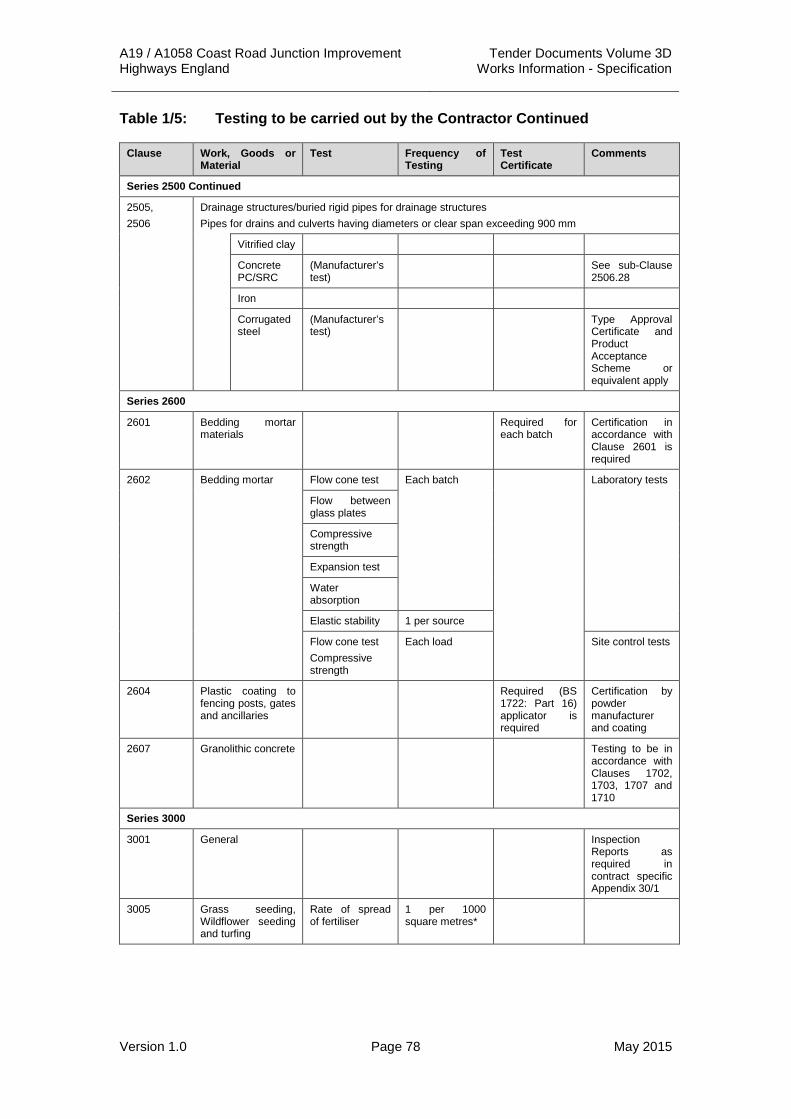
A19 / A1058 Coast Road Junction Improvement Tender Documents Volume 3D Highways England Works Information - Specification
Version 1.0 Page 78 May 2015
Table 1/5: Testing to be carried out by the Contractor Continued
Clause Work, Goods or Material
Test Frequency of Testing
Test Certificate
Comments
Series 2500 Continued
2505, 2506
Drainage structures/buried rigid pipes for drainage structures Pipes for drains and culverts having diameters or clear span exceeding 900 mm
Vitrified clay
Concrete PC/SRC
(Manufacturer’s test)
See sub-Clause 2506.28
Iron
Corrugated steel
(Manufacturer’s test)
Type Approval Certificate and Product Acceptance Scheme or equivalent apply
Series 2600
2601 Bedding mortar materials
Required for each batch
Certification in accordance with Clause 2601 is required
2602 Bedding mortar Flow cone test Each batch Laboratory tests
Flow between glass plates
Compressive strength
Expansion test
Water absorption
Elastic stability 1 per source
Flow cone test Compressive strength
Each load Site control tests
2604 Plastic coating to fencing posts, gates and ancillaries
Required (BS 1722: Part 16) applicator is required
Certification by powder manufacturer and coating
2607 Granolithic concrete Testing to be in accordance with Clauses 1702, 1703, 1707 and 1710
Series 3000
3001 General Inspection Reports as required in contract specific Appendix 30/1
3005 Grass seeding, Wildflower seeding and turfing
Rate of spread of fertiliser
1 per 1000 square metres*

A19 / A1058 Coast Road Junction Improvement Tender Documents Volume 3D Highways England Works Information - Specification
Version 1.0 Page 79 May 2015
Table 1/5: Testing to be carried out by the Contractor Continued
Clause Work, Goods or Material
Test Frequency of Testing
Test Certificate
Comments
Series 3000 Continued
3005 Cont’d Rate of spread of seeding
1 per 1000 square metres*
Chemical analysis of fertiliser
1 per source*
Grass seed germination and purity (Official Seed Testing Station tests)
1 per source and mix variety*
Required prior to sowing

A19 / A1058 Coast Road Junction Improvement Tender Documents Volume 3D Highways England Works Information - Specification
Version 1.0 Page 80 May 2015
APPENDIX 1/6: SUPPLY AND DELIVERY OF SAMPLES TO THE OVERSEEING ORGANISATION
Table 1/6: Supply and Delivery of Samples to the Overseeing Organisation
Clause Number or Series
Sample Description
Frequency of Sampling
Delivery Location
Comments
1200 Traffic Signal Duct
Once Site Compound
1900 Paint Samples Once Site Compound
Notes:
1 Samples comparable to those specified in this Appendix will be necessary for any equivalent work, goods or materials proposed by the Contractor (See sub-Clause 105.6 of the Specification for Highways Work).
2 Unless otherwise shown in this Appendix samples of work, goods or materials as scheduled under any one Clause are required for all such work, goods or materials in the Works.
3 Unless otherwise scheduled under Clause 2602 of the Specification for Highways Work samples of concrete complying with that Clause are not required.
4 (N) indicates UKAS or equivalent laboratory accreditation required for sampling.

A19 / A1058 Coast Road Junction Improvement Tender Documents Volume 3D Highways England Works Information - Specification
Version 1.0 Page 81 May 2015
APPENDIX 1/7: SITE EXTENT AND LIMITATIONS ON USE 1 Extent of the Site 1.1 Subject to the other provisions of the Contract, the extent of the Site shall be
as shown on the Red Line Boundary drawings (Ref: A19T-DWG-CIV-S00-0000-0001 to 0002 inclusive). The Contractor shall note that the Site extents defined on the Red Line Boundary drawings do not include for:
(i) Traffic Management layouts.
(ii) Temporary signing as required by Chapter 8 of the Traffic Signs Manual.
(iii) Permanent advance direction signing.
(iv) Lands owned or occupied by third parties where such lands are permitted to be accessed to execute and complete Retaining Wall Works.
1.2 In addition, and subject to the agreement of Highways England and / or the Local Highway Authority and written approval of the Project Manager, the extent of the Site shall include areas required for local traffic control measures by the Contractor, as and when necessary.
1.3
2 Limitations on Use of the Site 2.1 The Site shall be used solely for the execution and completion of the Works
including but not limited to remedying of Defects in the Works.
2.2 The normal working hours shall be Monday to Friday between 07:00 and 19:00 hours and between 07:00 and 13:00 hours on Saturdays, with no working on Sundays and public holidays. Exceptionally, the Project Manager’s written consent for work outside these hours may be given after necessary consultation. Seven days notice shall be required from the Contractor when seeking such consent.
2.3 Works other than works associated with providing, maintaining and removal of traffic management, the pumping out of excavations, security and emergency works shall not be undertaken at night and on weekends without the written consent of the Project Manager. Night is defined as 20:00 to 06:00 hours.
2.4 The Contractor’s attention is drawn to Appendix 1/9 of the Specification concerning limitations on noise and vibration.
2.5 The Contractors attention is drawn to Appendix 1/13 of the Specification and to the other Work Requirements concerning Site constraints and restrictions.
2.6 The Contractor shall be aware that third parties shall be operating within the extent of the Site and that those areas defined in Appendix 1/13 of the Specification and within this Appendix 1/7 shall not be for the sole use of the Contractor.
2.7 The Contractor shall not use areas of land with a temporary right of access, for any purpose other than the execution and completion of the Works including but not limited to the remedying of Defects.

A19 / A1058 Coast Road Junction Improvement Tender Documents Volume 3D Highways England Works Information - Specification
Version 1.0 Page 82 May 2015
2.8 The Contractor shall ensure that all areas of land, which have been temporarily occupied, shall be reinstated to the satisfaction of the affected landowner, occupier and the relevant Authorities, Utilities, Service Providers and Private Utility Services and other Companies.
2.9 Access for pedestrians, cyclists and other vehicular traffic shall be maintained to all properties along the existing route in accordance with the other provisions of the Contract.
2.10 Prior to entering parcels of land not acquired in their entirety, the Contractor shall erect suitable fencing (either permanent or temporary) taking into account adjacent land usage.
2.11 The safety zone specified in Chapter 8 of the Traffic Signs Manual shall be maintained between the edge of any traffic lane and the works, constructional plant or materials.
2.12 All areas outside the limits of the Site which are used or occupied by the Contractor shall be restored to their original condition on completion of the Works unless agreed with the landowner and local authority. Such restoration shall include any necessary reinstatement, re-soiling, seeding, or planting.
2.13 The Contractor's attention is drawn to the possible use of any working area by the Employer's Maintaining Agent Contractor including the provision, erection, maintenance, and removal of emergency traffic safety or maintenance measures that may be necessary whilst the works are being carried out.
2.14 No area of the Trunk Road shall be used for parking of vehicles used by or on behalf of the Contractor. The Contractor shall not obstruct any lane, road junction vehicular or pedestrian access which has not been closed to traffic.
2.15 The Contractor shall allow for any working areas within the boundaries of the highway to be used by vehicles requiring to stop in an emergency. The Contractor shall inform the Overseeing Organisation and the Police of the name(s) and telephone number(s) of a responsible person(s) who can be contacted at any time in an emergency.
2.16 The Contractor, his agents, servants or workmen shall not erect nor allow his sub-contractors, their agents, servants, or workmen to erect within the Site any advertisement. Should any advertisement be erected without such approval, the Overseeing Organisation shall have power to order in writing the Contractor to remove it forthwith. If the Contractor shall fail to comply with such order within 24 hours of its delivery to him, the Employer shall be entitled to employ and pay other persons to carry out the same and all expenses consequent thereon or incidental thereto shall be borne by the Contractor and shall be recoverable from him by the Employer or may be deducted by the Employer from any monies due or which become due to the Contractor.
2.17 The Contractor, or any agent or servant in his employ shall not give any information concerning the Works for publication in the press or broadcast on radio, television, cinema screen, or elsewhere without the written approval of the Overseeing Organisation.
2.18 The Contractor shall prevent trespass by his own or his sub-contractor’s employees onto any property adjoining the Site.

A19 / A1058 Coast Road Junction Improvement Tender Documents Volume 3D Highways England Works Information - Specification
Version 1.0 Page 83 May 2015
2.19 The Contractor shall ensure that no steps, ladders or other plant are left accessible so as to permit unauthorized access to the Works.
2.20 The Contractor shall maintain the Site in a clean and tidy state by removing rubbish and other debris arising from the works to a tip off Site. All materials and plant for the Works shall be stored neatly. On completion of the works the Contractor shall remove all surplus materials and leave the Site in a clean and tidy condition.
2.21 The Contractor shall note that traffic restrictions and traffic control required to carry out any necessary remedial works shall be to the standard required for the main works and all traffic control costs required for such remedial works shall be borne by the Contractor;
2.22 The programming of any remedial works required after the actual Completion Date for a Task Order shall be agreed with the Overseeing Organisation before commencement of those works.
2.23 Each goods vehicle used by the Contractor or his Subcontractors in connection with the contract shall display the vehicle license disc relevant to the goods operator’s license under which the vehicle is operated or, in the absence of an operator’s license disc, shall carry documentation giving the operator’s license number, name, and address.
2.24 Materials or plant shall not be stored at the following locations:
(i) within highway verges unless agreed with the Overseeing Organisation
(ii) in any location so as to impede the visibility of the traveling public
2.25 The Contractor shall note that traffic restrictions and traffic control required to carry out any necessary remedial works shall be to the standard required for the main works and all traffic control costs required for such remedial works shall be borne by the Contractor. The programming of any remedial works required after the actual Completion Date for a Task Order shall be agreed with the Overseeing Organisation before commencement of those works.
2.26 No area of carriageway shall be re-opened to traffic until a safe surface free from debris is available and all road markings have been reinstated.
2.27 Further restriction on traffic management are as detailed in Appendix 1/17.
2.28 Except with the prior written approval of the Overseeing Organisation, all vehicles transporting minerals or soil to or from the construction site shall be securely sheeted.
2.29 Liquid storage - All oil or chemical storage containers/drums including any such waste materials shall be stored in a compound with an impervious base with the floor constructed in such a manner that the contents of the largest container/drum are retained in the vent of a spillage. All waste materials such as oils, solvents, slurries or chemicals shall be disposed of at a site licensed to receive such materials.
2.30 Liquid storage - Any oil or liquid chemical storage tanks shall be located within a bund having a capacity of not less than 110% of the largest tank or the combined tank volume if a number of tanks are interconnected. The floor and walls of the bund shall be impervious to water and the stored liquid and all inlet, outlet and vent pipes and gauges shall be agreed in writing by

A19 / A1058 Coast Road Junction Improvement Tender Documents Volume 3D Highways England Works Information - Specification
Version 1.0 Page 84 May 2015
the County Planning Authority for the disposal of any contaminated water within the bund.
2.31 Landscaping - Prior to the commencement of any landscaping works on site, a detailed landscape scheme that indicates the proposed planting on site and the relationship of existing planting to adjoining planting on the highway and on adjacent land, shall be submitted to and approved in writing by the Overseeing Organisation. The submission shall include a mitigation strategy that addresses the mitigation of the scheme including its integration to the wider landscape. The scheme shall also include details of new native tree species to be planted as part of the replacement planting scheme. Once approved, the replanting scheme shall be carried out in accordance with the approved details and no later than the first available planting season following completion of the works.
2.32 Establishment and management of landscaping - Prior to the commencement of any landscaping works on site, details of a scheme to ensure a 5 year aftercare period and management for the proposed planting shall be submitted to and approved in writing by the Overseeing Organisation. The submission shall include details of the operational commitment to implement the details and programme over the aftercare period. Once approved, the development shall be carried out in accordance with the approved details.
3 Adjacent Works / Other Contractors 3.1 The Works to the Silverlink Roundabout shall be required to tie-in to the
Silverlink Retail Park Improvement scheme which is currently on-going.
3.2 The Contractor shall consult and comply with the requirements of the Silverlink Retail Park scheme contractor in the execution and completion of the Silverlink Roundabout Works as necessary to ensure that a smooth flowing alignment through the interface between the two schemes is provided.
3.3 The Contractor shall consult and comply with the requirements of any maintenance contractor employed by the Tyne Tunnel Company Ltd in the execution and completion of the Works.
4 Availability 4.1 The Contractor shall ensure that, in order to mitigate any potential
complaints due to the nuisance of the works, any properties within 250m of the site extents are letter-dropped a minimum of 5 days prior to commencement of the works or any changes to the normal working hours. The letter shall provide details of the date, working hours and nature of the works as well as a contact name and telephone number.
4.2 The content of any letter or advertisement is to be approved by the Overseeing Organisation prior to publication or issuing.
4.3 The contact number given in any letter-drops shall be manned during all working hours.
4.4 Copies of the letters issued by letter-drop shall be given to the Local Authority. Contacts detailed to be provided by the Overseeing Organisation.

A19 / A1058 Coast Road Junction Improvement Tender Documents Volume 3D Highways England Works Information - Specification
Version 1.0 Page 85 May 2015
5 Access 5.1 Access to and from the Site shall be from the highway network only. There
shall be no establishment of a site compound, site clearance, demolition, excavation or depositing of material in connection on the site until details of the routes to be used by HGV construction traffic have been submitted to and approved in writing by the Overseeing Organisation. Thereafter the approved routes shall be used by all vehicles connected with the construction site.
5.2 The Contractor shall look to minimise the use of the local highway authority
network by site vehicles and shall submit a logistics strategy document to the Overseeing Organisation for agreement 4 weeks prior to commencement of the works.
5.3 Direct access from the site compound will be permitted to enter the site. 5.4 There shall be no access or egress by any vehicles between the public
highway and the site until details of precautions to be taken to prevent the deposit of mud, grit and dirt on public highways by vehicles travelling to and from the site have been submitted to and approved by the Overseeing Organisation. These precautions, including wheel washing facilities, shall be made available before any excavation or depositing of material in connection with the construction commences on the site and be kept available and in full working order until a paved surface has been provided for use by site vehicles.
6 Winter Maintenance 6.1 The Contractor shall sluice (including the provision of clean water) any
working areas affected by grit and salt, so as to avoid de-bonding between layers of flexible construction.
6.2 The Area 14 MAC and North Tyneside Council’s will be responsible for gritting
and snow ploughing of the lanes open to traffic for the trunk road and local highway authority road networks respectively. The Contractor shall reset all disturbed cones, cylinders, lamps and signs and clear all snow and ice moved onto the working areas by the other Maintenance Contractors operations.

A19 / A1058 Coast Road Junction Improvement Tender Documents Volume 3D Highways England Works Information - Specification
Version 1.0 Page 86 May 2015
APPENDIX 1/8: OPERATIVES FOR THE OVERSEEING ORGANISATION
Table 1/8.1: Operatives for the Overseeing Organisation
Operatives Required Duties & Skills Number Period Required
Chainman/Driver Assist with surveying
Driving duties
1 From the Starting Date until Substantial Completion of the Works at an average of one day per week.

A19 / A1058 Coast Road Junction Improvement Tender Documents Volume 3D Highways England Works Information - Specification
Version 1.0 Page 87 May 2015
APPENDIX 1/9: CONTROL OF NOISE AND VIBRATION 1 General 1.1 The Local Authority having responsibility for the area is:
North Tyneside Council, Environmental Health,
Public Protection Services, Quadrant (East), Silverlink North,
Cobalt Business Park, North Tyneside, NE27 0BY
Tel: 0191 6436100
Email: [email protected]
2 Restrictions on Working Hours 2.1 Normal working hours on Site shall be as given in Appendix 1/7 of the
Specification.
3 Noise 3.1 The Contractor shall consult with the Local Authority with regards to his
proposed methods of Works, the plant and equipment to be utilised, the phasing of the operations and the steps he proposes in order to minimise noise. The Contractor shall obtain the written agreement of the Local Authority prior to the commencement of Works on the Site to such methods and steps, and shall obtain consents or other approvals where required by the Local Authority.
3.2 Prior to the commencement of any Works in connection with the project, the Contractor shall submit a formal Section 61 application under Part III of the Control of Pollution Act 1974 to the local Environmental Health Department. No Works shall commence on Site until the local Environmental Health Department shall have approved the Section 61 application, subject to such conditions as they consider reasonable.
3.3 Once approved, the Section 61 Consent shall be complied with in full; any amendments to the methods of operation required as the project progresses shall be discussed with the local Environmental Health Dept, and their agreement in writing shall be gained prior to any variations taking place.
3.4 It is for the Contractor to agree the measurement locations in detail with the Local Authority, together with the measurement frequency and duration of measurement exercises. The Contractor shall take cognisance of the following locations that were used for pre-construction noise monitoring:
(i) Silverdale School.
(ii) Dwellings in Tiverton Close.
(iii) Dwellings in Melrose Gardens.
(iv) Dwellings in Henley Gardens.
(v) McDonalds.
(vi) Travelodge Hotel (currently vacant).

A19 / A1058 Coast Road Junction Improvement Tender Documents Volume 3D Highways England Works Information - Specification
Version 1.0 Page 88 May 2015
(vii) Dwellings in Blakhill Avenue.
(viii) Dwellings in Bewick Park.
3.5 In order to ensure that the Works progress within the noise limits noted above, the Contractor shall arrange to undertake noise measurement during the Works. All measurements shall be undertaken by a Noise Specialist who is a full member of the Institute of Acoustics, with relevant post qualification experience in noise assessment. This Noise Specialist shall also be involved in the investigation of complaints, should any occur.
4 Vibration 4.1 The use of explosives is not permitted.
4.2 The Contractor shall select and utilise methods of working and items of plant so that the maximum measured ground vibrations do not exceed a peak particle velocity of 1mm per second at any occupied property and 3mm per second at any other property or structural element.
4.3 In exceptional circumstances the Contractor may exceed the specified limit of ground vibration, providing the Contractor demonstrates that he intends to take all reasonable measures to mitigate the nuisance and obtains the prior written approval of the Local Authority and the Project Manager.
4.4 The Contractor shall provide instrumentation suitable for monitoring vibration if any of the following occur:
(i) There is reasonable concern that the limits might be exceeded.
(ii) There are complaints from the public.
(iii) When required by the Supervisor.
4.5 Such monitoring shall include locations outside the limits of the Site, and shall be undertaken by the Noise Specialist noted above to be engaged on the project.

A19 / A1058 Coast Road Junction Improvement Tender Documents Volume 3D Highways England Works Information - Specification
Version 1.0 Page 89 May 2015
APPENDIX 1/10: PERMANENT WORKS TO BE DESIGNED BY THE CONTRACTOR
The Contractor shall design the following elements as listed in Table 1/10.1 below.
Table 1/10.1: Permanent Works to be designed by the Contractor
Element Location Design Specification
Safety Barrier As depicted on Drawing A19T-DWG-CIV-S00-0400-0001 to 0007 inclusive
The Contractor shall design the pedestrian guardrail in accordance with the requirements of Numbered Appendix 4/1.
Combined Drainage and Kerb Systems
As depicted on Drawings A19T-DWG-CIV-S00-0500-0001 to 0006 inclusive
The Contractor shall design the combined drainage and kerb systems in accordance with the requirements of Numbered Appendix 5/5.
Linear Drainage Systems
As depicted on Drawings A19T-DWG-CIV-S00-0500-0001 to 0006 inclusive
The Contractor shall design the linear drainage systems in accordance with the requirements of Numbered Appendix 5/6.
Instrumentation and Monitoring
As depicted on Drawing A19T-DWG-CIV-S00-0600-0001
The Contractor shall design the Instrumentation and Monitoring system in accordance with the requirements of Numbered Appendix 6/12.
Thin Surface Course System
As depicted on Drawing A19T-DWG-CIV-S00-0700-0001 to 0007 inclusive
The Contractor shall design the Thin Surface Course System in accordance with the requirements of Numbered Appendix 7/1.
Steps As depicted on Drawing A19T-DWG-CIV-S00-1100-0001 to 0007 inclusive
The Contractor shall design the steps in accordance with the requirements of Numbered Appendix 11/1.
Passive Traffic Signs
As depicted on Drawing A19T-DWG-CIV-S00-1200-0001 to 0007 inclusive.
The Contractor shall design the passive traffic signs in accordance with the requirements of Numbered Appendix 12/1.

A19 / A1058 Coast Road Junction Improvement Tender Documents Volume 3D Highways England Works Information - Specification
Version 1.0 Page 90 May 2015
Table 1/10.1: Permanent Works to be designed by the Contractor
Element Location Design Specification
Passive Road Lighting Column Foundations
As depicted on Drawing A19T-DWG-CIV-S00-1300-0001 to 0007 inclusive
The Contractor shall design the road lighting foundations in accordance with the requirements of Numbered Appendix 13/1.
Feeder Pillar Foundations
As depicted on Drawing A19T-DWG-CIV-S00-1300-0001 to 0007 inclusive
The Contractor shall design the feeder pillar foundations in accordance with the feeder pillar requirements.
Middle Engine Lane Railway Bridge
Middle Engine Lane Railway Bridge
The Contractor shall design the corrugated steel buried structure in accordance with the requirements of Appendix 25/1.
Bridge Deck Waterproofing System
As depicted on Drawing DWG-2000-001
The Contractor shall design the bridge deck waterproofing system in accordance with the requirements of Numbered Appendix 20/1.
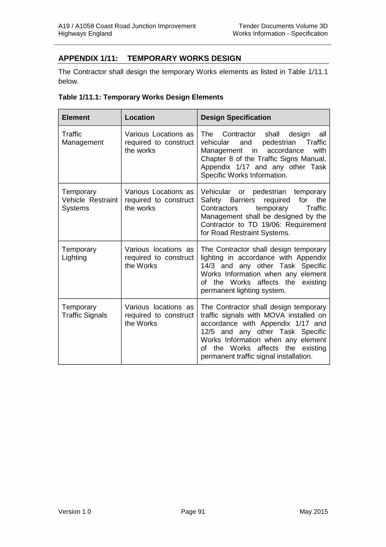
A19 / A1058 Coast Road Junction Improvement Tender Documents Volume 3D Highways England Works Information - Specification
Version 1.0 Page 91 May 2015
APPENDIX 1/11: TEMPORARY WORKS DESIGN The Contractor shall design the temporary Works elements as listed in Table 1/11.1 below.
Table 1/11.1: Temporary Works Design Elements
Element Location Design Specification
Traffic Management
Various Locations as required to construct the works
The Contractor shall design all vehicular and pedestrian Traffic Management in accordance with Chapter 8 of the Traffic Signs Manual, Appendix 1/17 and any other Task Specific Works Information.
Temporary Vehicle Restraint Systems
Various Locations as required to construct the works
Vehicular or pedestrian temporary Safety Barriers required for the Contractors temporary Traffic Management shall be designed by the Contractor to TD 19/06: Requirement for Road Restraint Systems.
Temporary Lighting
Various locations as required to construct the Works
The Contractor shall design temporary lighting in accordance with Appendix 14/3 and any other Task Specific Works Information when any element of the Works affects the existing permanent lighting system.
Temporary Traffic Signals
Various locations as required to construct the Works
The Contractor shall design temporary traffic signals with MOVA installed on accordance with Appendix 1/17 and 12/5 and any other Task Specific Works Information when any element of the Works affects the existing permanent traffic signal installation.

A19 / A1058 Coast Road Junction Improvement Tender Documents Volume 3D Highways England Works Information - Specification
Version 1.0 Page 92 May 2015
APPENDIX 1/12: SETTING OUT AND EXISTING GROUND LEVELS 1. The information given below will be available for inspection during the tender
period at:
Highways England
Lateral, 8 City Walk
Leeds, LS11 9AT
and will be supplied to the Contractor at the commencement of the Works.
2. The setting out of the Works and existing ground levels are shown on the drawings listed in Appendix 0/4 of this Specification.
3. The Contractor shall be responsible for the setting out of all parts of the Works including all information necessary to allow this to be set out properly.
4. Clearly marked chainage markers at 50 metre maximum intervals shall be executed by the Contractor at suitable locations for the duration of the execution of the Works.
5. Permanent ground markers and Secondary markers established by the Contractor to set out parts of the works shall be carefully preserved and protected against damage. Where the destruction or disturbance of a permanent marker becomes necessary the Contractor shall notify the Project Manager of his intention to render the marker unserviceable. Such a marker shall be replaced by a new marker at an agreed adjacent location. The Contractor shall submit to the Project Manager original field sheets and calculations to establish the co-ordinates and level of the replacement marker before the original marker is made unserviceable.
6. Where the Contractor establishes subsidiary permanent control markers, such markers shall be of a substantial type and construction, to the approval of the Project Manager.
7. Setting out pegs shall be colour coded according to their purpose using a colour code to be approved by the Overseeing Organisation. Any marking paints used by the Contractor shall be lead free and not use chloro-fluorocarbons. The Contractor shall exercise care in the use of site marking paint to avoid the permanent disfigurement of walls, fences, paving etc..
8. The Contractor shall set out the Works by reference to Ordnance Survey Datum (Newlyn), to which all levels in the Contract refer.
9. Horizontal alignment shall be determined in accordance with Ordnance Survey National Grid Co-ordinates, to which all reference to Northings and Eastings in the Contract refer.
10. Fourteen days in advance of the commencement of the Works affecting existing properties, the Contractor shall set out the Works for inspection if required by the Project Manager.
11. Measures to protect Statutory Undertakers equipment in accordance with their requirements will be required where they conflict with the Works.

A19 / A1058 Coast Road Junction Improvement Tender Documents Volume 3D Highways England Works Information - Specification
Version 1.0 Page 93 May 2015
APPENDIX 1/13: PROGRAMME OF WORKS 1 Form of Programme 1.1 In addition to the requirements of cl 31 and 32 of the Conditions of contract
and WI 505 of volume 3A, the Contractor shall provide the programme in the following form to comply with the constraints below.
1.2 The Contractor shall provide the programme in the form of a Gantt chart produced as a result of a “critical path analysis” and shall comply with the constraints stated or implied in the Contract. It shall show the level of detail appropriate to each stage of the Works and all activities and restraints, each of which shall be given a short title. All events shall be numbered and annotated with the earliest and latest event dates. The programme shall be supported by bar charts for particular activities or time scales at the request of the Project Manager.
1.3 At the time of presentation of the programme the Contractor shall also provide a mass-haul diagram showing his intended earthworks movement and locations and capacities of anticipated plant and other resource input.
1.4 All revision / updates to the above stated programme shall be supplied in hardcopy and digital formats to the Project Manager.
1.5 Where there is a local concentration of individual distinct operations which cannot be satisfactorily represented in enough detail on the Gantt Chart for the full length of the Works, for example at a junction or at a Structure, then an individual bar chart detailing such activities shall be provided to the Project Manager.
1.6 Additionally and notwithstanding any other provision of the Contract, the Project Manager shall have the right to require the Contractor to provide a bar chart for any part of the Works and the Contractor shall comply with such requirement at the cost of the Contractor.
1.7 Bar charts shall list the location and description of activities to which they refer and show for each listed activity a horizontal bar indicating the start, duration and stop date of that operation plotted to a horizontal scale of time.
2. Schedule of Constraints 2.1 The constraints stated below shall not be considered exhaustive and all
other constraints suggested or implied within the Contract or required by the Contractor for whatsoever reason including but not limited to following his inspection of the Site shall be taken into account by him in producing his programme.
2.2 The following Works are planned to be underway during the currency of the Contract and the Contractor shall take cognisance of these in his programme and shall consult with these other contractors and incorporate and co-ordinate their Works requirements within his programme.

A19 / A1058 Coast Road Junction Improvement Tender Documents Volume 3D Highways England Works Information - Specification
Version 1.0 Page 94 May 2015
Table 1/13.1: List of Planned Schemes
Name of Third Party Nature of Work
Highways England A19 Testos Junction Improvement Scheme
North Tyneside Council A1058 Norham Road Junction Scheme
North Tyneside Council A193 Wallsend Junction Improvement Scheme
Crown Estate Silverlink Retail Park Improvement Scheme
Area 14 MAC Maintenance of existing public roads.
North Tyneside Council Maintenance of existing public roads.
Northumbrian Water Maintenance of existing public water supplies.
Northern Powergrid Maintenance of existing public electricity supplies
Transco Maintenance of existing public gas supplies
British Telecom Maintenance of existing public telephone supplies
2.3 Acoustic fences and the like shall be executed at the earliest practicable date by the Contractor.
2.4 No private accesses shall be stopped up or curtailed in any way until an alternative accesses has been completed by the Contractor.
2.5 The Contractor shall allow sufficient time within his programme of Works to allow for the written consent by the Project Manager of sub-contractors and all other approvals, acknowledgements of receipt and the like as shall be required in accordance with the provisions of the Contract.
2.6 The Contractor shall note the requirements of Appendix 1/16 of the Specification in programming the alteration of services and supplies affected by the Works.
2.7 Where existing roads shall be crossed by the Contractor’s plant, the Contractor shall provide adequate traffic control and maintain the crossing as specified in Clause 117 of the Specification.
2.8 The Contractor shall note the requirements of Appendix 1/17 of the Specification in programming the Traffic Safety and Management Requirements.
2.9 The Contractor shall note the requirement to complete the communications installation 8 weeks before the date for completion of the works.
2.10 Night-time closures where permitted shall be restricted to between the hours of 22:00hrs to 06:00hrs.
2.11 Limitations on the use of the Site are given in Appendix 1/7.

A19 / A1058 Coast Road Junction Improvement Tender Documents Volume 3D Highways England Works Information - Specification
Version 1.0 Page 95 May 2015
2.12 The requirements of Appendix 1/9 shall be observed with respect to noise and vibration.
2.13 The requirements of Appendix 2/1 shall be observed with respect to site clearance of vegetation.
2.14 Areas of new carriageway are to be swept and road markings installed prior to re-opening.
2.15 At no time will the works be permitted to prevent pedestrian access to any property. Restrictions to vehicular access must be agreed in advance with the property owner and Overseeing Organisation.
2.16 There are no restrictions arising from the use of substances hazardous to health.
2.17 There is no requirement for the provision of environmental protection prior to the main construction operations (environmental barriers, etc.).
2.18 There is no requirement for trials and demonstrations in advance of main construction.
2.19 The schedule of testing of materials shall be as defined within Numbered Appendix 1/5 unless defined within a specific Numbered Appendix.
2.20 The Contractor shall give the Overseeing Organisation not less than 24 hours’ notice in writing of his intentions to commence any item of work to enable the Overseeing Organisation to make his arrangements for carrying out his supervision and inspections.
2.21 4 working hours’ notice is required for each inspection request unless otherwise specified.
2.22 It is the Contractor’s responsibility to apply for all traffic orders for closures of the A19 A1058 Coast Road, and Middle Engine Lane Bridleway.
3 Construction Programme
3.1 The level of detail to be provided within the Construction Programme shall be not less than that required by the Conditions of Contract

A19 / A1058 Coast Road Junction Improvement Tender Documents Volume 3D Highways England Works Information - Specification
Version 1.0 Page 96 May 2015
APPENDIX 1/14: PAYMENT APPLICATIONS 1.1 The payment applications shall be submitted in accordance with the
Conditions of Contract and WI 810 of volume 3A.

A19 / A1058 Coast Road Junction Improvement Tender Documents Volume 3D Highways England Works Information - Specification
Version 1.0 Page 97 May 2015
APPENDIX 1/16: PRIVATELY AND PUBLICLY OWNED SERVICES AND SUPPLIES
1.1 This Appendix contains details of services and supplies affected by the Works, details of preliminary arrangements that have been made with Statutory Undertakers, utility companies and others for the alteration of services and supplies affected by the Works, and details of any orders already placed.
1.2 The Contractor shall make arrangements with the Statutory Undertakers, utility companies and others concerned, for the co-ordination of his work with all work which needs to be done by them or their contractors concurrently with the Works. Compliance with the periods of notice given in this Appendix does not relieve the Contractor of his obligations.
1.3 Private services to individual properties have not generally been listed or shown on the Drawings. The Contractor shall make arrangements with the Statutory Undertakers and others concerned for the phasing of all necessary disconnections and diversion of private services affected by the Works.
1.4 The names, addresses and contact details of the Statutory Undertakers, utility companies and authorities serving in the locality are listed below.
Table 1/16.1: List of Statutory Undertakers, utility companies and Authorities
Names Address Contact Details
BT Openreach PP 4AB Newcastle Central TE Carliol Square Newcastle Tyne and Wear NE 1BB
Paul Mills Tel: 0191 269 6548 Email: [email protected]
Northumbrian Water Ltd.
Leat House Pattinson Road District 15 Washington Tyne Upon Wear NE38 8LB
Henry Hirsch Tel. 0845 604 7468 Email: [email protected]
Northern Powergrid (North East) Ltd.
New York Road Shiremoor Newcastle upon Tyne NE27 0LP
Alison Johnson Tel. 0191 229 4174 Email: [email protected]

A19 / A1058 Coast Road Junction Improvement Tender Documents Volume 3D Highways England Works Information - Specification
Version 1.0 Page 98 May 2015
Table 1/16.1: List of Statutory Undertakers, utility companies and Authorities Continued
Names Address Contact Details
Northern Gas Networks
1100 Century Way Thorpe Park Business Park Colton Leeds LS15 8TU
Intermediate Pressure Shaun Bosomworth Tel: 07816 066794 Email: [email protected]
Northern Gas Networks
1100 Century Way Thorpe Park Business Park Colton Leeds LS15 8TU
Medium Pressure Richard Chadwick Tel: 07824 143 351 Email: [email protected]
Virgin Media Diversionary Works Team Access Network Planning 1 Dove Wynd Strathclyde Business Park Bellshill ML4 3AL
John Haughey Tel: 0800 408 0088
A-one+ Area 14 MAC
Unit A Derwenthaugh Industrial Estate Derwenthaugh Road Swalwell Tyne & Wear NE16 3BQ.
TBC Tel: 01325 389 991 Email: [email protected]
Atkins Telecoms For: Cable/ Wireless & Energis Communications
The Hub, 500 Park Avenue, Almondsbury, Bristol, BS32 4RZ
Environment Agency
North East Team Tyneside House Skinnerburn Road Newcastle-upon-Tyne NE4 7AR

A19 / A1058 Coast Road Junction Improvement Tender Documents Volume 3D Highways England Works Information - Specification
Version 1.0 Page 99 May 2015
Table 1/16.1: List of Statutory Undertakers, utility companies and Authorities Continued
Names Address Contact Details
INSTALCOM Specialists in Civils & Cabling Installation
Plant Protection Administrator Instalcom House Manor Way Borehamwood WD6 1QH
North East Technology MAC Amey LG Ltd.
The Sherard Building Oxford Science Park Edmund Halley Road Oxford OX4 4DQ
SSE – Scottish and Southern Contracting Group
Unit 7 Franklin Industrial Estate Blaydon Haugh Blaydon Tyne & Wear NE21 5TL
North Tyneside Council
Community Services Directorate Quadrant The Silverlink North Cobalt Business Park North Tyneside NE27 0BY
1.5 The following services and supplies are affected by the Works:
Table 1/16.2: List of Services and Supplies affected by the Works
Location Description Group* Drawing No. Details
Silverlink Roundabout North Bridge
Divert existing BT cables over new bridge.
C A19T-DWG-CIV-S00-2700-0001 Rev A
TBC
Silverlink Roundabout North Bridge
Divert existing LV and HV cables from roundabout verge to go over new bridge.
C A19T-DWG-CIV-S00-2700-0001 Rev A
TBC
Silverlink Roundabout North Bridge
Divert existing water main over new bridge.
C A19T-DWG-CIV-S00-2700-0001 Rev A
TBC
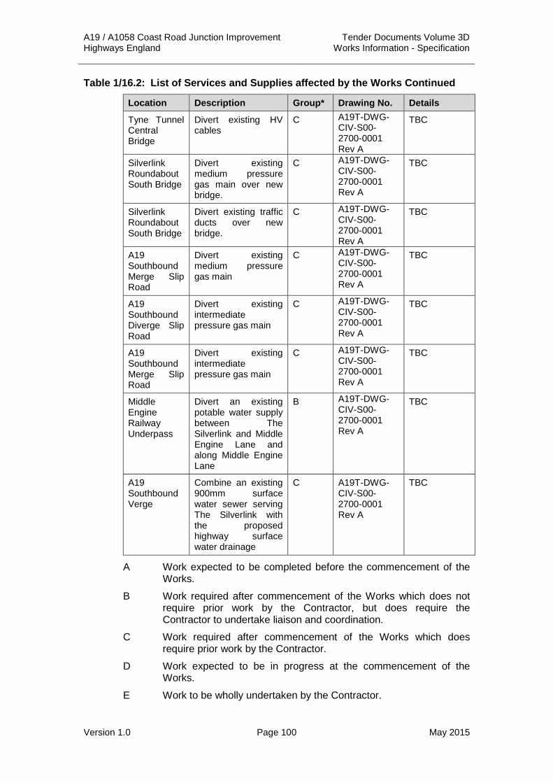
A19 / A1058 Coast Road Junction Improvement Tender Documents Volume 3D Highways England Works Information - Specification
Version 1.0 Page 100 May 2015
Table 1/16.2: List of Services and Supplies affected by the Works Continued
Location Description Group* Drawing No. Details
Tyne Tunnel Central Bridge
Divert existing HV cables
C A19T-DWG-CIV-S00-2700-0001 Rev A
TBC
Silverlink Roundabout South Bridge
Divert existing medium pressure gas main over new bridge.
C A19T-DWG-CIV-S00-2700-0001 Rev A
TBC
Silverlink Roundabout South Bridge
Divert existing traffic ducts over new bridge.
C A19T-DWG-CIV-S00-2700-0001 Rev A
TBC
A19 Southbound Merge Slip Road
Divert existing medium pressure gas main
C A19T-DWG-CIV-S00-2700-0001 Rev A
TBC
A19 Southbound Diverge Slip Road
Divert existing intermediate pressure gas main
C A19T-DWG-CIV-S00-2700-0001 Rev A
TBC
A19 Southbound Merge Slip Road
Divert existing intermediate pressure gas main
C A19T-DWG-CIV-S00-2700-0001 Rev A
TBC
Middle Engine Railway Underpass
Divert an existing potable water supply between The Silverlink and Middle Engine Lane and along Middle Engine Lane
B A19T-DWG-CIV-S00-2700-0001 Rev A
TBC
A19 Southbound Verge
Combine an existing 900mm surface water sewer serving The Silverlink with the proposed highway surface water drainage
C A19T-DWG-CIV-S00-2700-0001 Rev A
TBC
A Work expected to be completed before the commencement of the Works.
B Work required after commencement of the Works which does not require prior work by the Contractor, but does require the Contractor to undertake liaison and coordination.
C Work required after commencement of the Works which does require prior work by the Contractor.
D Work expected to be in progress at the commencement of the Works.
E Work to be wholly undertaken by the Contractor.

A19 / A1058 Coast Road Junction Improvement Tender Documents Volume 3D Highways England Works Information - Specification
Version 1.0 Page 101 May 2015
1.6 The following preliminary arrangements have been made for the diversion of services and supplies that are affected by the Works.
Table 1/16.3: Estimated C4 Costs of Diversions
Location and Description Total Estimate Cost* (excluding VAT)
BT Openreach £372,366.69
Northumbrian Water Ltd – Potable Water £76,795.32
Northumbrian Water Ltd – Drainage £503,949.04
Northern Powergrid (North East) Ltd. £126,301.32
Northern Gas Networks £1,561,007.74
Virgin Media ** £24,097.23
Sub-Total £2,640,420.11
VAT £528,084.02
Total £3,168,504.13
*. Includes Statutory Undertakers Discount of 18%
** Not included in Totals
Note: Current estimates date back to June 2014, on award of contract, the Contractor shall liaise with the affected parties to gain an up to date cost for the Works required.
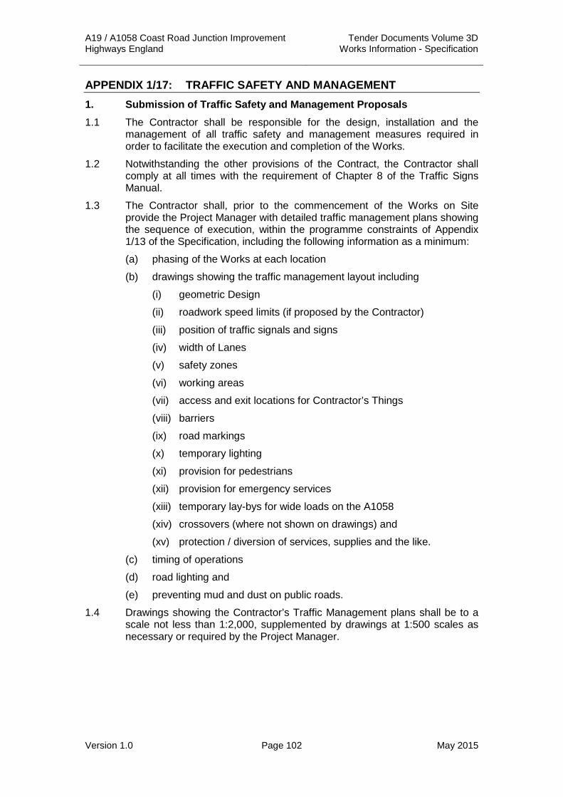
A19 / A1058 Coast Road Junction Improvement Tender Documents Volume 3D Highways England Works Information - Specification
Version 1.0 Page 102 May 2015
APPENDIX 1/17: TRAFFIC SAFETY AND MANAGEMENT 1. Submission of Traffic Safety and Management Proposals 1.1 The Contractor shall be responsible for the design, installation and the
management of all traffic safety and management measures required in order to facilitate the execution and completion of the Works.
1.2 Notwithstanding the other provisions of the Contract, the Contractor shall comply at all times with the requirement of Chapter 8 of the Traffic Signs Manual.
1.3 The Contractor shall, prior to the commencement of the Works on Site provide the Project Manager with detailed traffic management plans showing the sequence of execution, within the programme constraints of Appendix 1/13 of the Specification, including the following information as a minimum:
(a) phasing of the Works at each location
(b) drawings showing the traffic management layout including
(i) geometric Design
(ii) roadwork speed limits (if proposed by the Contractor)
(iii) position of traffic signals and signs
(iv) width of Lanes
(v) safety zones
(vi) working areas
(vii) access and exit locations for Contractor’s Things
(viii) barriers
(ix) road markings
(x) temporary lighting
(xi) provision for pedestrians
(xii) provision for emergency services
(xiii) temporary lay-bys for wide loads on the A1058
(xiv) crossovers (where not shown on drawings) and
(xv) protection / diversion of services, supplies and the like.
(c) timing of operations
(d) road lighting and
(e) preventing mud and dust on public roads.
1.4 Drawings showing the Contractor’s Traffic Management plans shall be to a scale not less than 1:2,000, supplemented by drawings at 1:500 scales as necessary or required by the Project Manager.

A19 / A1058 Coast Road Junction Improvement Tender Documents Volume 3D Highways England Works Information - Specification
Version 1.0 Page 103 May 2015
2. Traffic Safety and Management Requirements and Constraints 2.1 The Contractor shall ensure that a minimum of two running lanes of traffic in
both directions shall be maintained on the A19 and A1058 Coast Road between 06:00 hours and 20:00 hours on weekdays and weekends.
2.2 Alternatively, each or both carriageways of the A19 and A1058 Coast Road may be closed, or have the number of lanes reduced, outside the hours stated in paragraph 2.1 above. This will necessitate approval of a TTRO by Highways England’s Network Delivery and Development Directorate (NDD) or North Tyneside Council.
2.3 The erection and removal of any traffic management or temporary diversion shall not be carried out during the following hours: Monday to Friday – 06:00 to 20:00 hours and on any local or national public holiday.
2.4 The Contractor shall note the requirement to provide temporary traffic signals on The Silverlink Roundabout that incorporate MOVA in accordance with TD 35/06 All Purpose Trunk Roads MOVA System of Traffic Control at Signals of the DMRB at all times.
2.5 Unless otherwise authorised by the Project Manager, traffic management measures which could cause traffic flows to be impeded or restricted are to be removed for bank holiday periods as set out below:
Bank Holiday Mondays Traffic management to be removed before 06:00 on the Friday before the bank holiday Monday and not reinstated before 00:01 on the Tuesday after the bank holiday.
Easter Traffic Management to be removed before 06:00 on the Thursday before Good Friday and not reinstated before 00:01 on the Tuesday after Easter Monday.
Christmas Traffic Management to be removed before 06:00 on the morning of the third working day* before Christmas Day and not reinstated before 00:01 on the first working day* following the New Year’s Day bank holiday.
* Note: “working day” means a weekday, but not a Saturday or Sunday. A “working day” would include Christmas Eve where it falls on a weekday.
2.6 The Contractor’s Traffic Safety and Management method statement shall include proposals for an emergency route for emergency services vehicles if they are delayed when using the public trafficked area of the works.

A19 / A1058 Coast Road Junction Improvement Tender Documents Volume 3D Highways England Works Information - Specification
Version 1.0 Page 104 May 2015
2.7 Notice required by the Project Manager in order to arrange for:
(a) Amending or making traffic orders is twelve weeks
(b) Authorising temporary traffic signals is four weeks
(c) Moving signs to be compatible with the state of the Works is eight weeks
2.8 The Contractor shall take cognisance of the following local events that may impact on his traffic management proposals:
Table 1/17.1: List of Local Events
Event 2014 date Organiser
New Years Day Dip, Whitley Bay 1 January NSVL
Monkseaton Morrismen, The Ship Inn
1 January MMM
Warrior Beach Assault 29 March Total Racing International
Spanish City Funfair, Whitley Bay 12-21 April Turners Funfairs
Tynemouth Book Fair, Tynemouth Station
13 April Ylana First
Kids Town Centre Takeover 10 - 12 April NTC
North Tyneside 10k Road Race 21 April NTC
Tynemouth Fake Festival, Percy Park Rugby Football Club
3 May Fake Festivals
Tynemouth Food Festival, Tynemouth Priory
10-11 May Sally Craigen
South Shields Proper Food and Drink Festival
23 – 25 May Mark Deakin
Iron Age Festival, Cullercoats May Peter Mortimer
Love Your Local Market, Whitley Bay
17 May NTC
The Big Lunch – street parties in various locations
1 June General Public
Armed Forces Day ceremony 23 June NTC
Whitley Bay Proper Food and Drink Festival
June Mark Deakin
Tynemouth Book Fair, Tynemouth Station
15 June Ylana First
Shiremoor Treat 5 July VODA
Wallsend Festival 5-6 July NTC
Mouth of the Tyne Festival 10-13 July NTC
Tynemouth Beach Volleyball Tournament
12-13 July Sue Sowden

A19 / A1058 Coast Road Junction Improvement Tender Documents Volume 3D Highways England Works Information - Specification
Version 1.0 Page 105 May 2015
Table 1/17.1: List of Local Events Continued
Event 2014 date Organiser
Cullercoats Harbour Day 19 July RNLI
RNLI Day @ North Shields Fish Quay
20 July RNLI
Tynemouth Classic Volkswagen Rally
26 July Jill Snailham
Whitley Bay Sandcastle Competition
July 27 NTC / WBCT
Great Yorkshire Show – Great Yorkshire Showground
July 2014
Burgham Horse Trials – Morpeth July 2014
Sunderland International Airshow - Sunderland
July 2014 Sunderland CC
Gateshead Flower Show - Gateshead
July 2014 Gateshead MBC
Stockton International Riverside Festival ,Stockton – on - Tees
July 2014
Tynemouth Book Fair, Tynemouth Station
3 August Ylana First
Beach Party – King Edward’s Bay 16 August Paul Stewart
Whitley Bay Film Festival 16-31 August Primate Productions
Spanish City Triathlon, Whitley Bay
17 August Total Racing International
Great North Bike Ride 24 August Chris Lucas Trust
North Shields Proper Food Festival, Northumberland Square
August Mark Deakin
Heritage Open Days 11-14 Sept Local Councils
Whitley Bay Classic Car Show 21 September NTC
Tunnel 2k wheelchair race (Night) September David Burdis
Mini Great North Run 14 Sept 2014 The Great Run Company
Junior Great North Run 14 Sept 2014 The Great Run Company
Great North Run 15 Sept 2014 The Great Run Company
Tynemouth Book Fair, Tynemouth Station
19 October Ylana First
Scary Tales at Tynemouth Priory October NTC
Trafalgar Day 21 October NTC
Shimmer Digital Arts Festival November NTC
North Tyneside Fire Works Display
2 November NTC
Firework in the Fort, Segedunum Roman Fort
5 November NTC

A19 / A1058 Coast Road Junction Improvement Tender Documents Volume 3D Highways England Works Information - Specification
Version 1.0 Page 106 May 2015
Table 1/17.1: List of Local Events Continued
Event 2014 date Organiser
Remembrance Sunday 9 November NTC
NTC Christmas Light Switch-on, North Shields
21 November NTC
Christmas lights switch on, Royal Quays Shopping
November Royal Quays Outlet Centre
Railex NE Model Railway Show December Chris Stafford
St Nicholas Festival, Whitley Bay 5-6 December NTC
Whitley Bay Chamber of Trade Christmas Fayre
7 December Whitley Bay Chamber of Trade
North Shields Victorian Christmas Market
13-14 December NTC / Partnership
Boxing Day Pudding Run, The Links, Whitley Bay
26 December Whitley Bay Chamber of Trade
Sunderland AFC home games July to May Sunderland FC
Middlesbrough FC home games July to May Middlesbrough FC
Newcastle United FC home games
July to May Newcastle FC
Newcastle Falcons RUFC home games
September to May
Newcastle Falcons RUFC
Events at Metro Radio Arena All year round Metro Radio Arena
Horse Racing April to December
Newcastle Race Course
3. Traffic data 3.1 The traffic data required for traffic management design is shown in the
Traffic Forecasting Report (Ref: rp-mps-Traffic Forecasting Report-280910) prepared by Arup Consulting Engineers in 2012.
3.2 The bus routes using the roads within the Site boundary at the time of Tender are as follows:
Table 1/17.2: Bus Routes
Road Link Bus Service
A1058 306
309
The Silverlink 18
19
Middle Engine Lane 80
309
310
335

A19 / A1058 Coast Road Junction Improvement Tender Documents Volume 3D Highways England Works Information - Specification
Version 1.0 Page 107 May 2015
4. Maintenance Requirements 4.1 The Contractor shall be responsible for maintaining all traffic management
equipment, including cleaning of signs, cones, cylinders, barriers and the like and keeping them in good order.
4.2 The Contractor shall ensure that the traffic management equipment is continuously inspected and, where necessary, immediately properly reinstated. The Contractor shall provide on-Site, operatives and appropriate vehicles for the exclusive purpose of carrying out continual inspection (i.e. twenty four hours per day, seven days per week) of the traffic safety and control systems from commencement to completion of the Works.
4.3 The Contractor shall be responsible for the routine maintenance functions throughout the whole of the Works to be carried out on any area of the highway utilised by the general road user for the duration of the Works and within the confines of the Site as detailed in Appendix 1/7. For the trunk road networks, these responsibilities will include:
(i) Maintenance of both the existing highway and new build constructed as part of the scheme.
(ii) Maintenance is not just the pavement (e.g. pot holes) but all aspects of highway maintenance e.g. grass cutting of visibility splays, lighting outages, third party damage (and any third party green & red claims), drainage (e.g. no flooding on the carriageway), environmental (e.g. controlling ragwort, management of overhanging vegetation), incident management (e.g. liaising & assisting Police at an incident) in accordance with the NMM.
(iii) Extents of this responsibility must be agreed with Highways England NDD and North Tyneside Council in conjunction with the Area 14 MAC and be marked on a scaled plan.
(iv) Safety Inspections and Safety Patrols; as defined in the current edition of the Highway England’s Network Management Manual (NMM) or subsequent upgrades including the logging of all such patrols and any defects located. Nil returns of defects shall be made.
4.4 Safety Inspections and Safety Patrols shall be carried out by the Contractor on a daily basis.
4.5 Any defect located categorised as a Category 1 defect as defined in the NMM or any subsequent Highways England documentation shall be corrected by the Contractor. Category 2 defects being notified to the Project Manager within twenty four hours of the defect being encountered.
4.6 All Category 1 defects within the Traffic Management, however caused, shall be rectified by the Contractor. All defects shall be corrected within the time periods shown in the NMM unless the defect is considered dangerous and providing that the repair is carried out within the allotted time period.
4.7 Where any area of the Site is to be returned to use by the general road user the Contractor shall carry out a separate Safety Inspection of that area and shall ensure that the carriageway is swept and there are no defects or deficiencies in that area before returning the area to the general road user.
4.8 The Contractor shall patch, sweep and otherwise maintain the trafficked carriageway surfaces within the traffic management system to allow traffic to pass safely within the speed restrictions of the Site.

A19 / A1058 Coast Road Junction Improvement Tender Documents Volume 3D Highways England Works Information - Specification
Version 1.0 Page 108 May 2015
5. Breakdown Recovery 5.1 Breakdown Recovery shall be provided in accordance with the requirements
of Appendix 1/20 of this Specification.
6. Traffic Safety and Control Officer (TSCO) 6.1 A Traffic Safety and Control Officer (TSCO) will be required to carry out the
duties as specified in this Appendix. The TSCO and their nominated deputy shall be employees of the Contractor, or subcontractors engaged directly by the Contractor solely for the purpose of the duties of the TSCO. The TSCO and his nominated deputy shall not be engaged or employed by the traffic management subcontractor. Where the Contractor is undertaking the traffic management directly, or the Contractor and the traffic management subcontractor are part of the same holding company, the TSCO and their deputy shall be engaged from an independent source, by and be responsible to, the division of the holding company acting as the Contractor.
6.2 The responsibilities of the TSCO and of their nominated deputy shall include but not be limited to the following:
(i) One of either to be in twenty four hour contact with all recovery vehicles by a radio system and in addition to mobile telephone system.
(ii) Monitoring, with the assistance of sufficient mobile personnel and of sufficient other suitable and appropriate aids, the flow of traffic within the area and within the period defined for the operation of the vehicle recovery service.
(iii) Ensuring that, within five minutes of notification of the occurrence of an incident as defined below, resulting in stationary vehicle(s) on a highway open to the public, the incident is reported to the vehicle recovery service.
(iv) Recording and logging all incidents and all movements of recovery vehicles and, when called, all movements of the emergency services.
(v) For the purposes of this Appendix, an "incident" is defined as a shed load, vehicle breakdown, vehicle abandonment or traffic accident, whether or not involving personal injury.
(vi) Traffic management bookings, procedures and reports as detailed in this Appendix.
(vii) In addition to the booking report above, by 16:00 hours on the Monday of each week the TSCO shall submit a report to the Project Manager detailing the Traffic Management and Safety systems in operation during the previous week. The report shall include but not be limited to the following:
• Any Traffic Management and Safety systems in operation including dates and times of installation, removal or alteration.
• Records of traffic management inspections including the name of the inspector.
• Records of the incidents logged under item (iii) above.
• Records of damage to any part of the traffic safety and management systems including the date and time that the

A19 / A1058 Coast Road Junction Improvement Tender Documents Volume 3D Highways England Works Information - Specification
Version 1.0 Page 109 May 2015
incident occurred and the date and time when the damage was repaired.
• Recording and logging all incidents and all movements of recovery vehicles and, when called, all movements of the emergency services.
• For every traffic management installation recording and logging the times and dates the calls to the National Traffic Control Centre (NTCC) and Regional Control Centre (RCC) were made, the relevant Scheduled Road Works (SRW) number, RCC reference number and the name of the NTCC operator.
(viii) Other Surveillance of any signing remote from the Site, particularly signing outside the limits of the advance signs.
(ix) Control of entry and exit of the works site traffic onto the carriageway in general use.
(ix) Controlling the safe working of plant, machinery and men immediately adjacent to the carriageway open to traffic.
(x) Inspection and maintenance of all equipment described, arranging duties for watchmen so that the Site is patrolled and inspected at all times and equipment attended to as required and for dealing with traffic in emergencies including notifying the Police immediately of any accidents and emergencies.
(xi) To notify the Contractor of any deterioration of safety precautions including any part of the traffic management, traffic signs and carriageway road surface.
6.3 The TSCO is required to consult and comply with the requirements of the Highways England NTCC and RCC in the course of their duties.
7. Temporary Traffic Regulation Orders 7.1 The Contractor shall obtain all Temporary Traffic Regulations Orders
(TTRO) from Highways England or an appropriate highway authority necessary to programme and complete the Works. Prior to submission of the application the Contractor shall obtain approval of any proposed TTRO from the Project Manager.
8. Crossovers 8.1 The Contractor shall design and install any such crossovers required by the
Contractors Traffic Safety and Management Proposals in accordance with the following documents:
(i) TA 92 Crossover and Changeover Design of the DMRB.
(ii) Chapter D6.5 Crossovers of Chapter 8 Traffic Safety Measures and Signs for Road Works and Temporary Situations Part 1: Design.
9. Temporary Lay-bys 9.1 The Contractor shall design, construct and remove two temporary lay-bys for
wide loads to park in whilst awaiting clearance to drive through the Works on the A1058 in accordance with the following documents:
(i) TD 69 The Location and Layout of Lay-bys and Rest Areas of the DMRB.

A19 / A1058 Coast Road Junction Improvement Tender Documents Volume 3D Highways England Works Information - Specification
Version 1.0 Page 110 May 2015
10. Driver Information Signs 10.1 Before any member of the workforce crosses a live carriageway, “Workforce
in Road Slow” signs shall be erected. The crossing of a live carriageway shall only be permitted in the following circumstances:
• Establish temporary traffic management signs.
• Removal of temporary traffic management signs.
• Retrieval of debris when instructed.
10.2 Members of the workforce required to cross the carriageway shall be physically capable of crossing the carriageway, possibly carrying a sign or cones as necessary. The “Workforce in Road Slow” signs shall be removed as soon as Works involving people crossing the carriageway are complete.
10.3 In addition to those signs required by the Works the Contractor shall provide, erect, maintain, reposition, cover and uncover and remove the following driver information signs in accordance with the requirements of clause 117 of the Specification for Highway Works. The appropriate sign style and legend shall be taken from Interim Advice Note 64/05. Where signs are required to be in pairs one sign shall be erected on each side of the carriageway:
(i) Advance Signing to Diag. 7003.1 of the Traffic Signs Regulations and General Directions 2002 (TSRGD) showing the starting date and duration of the road Works shall be placed in the nearside verge of the A19 and the A1058 Coast Road at the location of the start of Works four weeks prior to the commencement of any Works or carriageway closures. The signs shall be removed on completion of the works.
(ii) Road Works Ahead signs to Diag. 7002A of the TSRGD indicating major road Works ahead shall be erected upstream of the following junctions at the commencement of any works. The signs shall be removed on the completion of the works. The bottom panel shall read “Delays possible”.
a. A19 / A191 Holystone Junction
b. A1058 Norham Road Junction
c. A19 / A193 Tynemouth Road Junction
d. A1058 / A186 Station Road Junction
(iii) When no Site activity is visible to the travelling public for a period exceeding twenty four hours lane closure information signs to Diag. 7004 of the TSRGD shall be erected not less than 50 m beyond the downstream end of each entry taper at locations to be agreed with the Project Manager.
(iv) End of Road Works, Highways England Information Line (formerly known as HAIL) signs to Diag. 7006.1 of the TSRGD shall be placed in the near side verge approximately 200 m downstream from the end of Works sign.
(v) Average speed check signs to Diag. 878.1 shall be placed between 50m and 100m upstream of the initial temporary mandatory speed limit signs at locations to be agreed with the Project Manager. Signs shall be provided in pairs. Speed camera repeater signs to Diag. 879 of the

A19 / A1058 Coast Road Junction Improvement Tender Documents Volume 3D Highways England Works Information - Specification
Version 1.0 Page 111 May 2015
TSRGD shall be provided 50 – 100 m in advance of each average speed camera pole.
(vi) Vehicle Recovery Signs, free breakdown recovery service signs to Diag. 7291 of the TSRGD shall be provided for the period specified in Appendix 1/20. Signs shall be located at intervals not exceeding 800 m on alternate sides of the carriageway commencing at a point immediately prior to the entry taper.
(vii) End of free recovery service signs to Diag. 7291 of the TSRGD shall be erected at a point immediately beyond the “Roadworks End” sign at locations agreed with the Project Manager.
(viii) Wide Load Signs to Diag. 7292 of the TSRGD with contact phone number shall be erected at the existing lay-bys on the A19 at either end of the scheme.
(ix) Wide Load Signs to Diag. 7292 of the TSRGD with contact phone number shall be erected at the temporary lay-bys that shall be provided by the Contractor on the A1058 at either end of the scheme.
(x) Lane Closed for Safety Signs to Diag. 7004 Style B of the TSRGD shall be provided whenever any such lane closures shall be required by the Contractors Traffic Safety and Management Proposals in accordance with the requirements of Clause 117 of the Specification for Highway Works.
11. Temporary Speed Limit Cameras 11.1 The Contractor shall design, execute and complete speed check
enforcement along the A19 and the A1058 Coast Road. Exceptions may be permitted in agreement with the Police, Highways England and North Tyneside Council.
12. Other Traffic Safety and Management Requirements 12.1 The Contractor shall comply with the requirements and recommendations of
the following publications:
(i) Highways England Network Management Manual. Part 4 – Traffic Management.
(ii) Chapter 8 of the Traffic Signs Manual & Notes for Guidance on ‘Safety at Road works.
(iii) Highways England Speed Limit Enforcement at Road works: Guidance and Best Practice which offers advice on procedures to follow when carrying out this activity. The Service Provider is strongly advised to take this guidance into account when planning major schemes where the speed limit is to be enforced.
(iv) Highways England Safety Camera Partnership Guidance provides guidance on working with partnerships operating speed cameras.
(v) Specification for Highway Works Clause 117 and sub-clauses.
12.2 Traffic shall not be diverted until after the approval of each stage by the Project Manager. No personnel or items of plant (other than required for the signing and coning operations) shall enter a newly closed carriageway traffic lane until such time as the traffic has been satisfactorily diverted and approval to commence work given by the Project Manager.

A19 / A1058 Coast Road Junction Improvement Tender Documents Volume 3D Highways England Works Information - Specification
Version 1.0 Page 112 May 2015
12.3 Full closures of the A19 and A1058 shall be kept to a minimum. Where the Contractor wishes to temporarily divert traffic using the A19T, the signed diversion shall be via the Highways England network wherever reasonably practicable.
12.4 The reversing and positioning of vehicles to a specific operation or item of plant shall only be undertaken under the direction of a designated marshal or banks man who escorts the vehicle whilst reversing. The Contractor shall erect signs at each Works access to inform drivers of this requirement that all such reversing of vehicles shall be undertaken under the direction of the designated marshal or banks man. The Contractor shall supply details of his proposed sign to the Project Manager for approval.
12.5 Where the circumstances of any particular case are not covered by the Traffic Signs Manual, these publications and the drawings, the Contractor shall submit proposals for dealing with such situations to the Project Manager for approval. Compliance with this Clause shall not relieve the Contractor of any of his other obligations and liabilities under the contract and under the relevant provisions of the Highways Acts.
12.6 The Contractor shall not commence any permanent work which affects the public highway until all traffic safety measures necessitated by the work are fully operational and have been approved by the Project Manager. In addition, before any work is carried out within the boundaries of the highway and before any vehicles or plant are parked on the Highway, other than those used for setting up traffic management systems, arrangements shall be made with the Project Manager's Maintenance Manager and with the Police, all of whom shall be kept informed of the programming of the Works in advance.
12.7 The Contractor should note that the highway will be open to traffic, though in restricted capacity, during the whole period that the Works are in progress. Without prejudice to the other provisions of this contract the Contractor must ensure that no actions by him or his employees or sub-contractors or his suppliers or his haulers or their employees are executed in such a manner as to constitute hazards or safety risks to traffic or themselves.
12.8 No area of carriageway shall be re-opened until a safe surface, free from debris and of sufficient skidding resistance, is available for traffic.
12.9 The Contractor’s Traffic Safety and Management Proposals shall ensure that construction joints in the surface course comply with Clause 903.21 of the Specification for Highways Works.
12.10 All vehicles used on Site shall be fitted with a roof mounted amber flashing beacon as a minimum. The use of a vehicles hazard warning lights shall not be acceptable on Site.
12.11 The Contractor’s attention is drawn to the requirement for Stage 2 Road Safety Audits for their Traffic Management and Safety Proposals.
12.12 Heavy Commercial Vehicles used on Site by the Contractor, his Sub-contractors or suppliers shall be fitted with an audible reversing warning device.
12.13 Works which shall be carried out adjacent to live traffic shall be adequately protected by continuous barriers separating them from the vehicular traffic.

A19 / A1058 Coast Road Junction Improvement Tender Documents Volume 3D Highways England Works Information - Specification
Version 1.0 Page 113 May 2015
12.14 Regular meetings shall be arranged by the Contractor between the Project Manager, Contractor, the Police and any relevant highway authority and take place throughout the duration of the Works. These meetings shall take account of any special events that may require special traffic management measures.
13. Temporary Signing, Road Markings and Studs 13.1 The Contractor shall provide all the signs, cones, temporary road studs and
markings required for the Works in accordance with Chapter 8 of the Traffic Signs Manual.
13.2 Existing permanent traffic sign faces shall be masked by an opaque material, approved by the Project Manager, when not required or when giving conflicting information to drivers or as directed by the Project Manager.
13.3 All signs shall be in Class RA2 reflective material and shall be regularly cleaned.
13.4 Temporary signs that shall be mounted over footways, cycleways and bridleways shall be installed in accordance with Chapter 8 Headroom of TA 90 The Geometric Design of Pedestrian, Cycle and Equestrian Routes of the DMRB. The Contractor shall submit his proposals for the affixing of any such signs to the Project Manager seven days prior to the commencement of these Works.
13.5 All conflicting road markings shall be removed or obscured whilst temporary working is in operation.
13.6 The Contractor shall design and erect appropriate diversion and information signs in accordance with Traffic Signs Manual Chapter 8 and Traffic Signs Regulations and General Directions Manual for the closure of any roads, junctions or accesses.
14. Emergency, Collision or Other Incident 14.1 In the event of an accident occurring on the trafficked lanes, in the vicinity of
the Site, the Police may direct operations. The Project Manager may also direct the Contractor to assist in the removal of debris, to restore the road surface to a serviceable condition, to reinstate safety fencing and anchorage’s, for all of which a full record of plant, labour and materials shall be submitted to the Project Manager within twenty four hours.
14.2 The Contractor shall provide replacements for and properly reinstate to the original approved layout, as necessary, all signs, cones, cylinders, bollards, barriers and lights when directed by the Police or the Project Manager. The Contractor shall ensure that sufficient stock of spare signs and cones etc. is always available to make good all reasonably foreseeable damage to the traffic control system.
14.3 The Project Manager, his representative and traffic safety nominee appointed by the Project Manager and notified to the Contractor shall have the unqualified right to instruct the Contractor’s workmen and / or Sub-Contractors on any matters relating to traffic safety and control during an emergency, accident or other incident.
14.4 The Contractor shall provide sufficient stock of large sized oil spill kits suitable for use in the event of spillages in the trafficked lanes.

A19 / A1058 Coast Road Junction Improvement Tender Documents Volume 3D Highways England Works Information - Specification
Version 1.0 Page 114 May 2015
15. Site Safety, Working Areas and Safety Zones 15.1 Working areas and safety zones shall be as defined in Chapter 8 of the
Traffic Signs Manual.
15.2 Vehicles may only enter or leave the working area at the designated entry or exit points and must do so in the direction of the traffic flow.
15.3 Site traffic shall only be allowed to travel in either direction on a length of carriageway that has been completely closed to public traffic. In all other cases, Site traffic shall comply with the Road Traffic Regulations.
16. Abnormal Loads 16.1 The Contractor will be responsible for liaising with the Managing Agent’s and
Local Highway Authority ‘Abnormal Loads Co-ordinator’ during the planning and implementation of the Traffic Safety and Management Proposals.
Abnormal Load Contact:
Area 14 MAC Alan Brown
Tel: 01325 341635
Fax: 01325 385777
Email: [email protected]
North Tyneside Council Tel: 0191 643 6141 / 6142
Fax: 0191 643 2420
Email: [email protected]
16.2 The Contractor shall provide temporary lay-bys on the A19 and the A1058 to allow abnormal loads to wait until it is safe for them to be escorted through the works.
16.3 The Contractor shall assist in moving wide / abnormal loads through the Works by modifying the signing / coning as necessary. Signs / cones so moved shall be replaced immediately once the abnormal loads have passed through the Works and Site.
16.4 The Contractor shall be responsible for checking the suitability of the route through the Works for abnormal loads. When the MAC/ Local Highway Authority receive an abnormal load notice relating to this section of A19 / A1058 they will forward the notice to the Contractor.
17. Winter Maintenance 17.1 The Contractor shall liaise with the Area 14 MAC and Local Highway
Authority maintenance teams with regard to the requirements and responsibilities for winter maintenance of both trunk roads and local highways roads affected by the Works. The normal Winter Maintenance season starts on 1st October and finishes on 30th April. The Contractor will be responsible for agreeing any necessary measures with the MAC and Local Highway Authority when their Traffic Safety and Management Proposals affect access to the highway network during this period.

A19 / A1058 Coast Road Junction Improvement Tender Documents Volume 3D Highways England Works Information - Specification
Version 1.0 Page 115 May 2015
17.2 Highways England NDD will still be responsible for winter maintenance on the A19 Trunk Road. Their responsibilities do not extend to the treatment of footways, cycleway, etc. this will be the responsibility of the Contractor.
17.3 North Tyneside Council will still be responsible for winter maintenance on the A1058. Their responsibilities do not extend to the treatment of footways, cycleway, etc. this will be the responsibility of the Contractor.
17.4 The Contractor shall allow for resetting all disturbed cones, cylinders, lamps and signs and clearing all snow and ice in the working areas and buffer lanes and additionally clearing all snow and ice moved onto the working areas and buffer lanes by any such winter maintenance operations.
17.5 The Contractor shall sluice off (using clean water) as required any working areas affected by grit and salt to avoid de-bonding between layers of flexible construction and shall not allow sluice water to flow into trafficked lanes.
17.6 When winter maintenance is in operation, the Contractor shall give the MAC and Local Highway Authority at least two weeks’ notice of intended changes to the Traffic Safety and Management Proposals to give time for any pre-gritting of lanes prior to switching traffic onto unsalted areas.

A19 / A1058 Coast Road Junction Improvement Tender Documents Volume 3D Highways England Works Information - Specification
Version 1.0 Page 116 May 2015
APPENDIX 1/18: TEMPORARY HIGHWAYS FOR TRAFFIC 1 Temporary Highways for Traffic Specified by the Project Manager 1.1 The Contractor shall construct any such temporary highway to an alignment
and Design provided by the Project Manager as noted in Table 1/18.1 below.
Table 1/18.1: List of Temporary Highways Specified by the Project Manager
Description Drawing No. or ref.
Design Responsibility, Construction / Design Requirements*
Maintenance Requirements (including timescale for responsibility)
Remarks (including Constraints and Reinstatement details)
A19 Silverlink Roundabout Temporary Diversion to construct Silverlink Roundabout North and South bridges
TBC Project Manager
Refer to Appendix 1/17
The area shall be reinstated to its original condition in accordance with the provisions of Clause 117 of the Specification
2 Temporary Highways Proposed by the Contractor 2.1 Temporary highways proposed by the Contractor shall comply with the
following:
(i) The Contractor shall consult with Highways England and the Local Highway Authority, Police, Ambulance, Fire Brigade and local bus company, and shall then submit an outline of his requirements to the Project Manager for his comments.
(ii) Following receipt of such comments from the Project Manager the Contractor shall modify his proposals as required and shall submit a formal application to the relevant Authority for any statutory orders required to be made or for notices to be published.
(iii) The Contractor shall allow a period of twelve weeks for the orders to be made and notices to be published.
(iv) All risks associated with the obtaining of such orders and notices and the like shall rest with the Contractor.
(v) The temporary highways shall be executed to an alignment and Design consented to in writing by the Project Manager.
(vi) Any temporary highway designed by the Contractor shall have a Design speed of 70 kph except in exceptional circumstances where written consent will be required from the Project Manager.
(vii) Temporary highways shall have a bituminous surface, consisting of a Highways England approved surface course with a minimum PSV value in accordance with Table 3.1 of HD 36 of the DMRB and shall have not less than 100 mm thickness of dense bitumen macadam

A19 / A1058 Coast Road Junction Improvement Tender Documents Volume 3D Highways England Works Information - Specification
Version 1.0 Page 117 May 2015
to Clause 906 on not less than 200 mm thickness of sub-base to Clause 804 of the Specification for Highways Works on a firm foundation.
(viii) The design for all temporary highways shall ensure that surface water shall not be allowed to pond on or immediately adjacent to any sections of the temporary highway.
(ix) The minimum cross fall or super-elevation shall be 2.5 per cent, and gradients shall not be greater than four percent (except where otherwise consented to in writing by the Project Manager).
(x) The temporary highway shall be lit to a standard suitable in all respects for the class or classes of traffic using the existing carriageways.
(xi) Suitable drainage shall be provided.
(xii) Temporary road markings, traffic signs and barriers shall be provided as necessary.
(xiii) Temporary fencing/barriers shall be provided to separate pedestrians from vehicular traffic and pedestrian walkways shall be lit at night.
(xiv) The temporary pavement shall be maintained until such time as the temporary highway shall no longer be required.
(xv) When the temporary highway shall no longer be required, the materials shall be removed and the area shall be reinstated to its original condition, where appropriate in accordance with the provisions of Clause 117 of the Specification.
(xvi) Notwithstanding the foregoing, the Contractor shall consult and comply with the relevant road authority regarding any additional measures that shall be required where traffic is required to run on temporary surfaces.
3.2 The Contractor shall supply details of the following for each temporary highway prior to the diversion being constructed.
(i) The phasing of the Works including but not limited to the remedying of Defects in the Works.
(ii) Drawings showing the traffic management layouts including as follows:
(a) position of traffic signs and signals
(b) width of Lanes
(c) working areas
(d) safety zones and
(e) entry points for Site vehicles, and the like
3.3 The Contractor shall provide and maintain access to all existing properties adjacent to any such temporary highway. Disruption to property owners’ or tenants movements and privacy shall be kept to a minimum and the Project Manager shall be notified in writing five days in advance of any operation that would result in such disruption.

A19 / A1058 Coast Road Junction Improvement Tender Documents Volume 3D Highways England Works Information - Specification
Version 1.0 Page 118 May 2015
3.4 Local businesses shall be given at least seven working days advance notice in writing of any such temporary highways being used to divert traffic.
3.5 Temporary lights powered by a generator shall not be permitted within 100 m of any occupied property.

A19 / A1058 Coast Road Junction Improvement Tender Documents Volume 3D Highways England Works Information - Specification
Version 1.0 Page 119 May 2015
APPENDIX 1/19: ROUTEING OF VEHICLES 1. Permitted Access Routes To and From the Site 1.1 The Contractor, his sub-contractors and suppliers shall not use routes other
than those listed below without the prior consent of Highways England and the Local Highway Authority.
(i) A19
(ii) A1058 Coast Road
(iii) The Silverlink
(iv) Middle Engine Lane between Middle Engine Lane Bridge (STRKEY 5591 / No. A19 1880.80) to its junction with The Silverlink
1.2 Access and egress from the Site shall only be from properly signed entrances / exits in accordance with Chapter 8 of the Traffic Signs Manual.
1.3 Access to construct the widening of the Middle Engine Railway Bridge Underpass (STRKEY 5590 / No. A19 1880.70) shall not be from the bridleway but shall be from the A19.
1.4 All other public roads within the vicinity of the Works shall be prohibited to construction traffic and signed appropriately.
2. The Use of the Permanent Works by Construction Traffic 2.1 The Contractor shall ensure that construction plant and traffic does not over-
run any areas of new footway following the laying of the surfacing course. Any areas damaged during subsequent construction operations shall be reinstated to the satisfaction of the Project Manager prior to completion of the works.
2.2 The Contractor shall ensure construction traffic does not deposit mud and other debris on the public highway and shall take all necessary measures to prevent this occurring at Site entrances and exits.

A19 / A1058 Coast Road Junction Improvement Tender Documents Volume 3D Highways England Works Information - Specification
Version 1.0 Page 120 May 2015
APPENDIX 1/20: RECOVERY VEHICLES FOR BREAKDOWNS 1. Recovery Vehicles to be Provided 1.1 The Contractor shall provide recovery vehicles at all times when traffic
management is in place within the extent of the Site, unless agreed otherwise by the Project Manager.
1.2 One heavy recovery vehicle and one light recovery vehicle shall be provided during the set-up, operation and removal of any such traffic management system.
1.3 The Contractor shall ensure there are enough sufficiently experienced personnel capable of operating the Recovery Vehicles immediately available on Site at all times when the Vehicle Recovery Service is in operation.
1.4 The heavy recovery vehicle shall be provided with a crew of at least two operatives and shall comply with the following:
(i) Be capable of suspend towing a loaded 40 tonnes vehicle up a slope of 4%.
(ii) Be equipped with suitable chains, wire ropes and shackles to recover a fully laden 40 tonnes GVW vehicle.
(iii) Have accommodation for at least two adult passengers in addition to the recovery personnel.
1.5 The light recovery vehicle shall comply with the following:
(i) Be capable of suspend towing a loaded 6 tonnes vehicle up a slope of 4%.
(ii) Have accommodation for four adult passengers in addition to the recovery personnel.
(iii) Be capable of recovering motorcycles.
1.5 The Contractor shall ensure that all recovery vehicles are maintained in such condition that at all times the vehicles conform to the requirements of the Road Traffic Act and Regulations made thereunder including the Road Vehicles (Construction and Use) Regulations and Road Vehicle Lighting Regulations so as to be fit for use on the road. Evidence of this roadworthiness shall be by successful completion of an inspection by the Vehicle Inspectorate or Freight Transport Association, conducted not more than twenty eight days before the vehicles are required.
1.6 A copy of the inspection report shall be provided to the Project Manager and a further copy shall be kept in the recovery vehicle.
1.7 The Contractor shall also submit weekly to the Project Manager duplicate record forms which log the daily check made on each recovery vehicle. A sample form is given below.
1.8 Each person manning the vehicle shall have a certificate of competency to operate the vehicle issued by an independent assessor. Copies of these certificates shall be submitted to the Project Manager before the start of Works.

A19 / A1058 Coast Road Junction Improvement Tender Documents Volume 3D Highways England Works Information - Specification
Version 1.0 Page 121 May 2015
2. Locations for Recovery Vehicles 2.1 The locations for Recovery Vehicles together with any requirement for hard
standing shall be determined by the Contractor and agreed with the Project Manager and the Police.
3 Limits of Service 3.1 The Contractor shall monitor the flow of traffic within the vehicle recovery
area to be able to call in to operation the vehicle recovery service within 5 minutes of the occurrence of an incident requiring the vehicle recovery service. The Contractor shall keep the live carriageway open to the public clear, and remove the public from areas within the traffic management scheme closed for the works.
3.2 When broken down or damaged vehicles are moved the Contractor shall take all reasonable measures to prevent further damage to the vehicles and shall indemnify the Project Manager against all losses and claims arising.
4 Location(s) for Vehicle Removal 4.1 The Contractor shall provide and maintain a Vehicle Recovery Station within
his Site compound or at other suitable locations to which recovered vehicles shall be removed. Such locations shall be agreed with the Project Manager and the Police.
4.2 At setting down locations, occupants of broken down vehicles shall be safe from the possibility of high-speed road accidents. Setting down locations shall either be located away from high-speed roads or separated from them by physical barriers such as temporary vertical concrete barrier or similar.
4.3 Occupants of broken down vehicles shall be kept safe from criminal threat or activity (particularly more vulnerable motorists). The Contractor shall provide watchmen or CCTV systems together with adequate lighting.
4.4 At all setting down locations the Contractor shall provide occupants of broken down vehicles with access to a telephone and a leaflet (example below) including a telephone number agreed between the Contractor and the Police, with which they can seek further assistance.
4.5 Other desirable facilities include:
(i) toilet facilities
(ii) drinking water
(iii) shelter with heat, lighting and seating
5 Communication System 5.1 The Contractor shall provide, install and maintain a telephone
communication system between the Vehicle Recovery Station and the Police.
5.2 The Contractor shall in addition to 5.1 above, provide install and maintain a communication system to enable the recovery vehicles to be in direct communication between the Vehicle Recovery Station, the Contractor’s Site office and the operatives maintaining the Traffic Management.
5.3 Each recovery vehicle shall be fitted with a mobile telephone which in the case of the Heavy Recovery Vehicle shall be made available for use by drivers of recovered heavy vehicles to allow them to make arrangements for removal of their vehicles from the holding area for recovered heavy vehicles.

A19 / A1058 Coast Road Junction Improvement Tender Documents Volume 3D Highways England Works Information - Specification
Version 1.0 Page 122 May 2015
SHEET 2: Information to be provided by the Contractor FORM FOR ‘RECOVERY VEHICLE DAILY CHECK SHEET’
RECOVERY VEHICLE DAILY CHECK SHEET
Week commencing
Driver’s Name: Vehicle Type / Registration No.: Mileage:
Driver to initial against check list below:
Monday Tuesday Wednesday Thursday Friday Saturday Sunday
OIL LEVEL
WATER
ENGINE
CLEANLINESS – interior
CLEANLINESS – exterior
WIPER / WASHERS
TYRES
LIGHTS
Driver’s Report (detail any problems):
Action Taken (to solve above problems:
Date: Project Manager’s Signature:
COMPLETED SHEET TO BE RETURNED TO PROJECT MANAGER EACH WEEK

A19 / A1058 Coast Road Junction Improvement Tender Documents Volume 3D Highways England Works Information - Specification
Version 1.0 Page 123 May 2015
SHEET 3: Information to be provided by the Contractor
A19 / A1058 Coast Road Junction Improvement Scheme
Vehicle Recovery Service
Explanatory Leaflet authorised by Highways England and North Tyneside Council for issue to drivers of broken-down and accident-damaged motor vehicles within the above works.
1. The Roadworks operations commence1 at the “Roadworks Ahead - 2 miles” sign and end at the “Roadwork End” sign.
2. The recovery service provided along the extent of the Roadworks operations is free.
3. Vehicles2 will be recovered clear of the Roadworks operations to
……………………unless otherwise directed by the Police.
4. It will then be at the discretion of individual drivers of broken-down or accident-damaged vehicles requiring assistance to arrange for assistance or the removal of their vehicle to a garage of their choice. The operators of the free recovery service do not make such arrangements.
5. Useful contact numbers are given below:
Directory Enquiries ………………………
AA ………………………
RAC ………………………
Greenflag ………………………
Local Garage ………………………
6. Assistance3 will also be given by telephoning …………….. If a motorway emergency telephone is used, the Police will assist.
Notes to compiler:
(1) If different, replace with the appropriate limits of service for the works.
(2) The chosen location should take into account safety, security and the availability of a telephone; see Chapter 8 of the Traffic Signs Manual.
(3) The telephone number should be agreed with the Police prior to the commencement of the works.

A19 / A1058 Coast Road Junction Improvement Tender Documents Volume 3D Highways England Works Information - Specification
Version 1.0 Page 124 May 2015
SHEET 4: Information to be provided by the Contractor LAYOUT FOR ‘VEHICLE RECOVERY LOGSHEET’
VEHICLE RECOVERY LOGSHEET (1 of 2)
Recovery Vehicle: Week Ending Sheet No:
A19 / A1058 Coast Road Junction Improvement
Date Time Where? Dir. Lanes Closed Police etc. Present*
Incident Recovery Vehicle Type #
Q’ing Weather Road Surface
Remarks
Call Out
Arrival at Scene
Road Clear
Marker Post No.
HS 1 2 3 4 Acc B/d Tow?
Y/N
Y/N Dry Wet
*P – Police **T – Tow F - False Call V - Van
F - Fire Service L – Lift #C – Car HGV - Heavy Goods Vehicle
A – Ambulance R – Restart M/C - Motorcycle

A19 / A1058 Coast Road Junction Improvement Tender Documents Volume 3D Highways England Works Information - Specification
Version 1.0 Page 125 May 2015
SHEET 4 (continued)
VEHICLE RECOVERY LOGSHEET (2 OF 2) Recovery Vehicle: Week Ending: Sheet No:
A19 / A1058 Coast Road Junction Improvement
Date & Time Type of Vehicle Registration No. Name and Address of Driver or Firm
Location of Breakdown
Nature of Breakdown
Recovery Operator’s Name

A19 / A1058 Coast Road Junction Improvement Tender Documents Volume 3D Highways England Works Information - Specification
Version 1.0 Page 126 May 2015
APPENDIX 1/21: INFORMATION BOARDS 1. General 1.1 Prior to the commencement of the Works, the Contractor shall erect five
scheme information boards as detailed below.
1.2 The scheme name is A19 / A1058 Coast Road Junction Improvement Scheme.
1.3 The layout of the sign face shall be in accordance with Diag. 7007.1 of the Traffic Signs Manual and the requirements of IAN 64 and shall incorporate the current Highways England logo.
1.4 Unless otherwise agreed or instructed by the Project Manager, the Contractor shall remove the scheme information boards no later than one month after the completion date.
1.5 The location of all signs shall be approved by the Project Manager and, in the case of local roads, with the prior agreement of the Local Highway Authority.
1.6 The Contractor shall maintain them in a clean condition during the course of the Works, then dismantle and remove them upon issue of the Defects Certificate.
1.7 Where any such scheme information sign boards shall be erected over a footway, cycleway or bridleway they shall have a minimum mounting height of 2.3 m.
1.8 The Contractor or any sub-contractors employed by him shall not erect any advertising sign without the written consent of the Project Manager.
2. Locations 2.1 The Contractor shall install information boards in the verges as follows:
(i) Two No. on the A19 on the northbound and southbound approaches to the Works.
(ii) Two No. on the A1058 Coast Road on the eastbound and westbound approaches to the Works.
(iii) One No. on The Silverlink on the southbound approach to the Works.

A19 / A1058 Coast Road Junction Improvement Tender Documents Volume 3D Highways England Works Information - Specification
Version 1.0 Page 127 May 2015
APPENDIX 1/22: PROGRESS PHOTOGRAPHS 1. General 1.1 The Contractor shall take progress photographs as indicated in the following
Table 1/22.1. The number of prints shown is per set.
Table 1/22.1: Details of Progress Photographs
Location Type and Format
(H x W)
(mm)
No. of Photographs and Distance between Photographs or Specific Aspects Required
Aerial / Ground
Frequency Required / Interval
Remarks
Whole Site Colour Prints 200 x 250
400 Aerial and Ground
No later than the Start Date
To record pre-contract conditions
Construction Activities
Colour Prints 200 x 250
120
Min. 6 per structure
Ground Monthly until Substantial Completion of the Works
As directed by the Project Manager
Whole Site Colour Prints 200 x 250
32 Aerial Bi-Monthly until Substantial Completion of the Works
Scale to be agreed by the Project Manager
1.2 Analogue or digital photography shall be permitted. Analogue negatives shall be 60 mm by 70 mm unless otherwise instructed in writing by the Project Manager.
1.3 Digital images shall be taken with a professional single lens reflex (SLR) digital camera of 20 million pixels or more, shot at highest resolution and saved in a highest quality jpeg format with a minimum file size of 18 megabytes, unless otherwise instructed in writing by the Project Manager.
1.4 Copyright of all progress photographs shall become the property of the Project Manager prior to development/printing.
1.5 1 Number proof / index print of each analogue negative / digital image and 3 Number colour prints from each analogue negative / digital image shall be printed on photographic paper and made available to the Project Manager.
1.6 Proof / index prints shall be made available to the Project Manager within seven days of exposure. Any that shall be unacceptable shall be retaken immediately.
1.8 All photographic prints shall be labelled and presented in suitably sized albums to the written approval of the Project Manager.
1.9 Each album shall have an index print or prints for easier identification.
1.10 All analogue negatives shall be stored in sleeves and shall be labelled with negative number plus written data, including time, date and a description.
1.11 All digital images shall be stored on DVD-R’s and shall include file name, shot number plus encoded time / date.

A19 / A1058 Coast Road Junction Improvement Tender Documents Volume 3D Highways England Works Information - Specification
Version 1.0 Page 128 May 2015
1.12 All progress photographs shall be reproduced and supplied to the Project Manager on DVD-R in a digital format. The digital format used shall be consented to in writing by the Project Manager.
1.13 Additional progress photographs may also be required, as required by the Project Manager.
1.14 Aerial photographs shall be taken from a minimum height of 100 m from a small unmanned aircraft (SUA), aeroplane or helicopter.
1.15 The Contractor shall liaise with and comply with the requirements laid down by the Civil Aviation Authority and Air Traffic Control at Newcastle Airport.
1.16 The Contractor shall give seven days prior notice to the Project Manager for the date of aerial photographs and the opportunity to be in attendance during the photography of the Works.
1.17 The Contractor shall only employ photographers for SUA aerial photography from the CAA approved list of commercial operators of SUA’s.
1.18 Commercial SUA’s must only be flown as follows:
(i) Within direct, unaided visual line-of-sight (VLOS) of the pilot.
(ii) No higher than 400 feet above the surface and no further than 500 m from the SUA operator.
(iii) 150 m away from congested areas (unless SUA weight does not exceed 7kg) and not within 150 m of an open-air assembly of 1,000 persons or more.
(iv) Not directly overhead (at any height) or within 50 m of persons, vehicles, vessels and property, unless those persons are 'under the control of the person in charge of the SUA

A19 / A1058 Coast Road Junction Improvement Tender Documents Volume 3D Highways England Works Information - Specification
Version 1.0 Page 129 May 2015
APPENDIX 1/23: RISKS TO HEALTH AND SAFETY 1. General 1.1 The COSHH regulations shall be strictly enforced on handling and use of
any hazardous material.
1.2 The Contractor shall take all reasonable steps to prevent members of the public being affected by substances hazardous to health such as existing pavement tars, saline, bridge deck waterproofing systems, paints, ground, air or water borne contaminants or any other hazardous substances due to any operation.
1.3 The Contractor shall inform the Project Manager at all stages of his proposed actions in respect of dealing with hazardous substances. The Contractor shall provide the Project Manager with copies of his assessments undertaken in accordance with COSHH and other relevant regulations, together with written details of his proposals for implementing the requirements of this Appendix.
2. Restrictions in relation to traffic management measures 2.1 The Contractor shall maintain all traffic movements when planning measures
to protect the public from substances hazardous to health.
2.2 If it is necessary to implement a temporary road closure to protect the public from a hazardous substance the Contractor shall make the necessary arrangements within his Traffic Safety and Management Proposals with reference to Appendix 1/17.
3. Restrictions in relation to working practices 3.1 The Contractor shall make available all necessary personal protective
equipment and other safety equipment necessary for the protection of persons who may be exposed to hazardous substances in connection with the Works. The Contractor shall ensure that all of his staff and sub-contractor’s staff requiring such protection is fully trained in the use of the equipment and that the appropriate equipment is used by such persons when there is a risk of exposure to substances hazardous to health.
3.2 Materials containing isocyanurates shall only be sprayed by operatives wearing suitable respiratory equipment as recommended by the manufacturer and approved by the Project Manager. No person shall enter the ‘area of spray application’ without suitable respiratory equipment. The ‘area of spray application’ shall be defined as an ellipsoidal area 4 m up-wind, 4 m to each side and 10 m down-wind of the spray gun.
3.3 In cases where this ellipsoidal shape extends over an adjacent trafficked carriageway special precautions will be required. If traffic within the ‘area of spray application’ comes to a standstill or is travelling at a speed lower than 20mph, spraying of materials containing isocyanurates shall immediately cease.
3.4 On roads, which have permitted pedestrian access, no member of the public shall be allowed to enter the ‘area of spray application’. This shall be achieved either by signing a temporary diversion route or by stationing two responsible members of the Contractor’s staff at a safe distance from the Works (one at each end of the area of spray application) in radio communication with the spray applicator. The spray applicator shall be

A19 / A1058 Coast Road Junction Improvement Tender Documents Volume 3D Highways England Works Information - Specification
Version 1.0 Page 130 May 2015
instructed to cease spraying as soon as practicable and a period of at least 3 minutes shall elapse before allowing pedestrians to pass the works.
4. Measures to be taken to protect members of the public 4.1 Where the Contractor is using or generating substances hazardous to health
in his operations, the work must be carried out within a fully screened enclosure, otherwise a temporary diversion shall be provided for vehicular and / or pedestrian traffic. If weather conditions render the enclosure ineffective or unsafe, operations shall cease until safe conditions return.
4.2 Measures to be taken to protect members of the public are detailed in the following table. Adequate warning signs shall be provided as necessary.
Substance Hazard Operation Special Measures Phenolic, alkyd and acrylated rubber paints
Harmful/flammable
Coating to steel Erect signs, barriers and screens to protect from overspray. Restrict access until dry.
Bitumen joint sealing compounds
Sealing joints Site pre heaters away from public. Restrict access during use and until set.
Cementitious mortars and grout
Irritant Grouting, bedding concrete repair
Restrict access during application & until set
Concrete Irritant General construction
Restrict access during application & until set
Dust generated cutting concrete
Irritant Cutting cement products
Restrict access during cutting.
Concrete curing agents
Flammable/harmful
Curing Concrete Restrict access during use and until dry.
Silane Harmful Surface impregnation of concrete
Restrict access, erect screens to protect public
Dust generated during the cutting of hard woods
Harmful Cutting/sanding Restrict access during cutting/sanding operations
Epoxy based paints
Flammable/harmful
Coatings to street lights
Erect signs, barriers and screens to protect from overspray. Restrict access until dry.
Galvanising Paints
Flammable/harmful
Coatings to parapets etc.
Restrict access during application
Asphaltic materials - Coated roadstone
Harmful Highway construction
Restrict access during laying and until set.
Thermoplastic Harmful Line marking Site preheaters well away from public, restrict access during application and until dried.
Cement Irritant General Construction
Restrict access during mixing and application until dried
Bitumen Harmful Tack coat, Bridge Deck Waterproofing
Restrict access during application & until set.
Treated timber Low Fencing, environmental barriers
Restrict access if timber wet and when cutting or sanding
Dust generated during the cutting of soft woods
Low Fencing, environmental barriers
Restrict access during cutting/sanding operations
Dust generated during cutting of macadams and asphalts
Low Cutting Restrict access while cutting
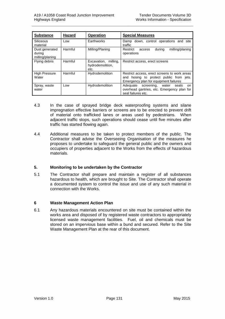
A19 / A1058 Coast Road Junction Improvement Tender Documents Volume 3D Highways England Works Information - Specification
Version 1.0 Page 131 May 2015
Substance Hazard Operation Special Measures Siliceous material
Low Earthworks Damp down, control operations and site traffic
Dust generated during milling/planing
Harmful Milling/Planing Restrict access during milling/planing operations
Flying debris Harmful Excavation, milling, hydrodemolition, etc.
Restrict access, erect screens
High Pressure Water
Harmful Hydrodemolition Restrict access, erect screens to work areas and hosing to protect public from jets. Emergency plan for equipment failures
Spray, waste water
Low Hydrodemolition Adequate screening, water seals on overhead gantries, etc. Emergency plan for seal failures etc.
4.3 In the case of sprayed bridge deck waterproofing systems and silane impregnation effective barriers or screens are to be erected to prevent drift of material onto trafficked lanes or areas used by pedestrians. When adjacent traffic stops, such operations should cease until five minutes after traffic has started flowing again.
4.4 Additional measures to be taken to protect members of the public. The
Contractor shall advise the Overseeing Organisation of the measures he proposes to undertake to safeguard the general public and the owners and occupiers of properties adjacent to the Works from the effects of hazardous materials.
5. Monitoring to be undertaken by the Contractor 5.1 The Contractor shall prepare and maintain a register of all substances
hazardous to health, which are brought to Site. The Contractor shall operate a documented system to control the issue and use of any such material in connection with the Works.
6 Waste Management Action Plan 6.1 Any hazardous materials encountered on site must be contained within the
works area and disposed of by registered waste contractors to appropriately licensed waste management facilities. Fuel, oil and chemicals must be stored on an impervious base within a bund and secured. Refer to the Site Waste Management Plan at the rear of this document.

A19 / A1058 Coast Road Junction Improvement Tender Documents Volume 3D Highways England Works Information - Specification
Version 1.0 Page 132 May 2015
APPENDIX 1/24: QUALITY MANAGEMENT SYSTEM 1. General 1.1 The Contractor shall institute and operate a quality management system
complying with BS EN ISO 9001 and Clause 104. The Quality Plan shall be submitted to the Project Manager for acceptance not later than twenty one days after award of the Contract.
1.2 The Contractor shall submit method statements etc. prior to commencement of any related work or activity and to a timetable included in the Quality Plan.
1.3 The Quality Plan shall include details on the following as a minimum:
(i) Contractor’s Organisation and Management.
a. Including the organisation of the contract, line command and communication links between parties involved in the Contract on and off Site.
b. Names, roles, responsibilities and authority of principals and key personnel.
(ii) Identification of the parts of the Contractor’s Quality Management System relevant to the Works.
(iii) Supply Chain Management
a. Including details of control and communications processes, assessment of the supplier’s and subcontractor’s quality management systems and quality control capabilities, monitoring arrangements, review and acceptance of work items being undertaken by the subcontractor or supplier.
b. Details and scheduling of Quality Plans required by relevant National Highways Sector Schemes or other quality management schemes.
c. Details of registration to relevant National Highway Sector Schemes or other quality management schemes.
(iv) Document Control
a. Controls relevant to the Works, including the control and processing of testing results, materials and workmanship certification and quality records
b. The management of quality records as required in sub-Clause 104.7
c. The control and scheduling of all documentation to be submitted to the Project Manager as required by the Specification throughout the Works.
(v) Resource Management
a. Including details of relevant skills and experience of personnel involved in the Works.
b. The relevant training and/or competency assessment certificates and/or registration/skills cards as required by sub-Clause 104.10 or scheduling of when they will be provided.

A19 / A1058 Coast Road Junction Improvement Tender Documents Volume 3D Highways England Works Information - Specification
Version 1.0 Page 133 May 2015
(vi) Method Statements
a. Method Statements for initial items of work and scheduling for all other method statements required.
b. This scheduling shall include times for submission of method statements such that they are submitted a minimum of fourteen days prior to the commencement of the relevant work.
(vii) Contractors Hold Points
a. points where no further work shall proceed without the written approval of a designated person of the Contractor’s management, who shall be named in the Quality Plan
(viii) Project Manager’s Hold Points
a. points where no further work shall proceed without the written approval of a designated representative of the Project Manager
2 Contractor’s Construction Quality Control
2.1 This section of the Quality Plan shall include:
(i) Statement of the Contractor’s organisation for quality control. The quality plan shall identify procedures (which may be a part of the Contractor’s general procedures) that cover the topics listed below. Copies of these procedures shall be made available to the Overseeing Organisation on request. These statements will normally be expected to include:
(a) the responsibility for the initiation and updating of the Quality Plan.
(b) responsibility of the ‘Management Representative’ for quality for monitoring compliance with it.
(c) responsibility for the adequacy of the quality records produced.]
(ii) Arrangements for ‘receiving’ and ‘in-process’ testing.
(iii) Control of test laboratories.
(iv) Control of test, measuring and inspection equipment.
(v) Document control. These controls should include their identification, traceability requirements, control of document issues and their status. They should also include the control of documents recording the verification review, approval, release and amendment of the works.]
(vi) Procedure for monitoring and recording the inspection, test and approval status of the constructed/installed work. [These should also identify ‘hold points’.]
(vii) Procedures for tests and inspections for the purpose of the Contractor certifying that prior to covering up, each part of the Works is complete and conforms to the Task Order documents. [These procedures should identify the proforma and/or database to be used for recording the inspection and test results, and the
A19 / A1058 Coast Road Junction Improvement Tender Documents Volume 3D Highways England Works Information - Specification
Version 1.0 Page 134 May 2015
proforma to be used for recording the certification of compliance of all items of the Works by authorised key personnel. Each submission should be separately identified.]
(viii) Procedure for the review of work submitted for review but not accepted as conforming to the Task Order documents. [These procedures should include options for identification of non-conforming work and proposals for reworking and remedial work.]
(ix) Procedure for the collation of quality records as identified in BS EN ISO 9001 and provision of copies when requested by the Overseeing Organisation. [Reference should be made to those records listed in the SHW Appendix H.]
3 Organisations' Quality Plans
3.1 The Quality Plan shall include:
(i) Definition of the product or service to be provided.
(ii) The organisation organogram shall describe the line of command and stating the name of the senior manager responsible for the contracted Work and the name of the Organisation’s on-site Management representative. Contact addresses, telephone numbers etc. shall be provided. [(11/03). An annotated chart is an effective means of illustrating the organisation structure. This must address all activities, including those sublet. Names of any subcontractors and organisations involved in the production shall be provided.]
(iii) *Identification of the relevant parts of the Organisation’s quality system relevant to the product or service being provided. (Copies to be provided to the Overseeing Organisation on request). [(11/03) It is important for the Overseeing Organization to be aware of the Organisation’s quality control procedures, in order to decide on its own level of inspection and testing.]
(v) The control of personnel selection (at works and on site), including special requirements for skilled personnel e.g. certification of welders, training of operatives, experience requirements etc. [(11/03) The Organizations shall provide evidence that the training and experience requirements given in the appropriate Quality Assessment Schedule are being met. CVs may be appropriate.]
5.2 Specific procedures for the following:
(i) *Receipt and examination of certificates of conformity and test results for purchased products.
(ii) *Product identification and traceability. [Each piece or bundle of delivered product shall be indelibly marked and where appropriate, the lot identification shall be included on each package.]
(iii) *Handling, storage, packaging and delivery to site and storage and handling on Site. [Instructions for repair of damaged products may be needed.]

A19 / A1058 Coast Road Junction Improvement Tender Documents Volume 3D Highways England Works Information - Specification
Version 1.0 Page 135 May 2015
(iv) Quality records. [These shall include documents to demonstrate, the achievement of the requirement standard, e.g. site logs, records of visits, records of verification, review and release, certificates of conformity and records of all design modifications to products and specifications.]
Items marked * where available and appropriate, copies of the Organisation’s quality system/general procedures may be acceptable.

A19 / A1058 Coast Road Junction Improvement Tender Documents Volume 3D Highways England Works Information - Specification
Version 1.0 Page 136 May 2015
APPENDIX 1/25: TEMPORARY CLOSED CIRCUIT TELEVISION (CCTV) SYSTEM FOR THE MONITORING OF TRAFFIC
1. Requirements for Temporary Closed Circuit Television (CCTV) system 1.1 The Contractor shall design, provide, install, maintain, operate and, at the
completion of the requirement, remove the temporary CCTV system as specified in this Appendix. The Contractor shall be responsible for obtaining any licences, power supplies and approvals required, including structural approvals, prior to the installation of any equipment.
1.2 The CCTV system shall operate 24 hours per day.
1.3 The system shall be designed such that the whole of the Works area is covered at all times. There shall be sufficient overlap between the areas covered by adjacent cameras such that there are no blind spots.
1.4 There is an existing CCTV system in operation on the existing A19, although only temporary. There is no CCTV system on the A1058 Coast Road. The Contractor shall ensure that any permanent CCTV systems on adjacent properties are not interfered with.
1.5 The Contractor shall provide, install, operate, maintain and, at the completion of the Works, remove a dedicated communication link to the Highways England Regional Control Centre.
A19 / A1058 Coast Road Junction Improvement Tender Documents Volume 3D Highways England Works Information - Specification
Version 1.0 Page 137 May 2015
APPENDIX 1/27: TEMPORARY AUTOMATIC SPEED CAMERA SYSTEM FOR THE ENFORCEMENT OF MANDATORY SPEED LIMITS AT ROADWORKS (TASCAR)
1. Speed Enforcement System 1.1 The Contractor shall design, supply, install and maintain a TASCAR system
for the enforcement of temporary mandatory speed limits on both the A19 and A1058 Coast Road.
1.2 The Contractor shall consult and comply with the requirements of the enforcing Authority.
1.3 The Contractor shall ensure that the system is fully operational from the time any such traffic management system comes into use and that it remains in operation for the duration of the Contract and is removed on completion of the works.
1.4 The Contractor shall arrange for the provision of a 240v AC single-phase mains electrical supply of adequate power capacity to all components of the system.
2. Location and Quantities 2.1 The Contractor shall submit his proposals for the number and location of
speed cameras to the Project Manager and the enforcing Authority for acceptance prior to installation.
2.2 Only speed measuring devices that have Home Office Type Approval (HOTA) shall be used. This also applies to installation poles and cabinets.
2.3 All lanes of the A19 and the A1058 Coast Road shall be monitored within the speed-controlled zone.
3. Enforcement Authority (EA) 3.1 The EA is Northumbria Police.
Address: Northumbria Police Force Headquarters
North Road, Ponteland
Newcastle upon Tyne, NE20 0BL
Tel: 101 ext: 69191
4. Installation Requirements 4.1 The Contractor shall install the poles in the individual speed monitoring
locations within the Site or the highway boundary as instructed by the Project Manager and shall carry out reinstatement of the ground as directed by and to the satisfaction of the Project Manager.
4.2 The Contractor shall ensure that suitable access arrangements are in place at each speed monitoring Site including vehicle hard standings, walkways and steps where necessary. The Contractor shall provide suitably located and accessible maintenance bays to allow for general maintenance and servicing of the camera unit.
4.3 The Contractor shall install the housing/poles in the positions specified, connect and commission the remainder of the equipment. The Contractor

A19 / A1058 Coast Road Junction Improvement Tender Documents Volume 3D Highways England Works Information - Specification
Version 1.0 Page 138 May 2015
shall ensure that the camera poles are located in accordance with the road restraint system requirements in TD 19 of the DMRB.
4.4 The Contractor shall ensure that the Site reference number is clearly indicated on both the installation and the road surface within the field of view of the camera. Site reference numbers shall be agreed with the EA.
4.5 Any ducting, loop or piezo installation shall be carried out in accordance with the relevant clauses of Series 500 and 1200 of the Specification.
5. Commissioning and Acceptance 5.1 The Contractor shall be responsible for the commissioning of the TASCAR
as a whole, including secondary checks. Details of equipment commissioning procedures will be provided to the Contractor from the supplier of the system. The Contractor shall provide a secondary method of confirming the speed calculation which is the approved method for the device used under HOTA. Each HOTA speed measuring device has a different approved secondary check method.
5.2 The commissioning of the TASCAR shall be carried out by the supplier of the system in the presence of, and for the acceptance of, the EA. The Contractor shall give the Project Manager not less than four days notice of his intention to carry out the work, to allow for a designated representative of the EA to attend. Commissioning certificates shall be provided to the Project Manager and shall include one pair of photographs or video images for acceptance by the EA as part of the commissioning and acceptance of the procedure of the system.
6. Operation and Maintenance 6.1 The TASCAR Operator will be the EA. Once the TASCAR has been
commissioned, the repositioning of the speed monitoring equipment between the housings, or switching of detection equipment between zones and servicing, will be the responsibility of the EA. The Contractor shall furnish whatever assistance is requested by the Operator through the Project Manager to carry out these tasks.
6.2 All evidential media from speed monitoring Sites will remain the property of the EA.
6.3 The Contractor shall provide the EA, through the Project Manager, with a two hourly log showing the locations of all the speed limit and speed limit repeater signs relative to existing marker posts. It is accepted that under certain conditions, i.e. a collision in the works, this task may not be able to be completed in the timescales given and where this occurs a record should be made on the log. A repeater sign shall be positioned such that one is visible in each photograph (Refer to Chapter 8 – Traffic Signs Manual). Where there is a 24-hour CCTV system installed that is monitoring ALL speed limit and repeater signs this log can be compiled remotely.

A19 / A1058 Coast Road Junction Improvement Tender Documents Volume 3D Highways England Works Information - Specification
Version 1.0 Page 139 May 2015
APPENDIX 1/70: LIST OF BUILDINGS TO BE SURVEYED 1.1 As a minimum, the Contractor shall arrange for condition surveys of the
properties described as being ‘affected by the scheme’, contained in Chapter 13 of the Environmental Statement. The surveys shall be undertaken within 14 days of the access date in agreement with Highways England. These include:
Table 1/70.1: List of Buildings to be surveyed
Reference Building / Structure
Police HQ
Silverdale School, Wallsend, Tyne and Wear
B&Q, Middle Engine Lane, Wallsend, Tyne and Wear NE28 9NT
McDonald's Tyneside Retail Park, Tyneside Retail Park,
Coast Road, North Shields, Tyne & Wear NE28 9ND
SCS, Silverlink Shopping Park, Silverlink Retail Park
Wallsend, NE28 9ND
Halfords, Unit H, Silverlink Retail Park, The Silverlink
Wallsend, Tyne and Wear, NE28 9ND
Regency Specialist Cars Ltd,
Vroom Car Retail Park Tyne Tunnel Trading Estate
North Shields, Vroom Car Retail Park
Newcastle upon Tyne, Tyne and Wear NE29 7SN
McDougal & Breen - Used Cars Newcastle
Vroom Car Retail Park, Orion Way, North Shields, NE29 7SN
Gosforth Park Motor Company Ltd
Unit 6, Orion Business Park, Vroom Car Retail Park
North Shields, Tyne and Wear, NE29 7SN
W D Motors, Orion Way, Orion Business Park, North Shields,
NE29 7SN
Northeastern Land Rover & 4x4 Specialists,
Unit 8 Vroom Car Retail Park, Tyne Tunnel Trading Estate
Vroom Car Retail Park, North Shields, Tyne and Wear, NE29 7TE

A19 / A1058 Coast Road Junction Improvement Tender Documents Volume 3D Highways England Works Information - Specification
Version 1.0 Page 140 May 2015
Table 1/70.1: List of Buildings to be surveyed Continued
Reference Building / Structure
Silverlink MG, Unit 7, Vroom Car Retail Park, North Shields,
Tyne and Wear, NE29 7SN
Hodgson Toyota Newcastle, The Silverlink, Wallsend,
Newcastle upon Tyne, Tyne and Wear, NE28 9ND
Richard Hardie Silverlink, Silverlink Retail Park,
Bittern Close, Wallsend, Tyne and Wear, NE28 9ND
North Eastern Tyre & Exhaust Ltd, Middle Engine Lane,
Wallsend, NE28 9NT
1.2 The Contractor shall arrange for further condition surveys to any additional properties identified during the works.
1.3 The Contractor shall arrange for a resurvey of the above properties prior to but not more than seven days before the issue of the Completion Certificate.
1.4 Surveys shall provide an independent, comprehensive structural assessment and condition survey. A comprehensive record of the condition of the garden / outdoor estate including sheds, garages and the like shall be made as well as the internal and external fabric of each residence.
1.5 The appointed surveyor shall be a fully qualified member or fellow of the Royal Institution of Chartered Surveyors (RICS).
1.6 Two copies of the condition survey report for each property shall be provided to the Project Manager within twenty eight days of the Site commencement date having obtained the agreement of the landowner that it is a fair and accurate assessment.

A19 / A1058 Coast Road Junction Improvement Tender Documents Volume 3D Highways England Works Information - Specification
Version 1.0 Page 141 May 2015
APPENDIX 2/1: LIST OF BUILDINGS, ETC, TO BE DEMOLISHED OR PARTIALLY DEMOLISHED
1. The items listed in Table 2/1.1 below shall be demolished or partially demolished as part of the Works.
Table 2/1.1: List of Buildings, etc. to be demolished
Address Description Drawing No. Ref No. Requirements
Vroom The Car Retail Park Orion Way Tyne Tunnel Trading Estate. North Shields, NE29 7SN
Car parking canopies
TBC TBC 7 No. canopy structures in car dealership car park to be demolished. Foundations to be removed and ground to be levelled.
2 General 2.1 All works in relation to Site Clearance shall be carried out in accordance with
Series 200 of the Specification for Highway Works (SHW).
2.2 Storage of any demolished material awaiting removal, recycling or relocation shall be entirely within the site boundary in designated areas within the Contractor’s Compounds, unless otherwise agreed with the Overseeing Organisation. A maximum height for stockpiles will be agreed with the Overseeing Organisation. Reference to the Site Waste Management Plan and Construction Environmental Management Plan shall be made prior to the removal for recycling or disposal of any demolished material.
2.3 The foundations of superficial obstructions that are subject to general site clearance including safety barriers, lighting columns, sign posts, etc., shall be removed down to formation level.
2.4 The Contractor shall give consideration to the site clearance of road restraint systems to ensure that its untimely removal does not create hazards to road users.
2.5 Voids left by the removal of equipment otherwise unaffected by the permanent works shall be backfilled immediately in accordance with Series 600 of the Specification for Highway Works. Where appropriate the upper reinstatement shall match the existing or proposed construction.
2.6 The Contractor shall take account of the guidance given in the Pollution Prevention Guidelines and Statements issued by the Environment Agency where these relate to construction works. In particular the Contractor shall note PPG1 General Guide to the Prevention of Pollution, PPG2 Above Ground Oil Storage Tanks, PPG 5 Works in, near to, or Liable to Affect Watercourses, PPG06 Working at Demolition & Construction Sites, PPG18 Dewatering Underground Ducts and Chambers, and PPG 22 Dealing with Spillages on Highways.
2.7 All existing drainage within the Site shall be maintained and/or temporary

A19 / A1058 Coast Road Junction Improvement Tender Documents Volume 3D Highways England Works Information - Specification
Version 1.0 Page 142 May 2015
drainage systems used until the new permanent drainage is installed and functioning satisfactorily. Any temporary drainage systems used shall ensure that the drainage of the carriageway is not impaired.
2.8 All existing traffic signs within the Site shall be maintained or temporary signs used until the new permanent signs are installed and functioning satisfactorily.
2.9 The Contractor will develop the Site Waste Management Plan. This will include a waste flow analysis which identifies the generation volumes, nature, and timing of all waste generated during construction, including hazardous waste. The Contractor shall liaise with the Environment Agency to agree acceptable measures for the tracking, handling, storage, and disposal of hazardous material found in the course of site clearance.
2.10 Below are relevant details relating to the Site Waste Management Plan:
(i) The Contractor will refer to the Site Waste Management Plan and manage all Site Clearance Waste arisings in line with the requirements and procedures set out in the Plan unless otherwise agreed with the Overseeing Organisation.
(ii) Site Clearance Waste (hereon referred to as ‘Waste’) is defined as any materials or items to be removed, cleared, or demolished as part of the Site Clearance works as described in this Appendix.
(iii) The Contractor will manage Waste arisings in line with the Waste Management Duty of Care Code of Practice for Controlled Waste (as issued by the Secretary of State for the Environment in accordance with section 34(7) and (8) of the Environmental Protection Act 1990).
(iv) All Waste awaiting further handling, including removal, relocation, reuse, reprocessing, recycling, treatment or disposal must be stored within the site boundary in designated areas within the Contractor’s compound unless otherwise agreed with the Overseeing Organisation.
2.11 The Contractor shall comply with the Waste monitoring and reporting procedures set out in the Plan and performance will be externally assessed against the objectives and indicative targets set out in the Plan. If necessary the Contractor may be required to review and revise the works waste management plan to remedy any deviation from the Plan, where this is deemed to be an unreasonable departure from the Plan by the external assessor, taking into account the project programme and constraints.
2.12 Construction Environmental Management Plan - Prior to any works commencing on site, a Construction Environmental Management Plan shall be submitted to and approved in writing by the Overseeing Organisation. Thereafter the works shall be carried out entirely in accordance with the approved plan, unless otherwise agreed in advance in writing with the Overseeing Organisation.

A19 / A1058 Coast Road Junction Improvement Tender Documents Volume 3D Highways England Works Information - Specification
Version 1.0 Page 143 May 2015
3 Vegetation Clearance 3.1 Prior to the commencement of any site clearance, details of best practice
guidance and a methodology for the proposed removal of existing planting and the of protection of existing planting at the site to be retained during the proposed development shall be submitted to and approved by the Overseeing Organisation. Thereafter, the proposed works shall be carried out in accordance with the approved details.
3.2 Vegetation clearance shall be limited to that necessary to carry out the works.
3.3 The boundaries of site clearance actives shall be agreed between the Contractor and Overseeing Organisation so as to minimise the removal of existing vegetation.
3.4 No trees shall be removed, pruned, lopped, or otherwise disturbed without the approval of the Overseeing Organisation.
3.5 All retained onsite vegetation and vulnerable offsite vegetation overhanging the site boundary or with root zones within the Site shall be protected from damage to root, stem, and crown.
3.6 Site clearance of vegetation shall be undertaken outside the breeding season for birds (i.e. beginning of March to end of September) such that no nest in use or being built will be disturbed, and in accordance with the interests of other habitats, flora and fauna unless otherwise agreed with the Overseeing Organisation. Where this cannot be achieved, a suitably experienced ecologist shall inspect all vegetation which holds potential for nesting birds prior to its removal.

A19 / A1058 Coast Road Junction Improvement Tender Documents Volume 3D Highways England Works Information - Specification
Version 1.0 Page 144 May 2015
APPENDIX 2/2: FILLING OF TRENCHES AND PIPES 1. The Contractor shall comply with the requirements of Clause 201.4 when
filling of trenches and pipes shall be required.
2 Any drainage found within 1 metre of formation which is not shown to be removed on the drawings to be notified to the Overseeing Organisation.
3 Unless otherwise noted on the Site Clearance Drawings, disused surface water drains, sewers, cables and ducts together with any bed or haunch or surround shall be treated in accordance with Clause 201.4 of the Specification for Highway Works.
4 The Contractor shall take all measures required by any Statutory Undertaker, or owners/ managers of privately/ publicly owned services or suppliers for the support, protection, backfilling and compaction of materials below, adjacent to and above Statutory Undertakers apparatus whether exposed or buried.
5 All voids resultant from the Works within areas accessible to the public shall be backfilled immediately.
6 Exposed ends of pipes / ducts severed by the Works shall be sealed with ST1 concrete to Clause 2602 of the Specification for Highway Works and where ferrous shall also be coated with two coats of cutback bitumen.
7 All abandoned gullies shall be excavated and back filled up to sub-formation
level with ST1 concrete to Clause 2602 of the Specification for Highway Works. Ends of exposed pipes shall be sealed with ST1 concrete and where ferrous shall be coated with two coats of cutback bitumen.

A19 / A1058 Coast Road Junction Improvement Tender Documents Volume 3D Highways England Works Information - Specification
Version 1.0 Page 145 May 2015
APPENDIX 2/3: RETENTION OF MATERIAL ARISING FROM SITE CLEARANCE
1 The materials arising from Site listed in the table below shall be retained.
Table 2/3.1: List of materials to be retained
Description Location Delivered to: Requirements
Road studs A19 and A1098 Project Managers Store
Steel housings only
Pedestrian Guardrailing
A19 and A1098 Project Managers Store
2 Statutory Undertakers apparatus which is made redundant by the Works and requires removal for the construction of the works shall be dealt with in a manner which the Contractor shall agree with the relevant Statutory Undertaker.
3 All signs not scheduled for replacement shall remain undisturbed during Site Clearance where possible or re-set at completion of works.
4 All drainage/ ducting covers, frames and gratings not scheduled for replacement/ relocation are to remain undisturbed during Site Clearance where possible or re-set on completion of works.
5 All materials to be taken up or down and set aside for reuse as part of the works shall be taken to the Contractor’s Store.
6 The Contractor should note that the burning of material arising from the Site is not permitted.
7 All materials arising from site clearance activities shall be disposed of in accordance with the Contractor’s Waste Management Plan

A19 / A1058 Coast Road Junction Improvement Tender Documents Volume 3D Highways England Works Information - Specification
Version 1.0 Page 146 May 2015
APPENDIX 2/4: EXPLOSIVES AND BLASTING 1. The Contractor’s attention is drawn to the measures for the control of noise
and vibration which are included in Appendix 1/9.
2. Explosives shall not be used unless prior consent in writing shall have been given by the Project Manager and subject to the stated conditions.

A19 / A1058 Coast Road Junction Improvement Tender Documents Volume 3D Highways England Works Information - Specification
Version 1.0 Page 147 May 2015
APPENDIX 2/5: HAZARDOUS MATERIALS 1. The Contractor shall consult and comply with the requirements of the
relevant Authorities for the handling and disposal of hazardous material found in Site clearance.
2. In the event of hazardous material being found during Site clearance, the Contractor shall employ suitably qualified personnel to undertake a full ground contamination survey and report, as required by any relevant Authority.
3 The Contractor will develop a Site Waste Management Plan. This will include a waste flow analysis which identifies the generation volumes, nature, and timing of all waste generated during construction, including hazardous waste. The Contractor shall liaise with the Environment Agency to agree acceptable measures for the tracking, handling, storage, and disposal of hazardous material found in the course of site clearance.
4 The Contractor is responsible for the identification and classification of materials which may require on site remediation/recycling and off-site disposal at an appropriately licensed tip capable of accepting such materials. In addition the Contractor shall be responsible for carrying out any supplementary WAC/chemical testing which may be necessary to aid the classification of any waste materials encountered during site clearance operations.
5 Any hazardous materials which require off-site disposal shall be transported from site by a waste carrier registered under the Controlled Waste (Registration of Carriers Seizure of Vehicles) (Amendment) Regulation 1998. The Contractor and his carrier will be subject to Section 34 (Duty of Care) of the Environmental Prosecution Act 1990 and Special Waste (Amendment) Regulations 2001 and shall complete descriptions of the waste removed using a Transfer Note or Special Waste Consignment Note as appropriate. For the avoidance of doubt, all waste materials will be managed using a consignment note system, even where these are recycled or reused on site.
6 The Contractor shall comply with the requirements given in the Health and Safety Plan and Appendix 1/23 for a specific procedure to ensure that if asbestos is encountered or suspected the ‘Control of Asbestos at Work Regulation’ and all other Mandatory Regulations are complied with.
7 The Contractor shall fully comply with all Legislation and Regulations detailed above as well as all other current Environmental Legislation/Regulations during the works.
8 All bituminous materials excavated, which cannot be reused within the Works, shall be removed off site to a suitable licensed landfill. This transfer will require some form of pre-treatment prior to disposal.
9 Treatment of any other hazardous material, if encountered in the Works, shall be agreed with the Overseeing Organisation and comply with the current COSHH Regulations.

A19 / A1058 Coast Road Junction Improvement Tender Documents Volume 3D Highways England Works Information - Specification
Version 1.0 Page 148 May 2015
APPENDIX 3/1: FENCING, GATES AND STILES 1 Temporary Fencing 1.1 The Contractor shall comply with the requirements of Clause 302 and 303 of
the specification for Highway Works.
2 Timber Quality 2.1 The Contractor shall comply with the requirements of Clause 304 of the
Specification for Highways Works.
3 Fittings 3.1 The Contractor shall comply with the requirements of Clause 305 of the
Specification for Highways Works.
4 Permanent Fencing: Wooden Fencing, Gates and Stiles including Planting Works Fencing
4.1 The Contractor shall comply with the requirements of Clause 306 of the Specification for Highways Works.
5 Permanent Fencing: Wire Dropper Fencing 5.1 The Contractor shall comply with the requirements of Clause 306 of the
Specification for Highways Works.
6 Preservation of Timber 6.1 The Contractor shall comply with the requirements of Clause 311 of the
Specification for Highways Works.

A19 / A1058 Coast Road Junction Improvement Tender Documents Volume 3D Highways England Works Information - Specification
Version 1.0 Page 149 May 2015
APPENDIX 4/1: ROAD RESTRAINTSYSTEMS (VEHICLE AND PEDESTRIAN)
1 Location: 1.1 Vehicle Restraint Systems
(i) The location, Containment Level, Impact Severity Level (ISL), Working Width Class, maximum height that allows the required visibility and the Length of Need requirements for safety barriers and transitions are shown on Drawing Nos. A19T-DWG-CIV-400-0000-0001 to 0007 inclusive.
(ii) The location, Containment Level, Impact Severity Level (ISL), and Working Width Class requirements for vehicle parapets are shown on Drawing Nos. A19T-DWG-CIV-400-0000-0001 to 0007 inclusive.
(iii) The location, Performance Class, Impact Severity Level (ISL), Permanent Lateral Displacement Zone (PLDZ) Characteristic, Exit Box Class (D), and maximum height that allows the required visibility requirements for terminals are shown on Drawing Nos. A19T-DWG-CIV-400-0000-0001 to 0007 inclusive.
1.2 Pedestrian Restraint Systems (i) The location for pedestrian parapets and pedestrian guardrails are
shown on Drawing Nos. A19T-DWG-CIV-400-0000-0001 to 0007 inclusive.
2 Other Details: Safety Barriers, Terminals, Transitions and Crash Cushions
2.1 The Contractor shall comply with the requirements of Clauses 401, 402 and 403 of the Specification for Highways Works.
Vehicle Parapets Including Anchorages and Attachment Systems 2.2 The Contractor shall comply with the requirements of Clauses 401 and 406
of the Specification of Highway Works.
3 Testing [Cross - reference with Appendix 1/5 as appropriate] Destructive Testing
3.1 The Contractor shall provide copies of certified reports of destructive tests as required by Clauses 402.6(v) and 408 of the Specification for Highway Works before any such item is installed in the Works.
Site Testing on Post Foundations 3.2 The Contractor shall comply with the requirements for Site load tests on
safety barrier, terminal and transition post foundations in accordance with Clause 404 of the Specification for Highway Works.
Inspection and Testing of Vehicle Parapet Posts 3.3 The Contractor shall comply with the requirements of Clause 409 of the
Specification for Highways Works.
Site Testing on Anchorages in Drilled Holes 3.5 The Contractor shall comply with the requirements of Clause 404 and 410 of
the Specification for Highways Works.
A19 / A1058 Coast Road Junction Improvement Tender Documents Volume 3D Highways England Works Information - Specification
Version 1.0 Page 150 May 2015
4 Temporary Safety Barriers 4.1 The Contractor shall provide, install and maintain temporary safety barriers,
terminals and transitions, and on completion of the Works, remove them from Site in accordance with his Traffic Safety and Management proposals.
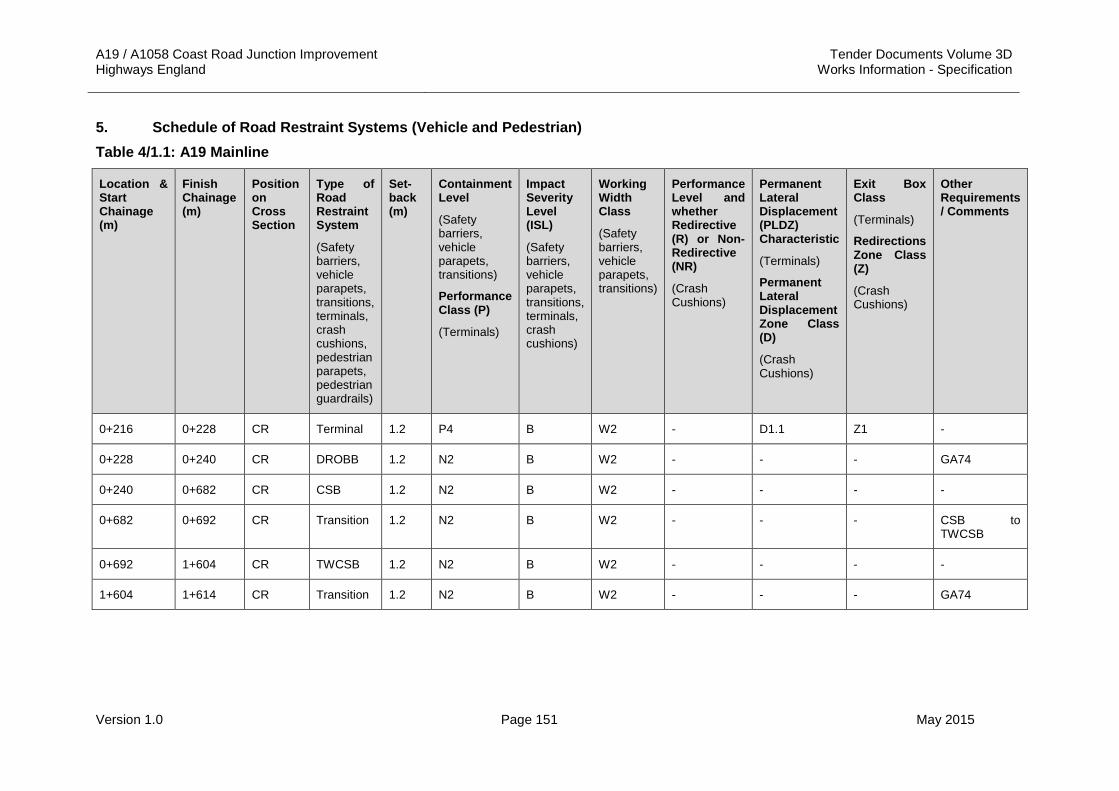
A19 / A1058 Coast Road Junction Improvement Tender Documents Volume 3D Highways England Works Information - Specification
Version 1.0 Page 151 May 2015
5. Schedule of Road Restraint Systems (Vehicle and Pedestrian) Table 4/1.1: A19 Mainline
Location & Start Chainage (m)
Finish Chainage (m)
Position on Cross Section
Type of Road Restraint System
(Safety barriers, vehicle parapets, transitions, terminals, crash cushions, pedestrian parapets, pedestrian guardrails)
Set-back (m)
Containment Level
(Safety barriers, vehicle parapets, transitions)
Performance Class (P)
(Terminals)
Impact Severity Level (ISL)
(Safety barriers, vehicle parapets, transitions, terminals, crash cushions)
Working Width Class
(Safety barriers, vehicle parapets, transitions)
Performance Level and whether Redirective (R) or Non-Redirective (NR)
(Crash Cushions)
Permanent Lateral Displacement (PLDZ) Characteristic
(Terminals)
Permanent Lateral Displacement Zone Class (D)
(Crash Cushions)
Exit Box Class
(Terminals)
Redirections Zone Class (Z)
(Crash Cushions)
Other Requirements / Comments
0+216 0+228 CR Terminal 1.2 P4 B W2 - D1.1 Z1 -
0+228 0+240 CR DROBB 1.2 N2 B W2 - - - GA74
0+240 0+682 CR CSB 1.2 N2 B W2 - - - -
0+682 0+692 CR Transition 1.2 N2 B W2 - - - CSB to TWCSB
0+692 1+604 CR TWCSB 1.2 N2 B W2 - - - -
1+604 1+614 CR Transition 1.2 N2 B W2 - - - GA74

A19 / A1058 Coast Road Junction Improvement Tender Documents Volume 3D Highways England Works Information - Specification
Version 1.0 Page 152 May 2015
Table 4/1.1: A19 Mainline Continued
Location & Start Chainage (m)
Finish Chainage (m)
Position on Cross Section
Type of Road Restraint System
(Safety barriers, vehicle parapets, transitions, terminals, crash cushions, pedestrian parapets, pedestrian guardrails)
Set-back (m)
Containment Level
(Safety barriers, vehicle parapets, transitions)
Performance Class (P)
(Terminals)
Impact Severity Level (ISL)
(Safety barriers, vehicle parapets, transitions, terminals, crash cushions)
Working Width Class
(Safety barriers, vehicle parapets, transitions)
Performance Level and whether Redirective (R) or Non-Redirective (NR)
(Crash Cushions)
Permanent Lateral Displacement (PLDZ) Characteristic
(Terminals)
Permanent Lateral Displacement Zone Class (D)
(Crash Cushions)
Exit Box Class
(Terminals)
Redirections Zone Class (Z)
(Crash Cushions)
Other Requirements / Comments
1+614 1+625 CR DROBB 1.2 N2 B W2 - - - -
1+625 1+627 CR Transition 1.2 N2 B W2 - - - -
1+627 1+896 CR Safety Barrier
1.2 N2 B W2 - - - -
1+896 1+941 CR Safety Barrier
1.2 N2 B W2 - - - -

A19 / A1058 Coast Road Junction Improvement Tender Documents Volume 3D Highways England Works Information - Specification
Version 1.0 Page 153 May 2015
Table 4/1.1: A19 Mainline Continued
Location & Start Chainage (m)
Finish Chainage (m)
Position on Cross Section
Type of Road Restraint System
(Safety barriers, vehicle parapets, transitions, terminals, crash cushions, pedestrian parapets, pedestrian guardrails)
Set-back (m)
Containment Level
(Safety barriers, vehicle parapets, transitions)
Performance Class (P)
(Terminals)
Impact Severity Level (ISL)
(Safety barriers, vehicle parapets, transitions, terminals, crash cushions)
Working Width Class
(Safety barriers, vehicle parapets, transitions)
Performance Level and whether Redirective (R) or Non-Redirective (NR)
(Crash Cushions)
Permanent Lateral Displacement (PLDZ) Characteristic
(Terminals)
Permanent Lateral Displacement Zone Class (D)
(Crash Cushions)
Exit Box Class
(Terminals)
Redirections Zone Class (Z)
(Crash Cushions)
Other Requirements / Comments
1+941 1+961 CR Transition 1.2 N2 B W5 - - - N2 W2 Safety Barrier to connect into existing N2 W5 Safety Barrier
1+030 1+040 LHV End Terminal
0.6 P4 B W2 - D1.2 Z2 -
1+040 1+060 LHV Safety Barrier
0.6 N2 B W2 - - - -
1+060 1+072 LHV Transition 0.6 N2 B W2 - - - -

A19 / A1058 Coast Road Junction Improvement Tender Documents Volume 3D Highways England Works Information - Specification
Version 1.0 Page 154 May 2015
Table 4/1.1: A19 Mainline
Location & Start Chainage (m)
Finish Chainage (m)
Position on Cross Section
Type of Road Restraint System
(Safety barriers, vehicle parapets, transitions, terminals, crash cushions, pedestrian parapets, pedestrian guardrails)
Set-back (m)
Containment Level
(Safety barriers, vehicle parapets, transitions)
Performance Class (P)
(Terminals)
Impact Severity Level (ISL)
(Safety barriers, vehicle parapets, transitions, terminals, crash cushions)
Working Width Class
(Safety barriers, vehicle parapets, transitions)
Performance Level and whether Redirective (R) or Non-Redirective (NR)
(Crash Cushions)
Permanent Lateral Displacement (PLDZ) Characteristic
(Terminals)
Permanent Lateral Displacement Zone Class (D)
(Crash Cushions)
Exit Box Class
(Terminals)
Redirections Zone Class (Z)
(Crash Cushions)
Other Requirements / Comments
1+072 1+118 LHV Pedestrian Parapet
0.6 - - - - - - -
1+269 1+361 LHV Pedestrian Parapet
0.6 - - - - - - -
1+587 1+597 LHV Terminal 0.6 P4 B W4 - D1.2 Z2 -
1+597 1+627 LHV Safety Barrier
0.6 N2 B W4 - - - -
1+627 1+666 LHV Vehicle Parapet
0.6 N2 B W4 - - - -

A19 / A1058 Coast Road Junction Improvement Tender Documents Volume 3D Highways England Works Information - Specification
Version 1.0 Page 155 May 2015
Table 4/1.1: A19 Mainline Continued
Location & Start Chainage (m)
Finish Chainage (m)
Position on Cross Section
Type of Road Restraint System
(Safety barriers, vehicle parapets, transitions, terminals, crash cushions, pedestrian parapets, pedestrian guardrails)
Set-back (m)
Containment Level
(Safety barriers, vehicle parapets, transitions)
Performance Class (P)
(Terminals)
Impact Severity Level (ISL)
(Safety barriers, vehicle parapets, transitions, terminals, crash cushions)
Working Width Class
(Safety barriers, vehicle parapets, transitions)
Performance Level and whether Redirective (R) or Non-Redirective (NR)
(Crash Cushions)
Permanent Lateral Displacement (PLDZ) Characteristic
(Terminals)
Permanent Lateral Displacement Zone Class (D)
(Crash Cushions)
Exit Box Class
(Terminals)
Redirections Zone Class (Z)
(Crash Cushions)
Other Requirements / Comments
1+666 1+709 LHV Transition 0.6 N2 B W4 - - - Connects to existing N2 W5 steel barrier
0+210 0+222 RHV Terminal 0.6 P1 B W2 - D1.2 Z2 -
0+222 0+262.5 RHV Safety Barrier
0.6 H1 B W2 - - - -
0+262.5 0+274.5 RHV Terminal 0.6 P4 B W2 - D1.2 Z2 -
0+822 0+834 RHV Terminal 0.6 P1 B W2 - D1.2 Z2 -

A19 / A1058 Coast Road Junction Improvement Tender Documents Volume 3D Highways England Works Information - Specification
Version 1.0 Page 156 May 2015
Table 4/1.1: A19 Mainline Continued
Location & Start Chainage (m)
Finish Chainage (m)
Position on Cross Section
Type of Road Restraint System
(Safety barriers, vehicle parapets, transitions, terminals, crash cushions, pedestrian parapets, pedestrian guardrails)
Set-back (m)
Containment Level
(Safety barriers, vehicle parapets, transitions)
Performance Class (P)
(Terminals)
Impact Severity Level (ISL)
(Safety barriers, vehicle parapets, transitions, terminals, crash cushions)
Working Width Class
(Safety barriers, vehicle parapets, transitions)
Performance Level and whether Redirective (R) or Non-Redirective (NR)
(Crash Cushions)
Permanent Lateral Displacement (PLDZ) Characteristic
(Terminals)
Permanent Lateral Displacement Zone Class (D)
(Crash Cushions)
Exit Box Class
(Terminals)
Redirections Zone Class (Z)
(Crash Cushions)
Other Requirements / Comments
0+834 0+874.5 RHV Safety Barrier
0.6 H1 B W2 - - - -
0+874.5 0+886.5 RHV Terminal 0.6 P4 B W2 - D1.2 Z2 -
1+000 1+110 RHV Pedestrian Parapet
0.6 - - - - - - -
1+282 1+397 RHV Pedestrian Parapet
0.6 - - - - - - -
1+397 1+409 RHV Transition 0.6 N2 B W2 - - - -

A19 / A1058 Coast Road Junction Improvement Tender Documents Volume 3D Highways England Works Information - Specification
Version 1.0 Page 157 May 2015
Table 4/1.1: A19 Mainline Continued
Location & Start Chainage (m)
Finish Chainage (m)
Position on Cross Section
Type of Road Restraint System
(Safety barriers, vehicle parapets, transitions, terminals, crash cushions, pedestrian parapets, pedestrian guardrails)
Set-back (m)
Containment Level
(Safety barriers, vehicle parapets, transitions)
Performance Class (P)
(Terminals)
Impact Severity Level (ISL)
(Safety barriers, vehicle parapets, transitions, terminals, crash cushions)
Working Width Class
(Safety barriers, vehicle parapets, transitions)
Performance Level and whether Redirective (R) or Non-Redirective (NR)
(Crash Cushions)
Permanent Lateral Displacement (PLDZ) Characteristic
(Terminals)
Permanent Lateral Displacement Zone Class (D)
(Crash Cushions)
Exit Box Class
(Terminals)
Redirections Zone Class (Z)
(Crash Cushions)
Other Requirements / Comments
1+409 1+427 RHV Safety Barrier
0.6 N2 B W2 - - - -
1+427 1+439 RHV Terminal 0.6 P4 B W2 - D1.2 Z2 -

A19 / A1058 Coast Road Junction Improvement Tender Documents Volume 3D Highways England Works Information - Specification
Version 1.0 Page 158 May 2015
Table 4/1.2: Northbound Diverge Slip Road
Location & Start Chainage (m)
Finish Chainage (m)
Position on Cross Section
Type of Road Restraint System
(Safety barriers, vehicle parapets, transitions, terminals, crash cushions, pedestrian parapets, pedestrian guardrails)
Set-back (m)
Containment Level
(Safety barriers, vehicle parapets, transitions)
Performance Class (P)
(Terminals)
Impact Severity Level (ISL)
(Safety barriers, vehicle parapets, transitions, terminals, crash cushions)
Working Width Class
(Safety barriers, vehicle parapets, transitions)
Performance Level and whether Redirective (R) or Non-Redirective (NR)
(Crash Cushions)
Permanent Lateral Displacement (PLDZ) Characteristic
(Terminals)
Permanent Lateral Displacement Zone Class (D)
(Crash Cushions)
Exit Box Class
(Terminals)
Redirections Zone Class (Z)
(Crash Cushions)
Other Requirements / Comments
0+391 0+403 RHV Terminal 0.6 P4 B W2 - D1.2 Z2 -
0+403 0+508 RHV Safety Barrier
0.6 N2 B W2 - - - -
0+508 0+520 RHV Terminal 0.6 P1 B W2 - D1.2 Z2 -

A19 / A1058 Coast Road Junction Improvement Tender Documents Volume 3D Highways England Works Information - Specification
Version 1.0 Page 159 May 2015
Table 4/1.3: Northbound Merge Slip Road
Location & Start Chainage (m)
Finish Chainage (m)
Position on Cross Section
Type of Road Restraint System
(Safety barriers, vehicle parapets, transitions, terminals, crash cushions, pedestrian parapets, pedestrian guardrails)
Set-back (m)
Containment Level
(Safety barriers, vehicle parapets, transitions)
Performance Class (P)
(Terminals)
Impact Severity Level (ISL)
(Safety barriers, vehicle parapets, transitions, terminals, crash cushions)
Working Width Class
(Safety barriers, vehicle parapets, transitions)
Performance Level and whether Redirective (R) or Non-Redirective (NR)
(Crash Cushions)
Permanent Lateral Displacement (PLDZ) Characteristic
(Terminals)
Permanent Lateral Displacement Zone Class (D)
(Crash Cushions)
Exit Box Class
(Terminals)
Redirections Zone Class (Z)
(Crash Cushions)
Other Requirements / Comments
0+015 0+027 RHV Terminal 0.6 P4 B W2 - D1.2 Z2 -
0+027 0+122.5 RHV Safety Barrier
0.6 N2 B W2 - - - -
0+122.5 0+134.5 RHV Terminal 0.6 P1 B W2 - D1.2 Z2 -
0+030 0+170 LHV Pedestrian Parapet
0.6 - - - - - - -
0+327 0+339 LHV Terminal 0.6 P4 B W4 - D1.2 Z2 -
0+339 0+369 LHV Safety Barrier
0.6 N2 B W4 - - - -

A19 / A1058 Coast Road Junction Improvement Tender Documents Volume 3D Highways England Works Information - Specification
Version 1.0 Page 160 May 2015
Table 4/1.3: Northbound Merge Slip Road Continued
Location & Start Chainage (m)
Finish Chainage (m)
Position on Cross Section
Type of Road Restraint System
(Safety barriers, vehicle parapets, transitions, terminals, crash cushions, pedestrian parapets, pedestrian guardrails)
Set-back (m)
Containment Level
(Safety barriers, vehicle parapets, transitions)
Performance Class (P)
(Terminals)
Impact Severity Level (ISL)
(Safety barriers, vehicle parapets, transitions, terminals, crash cushions)
Working Width Class
(Safety barriers, vehicle parapets, transitions)
Performance Level and whether Redirective (R) or Non-Redirective (NR)
(Crash Cushions)
Permanent Lateral Displacement (PLDZ) Characteristic
(Terminals)
Permanent Lateral Displacement Zone Class (D)
(Crash Cushions)
Exit Box Class
(Terminals)
Redirections Zone Class (Z)
(Crash Cushions)
Other Requirements / Comments
0+369 0+408 LHV Vehicle Parapet
0.6 N2 B W4 - - - -
0+408 0+440 LHV Transition 0.6 N2 B W4 to W5 - - - Connect to existing safety barrier
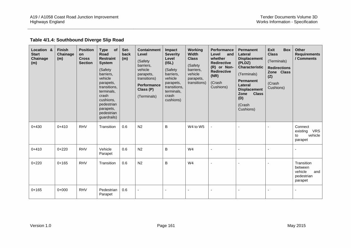
A19 / A1058 Coast Road Junction Improvement Tender Documents Volume 3D Highways England Works Information - Specification
Version 1.0 Page 161 May 2015
Table 4/1.4: Southbound Diverge Slip Road
Location & Start Chainage (m)
Finish Chainage (m)
Position on Cross Section
Type of Road Restraint System
(Safety barriers, vehicle parapets, transitions, terminals, crash cushions, pedestrian parapets, pedestrian guardrails)
Set-back (m)
Containment Level
(Safety barriers, vehicle parapets, transitions)
Performance Class (P)
(Terminals)
Impact Severity Level (ISL)
(Safety barriers, vehicle parapets, transitions, terminals, crash cushions)
Working Width Class
(Safety barriers, vehicle parapets, transitions)
Performance Level and whether Redirective (R) or Non-Redirective (NR)
(Crash Cushions)
Permanent Lateral Displacement (PLDZ) Characteristic
(Terminals)
Permanent Lateral Displacement Zone Class (D)
(Crash Cushions)
Exit Box Class
(Terminals)
Redirections Zone Class (Z)
(Crash Cushions)
Other Requirements / Comments
0+430 0+410 RHV Transition 0.6 N2 B W4 to W5 - - - Connect existing VRS to vehicle parapet
0+410 0+220 RHV Vehicle Parapet
0.6 N2 B W4 - - - -
0+220 0+165 RHV Transition 0.6 N2 B W4 - - - Transition between vehicle and pedestrian parapet
0+165 0+000 RHV Pedestrian Parapet
0.6 - - - - - - -

A19 / A1058 Coast Road Junction Improvement Tender Documents Volume 3D Highways England Works Information - Specification
Version 1.0 Page 162 May 2015
Table 4/1.4: Southbound Diverge Slip Road Continued
Location & Start Chainage (m)
Finish Chainage (m)
Position on Cross Section
Type of Road Restraint System
(Safety barriers, vehicle parapets, transitions, terminals, crash cushions, pedestrian parapets, pedestrian guardrails)
Set-back (m)
Containment Level
(Safety barriers, vehicle parapets, transitions)
Performance Class (P)
(Terminals)
Impact Severity Level (ISL)
(Safety barriers, vehicle parapets, transitions, terminals, crash cushions)
Working Width Class
(Safety barriers, vehicle parapets, transitions)
Performance Level and whether Redirective (R) or Non-Redirective (NR)
(Crash Cushions)
Permanent Lateral Displacement (PLDZ) Characteristic
(Terminals)
Permanent Lateral Displacement Zone Class (D)
(Crash Cushions)
Exit Box Class
(Terminals)
Redirections Zone Class (Z)
(Crash Cushions)
Other Requirements / Comments
0+172 0+160 LHV Terminal 0.6 P4 B W2 - D1.2 Z2 -
0+160 0+012 LHV Safety Barrier
0.6 N2 B W2 - - - -
0+012 0+000 LHV Terminal 0.6 P1 B W2 - D1.2 Z2 -

A19 / A1058 Coast Road Junction Improvement Tender Documents Volume 3D Highways England Works Information - Specification
Version 1.0 Page 163 May 2015
Table 4/1.5: Southbound Merge Slip Road
Location & Start Chainage (m)
Finish Chainage (m)
Position on Cross Section
Type of Road Restraint System
(Safety barriers, vehicle parapets, transitions, terminals, crash cushions, pedestrian parapets, pedestrian guardrails)
Set-back (m)
Containment Level
(Safety barriers, vehicle parapets, transitions)
Performance Class (P)
(Terminals)
Impact Severity Level (ISL)
(Safety barriers, vehicle parapets, transitions, terminals, crash cushions)
Working Width Class
(Safety barriers, vehicle parapets, transitions)
Performance Level and whether Redirective (R) or Non-Redirective (NR)
(Crash Cushions)
Permanent Lateral Displacement (PLDZ) Characteristic
(Terminals)
Permanent Lateral Displacement Zone Class (D)
(Crash Cushions)
Exit Box Class
(Terminals)
Redirections Zone Class (Z)
(Crash Cushions)
Other Requirements / Comments
0+190 0+178 LHV Terminal 0.6 P4 B W2 - D1.2 Z2 -
0+178 0+143 LHV Safety Barrier
0.6 N2 B W2 - - - -
0+143 0+131 LHV Terminal 0.6 P1 B W2 - D1.2 Z2 -

A19 / A1058 Coast Road Junction Improvement Tender Documents Volume 3D Highways England Works Information - Specification
Version 1.0 Page 164 May 2015
Table 4/1.6: Silverlink Roundabout
Location & Start Chainage (m)
Finish Chainage (m)
Position on Cross Section
Type of Road Restraint System
(Safety barriers, vehicle parapets, transitions, terminals, crash cushions, pedestrian parapets, pedestrian guardrails)
Set-back (m)
Containment Level
(Safety barriers, vehicle parapets, transitions)
Performance Class (P)
(Terminals)
Impact Severity Level (ISL)
(Safety barriers, vehicle parapets, transitions, terminals, crash cushions)
Working Width Class
(Safety barriers, vehicle parapets, transitions)
Performance Level and whether Redirective (R) or Non-Redirective (NR)
(Crash Cushions)
Permanent Lateral Displacement (PLDZ) Characteristic
(Terminals)
Permanent Lateral Displacement Zone Class (D)
(Crash Cushions)
Exit Box Class
(Terminals)
Redirections Zone Class (Z)
(Crash Cushions)
Other Requirements / Comments
0+122 0+134 RHV Terminal 3.6 P4 B W2 - D1.2 Z2 -
0+134 0+167 RHV Safety barrier
3.6 N2 B W2 - - - -
0+167 0+179 RHV Terminal 3.6 P1 B W2 - D1.2 Z2 -
0+307 0+319 RHV Terminal 3.6 P4 B W2 - D1.2 Z2 -
0+319 0+333 RHV Safety Barrier
3.6 N2 B W2 - - - -
0+333 0+010 RHV Terminal 3.6 P1 B W2 - D1.2 Z2 -

A19 / A1058 Coast Road Junction Improvement Tender Documents Volume 3D Highways England Works Information - Specification
Version 1.0 Page 165 May 2015
Table 4/1.6: Silverlink Roundabout Continued
Location & Start Chainage (m)
Finish Chainage (m)
Position on Cross Section
Type of Road Restraint System
(Safety barriers, vehicle parapets, transitions, terminals, crash cushions, pedestrian parapets, pedestrian guardrails)
Set-back (m)
Containment Level
(Safety barriers, vehicle parapets, transitions)
Performance Class (P)
(Terminals)
Impact Severity Level (ISL)
(Safety barriers, vehicle parapets, transitions, terminals, crash cushions)
Working Width Class
(Safety barriers, vehicle parapets, transitions)
Performance Level and whether Redirective (R) or Non-Redirective (NR)
(Crash Cushions)
Permanent Lateral Displacement (PLDZ) Characteristic
(Terminals)
Permanent Lateral Displacement Zone Class (D)
(Crash Cushions)
Exit Box Class
(Terminals)
Redirections Zone Class (Z)
(Crash Cushions)
Other Requirements / Comments
0+136 0+148 LHV Terminal 0.6 P4 B W2 - D1.2 Z2 -
0+148 0+164 LHV Safety Barrier
0.6 N2 B W2 - - - -
0+164 0+176 LHV Terminal 0.6 P1 B W2 - D1.2 Z2 -
0+308 0+320 LHV Terminal 0.6 P4 B W2 - D1.2 Z2 -
0+320 0+345 LHV Safety Barrier
0.6 N2 B W2 - - - -
0+345 0+357 LHV Terminal 0.6 P1 B W2 - D1.2 Z2 -
0+015 0+018.5 RHV Pedestrian Guardrails
0.6 - - - - - - -

A19 / A1058 Coast Road Junction Improvement Tender Documents Volume 3D Highways England Works Information - Specification
Version 1.0 Page 166 May 2015
Table 4/1.6: Silverlink Roundabout Continued
Location & Start Chainage (m)
Finish Chainage (m)
Position on Cross Section
Type of Road Restraint System
(Safety barriers, vehicle parapets, transitions, terminals, crash cushions, pedestrian parapets, pedestrian guardrails)
Set-back (m)
Containment Level
(Safety barriers, vehicle parapets, transitions)
Performance Class (P)
(Terminals)
Impact Severity Level (ISL)
(Safety barriers, vehicle parapets, transitions, terminals, crash cushions)
Working Width Class
(Safety barriers, vehicle parapets, transitions)
Performance Level and whether Redirective (R) or Non-Redirective (NR)
(Crash Cushions)
Permanent Lateral Displacement (PLDZ) Characteristic
(Terminals)
Permanent Lateral Displacement Zone Class (D)
(Crash Cushions)
Exit Box Class
(Terminals)
Redirections Zone Class (Z)
(Crash Cushions)
Other Requirements / Comments
0+015 0+110 LHV Pedestrian Guardrails
0.6 - - - - - - -
0+115 0+190 LHV Pedestrian Guardrails
0.6 - - - - - - -
0+195 0+285 LHV Pedestrian Guardrails
0.6 - - - - - - -
0+290 0+010 LHV Pedestrian Guardrails
0.6 - - - - - - -
0+190 0+200 LHV Pedestrian Guardrails
Varies - - - - - - Located on splitter island

A19 / A1058 Coast Road Junction Improvement Tender Documents Volume 3D Highways England Works Information - Specification
Version 1.0 Page 167 May 2015
Table 4/1.7: A1058 Coast Road
Location & Start Chainage (m)
Finish Chainage (m)
Position on Cross Section
Type of Road Restraint System
(Safety barriers, vehicle parapets, transitions, terminals, crash cushions, pedestrian parapets, pedestrian guardrails)
Set-back (m)
Containment Level
(Safety barriers, vehicle parapets, transitions)
Performance Class (P)
(Terminals)
Impact Severity Level (ISL)
(Safety barriers, vehicle parapets, transitions, terminals, crash cushions)
Working Width Class
(Safety barriers, vehicle parapets, transitions)
Performance Level and whether Redirective (R) or Non-Redirective (NR)
(Crash Cushions)
Permanent Lateral Displacement (PLDZ) Characteristic
(Terminals)
Permanent Lateral Displacement Zone Class (D)
(Crash Cushions)
Exit Box Class
(Terminals)
Redirections Zone Class (Z)
(Crash Cushions)
Other Requirements / Comments
0+268 0+348 LHV Vehicle Parapet
0.6 N2 B W4 - - - -
0+268 0+348 CR Safety Barrier
1.2 N2 B W2 - - - -
0+268 0+348 RHV Vehicle Parapet
0.6 N2 B W4 - - - -

A19 / A1058 Coast Road Junction Improvement Tender Documents Volume 3D Highways England Works Information - Specification
Version 1.0 Page 168 May 2015
Table 4/1.8: A1058 Eastbound Diverge Slip Road
Location & Start Chainage (m)
Finish Chainage (m)
Position on Cross Section
Type of Road Restraint System
(Safety barriers, vehicle parapets, transitions, terminals, crash cushions, pedestrian parapets, pedestrian guardrails)
Set-back (m)
Containment Level
(Safety barriers, vehicle parapets, transitions)
Performance Class (P)
(Terminals)
Impact Severity Level (ISL)
(Safety barriers, vehicle parapets, transitions, terminals, crash cushions)
Working Width Class
(Safety barriers, vehicle parapets, transitions)
Performance Level and whether Redirective (R) or Non-Redirective (NR)
(Crash Cushions)
Permanent Lateral Displacement (PLDZ) Characteristic
(Terminals)
Permanent Lateral Displacement Zone Class (D)
(Crash Cushions)
Exit Box Class
(Terminals)
Redirections Zone Class (Z)
(Crash Cushions)
Other Requirements / Comments
TBC TBC LHV Pedestrian Parapet
0.6 - - - - - - 37m approx. Exact location to be determined.

A19 / A1058 Coast Road Junction Improvement Tender Documents Volume 3D Highways England Works Information - Specification
Version 1.0 Page 169 May 2015
Table 4/1.9: A1058 Eastbound Merge Slip Road
Location & Start Chainage (m)
Finish Chainage (m)
Position on Cross Section
Type of Road Restraint System
(Safety barriers, vehicle parapets, transitions, terminals, crash cushions, pedestrian parapets, pedestrian guardrails)
Set-back (m)
Containment Level
(Safety barriers, vehicle parapets, transitions)
Performance Class (P)
(Terminals)
Impact Severity Level (ISL)
(Safety barriers, vehicle parapets, transitions, terminals, crash cushions)
Working Width Class
(Safety barriers, vehicle parapets, transitions)
Performance Level and whether Redirective (R) or Non-Redirective (NR)
(Crash Cushions)
Permanent Lateral Displacement (PLDZ) Characteristic
(Terminals)
Permanent Lateral Displacement Zone Class (D)
(Crash Cushions)
Exit Box Class
(Terminals)
Redirections Zone Class (Z)
(Crash Cushions)
Other Requirements / Comments
TBC TBC LHV Pedestrian Parapet
0.6 - - - - - - 23 m approx. Exact location to be determined.

A19 / A1058 Coast Road Junction Improvement Tender Documents Volume 3D Highways England Works Information - Specification
Version 1.0 Page 170 May 2015
APPENDIX 4/2: INFORMATION REQUIRED TO DEMONSTRATE COMPLIANCE OF ROAD RESTRAINT SYSTEMS TO BS EN 1317-1, BS EN 1317-2, BS EN 1317-3 AND DD ENV 1317-4:2002
The Contractor shall submit the following supporting information demonstrating compliance with BS EN 1317-1, BS EN 1317-2, BS EN 1317-3 and DD ENV 1317-4:2002 to the Project Manager for acceptance:
EUROPEAN COMMITTEE FOR STANDARDIZATION (CEN) COMPLIANCE1
Initial submission documents to be supplied for consideration of initial type test are as follows:
1. Test report in accordance with BS EN1317-1, clause 9 (and including any additional test data required under BS EN 1317-3, clauses 7.3 and 7.4 and DD ENV 1317-4:2002, clauses 7.3 and 7.4).
2. Video / high speed film of test annotated showing date, test number and performance class.
3. Still photographs of complete installation including anchorage points.
4. Still photographs of vehicle before and after impact.
5. Full drawings of tested items.
6. Certification from the manufacturer that the item tested complies with drawings supplied.
7. Certificate from test house accredited in accordance with the requirements of Series 400 (MCHW 1.400).
Additional information, which will be required on acceptance of initial type test prior to installation.
8. Manufacturer’s specification.
9. Installation drawings.
10. Manufacturer’s installation instructions including foundation requirements and test methods to verify their performance.
11. Manufacturer’s repair and maintenance manual.
12. Certificate of compliance with the Quality Management Scheme 1 for the Manufacture of Fencing Components.2
13. Compliance with the Quality Management Sector Scheme 2 - Supply and Installation of Fences:
(i) Sector Scheme 2B for Vehicle Restraint Systems.2
14. Certificate of compliance for the Quality Management Sector Scheme 5 for the Manufacture and Installation of Bridge Parapets and Cradle Anchorages.3
(i) Sector Scheme 5A for the Manufacture of Parapets for Road Restraint Systems; and
(ii) Sector Scheme 5B for the Installation of Parapets for Road Restraint Systems.
15. Nominal loads (direct forces, moments and co-existent shears) to be transferred from the parapet to the structure or foundation.2 & 3

A19 / A1058 Coast Road Junction Improvement Tender Documents Volume 3D Highways England Works Information - Specification
Version 1.0 Page 171 May 2015
Notes:
1. All documents, which are not in English, will have to be translated. If they are in a language other than French or German the promoter will be required to supply a full translation.
2. Items 12 and 13 are required for safety barrier systems and transitions
3. Items 14 and, 15 are required for vehicle parapets. See also Note 1 under Sector Scheme B in Appendix A of the Specification for Highway Works.
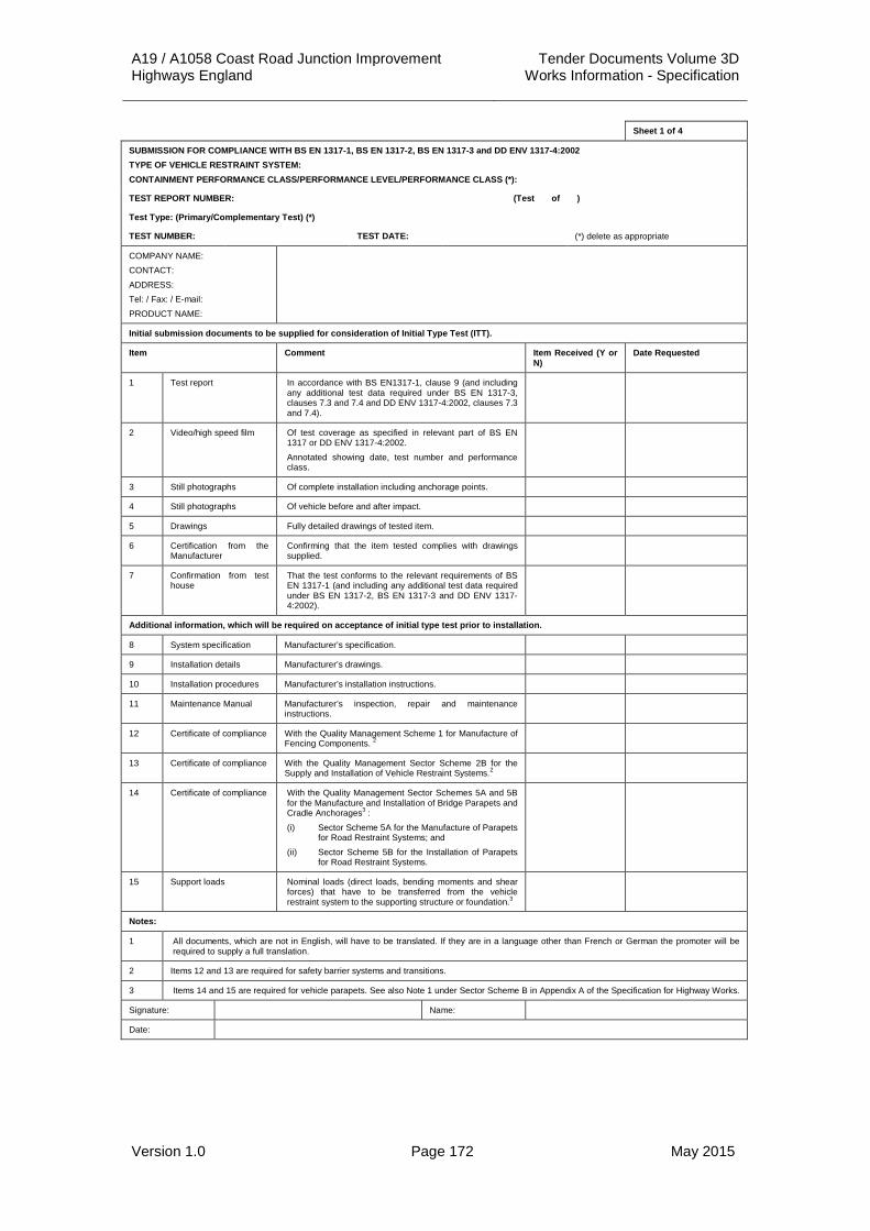
A19 / A1058 Coast Road Junction Improvement Tender Documents Volume 3D Highways England Works Information - Specification
Version 1.0 Page 172 May 2015
Sheet 1 of 4
SUBMISSION FOR COMPLIANCE WITH BS EN 1317-1, BS EN 1317-2, BS EN 1317-3 and DD ENV 1317-4:2002 TYPE OF VEHICLE RESTRAINT SYSTEM: CONTAINMENT PERFORMANCE CLASS/PERFORMANCE LEVEL/PERFORMANCE CLASS (*):
TEST REPORT NUMBER: (Test of )
Test Type: (Primary/Complementary Test) (*)
TEST NUMBER: TEST DATE: (*) delete as appropriate
COMPANY NAME: CONTACT: ADDRESS: Tel: / Fax: / E-mail: PRODUCT NAME:
Initial submission documents to be supplied for consideration of Initial Type Test (ITT).
Item Comment Item Received (Y or N)
Date Requested
1 Test report In accordance with BS EN1317-1, clause 9 (and including any additional test data required under BS EN 1317-3, clauses 7.3 and 7.4 and DD ENV 1317-4:2002, clauses 7.3 and 7.4).
2 Video/high speed film Of test coverage as specified in relevant part of BS EN 1317 or DD ENV 1317-4:2002. Annotated showing date, test number and performance class.
3 Still photographs Of complete installation including anchorage points.
4 Still photographs Of vehicle before and after impact.
5 Drawings Fully detailed drawings of tested item.
6 Certification from the Manufacturer
Confirming that the item tested complies with drawings supplied.
7 Confirmation from test house
That the test conforms to the relevant requirements of BS EN 1317-1 (and including any additional test data required under BS EN 1317-2, BS EN 1317-3 and DD ENV 1317-4:2002).
Additional information, which will be required on acceptance of initial type test prior to installation.
8 System specification Manufacturer’s specification.
9 Installation details Manufacturer’s drawings.
10 Installation procedures Manufacturer’s installation instructions.
11 Maintenance Manual Manufacturer’s inspection, repair and maintenance instructions.
12 Certificate of compliance With the Quality Management Scheme 1 for Manufacture of Fencing Components. 2
13 Certificate of compliance With the Quality Management Sector Scheme 2B for the Supply and Installation of Vehicle Restraint Systems.2
14 Certificate of compliance With the Quality Management Sector Schemes 5A and 5B for the Manufacture and Installation of Bridge Parapets and Cradle Anchorages3 : (i) Sector Scheme 5A for the Manufacture of Parapets
for Road Restraint Systems; and (ii) Sector Scheme 5B for the Installation of Parapets
for Road Restraint Systems.
15 Support loads Nominal loads (direct loads, bending moments and shear forces) that have to be transferred from the vehicle restraint system to the supporting structure or foundation.3
Notes:
1 All documents, which are not in English, will have to be translated. If they are in a language other than French or German the promoter will be required to supply a full translation.
2 Items 12 and 13 are required for safety barrier systems and transitions.
3 Items 14 and 15 are required for vehicle parapets. See also Note 1 under Sector Scheme B in Appendix A of the Specification for Highway Works.
Signature: Name:
Date:
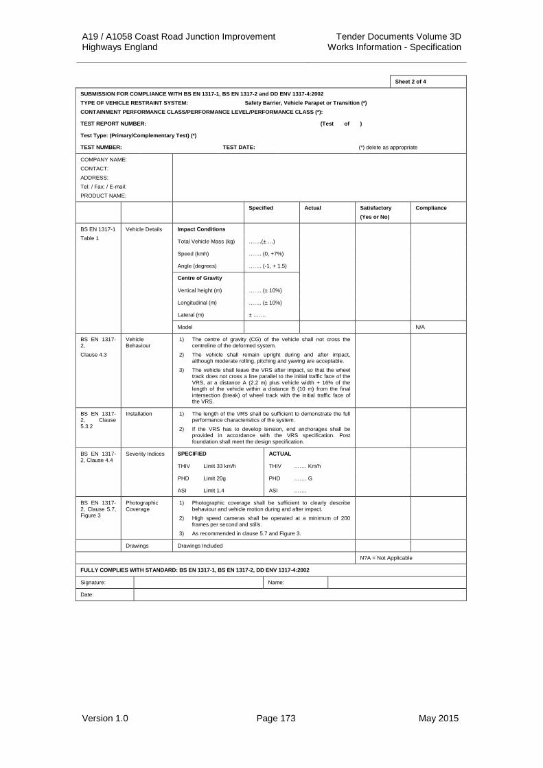
A19 / A1058 Coast Road Junction Improvement Tender Documents Volume 3D Highways England Works Information - Specification
Version 1.0 Page 173 May 2015
Sheet 2 of 4
SUBMISSION FOR COMPLIANCE WITH BS EN 1317-1, BS EN 1317-2 and DD ENV 1317-4:2002 TYPE OF VEHICLE RESTRAINT SYSTEM: Safety Barrier, Vehicle Parapet or Transition (*) CONTAINMENT PERFORMANCE CLASS/PERFORMANCE LEVEL/PERFORMANCE CLASS (*):
TEST REPORT NUMBER: (Test of )
Test Type: (Primary/Complementary Test) (*)
TEST NUMBER: TEST DATE: (*) delete as appropriate
COMPANY NAME: CONTACT: ADDRESS: Tel: / Fax: / E-mail: PRODUCT NAME:
Specified Actual Satisfactory (Yes or No)
Compliance
BS EN 1317-1 Table 1
Vehicle Details Impact Conditions
Total Vehicle Mass (kg) …….(± …)
Speed (kmh) ……. (0, +7%)
Angle (degrees) ……. (-1, + 1.5)
Centre of Gravity
Vertical height (m) ……. (± 10%)
Longitudinal (m) ……. (± 10%)
Lateral (m) ± …….
Model N/A
BS EN 1317-2, Clause 4.3
Vehicle Behaviour
1) The centre of gravity (CG) of the vehicle shall not cross the centreline of the deformed system.
2) The vehicle shall remain upright during and after impact, although moderate rolling, pitching and yawing are acceptable.
3) The vehicle shall leave the VRS after impact, so that the wheel track does not cross a line parallel to the initial traffic face of the VRS, at a distance A (2.2 m) plus vehicle width + 16% of the length of the vehicle within a distance B (10 m) from the final intersection (break) of wheel track with the initial traffic face of the VRS.
BS EN 1317-2, Clause 5.3.2
Installation 1) The length of the VRS shall be sufficient to demonstrate the full performance characteristics of the system.
2) If the VRS has to develop tension, end anchorages shall be provided in accordance with the VRS specification. Post foundation shall meet the design specification.
BS EN 1317-2, Clause 4.4
Severity Indices SPECIFIED ACTUAL
THIV Limit 33 km/h THIV ……. Km/h
PHD Limit 20g PHD ……. G
ASI Limit 1.4 ASI …….
BS EN 1317-2, Clause 5.7, Figure 3
Photographic Coverage
1) Photographic coverage shall be sufficient to clearly describe behaviour and vehicle motion during and after impact.
2) High speed cameras shall be operated at a minimum of 200 frames per second and stills.
3) As recommended in clause 5.7 and Figure 3.
Drawings Drawings Included
N?A = Not Applicable
FULLY COMPLIES WITH STANDARD: BS EN 1317-1, BS EN 1317-2, DD ENV 1317-4:2002
Signature: Name:
Date:

A19 / A1058 Coast Road Junction Improvement Tender Documents Volume 3D Highways England Works Information - Specification
Version 1.0 Page 174 May 2015
Sheet 3 of 4
SUBMISSION FOR COMPLIANCE WITH BS EN 1317-1 and BS EN 1317-3
TYPE OF VEHICLE RESTRAINT SYSTEM: Crash Cushion (Redirective [R] or Non-redirective [NR](*)
TEST REPORT NUMBER: TEST TYPE: (Primary / Complimentary Test) (*)
PERFORMANCE LEVEL: VELOCITY CLASS: (Test of )
TEST NUMBER: TEST DATE: (*) delete as appropriate
COMPANY NAME: CONTACT: ADDRESS: Tel: / Fax: / E-mail: PRODUCT NAME:
Specified Actual Satisfactory (Yes or No)
Compliance
BS EN 1317-1 Vehicle Details Impact Conditions
Total Vehicle Mass (kg) …….(± …)
Speed (kmh) ……. (0, +7%)
Angle (degrees) ……. (-1, + 1.5)
Centre of Gravity
Vertical height (m) ……. (± 10%)
Longitudinal (m) ……. (± 10%)
Lateral (m) ± …….
Model N/A
BS EN 1317-3, Clause 6.2
Crash Cushion Behaviour
1) Elements of the crash cushion shall not penetrate the passenger compartment of the vehicle. Deformations of, or intrusions into, the passenger compartment that could cause serious injuries are not permitted.
2) No major element of the crash cushion, having a solid mass greater than or equal to 2.0kg, shall become totally detached, unless this is required by the working of the crash cushion. No major element of the crash cushion shall impede the path of adjacent traffic. The final position of the detached element shall be considered to determine the displacement classification.
BS EN 1317-3, Clause 6.3
Vehicle Behaviour
1) The vehicle shall remain upright during and after the collision although yawing and moderate rolling and pitching are acceptable. The post-impact trajectory of the test vehicle shall be controlled by means of the exit box shown in Figure 2 and specified as detailed in Tables 11 and 12.
BS EN 1317-3, Clause 7.3.2
Installation 1) The installation of the crash cushion for the test shall comply with the structural design details and the on-road system details as given in the design specification.
BS EN 1317-3, Clause 5.4 and Table 4
Impact Severity Levels
SPECIFIED ACTUAL
Level A: THIV ≤ 44 km/h (Tests 1, 2 & 3)
THIV ≤ 33 km/h (Tests 4 and 5)
ASI ≤ 1.0
Level B: THIV ≤ 44 km/h (Tests 1, 2 & 3)
HIV ≤ 33 km/h (Tests 4 and 5)
ASI ≤ 1.4
Levels A & B: PHD ≤ 20g
BS EN 1317-3, Clause7.7, Figure 4
Photographic Coverage
4) High speed cameras shall be operated at a minimum of 200 frames per second
5) Stills. 6) As recommended in clause 7.7 and Figure 4.
Drawings Drawings Included
N?A = Not Applicable
FULLY COMPLIES WITH STANDARD: BS EN 1317-1 and BS EN 1317-3
Signature: Name:
Date:

A19 / A1058 Coast Road Junction Improvement Tender Documents Volume 3D Highways England Works Information - Specification
Version 1.0 Page 175 May 2015
Sheet 4 of 4
SUBMISSION FOR COMPLIANCE WITH BS EN 1317-1 and DD ENV 1317-4:2002
TYPE OF VEHICLE RESTRAINT SYSTEM: Terminal
PERFORMANCE CLASS: (Test of )
TEST TYPE: (Primary / Complimentary Test) (*)
TEST TYPE NUMBER:
TEST NUMBER: TEST DATE: (*) delete as appropriate
COMPANY NAME: CONTACT: ADDRESS: Tel: / Fax: / E-mail: PRODUCT NAME:
Specified Actual Satisfactory (Yes or No)
Compliance
BS EN 1317-1, Table 1, DD ENV 1314-4:2002, Clauses 7.4 and 7.5
Vehicle Details Impact Conditions
Total Vehicle Mass (kg) …….(± …)
Speed (kmh) ……. (0, +7%)
Angle (degrees) ……. (-1, + 1.5)
Centre of Gravity
Vertical height (m) ……. (± 10%)
Longitudinal (m) ……. (± 10%)
Lateral (m) ± …….
Model N/A
DD ENV 1314-4:2002, Clause 5.4 and 5.5.2
Terminal Behaviour
1) Elements of the terminal shall not penetrate the passenger compartment of the vehicle. Deformations of, or intrusions into, the passenger compartment that could cause serious injuries are not permitted.
2) No major part of the terminal shall become totally detached and come to rest outside the permanent lateral displacement zones defined in clause 5.4.
3) Anchorages and fixings shall perform to the terminal design specifications and other specified requirements as listed in the test report.
DD ENV 1314-4:2002, Clause 5.5.3
Vehicle Behaviour
1) The vehicle shall not overturn, although rolling, yawing and moderate pitching may be accepted. For the Performance Class P1 rolling onto a side may be accepted.
2) The exit box values for the specified test are as defined in Figures 5.6 and 7 (as appropriate).
DD ENV 1314-4:2002, Clause 7.3.2
Installation 1) The terminal shall conform to the structural design details and with the system installation details as given in the design specification of the manufacturer.
DD ENV 1314-4:2002, Clause 5.5.4 Table 5
Impact Severity Levels
SPECIFIED ACTUAL
Level A: THIV ≤ 44 km/h (Tests 1, 2 & 3)
THIV ≤ 33 km/h (Tests 4 and 5)
ASI ≤ 1.0
Level B: THIV ≤ 44 km/h (Tests 1, 2 & 3)
HIV ≤ 33 km/h (Tests 4 and 5)
ASI ≤ 1.4
Levels A & B: PHD ≤ 20g
DD ENV 1314-4:2002, Clause 7.7 and Figure 7
Photographic Coverage
1) Photographic coverage shall be sufficient to describe clearly terminal and vehicle motion during and after impact.
2) High speed cameras shall be operated at a minimum of 200 frames per second
3) Stills.
Drawings Drawings Included
N?A = Not Applicable
FULLY COMPLIES WITH STANDARD: BS EN 1317-1 and DD ENV 1317-4:2002
Signature: Name:
Date:

A19 / A1058 Coast Road Junction Improvement Tender Documents Volume 3D Highways England Works Information - Specification
Version 1.0 Page 176 May 2015
APPENDIX 5/1: DRAINAGE REQUIREMENTS 1. Basis of Hydraulic Design 1.1 The hydraulic design of the system has been carried out using the
Wallingford Procedure and the requirements described in the Design Manual for Roads and Bridges Volume 4 HD 33/96 using the following design:
Software Package Microdrainage WinDes
Ratio R 0.35
M5-60 18 mm
Min Velocity 1.0 m/s
Velocity calculation formula for pipes
Colebrook-White
Velocity calculation formula for ditches
Manning
Pipe Roughness: 0.6 mm (carrier drains) 1.5 mm (filter drains)
Percentage Runoff (PR):
Carriageways, Footways 1.0
Cut Slopes, Field Runoff etc 0.25
Time of Entry
Kerbs and Gullies 4 min
Filter Drains 5 min
Land Drainage 14 min
Minimum Pipe Size:
Surface water 150 mm (generally)
Under road crossings 300 mm
Land Filter Drainage 150 mm
Narrow Filter Drains or Fin Drains As per Highway Construction Details
Cover to pipe To suit pavement construction depth to ensure drainage of pavement formation/sub- formation Typically 1.2 min for mainline Where pavement considerations allow, cover may be reduced in accordance with requirements of HA 40/01
Maximum Chamber Spacing 100 m (nominal) (DEPARTURE 71370, to use 150 m spacing in section of pipeline where depths are over 7m)
Minimum Chamber Size 1200 mm Internal Diameter (except for shallow inspection chambers on Fin / Narrow Filter Drains).

A19 / A1058 Coast Road Junction Improvement Tender Documents Volume 3D Highways England Works Information - Specification
Version 1.0 Page 177 May 2015
Gully Type Channel Entry, Trapped
Gully Spacing HA 102 (where slope 1:300 or above) or LR602 (where slope below 1:300) 70mm/hr design rainfall intensity calculated as per HA 102 + 20% to allow for climate change Type R grating used as basis for design
Maximum Allowable Flow Width Applies to a 1 in 5 year storm return period
Carriageway with full Hardshoulder
1.5 m
Carriageway with Discontinuous Hardshoulder
1.5 m maximum but not encroaching into running lanes
Central reservations 1.5 m maximum but not encroaching into running lanes
Slip Roads and Link Roads with Hardstrip
1 m
Minor Side Roads or Lanes 1 m
Where Footway Immediately Adjacent to Carriageway
0.5m
Elsewhere 0.75m
1.2 The drainage design is shown on Drawings Ref: A19T-DWG-CIV-S00-0500-0002 to 0006 Inclusive.
2. General Requirements for Drains 2.1 Design pipe group numbers which are suffixed ‘s’ shall include sulphate
resistant cement in all concrete. Porous concrete shall not be used in pipe groups so designated.
2.2 All precast and in-situ concrete shall be capable of resisting Class 3 sulphate attack as defined in BRE Special Digest 1:2005.
2.3 All pipes under carriageways less than 1.2 m below the finished road level (measured from finished road level to the soffit of the pipe) shall be encased in concrete in accordance with Clause 503.3 of the Specification for Highways Works to a minimum thickness of 150 mm, except for pipes intended to drain the pavement foundation.
2.4 The ultimate pipe stiffness for thermoplastic pipes shall be 1400 N/m2 when tested in accordance with BS4962 and the resistance to impact shall comply with BS4962 with a striker mass and a 25 mm spherical radius dropped from a height of 1m.
2.5 The creep ratio for PVC-U pipes shall not exceed 2.5 and for PP / PE pipes shall not exceed 4.0 in accordance with BS EN ISO 9967.
2.6 All carrier, foul and filter drains, but excluding all fin and narrow filter drains shall be surveyed by Closed Circuit Television (CCTV) following completion in accordance with Clause 509.5 of the Specification for Highways Works.

A19 / A1058 Coast Road Junction Improvement Tender Documents Volume 3D Highways England Works Information - Specification
Version 1.0 Page 178 May 2015
2.7 All drainage shall be surveyed following completion in accordance with HD 43 of the DMRB as modified by IAN 147 to enable the information to be transferred to the Highways England Drainage Data Management System (previously known as HADDMS).
3. Specific Requirements for Carrier Drains 3.1 Permitted pipe and bedding options for surface water carrier drains are
shown in Table 5/1.1.
3.2 In addition to pipe / bedding combinations listed in HA40 of the DMRB, the following scheme specific combinations apply:
(i) Pipe Group 19 – Flexible/thermoplastic pipe with HCD F1 bed type Z
(ii) Pipe Group 20 – Ductile iron pipe with HCD F1 bed type Z
3.3 All carrier drain pipe joints shall be flexible and watertight in accordance with Clause 504.3 of the Specification for Highways Works.
3.4 The Contractor shall carry out air and / or water tests in accordance with Clause 509 of the Specification for Highways Works on all sections of non-filter drains.
3.5 Backfilling to drains in carriageways shall be with Type 2 sub-base (Clause 803) or normal density concrete C16/20 (Clause 1043). Where Type 2 sub-base is used it shall not contain more than 50% of bituminous planings.
3.6 Backfilling of drains shall be to the underside of the bituminous material, hard paving or topsoil.

A19 / A1058 Coast Road Junction Improvement Tender Documents Volume 3D Highways England Works Information - Specification
Version 1.0 Page 179 May 2015
Table 5/1.1: Permitted Pipe and Bedding Combinations for Carrier Pipes
Pipe Dia (mm)
Pipe Group
Vitrified Clay Precast Concrete GRP Ductile Iron
Stiffness > 6KPa
150 5 ASBFN ASBFN ASBF ASBFN S S S ST ST
225 5 ASBFN ASBFN ASB ASBF S S S ST ST
225 7 ASBF ASBFN ASB ASBF S S S ST ST
300 1 ASBFN ASBFN ASBF ASBF S S S ST ST
300 5 ASBFN ASBFN ASB ASB S S S ST ST
300 7 ASBF ASBFN AS ASB S S S ST ST
300 8 ASBF ASBFN AS ASB S S S ST ST
400 1 ASBF ASBFN ASBFN S S S ST ST
400 2 ASBF ASBFN ASBFN S S S ST ST
400 5 ASB ASBFN ASBFN S S S ST ST
400 6 ASB ASBFN ASBFN S S S ST ST
400 8 ASB ASBF ASBFN S S S ST S
450 5 ASBF ASBFN S S S ST ST
450 6 ASBF ASBFN ASBF S S S ST ST
500 2 ASBF ASBF ASBFN S S S ST ST
500 3 ASBF ASBF ASBFN S S S ST ST
500 5 ASB ASBF ASBFN S S S ST ST
500 6 ASB ASBF ASBFN S S S ST ST

A19 / A1058 Coast Road Junction Improvement Tender Documents Volume 3D Highways England Works Information - Specification
Version 1.0 Page 180 May 2015
Table 5/1.1: Permitted Pipe and Bedding Combinations for Carrier Pipes Continued
Pipe Dia (mm)
Pipe Group
Vitrified Clay Precast Concrete GRP Ductile Iron
Stiffness > 6KPa
600 1 ASB ASBF ASBF ASBFN S S S ST ST
600 5 A ASB ASB ASBF S S S ST ST
600 6 A ASB ASB ASB S S S ST ST
600 7 A ASB ASB ASB S S S ST ST
600 9 AS AS ASB S S S S S
600 10 AS AS ASB S S S S S
750 1 ASB ASBF ASBFN S S S ST ST
750 2 ASB ASBF ASBF S S S ST ST
750 5 A ASB ASBF S S S ST ST
750 6 A ASB ASB S S S ST ST
750 7 AS ASB S S S ST ST
900 5 A ASB ASBF S S S ST ST
900 6 A ASB ASBF S S S ST S
900 7 ASB ASBF S S S ST S
900 8 ASB ASB S S S S S
900 9 AS ASB S S S S S
900 11 AS ASB S S S S S
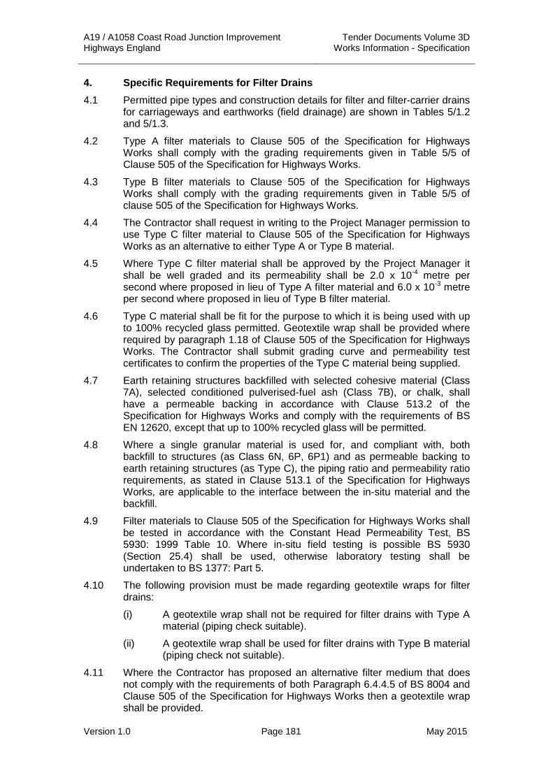
A19 / A1058 Coast Road Junction Improvement Tender Documents Volume 3D Highways England Works Information - Specification
Version 1.0 Page 181 May 2015
4. Specific Requirements for Filter Drains 4.1 Permitted pipe types and construction details for filter and filter-carrier drains
for carriageways and earthworks (field drainage) are shown in Tables 5/1.2 and 5/1.3.
4.2 Type A filter materials to Clause 505 of the Specification for Highways Works shall comply with the grading requirements given in Table 5/5 of Clause 505 of the Specification for Highways Works.
4.3 Type B filter materials to Clause 505 of the Specification for Highways Works shall comply with the grading requirements given in Table 5/5 of clause 505 of the Specification for Highways Works.
4.4 The Contractor shall request in writing to the Project Manager permission to use Type C filter material to Clause 505 of the Specification for Highways Works as an alternative to either Type A or Type B material.
4.5 Where Type C filter material shall be approved by the Project Manager it shall be well graded and its permeability shall be 2.0 x 10⁻⁴ metre per second where proposed in lieu of Type A filter material and 6.0 x 10⁻³ metre per second where proposed in lieu of Type B filter material.
4.6 Type C material shall be fit for the purpose to which it is being used with up to 100% recycled glass permitted. Geotextile wrap shall be provided where required by paragraph 1.18 of Clause 505 of the Specification for Highways Works. The Contractor shall submit grading curve and permeability test certificates to confirm the properties of the Type C material being supplied.
4.7 Earth retaining structures backfilled with selected cohesive material (Class 7A), selected conditioned pulverised-fuel ash (Class 7B), or chalk, shall have a permeable backing in accordance with Clause 513.2 of the Specification for Highways Works and comply with the requirements of BS EN 12620, except that up to 100% recycled glass will be permitted.
4.8 Where a single granular material is used for, and compliant with, both backfill to structures (as Class 6N, 6P, 6P1) and as permeable backing to earth retaining structures (as Type C), the piping ratio and permeability ratio requirements, as stated in Clause 513.1 of the Specification for Highways Works, are applicable to the interface between the in-situ material and the backfill.
4.9 Filter materials to Clause 505 of the Specification for Highways Works shall be tested in accordance with the Constant Head Permeability Test, BS 5930: 1999 Table 10. Where in-situ field testing is possible BS 5930 (Section 25.4) shall be used, otherwise laboratory testing shall be undertaken to BS 1377: Part 5.
4.10 The following provision must be made regarding geotextile wraps for filter drains:
(i) A geotextile wrap shall not be required for filter drains with Type A material (piping check suitable).
(ii) A geotextile wrap shall be used for filter drains with Type B material (piping check not suitable).
4.11 Where the Contractor has proposed an alternative filter medium that does not comply with the requirements of both Paragraph 6.4.4.5 of BS 8004 and Clause 505 of the Specification for Highways Works then a geotextile wrap shall be provided.

A19 / A1058 Coast Road Junction Improvement Tender Documents Volume 3D Highways England Works Information - Specification
Version 1.0 Page 182 May 2015
4.12 Geotextile fabric membranes in filter drains, when tested in accordance with Clause 609.4 of the Specification for Highways Works, shall:
(i) Sustain a tensile load of not less than 0.7 kN per metre run.
(ii) Allow a water flow through it at a rate of 50 - 100 l/m²/s.
(iii) Have a maximum breakthrough head of 5 mm.
(iv) Have a size distribution of pore openings such that 0.10 mm < Mean O90 < 0.35 mm.
(v) Have a pore size 0 - 90 less that the particle size D85 of the adjacent sub-soil or fill material.
(vi) Have a weight not less than 125g/m², Terram 1000 or similar approved.
4.13 Jointing of geotextiles shall be by overlapping only and all laps shall be 300 mm minimum.
4.14 Any punctures or damage to geotextiles shall be made good by overlaying with geotextile having an overlap of 300 mm from the edge of the damaged area.
4.15 Where Type B or C filter media or no fines concrete shall be specified in filter drains, with either topsoil or paving top, a geotextile shall be required above the filter media or no fines concrete to prevent ingress / loss of fines.
4.16 Perforated concrete pipes to BS 5911 Part 110 shall comply with the strength requirements of Table 2 of BS 5911.
4.17 Perforations in concrete pipes to BS 5911 Part 110 shall have an area of not less than 1000 mm2 of holes per metre length of pipe.
4.18 Filter drains in verges shall be constructed using perforated or slotted pipes. Where perforations are provided only to part of the circumference of the pipe, the perforations shall be laid uppermost. Joints in filter drains shall be as per Clause 504.6 of the Specification for Highways Works.
4.19 Coilable perforated pipes to Clause 503.2 of the Specification for Highways Works may only be used for land drainage applications and narrow filter drains. They shall not be used for any other highway drainage application.
4.20 Flexible twin walled pipes may be used to connect into chambers where required. Lengths of pipe shall not exceed 6m prior to a chamber connection.

A19 / A1058 Coast Road Junction Improvement Tender Documents Volume 3D Highways England Works Information - Specification
Version 1.0 Page 183 May 2015
Table 5/1.2: Allowable Pipe Types for Filter Drains
Pipe Dia (mm)
Pipe Group
Vitrified Clay Precast Concrete Thermoplastic
L 95 120 160 200 L M H Structured SRD 41
150 1 - - - Y Y - - - Y -
150 2 - - - Y Y - - - Y -
150 3 - - - Y Y - - - Y -
225 1 - - - Y Y Y Y - Y -
225 2 - - - Y Y Y Y - Y -
225 3 - - - Y Y Y Y - Y -
225 5 - - - Y Y Y Y - Y -
225 8 - - - Y Y Y Y - Y -
300 1 - - - Y Y Y Y - Y Y
300 3 - - - Y Y Y Y - Y Y
300 5 - - - Y Y - Y - Y Y
300 6 - - - Y Y - Y - Y Y
450 1 - - Y Y Y - Y Y Y -
450 3 - - Y Y Y - Y Y Y -
500 2 - Y Y Y Y - Y Y Y -
Y = Permitted pipe type

A19 / A1058 Coast Road Junction Improvement Tender Documents Volume 3D Highways England Works Information - Specification
Version 1.0 Page 184 May 2015
Table 5/1.3: Allowable Filter Drains Details
Location
Central reserve and Verges
Outside Carriageway (e.g. toe of embankment)
Drain Type (Surface level) Filter media to ground level
Drain Type (Lower Trench) Refer to HCD Drawing F2
G, H, I
5. Chambers and Gullies 5.1 Chambers shall be constructed in accordance with the following:
(i) The project drainage standard details.
(ii) Highway Construction Details (HCDs) (F Series) contained in Volume 3 of the Manual of Contract Documents for Highway Works (MCHW).
5.2 The project specific standard details shall take precedence should there be any conflict of detail. The following are chamber types that have or may be selected:
Table 5/1.4: Chambers and Gully Types
Chamber Ref. Chamber Type
Depth Construction Drawing No.
1A to 1C Benched Manhole
1.5 + pipe dia Brick or in-situ concrete
HCD F3
2A to 2B Benched Manhole
1m to 1.5m + pipe dia
Precast Concrete
HCD F4
3A to 3D Benched Manhole
1.5m to 3m + pipe dia
Precast Concrete
HCD F5
4A to 4C Benched Manhole
3m to 6m + pipe dia
Precast Concrete
HCD F6
7A to 7D Catchpit 0 to 3m (to pipe soffit)
0 to 3m (to pipe soffit)
Precast concrete
HCD F11
8 Catchpit Unspecified Clayware, PC or PVC-U
HCD F12
S1 Modified Deep catchpit
6m to 12m + pipe dia
Precast concrete
TBC
S1a Penstock Chamber
Unspecified Precast concrete
TBC

A19 / A1058 Coast Road Junction Improvement Tender Documents Volume 3D Highways England Works Information - Specification
Version 1.0 Page 185 May 2015
Table 5/1.4: Chambers and Gully Types Continued
Chamber Ref. Chamber Type
Depth Construction Drawing No.
G Gully 1 to 1.5m approx.
PC or in-situ concrete
TBC
GS Sumpless gully
1m approx. Various (see HCD)
TBC
Chamber Cover on side slopes
TBC
Pollution Control Interceptor
TBC
Flow Control Chamber
Catchpit 3 - 6m Precast concrete
TBC
5.3 The Contractor shall ensure that in manholes pipe entry and outfall soffit levels shall be kept equal unless shown otherwise on the drainage layout drawings.
5.4 The Contractor shall ensure that weep pipes shall be set with their inverts level to that of the adjacent pipe. The outgoing invert level shall be set below all incoming invert levels to allow water from the weep pipes, if present, to flow out of a Type 7 chamber.
5.5 Gullies shall be constructed in accordance with the Highway Construction Details Drawing No F13 and shall be trapped.
5.6 Saddles shall only be permitted where new gully connections are required on an existing pipe network.
5.7 Chamber and gully gratings, covers and frames shall be in ductile iron in accordance with BS EN 124 and installed in accordance with HA104 of the DMRB. The type of cover shall be in accordance with Table 5/1.5:
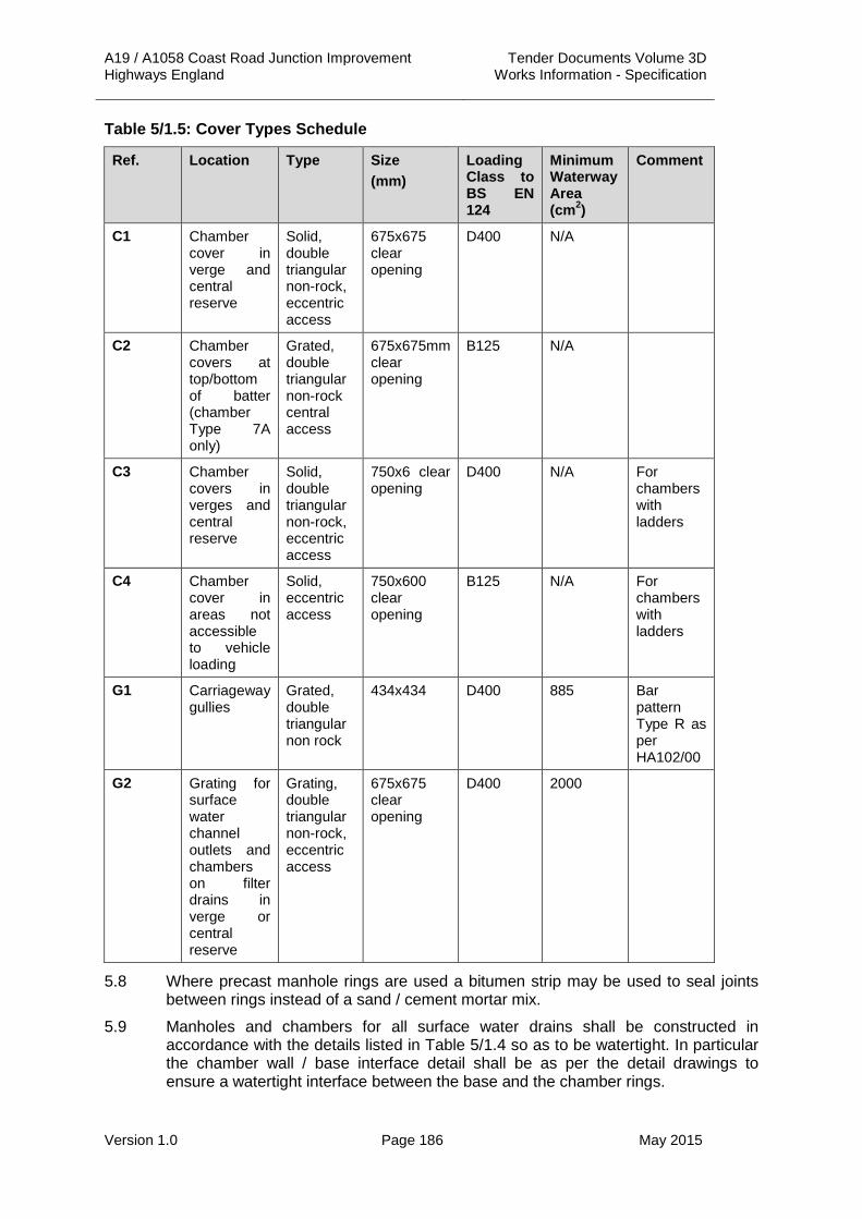
A19 / A1058 Coast Road Junction Improvement Tender Documents Volume 3D Highways England Works Information - Specification
Version 1.0 Page 186 May 2015
Table 5/1.5: Cover Types Schedule
Ref. Location Type Size (mm)
Loading Class to BS EN 124
Minimum Waterway Area (cm2)
Comment
C1 Chamber cover in verge and central reserve
Solid, double triangular non-rock, eccentric access
675x675 clear opening
D400 N/A
C2 Chamber covers at top/bottom of batter (chamber Type 7A only)
Grated, double triangular non-rock central access
675x675mm clear opening
B125 N/A
C3 Chamber covers in verges and central reserve
Solid, double triangular non-rock, eccentric access
750x6 clear opening
D400 N/A For chambers with ladders
C4 Chamber cover in areas not accessible to vehicle loading
Solid, eccentric access
750x600 clear opening
B125 N/A For chambers with ladders
G1 Carriageway gullies
Grated, double triangular non rock
434x434 D400 885 Bar pattern Type R as per HA102/00
G2 Grating for surface water channel outlets and chambers on filter drains in verge or central reserve
Grating, double triangular non-rock, eccentric access
675x675 clear opening
D400 2000
5.8 Where precast manhole rings are used a bitumen strip may be used to seal joints between rings instead of a sand / cement mortar mix.
5.9 Manholes and chambers for all surface water drains shall be constructed in accordance with the details listed in Table 5/1.4 so as to be watertight. In particular the chamber wall / base interface detail shall be as per the detail drawings to ensure a watertight interface between the base and the chamber rings.

A19 / A1058 Coast Road Junction Improvement Tender Documents Volume 3D Highways England Works Information - Specification
Version 1.0 Page 187 May 2015
6. Headwalls 6.1 There are no drainage headwalls required in this Contract at the date of Tender.
7. Separators 7.1 Separators shall be installed where indicated on the layout drawings. Oil / water
separators shall be Class 1 bypass separators with integral silt storage capacity, sized in accordance with the Environment Agency Pollution Prevention Guidelines PPG3 “Use and Design of Oil Separators in Surface Water Drainage”. Separator sizes shall be as specified in terms of nominal size (NSB) and detailed on the layout drawings and chamber schedules.
7.2 Separator tanks shall comply with BS EN 858-1. A list of compliant separators is available from the Environment Agency.
7.3 In accordance with Pollution Prevention Guidelines (PPG3) separators shall provide a facility for a high oil level alarm. The high oil level alarm shall be indicated by a flashing beacon powered by solar panels or other suitable power supply.
7.4 Separators shall be installed in accordance with the Manufacturer’s Recommendations
7.5 Spillage containment devices shall be provided at outfalls where indicated on the layout drawings. Devices shall provide a minimum storage volume of 20m3. The volume shall be provided by means of an enlarged pipe (typically 900mm diameter pipe) with a penstock catchpit at the downstream end.
8. Valves 8.1 Where flap valves shall be installed on headwalls this shall be shown on the
drainage layout drawings.
8.2 Requirements for flap valves are given on the relevant standard detail drawings as well as below. Flap valves may be high density polyethylene (HDPE), cast iron or other material suitable for purpose. Flap valves shall be capable of withstanding 5 m head of water (for a short period). Flap valves shall be installed in accordance with the manufacturer’s instructions.
8.3 Flap valves shall be single link type for 150mm diameter or less and double link for all sizes over 150mm diameter.
8.4 All flap valves over 225mm diameter shall be provided with lifting points.
8.5 Where penstocks are required to be fitted either on headwalls or in chambers this shall be as shown on the drainage layout drawings.
8.6 Manual penstocks in a chamber shall be installed in accordance with the manufacturer’s recommendations.

A19 / A1058 Coast Road Junction Improvement Tender Documents Volume 3D Highways England Works Information - Specification
Version 1.0 Page 188 May 2015
8.7 Penstocks shall have a standard hydrant compatible key fitting with non-rising stem and shall be installed in accordance with the manufacturer’s instructions. Penstocks, unless otherwise stated, shall only cater for on-seating pressure of 5 m head. Penstocks may be constructed of HDPE, cast iron or other material suitable for purpose.
9. Existing Drainage 9.1 The Contractor shall maintain all existing drainage within the Site Boundary until the
new permanent drainage is installed and functioning satisfactorily or alternatively provide temporary drainage systems as required so that the drainage of the carriageway is not impaired.
9.2 Connections to and from existing drainage and existing drainage that shall be retained shall be as shown on the drainage layout drawings.
9.3 All existing pipework, except filter drains, within 1 m of the carriageway formation level which shall become redundant shall either be excavated and removed from the Works or grouted up.
9.4 Existing filter drains shall be excavated and removed from the Site and backfilled with acceptable material.
9.5 Existing drainage incorporated within the Works shall be cleansed in accordance with Clause 520 of the Specification for Highways Works and cleared of debris and subject to a CCTV survey. Repairs shall be carried out as required to ensure drains fulfil the drainage design requirements. These drains shall then be flushed in accordance with Clause 509.5 of the Specification for Highways Works.
9.6 Pipe connections shall be made in accordance with Clause 506 of the Specification for Highways Works.
9.7 Before connecting new drains into existing drainage runs trial pits shall be dug to ascertain the exact level of the existing pipe. If the existing pipe is higher or substantially lower that the new drain, the Project Manager’s guidance shall be sought.
10. Balancing Ponds and Outfalls 10.1 Locations of outfalls are shown on the drainage layout drawings.
11. Proposed Soakaways 11.1 There are no soakaways required in this Contract at the date of Tender.
12. Specific Requirements for Existing Borehole Soakaways 12.1 There are no existing borehole soakaways included in this Contract at the date of
Tender.
13. Ditches, Cut-Off Drainage and Watercourses 13.1 The realignment of existing ditches and watercourses are shown on the drainage
layout drawings.
13.2 Existing cut-off ditches that shall be retained where the slope / retaining wall solutions allow this shall be cleared from debris and vegetation causing significant impediment to flows.
13.3 Where insufficient space is available for either retention of an existing ditch or a realigned new one, a cut-off filter drain shall be used. Details of filter drain for this purpose shall be as per drawing F2 of HCD.
13.4 Class 6C material may be used as “rip-rap” material.

A19 / A1058 Coast Road Junction Improvement Tender Documents Volume 3D Highways England Works Information - Specification
Version 1.0 Page 189 May 2015
14. Land Drains 14.1 Where land drains are encountered in the construction of the Works, the Project
Manager shall be consulted for an appropriate solution.
14.2 The position of each existing land drain when intercepted shall be recorded, and this information shall be included in the As-built records.
15. Sub-Surface Drainage to Structures 15.1 Subsurface drainage to structures shall be constructed as shown on the structures
drawings. The connections from the structures drainage shall be as shown on the drainage layout drawings.
15.2 Where bridge deck drainage shall be required it shall be constructed as shown on the structures drawings. The connections from such drainage units shall be as shown on the drainage layout drawings.
15.3 Bridge deck drainage units used shall allow for drainage of the pavement layers.
16. Drainage Setting Out 16.1 Typical offsets for pre-earthworks / land drainage features are given on the
earthworks drainage standard detail drawings. Where offsets vary from the norm the offsets are shown on the drainage layout drawings and Chamber Schedules of this Specification.
17. Tunnelling and Shaft Sinking Works 17.1 Any drainage tunnelling Works incorporating microtunnelling and pipe jacking shall
be carried out in accordance with Section 11 of the Civil Engineering Specification for the Water Industry (CESWI) 7th Edition.

A19 / A1058 Coast Road Junction Improvement Tender Documents Volume 3D Highways England Works Information - Specification
Version 1.0 Page 190 May 2015
APPENDIX 5/1: ANNEX A1 PIPE SCHEDULES Please note schedules shown are provisional and subject to change.
Table 5/1.A1: Pipe Schedules

A19 / A1058 Coast Road Junction Improvement Tender Documents Volume 3D Highways England Works Information - Specification
Version 1.0 Page 191 May 2015
APPENDIX 5/1: ANNEX A1 PIPE SCHEDULES CONTINUED Table 5/1.A1: Pipe Schedules Continued

A19 / A1058 Coast Road Junction Improvement Tender Documents Volume 3D Highways England Works Information - Specification
Version 1.0 Page 192 May 2015
APPENDIX 5/1: ANNEX A1 PIPE SCHEDULES CONTINUED Table 5/1.A1: Pipe Schedules Continued

A19 / A1058 Coast Road Junction Improvement Tender Documents Volume 3D Highways England Works Information - Specification
Version 1.0 Page 193 May 2015
APPENDIX 5/1: ANNEX A1 PIPE SCHEDULES CONTINUED Table 5/1.A1: Pipe Schedules Continued

A19 / A1058 Coast Road Junction Improvement Tender Documents Volume 3D Highways England Works Information - Specification
Version 1.0 Page 194 May 2015
APPENDIX 5/1: ANNEX A1 PIPE SCHEDULES CONTINUED Table 5/1.A1: Pipe Schedules Continued

A19 / A1058 Coast Road Junction Improvement Tender Documents Volume 3D Highways England Works Information - Specification
Version 1.0 Page 195 May 2015
APPENDIX 5/1: ANNEX A1 PIPE SCHEDULES CONTINUED Table 5/1.A1: Pipe Schedules Continued

A19 / A1058 Coast Road Junction Improvement Tender Documents Volume 3D Highways England Works Information - Specification
Version 1.0 Page 196 May 2015
APPENDIX 5/1: ANNEX A1 PIPE SCHEDULES CONTINUED Table 5/1.A1: Pipe Schedules Continued

A19 / A1058 Coast Road Junction Improvement Tender Documents Volume 3D Highways England Works Information - Specification
Version 1.0 Page 197 May 2015
APPENDIX 5/1: ANNEX B1 CHAMBER SCHEDULES 1. The chamber schedules are shown on Drawing No. A19T-DWG-CIV-S00-0500-
0006.

A19 / A1058 Coast Road Junction Improvement Tender Documents Volume 3D Highways England Works Information - Specification
Version 1.0 Page 198 May 2015
APPENDIX 5/1: ANNEX G1 SEPARATOR SCHEDULES Table 5/1.G1: Separator Schedule

A19 / A1058 Coast Road Junction Improvement Tender Documents Volume 3D Highways England Works Information - Specification
Version 1.0 Page 199 May 2015
APPENDIX 5/1: ANNEX H1 FLOW CONTROL SCHEDULES Table 5/1.H1: Flow Control Schedule
ONLINE CONTROLS
SW57 (6.008) Non Return Valve
SW60 (1.052) Orifice Plate 0.50m dia
SW61 (1.053) Orifice Plate 0.54m dia
SW62 (1.054) Orifice Plate 0.55m dia
SW63 (1.055) Orifice Plate 0.57m dia
SW64 (1.056) Orifice Plate 0.58m dia
SW97 (10.044) Orifice Plate 1.20m dia
SW98 (10.045) Orifice Plate 1.10m dia
SW99 (10.046) Orifice Plate 1.10m dia
SW100 (10.047) Orifice Plate 1.10m dia
SW101 (10.048) Orifice Plate 1.10m dia
SW102 (10.049) Orifice Plate 1.10m dia
SW103 (10.050) Orifice Plate 1.10m dia
SW104 (10.051) Orifice Plate 1.30m dia

A19 / A1058 Coast Road Junction Improvement Tender Documents Volume 3D Highways England Works Information - Specification
Version 1.0 Page 200 May 2015
APPENDIX 5/2: SERVICE DUCT REQUIREMENTS 1. Traffic Signal Ducts 1.1 Traffic signals ducts shall be provided in the locations shown on the traffic signal
layout drawing (Ref: A19T-DWG-CIV-S00-1200-0006).
1.2 The Contractor shall prove the integrity of the existing traffic signal duct system to establish its presence and assess if it can be reused. The Contractor shall propose any such reuse for acceptance by the Project Manager.
1.3 Traffic signal cabling shall not share ducts with any other cabling unless specifically agreed by the Project Manager.
1.4 The Contractor shall install any such new ducts in accordance with drawing MCX 814 sheets 1 to 4 of Volume 3 of the Specification for Highways Works.
1.5 The Contractor shall agree with the Project Manager the depth of any such carriageway duct crossings taking cognisance of the depths of the existing utility services apparatus in the carriageway.
1.6 Ducts for traffic signals shall meet the requirements of BS EN 50086 Parts 2 to 4 inclusive and shall be sufficiently rigid to experience no deformation during backfill and compaction but shall be capable of bending to the radius required.
1.7 Ducts shall have a minimum internal diameter 100mm. All ducts shall be manufactured from Medium or High Density Polyethylene, with a minimum wall thickness of 5mm.
1.8 All road crossings shall have four 100mm ducts unless otherwise stated.
1.9 Ducts shall be smooth-bore and supplied in 6 metre lengths complete with couplings.
1.10 The ducts for traffic signals shall be coloured orange throughout their length and shall be indelibly marked, by indentation, with the legend “Traffic Signals” as appropriate in 9 mm high white characters at intervals of 1 m. When laid the wording shall be visible from above.
1.11 The system of ducting and service duct chambers for traffic signals shall be for the sole use of traffic signals equipment.
1.12 The Contractor shall supply samples of all proposed ducts to the Project Manager for approval prior to use.
1.13 Prior to completion of the works, the ducts shall be tested in accordance with Clause. 509.9 of the Specification for Highways Works.
1.14 Where ducts are not connecting to chambers, marker blocks as shown on drawing I1 of Volume 3 of the Specification for Highways Works shall be used.
2. Requirements for Duct Chambers 2.1 Traffic signal chambers shall be constructed using interlocking duct entry sections
and raising pieces. Each section shall comprise of a twin wall construction that shall be injection moulded from comer polypropylene.
2.2 Traffic signal chambers shall be capable of supporting a vertical load of 25 tonnes unsupported and 40 tonnes with 150 mm thick concrete surround.
2.3 A range of interlocking sections shall be available for chamber construction such that holes in the duct entry sections shall allow for both 50 mm and 100 mm diameter ducts.

A19 / A1058 Coast Road Junction Improvement Tender Documents Volume 3D Highways England Works Information - Specification
Version 1.0 Page 201 May 2015
2.4 Traffic signals chambers shall be installed on a flat bed of ST4 concrete with a 100 mm diameter drainage hole and adequate drain away as per note 4 of drawing MCX 0815 Sheet 3 of Volume 3 of the Specification for Highways Works.
2.5 All traffic signal chambers shall be installed a minimum of 2 m away from all adjacent carriageways.
2.6 The traffic signal chamber cover and frame shall be to Class D400 unless otherwise agreed with the Project Manager.
2.7 All traffic signal chamber covers shall be provided with a multi-directional anti-slip surface, with an average skid resistance value of 84 (dry) and 50 (wet), manufactured from a high strength reinforced composite cover in accordance with BS EN124 “Gully tops and manhole tops for vehicles and pedestrian areas” with a load classification of D400.
2.8 All traffic signal covers shall be coloured black and shall be individually badged to identify the service in the chamber beneath i.e. “Traffic Signals”.
2.9 Frames shall be of galvanised steel construction and compatible with both the cover and chamber to maintain the specified clear opening.
2.10 Where traffic signal chamber covers are in tactile paving the Contractor shall use recessed covers to allow the tactile surface to be installed within the cover using an appropriate mortar bed.
2.11 Ducts shall be installed in each traffic signal chamber such that they extend a distance of 25 mm +/- 2 mm into the chamber.
2.12 All chambers shall be installed as per the manufacturer’s instructions.
2.13 Traffic signal chambers at the termination of cross carriageway ducts shall be a minimum of 1050 mm deep and shall be 850mm deep at all other locations.

A19 / A1058 Coast Road Junction Improvement Tender Documents Volume 3D Highways England Works Information - Specification
Version 1.0 Page 202 May 2015
APPENDIX 5/4: FIN DRAINS AND NARROW FILTER DRAINS 1. Permitted Alternative Types of Fin Drain and Narrow Filter Drain 1.1 The type of fin drain and narrow filter drain shall be chosen by the Contractor and
shall comply with HCD drawings F18, F19 and F20.
2. Location and Types of Drains 2.1 Location of fin drain and narrow filter drain are shown on the Drainage Layout
drawings A19T-DWG-CIV-S00-0500-0021-0024 inclusive.
2.2 A Schedule of filter drains is included in Annex C1 Narrow Filter Drain Schedules of this Specification.
3. Geotextile Details 3.1 The geotextile shall allow water through it at right angles to its principle planes in
either direction at a rate of not less than 50 litres/m2sec under a constant head of water of 100 mm, determined in accordance with Clause 514.4(v) of the Specification for Highways Works.
3.2 Geotextile membranes used in Narrow Filter Drains shall have a 90% pore size (090) not greater than 100 microns for use in cohesive soils and between 100 and 300 microns in granular soils as defined in Clauses 514.4(iv) and 515.3 of the Specification for Highways Works.
4. Fin Drains 4.1 The long term in plane flow of the fin drains shall be 0.2 l/m/sec.
5. Pipe Details 5.1 The minimum pipe diameter shall be 100mm unless shown otherwise on the
drainage layout drawings A19T-DWG-CIV-S00-0500-002 – 0006 inclusive.
6. Trench Backfill Material for Fin Drain 6.1 Trench backfill material for fin drains shall be original as-dug material.
7. Granular Material in Type 8 NFD 7.1 Granular material in Type 8 narrow filter drain shall be in accordance with Clause
515 of the Specification for Highways Works.
7.2 Permeability of granular material in Type 8 narrow filter drain shall be less than 1 x 10⁻⁴ m/s.
7.3 D15 particle size for granular material shall be less than 0.1 mm.
8. Maximum Drain Slope Angle 8.1 The maximum drain slope angle shall be 15% not including the section of pipe
leading to the rodding eye.
9. Dimensions of Fin Drains and Narrow Filter Drains 9.1 Fin drains and narrow filter drains shall have the dimensions shown on the HCD
drawings.
10. Required Installation Levels 10.1 For pavement locations where capping is provided the minimum required depths
relative to the pavement construction shall be as indicated on the HCD drawings
A19 / A1058 Coast Road Junction Improvement Tender Documents Volume 3D Highways England Works Information - Specification
Version 1.0 Page 203 May 2015
10.2 For pavement locations where capping is omitted and a sub-base only option is provided, the soffit of the fin or narrow filter drain shall be a minimum of 50 mm below formation level.
10.3 Where the depth of the narrow filter drain shall be increased in order to intercept rising groundwater levels the extents shall be as shown on the drainage layout drawings and in the narrow filter drain schedules. These documents will also indicate the depths required.
10.4 Notwithstanding the above, fin or narrow filter drains shall always be provided with a positive fall towards their outfall.
11. Certification 11.1 A current Highways England Product Approval Scheme (HAPAS) or British Board of
Agrément (BBA) Certificate for the fin drains to be used in the Works shall be provided before any materials are used. If there are no fin drains available which have a current BBA Certificate, evidence that the fin drains have the specified properties listed above and in Clause 514.4 of the Specification for Highways Works shall be provided before installation.
11.2 All geotextile fin drains delivered to Site shall be marked in accordance with BS EN 30320 ‘Geotextiles - Identification on Site’.

A19 / A1058 Coast Road Junction Improvement Tender Documents Volume 3D Highways England Works Information - Specification
Version 1.0 Page 204 May 2015
APPENDIX 5/5: COMBINED DRAINAGE AND KERB SYSTEMS 1. General 1.1 Combined drainage and kerb units shall comply with the requirements of BS EN
1433 and have certification in accordance with IAN 117.
2. Location and Types of Combined Drainage and Kerb Systems 2.1 Location and type of combined drainage and kerb drain are shown on the Drainage
Layout drawings A19T-DWG-CIV-S00-0500-0002 – 0006 inclusive.
2.2 Combined drainage and kerb systems shall comprise of prefabricated units produced by an approved manufacturer. All combined drainage and kerb systems shall be constructed to the manufacturer’s standards.
2.3 Joints shall be sealed along their whole perimeter with a sealant as recommended by the manufacturer.
2.4 The units shall be laid in accordance with Clause 1101.5 of the Specification for Highways Works.
3. Limiting Dimensions 3.1 The overall dimensions and details of the standard combined drainage and kerb
systems are shown on the Combined Drainage and Kerb Block Schedule of this specification.
3.2 Combined drainage and kerb systems units shall have either half battered or full battered (splay) profile and kerb show as indicated on the Footway, Kerbs and Paved Areas Layout Drawings (Ref: A19T-DWG-CIV-S00-1100-0001 to 0004 inclusive).
3.3 Components shall have a base unit depth as stated in Annex D1 of this Appendix 5/1. Shallow units shall be indicated by the suffix (S) and deep units shall be indicated by the suffix (D) on the drainage layout drawings.
4. Strength Requirements 4.1 The combined drainage and kerb units shall be Class D and be capable of bearing
a minimum wheel load of 400kN in accordance with BS EN 124: 1994.
5. Special fittings 5.1 Any covers on the combined drainage and kerb systems outlets or access
chambers shall be to a load Class D400 of BS EN 124: 1994.
5.2 Access chambers and outlets shall comprise of prefabricated units produced by the combined drainage and kerb manufacturer. All chambers shall be constructed to the manufacturer’s standards.
6. Hydraulic Design Parameters 6.1 The Contractor shall carry out the design in accordance with the requirements of
the Specification of Highway Works, this Appendix and the manufacturer's guidance and instructions.
6.2 The design flows shall be calculated using:
(i) a rainfall intensity of 83mm/hr
(ii) a catchment area based on the length of combined drainage and kerb system and the average width of paved area.

A19 / A1058 Coast Road Junction Improvement Tender Documents Volume 3D Highways England Works Information - Specification
Version 1.0 Page 205 May 2015
6.3 The capacity of the combined drainage and kerb system shall not exceed 85% when using the calculated design flows.
6.4 The proposals for combined drainage and kerb systems shall be referred to the Designer who shall undertake any necessary design checks to ensure co-ordination with other parts of the drainage design. The following information shall be submitted at least two weeks before construction of the combined drainage and kerb systems:
(i) calculated design flows and maximum capacities at the outfalls
(ii) typical details of the channel units including size and material
(iii) construction details including a cross sectional detail
(iv) outfall details including construction details and proposed locations of each outfall to the piped drainage system.
7. Bridge Deck Drainage 7.1 Bridge deck drainage units shall be as shown in Annex D1 Combined Drainage and
Kerb Block Schedule of this specification Appendix 5/1 and incorporate sub-surface drainage slots. The design has been based on Envirodeck unit system.
7.2 Bridge deck drainage units shall allow for rodding/cleansing.
7.3 Bridge deck drainage units shall be to Class D capable of bearing a minimum wheel load of 400kN in accordance with BS EN 124:1994.
7.4 The location of bridge deck drainage units are shown on the drainage layout drawings and the corresponding structures drawing.
7.5 The traffic face of bridge deck drainage units shall be splayed at 45 degrees.

A19 / A1058 Coast Road Junction Improvement Tender Documents Volume 3D Highways England Works Information - Specification
Version 1.0 Page 206 May 2015
APPENDIX 5/6: LINEAR DRAINAGE CHANNEL SYSTEMS 1. Location and types of Linear Drainage Channel Systems 1.1 The location and type of linear drainage channel systems are shown on the
Drainage Layout drawings A19T-DWG-CIV-S00-0500-0002 – 0006 inclusive.
2. Hydraulic Design Parameters 2.1 The Contractor shall carry out the design in accordance with the requirements of
the Specification of Highway Works, this Appendix and the manufacturer's guidance and instructions.
2.2 The design flows shall be calculated using:
(i) a rainfall intensity of 83mm/hr
(ii) a catchment area based on the length of linear drainage channel system and the average width of paved area.
2.3 The capacity of the linear drainage channel system shall not exceed 85% when using the calculated design flows.
2.4 The proposals for linear drainage channel systems shall be referred to the Designer who shall undertake any necessary design checks to ensure co-ordination with other parts of the drainage design. The following information shall be submitted at least two weeks before construction of the linear drainage channel systems:
(i) calculated design flows and maximum capacities at the outfalls
(ii) typical details of the channel units including size and material
(iii) construction details including a cross sectional detail
(iv) outfall details including construction details and proposed locations of each outfall to the piped drainage system.
3. Strength requirements 3.1 The linear drainage channel system shall be capable of receiving Class D400
loading as per BS EN 1433. The Contractor shall provide evidence of the suitability of the proposed system in accordance with Clause 517.2 of the Specification for Highways Works.
3.2 Manufactured preformed linear drainage channel units shall be to load class D capable of bearing a minimum wheel load of 400kN in accordance with BS EN 1433.
4. Weathering Resistance 4.1 The linear drainage channel and manufactured preformed linear drainage channels
shall comply with the requirements of BS EN 1433.
5. Special Fittings 5.1 Any covers on linear drainage channel outlets or access chambers shall be of the
double triangular, non-rock type to load Class D400 to BS EN 124: 1994.
5.2 The grating on manufactured preformed linear drainage channels shall be grade D400 and shall be bolted locked to the unit.

A19 / A1058 Coast Road Junction Improvement Tender Documents Volume 3D Highways England Works Information - Specification
Version 1.0 Page 207 May 2015
APPENDIX 5/7: THERMOPLASTICS STRUCTURAL WALL PIPES AND FITTINGS
1. General Requirements 1.1 Thermoplastics structured wall pipes shall comply with this Clause and the special
requirements described in Appendix 5/1.
1.2 The term structured wall pipe shall mean all types of smooth bore pipe except solid wall homogenous pipe. Typical forms of construction classified as structured wall pipes include: single wall externally structured smooth bore, twin wall, foamed core and spirally wound.
1.3 The term fitting shall mean a product used in conjunction with the pipe to form the system but excluding gullies, manhole chambers, inspection chambers and access chambers.
2. Materials 2.1 The material from which the pipes and fittings are made, shall be treated so that
they are protected from the deleterious effects of short term exposure to ultraviolet light, and shall be resistant to degradation by acids, alkalis, common chemicals, bacteria, fungi and moulds occurring in soil, highway construction materials and highways drainage systems.
2.2 In addition the material from which the pipe and fittings are made shall not incorporate any additives in quantities sufficient to cause microbiological degradation or to impair the conformity to the chemical, physical and mechanical properties or impact resistance requirements given.
2.3 The specification of the raw material shall be agreed between the certification body, as described in Appendix 1/5, and the manufacturer and may incorporate re-processable and/or recyclable material. The agreed specification shall incorporate tolerances for each of the relevant characteristics defined in the appropriate Clause of BS EN 13476.
3. Information to be provided by the Contractor 3.1 The Contractor shall provide the following information, in accordance with sub-
Clause 518.2 of the Specification for Highways Works, for the range of pipes and fittings (to be verified by the Certification body - see sub-Clause 518.15):
3.2 Technical drawings showing dimensions and tolerances including sealing rings and weight per metre, together with properties, as specified in sub-Clauses 518.3 and 518.5 of the Specification for Highways Works.
3.3 Material specification, as required in sub-clause 518.2 of the Specification for Highways Works:

A19 / A1058 Coast Road Junction Improvement Tender Documents Volume 3D Highways England Works Information - Specification
Version 1.0 Page 208 May 2015
Table 5/7.1: Unplasticised polyvinyl-chloride (PVC-U)
Property Test Method Reference Specification
Tensile Properties BS EN ISO 6259 BS EN ISO 527-1
Information sheets to be supplied by the Contractor
Vicat BS EN 727 Information sheets to be supplied by the Contractor
Longitudinal Reversion BS EN 743 Information sheets to be supplied by the Contractor
K-value BS EN 922 Information sheets to be supplied by the Contractor
PVC content EN 1905 Information sheets to be supplied by the Contractor
Density BS EN ISO 1183-3 ISO 4451
Information sheets to be supplied by the Contractor
Melt Flow Rate ISO 4440 Information sheets to be supplied by the Contractor
Heat Reversion ISO 12091 Information sheets to be supplied by the Contractor
Effects of heating (injection moulded fittings only)
BS EN 763 Information sheets to be supplied by the Contractor
Table 5/7.2: Polyethylene (PE)
Property Test Method Reference Specification
Tensile Properties BS EN ISO 6259 BS EN ISO 527-1
Information sheets to be supplied by the Contractor
Oxygen induction time BS EN 728 Information sheets to be supplied by the Contractor
Melt flow rate BS EN ISO 1133 Information sheets to be supplied by the Contractor
Density BS EN ISO 1183-3 ISO 4451
Information sheets to be supplied by the Contractor
Heat Reversion ISO 12091 Information sheets to be supplied by the Contractor
Effects of heating (injection moulded fittings only)
BS EN 763 Information sheets to be supplied by the Contractor

A19 / A1058 Coast Road Junction Improvement Tender Documents Volume 3D Highways England Works Information - Specification
Version 1.0 Page 209 May 2015
Table 5/7.3: Polypropylene (PP)
Property Test Method Reference Specification
Tensile Properties BS EN ISO 6259 BS EN ISO 527-1
Information sheets to be supplied by the Contractor
Oxygen induction time BS EN 728 Information sheets to be supplied by the Contractor
Melt flow rate BS EN ISO 1133 Information sheets to be supplied by the Contractor
Density BS EN ISO 1183-3 ISO 4451
Information sheets to be supplied by the Contractor
Heat Reversion ISO 12091 Information sheets to be supplied by the Contractor
Effects of heating (injection moulded fittings only)
BS EN 763 Information sheets to be supplied by the Contractor
4. Dimensions 4.1 Pipes for carrier drainage systems shall be between 150 mm and 900 mm nominal
internal diameter.
4.2 Pipes for narrow filter drains shall be 110 mm or 150 mm nominal internal diameters of between 50 mm and 150 mm. Pipes for sub-soil drainage shall incorporate slots or holes with a minimum cross sectional area of 1000 mm2 per metre run of pipe.
4.3 The bore of the pipe and fittings shall be in accordance with the standard tolerances for nominal bores given in BS EN 476.
5. Appearance 5.1 The system shall have a smooth bore and be free from any burs, flash or other
inconsistencies that could have detrimental effects on the performance of the system.
5.2 Pipes and fittings for drainage shall be externally coloured either terracotta or black.
5.3 The colour of service ducting pipes shall be in accordance with the National Joint Utilities Group publications “Guidelines Apparatus”.
6. Structured Wall Pipe 6.1 The structured wall pipe shall have the properties defined in Table 5/9 of the
Specification for Highways Works.
7. Pipe and Fittings 7.1 The pipe and fittings shall have the properties defined in Table 5/11 of the
Specification for Highways Works.

A19 / A1058 Coast Road Junction Improvement Tender Documents Volume 3D Highways England Works Information - Specification
Version 1.0 Page 210 May 2015
8. Bedding, Backfill and Surround Material 8.1 All ducts shall be installed in accordance with the pipe and bedding combinations
given in HA 40 of the DMRB. Other combinations shall be supported by calculations in accordance with BS EN 1295-1 UK National Annex.
8.2 Bedding, backfill and surround materials shall be in accordance with Clauses 503 and 505 of the Specification for Highways Works.
9. Installation and Handling 9.1 The bedding, surround and backfill shall be installed so as to cause no damage to
the pipes and fittings. Installation of the pipe and fittings, particularly, procedures for preparation and execution of jointing operations, shall be in accordance with the manufacturer’s instructions.
10. Identification 10.1 The Contractor shall maintain records with the following information for each
separate consignment of structured wall pipe or fittings delivered to Site:
(i) System name, ring stiffness grade/number and size.
(ii) Name and address of the system manufacturer.
(iii) Consignment number and delivery date.
(iv) A copy of the Site delivery date.
11. Test Method for Longitudinal Bending 11.1 Test method for longitudinal bending shall comply with sub-Clause 518.11 of the
Specification for Highways Works.
12. Test Method for Rodding Resistance (Internal Puncture) 12.1 Test method for rodding resistance shall comply with sub-Clause 518.12 of the
Specification for Highways Works.
13. Test Method for Resistance to Sharp Objects 13.1 Test method for resistance to sharp objects shall comply with sub-Clauses 518.13
and 518.14 of the Specification for Highways Works.
14. Certification 14.1 Pipe and fittings shall have a current Highways England Product Approval Scheme
(formerly known as HAPAS) or British Board of Agrément (BBA) Certificate (or equivalent) certifying the appropriate physical properties when tested in accordance with this Specification.

A19 / A1058 Coast Road Junction Improvement Tender Documents Volume 3D Highways England Works Information - Specification
Version 1.0 Page 211 May 2015
APPENDIX 6/1: REQUIREMENTS FOR ACCEPTABILITY AND TESTING ETC. OF EARTHWORKS MATERIALS
1.1 The acceptable limits for earthwork materials shall be as described in Table 6/1.1 of this Specification.
1.2 Proposed landscaping areas are identified on the earthworks drawings listed in Appendix 0/4 of this Specification.
1.3 The proposed location of the use of fill materials shall be as shown on the earthworks drawings listed in Appendix 0/4 of this Specification.
1.4 No additional sub-divisions of classes in Table 6/1.1 are required in this Contract at the time of Tender.
1.5 There are no additional requirements for triaxial and shear box tests required in this Contract at the time of Tender.
1.6 The Contractor shall not use Class 9D materials within the proposed Works.
1.7 The Contractor is responsible for undertaking all specified tests at the required intervals in Appendix 1/5 of this Specification. The Contractor shall submit test results at least two weeks prior to placement of any such earthwork materials.
1.8 The Contractor shall not use Class 3 material or unburnt colliery spoil within the proposed Works.
1.9 The requirement for processing unacceptable material, other than Class U2, to render it acceptable are summarised in Table 6/1.4 below.
Table 6/1.4: Processing Requirements of Unacceptable Materials
Location Material Type Required Class
Existing Embankments
Embankment Fill (both granular and cohesive materials)
Class 1A or Class 6F2
1.10 The rapid assessment procedure for material acceptability shall not be permitted in this Contract.
1.11 Where practicable all Class 5A materials shall be stripped from the existing A1058 embankment and footprint of the proposed Works and reused on Site in accordance with Appendix 6/8 of this Specification.
1.12 All excavated materials other than Class 5A that shall not be deemed suitable for reuse within the Works shall be deemed to be Class U1A material and shall be disposed off-Site.
1.13 There are no requirements for In Situ Resistivity Tests or In Situ Redox Potential Tests included in this Contract at the time of Tender.
1.14 There are no requirements for Class 6R or 7I materials included in this Contract at the time of Tender.
1.15 There are no requirements for assessing the effects of water soluble sulfate, Oxidisable sulfides and total potential sulfate in this Contract at the time of Tender.
1.16 There is no requirement for the magnesium sulfate soundness test included in this Contract at the time of Tender.

A19 / A1058 Coast Road Junction Improvement Tender Documents Volume 3D Highways England Works Information - Specification
Version 1.0 Page 212 May 2015
1.17 No material shall be imported to Site or incorporated into the Works until its geotechnical and contamination properties and compliance with the Specification has been agreed with the Project Manager.

A19 / A1058 Coast Road Junction Improvement Tender Documents Volume 3D Highways England Works Information - Specification
Version 1.0 Page 213 May 2015
Table 6/1.1: ACCEPTABLE EARTHWORKS MATERIALS: CLASSIFICATION AND COMPACTION REQUIREMENTS
Class General Material Description
Typical Use Permitted Constituents (All Subject Clause 601 and Appendix 6/1)
Material Properties Required for Acceptability (In Addition to Requirements on Use of Fill Materials in Clause 601 and Testing in Clause 631)
Compaction Requirements in Clause 612 and Additional Notes
Property (See Exceptions in Previous Column)
Defined and Tested in Accordance with:
Acceptable limits Within:
Lower Upper
GE
NE
RA
L G
RA
NU
LAR
FIL
L
1 A - Well graded granular material
General fill Any material, or combination of material, other than material designated as Class 3 in the Contract. Recycled aggregate
(i) grading BS 1377-2 SHW Table 6/2 SHW Table 6/2 SHW Table 6/4 Method 2 OMC Determined using Vibrating Hammer Refer to Appendix 6/14 & 6/15 for chemical and contamination requirements.
(ii) uniformity coefficient See note 5 10 -
(iii) mc BS 1377-2 OMC -2% OMC +2%
1 B - Uniformly graded granular material
General fill Any material, or combination of material, other than material designated as Class 3 in the Contract. Recycled aggregate
(i) grading BS 1377-2 SHW Table 6/2 SHW Table 6/2 SHW Table 6/4 Method 3 OMC Determined using 4.5kg Rammer Refer to Appendix 6/14 & 6/15 for chemical and contamination requirements.
(ii) uniformity coefficient See note 5 - 10
(iii) mc BS 1377-2 OMC -2% OMC +2%
1 C - Uniformly graded granular material
General fill Any material, or combination of material, other than material designated as Class 3 in the Contract. Recycled aggregate
(i) grading BS 1377-2 SHW Table 6/2 SHW Table 6/2 SHW Table 6/4 Method 5 Refer to Appendix 6/14 & 6/15 for chemical and contamination requirements.
(ii) uniformity coefficient See note 5 5 -
(iii) Los Angeles Coefficient
SHW Clause 635 - 50

A19 / A1058 Coast Road Junction Improvement Tender Documents Volume 3D Highways England Works Information - Specification
Version 1.0 Page 214 May 2015
Table 6/1.1: ACCEPTABLE EARTHWORKS MATERIALS: CLASSIFICATION AND COMPACTION REQUIREMENTS CONTINUED
Class General Material Description
Typical Use Permitted Constituents (All Subject Clause 601 and Appendix 6/1)
Material Properties Required for Acceptability (In Addition to Requirements on Use of Fill Materials in Clause 601 and Testing in Clause 631)
Compaction Requirements in Clause 612 and Additional Notes
Property (See Exceptions in Previous Column)
Defined and Tested in Accordance with:
Acceptable limits Within:
Lower Upper
GE
NE
RA
L C
OH
ESIV
E FI
LL
2 A - Wet cohesive material
General fill Any material, or combination of materials other than material designated as Class 3 in the contract
(i) grading BS 1377-2 SHW Table 6/2 SHW Table 6/2 SHW Table 6/4 Method 1 MDD determined using 2.5kg Rammer. Acceptable MC limits to be regularly reviewed to ensure 95% of MDD. Except for materials with liquid limit greater than 50, only deadweight tamping or vibratory tamping rollers or grid rollers shall be used Refer to Appendix 6/14 & 6/15 for chemical and contamination requirements.
(ii) plastic limit (PL) BS 1377-2 N/A N/A
(iii) mc BS 1377-2 PL -4 PL + 2
(iv) Not used
(v) undrained shear strength (c)
Hand shear vane 60 kN/m² -
(vi) MCV Clause 632 8 15
(vii) OMC/MDD BS 1377-4 N/A N/A
(viii) Particle Density BS 1377-2 N/A N/A
2 B - Dry cohesive material
General fill Any material, or combination of materials other than material designated as Class 3 in the contract
(i) grading BS 1377-2 SHW Table 6/2 SHW Table 6/2 SHW Table 6/4 Method 2 MDD determined using 2.5kg Rammer. MC Limits to be regularly reviewed to ensure 95% of MDD. Refer to Appendix 6/14 & 6/15 for chemical and contamination requirements.
(ii) plastic Limit (PL) BS 1377-2 N/A N/A
(iii) mc BS 1377-2 PL-4 PL
(iv) Not used -
(v) undrained shear strength (c)
Hand shear vane 60 kN/m² -
(vi) MCV 8 15
(vii) OMC/MDD BS 1377-4 N/A N/A
(viii) Particle Density BS 1377-2 N/A N/A

A19 / A1058 Coast Road Junction Improvement Tender Documents Volume 3D Highways England Works Information - Specification
Version 1.0 Page 215 May 2015
Table 6/1.1: ACCEPTABLE EARTHWORKS MATERIALS: CLASSIFICATION AND COMPACTION REQUIREMENTS CONTINUED
Class General Material Description
Typical Use Permitted Constituents (All Subject Clause 601 and Appendix 6/1)
Material Properties Required for Acceptability (In Addition to Requirements on Use of Fill Materials in Clause 601 and Testing in Clause 631)
Compaction Requirements in Clause 612 and Additional Notes
Property (See Exceptions in Previous Column)
Defined and Tested in Accordance with:
Acceptable limits Within:
Lower Upper
GE
NE
RA
L C
OH
ESIV
E FI
LL
2 C - Stony cohesive material
General fill Any material, or combination of materials other than material designated as Class 3 in the contract
(i) grading BS 1377-2 SHW Table 6/2 SHW Table 6/2 SHW Table 6/4 Method 2 MDD determined using 2.5kg Rammer. MC Limits to be regularly reviewed. Refer to Appendix 6/14 & 6/15 for chemical and contamination requirements.
(ii) plastic Limit (PL) BS 1377-2 N/A N/A
(iii) mc BS 1377-2 PL- 4 PL+2
(iv) Not used -
(v) undrained shear strength (c)
Hand shear vane 60 kN/m² -
(vi) MCV 8 15
(vii) OMC/MDD BS 1377-4 N/A N/A
(viii) Particle Density BS 1377-2 N/A N/A
TOP
SOIL
5 A - Topsoil, or turf, existing on Site
Topsoiling Topsoil or turf designated as Class 5A in the Contract
(i) grading Clause 618 - Clause 618

A19 / A1058 Coast Road Junction Improvement Tender Documents Volume 3D Highways England Works Information - Specification
Version 1.0 Page 216 May 2015
Table 6/1.1: ACCEPTABLE EARTHWORKS MATERIALS: CLASSIFICATION AND COMPACTION REQUIREMENTS CONTINUED
Class General Material Description
Typical Use Permitted Constituents (All Subject Clause 601 and Appendix 6/1)
Material Properties Required for Acceptability (In Addition to Requirements on Use of Fill Materials in Clause 601 and Testing in Clause 631)
Compaction Requirements in Clause 612 and Additional Notes
Property (See Exceptions in Previous Column)
Defined and Tested in Accordance with:
Acceptable limits Within:
Lower Upper
SE
LEC
TED
GR
AN
ULA
R F
ILL
6 F 1 Selected granular material (fine grading)
Capping Any material, or combination of materials (other than colliery spoil, argillaceous rock or chalk). Recycled aggregate
(i) grading BS 1377-2 Table 6/2 Table 6/2 SHW Table 6/4 Method 6 OMC to be determined using Vibrating Hammer
(ii) OMC BS 1377-4: 3.7 - -
(iii) mc BS 1377-2 OMC -2% OMC
(iii) Los Angeles coefficient SHW Clause 635 - 60
6 F 2 Selected granular material (coarse grading)
Capping Any material, or combination of materials (other than colliery spoil, argillaceous rock or chalk). Recycled aggregate
(i) grading BS 1377-2 Table 6/2 Table 6/2 SHW Table 6/4 Method 6 OMC to be determined using Vibrating Hammer
(ii) OMC BS 1377-4: 3.7 - -
(iii) mc BS 1377-2 OMC -2% OMC
(iii) Los Angeles coefficient SHW Clause 635 - 50

A19 / A1058 Coast Road Junction Improvement Tender Documents Volume 3D Highways England Works Information - Specification
Version 1.0 Page 217 May 2015
Table 6/1.1: ACCEPTABLE EARTHWORKS MATERIALS: CLASSIFICATION AND COMPACTION REQUIREMENTS CONTINUED
Class General Material Description
Typical Use Permitted Constituents (All Subject Clause 601 and Appendix 6/1)
Material Properties Required for Acceptability (In Addition to Requirements on Use of Fill Materials in Clause 601 and Testing in Clause 631)
Compaction Requirements in Clause 612 and Additional Notes
Property (See Exceptions in Previous Column)
Defined and Tested in Accordance with:
Acceptable limits Within:
Lower Upper
SE
LEC
TED
GR
AN
ULA
R F
ILL
6 F 3 Selected granular material
Capping Recycled bituminous road planings and granulated asphalt, but excluding materials containing tar or tar-bitumen binders. Recycled aggregates
(i) grading and constituent parts
BS 1377-2 (on-Site)
SHW Table 6/2 SHW Table 6/2 SHW Table 6/4 Method 6 OMC to be determined using the Vibrating Hammer Maximum compacted layer thickness shall be 200mm Constituent materials determined in accordance with SHW Clause 710
BS EN 933-2 (Off-Site)
SHW Table 6/5 SHW Table 6/5
(ii) OMC BS 1377-4: 3.7 - -
(iii) mc BS 1377-2 OMC -2% OMC
(iv) bitumen content BS 598-102 - 10%
6 F 4 Selected granular material (fine grading)
Capping Unbound mixtures complying with BS EN 13285
Size designation and overall category
BS EN 13285- 0/31.5 and GE SHW Table 6/5 SHW Table 6/5
SHW Table 6/4 Method 6 OMC to be determined in accordance with BS EN 132855.3
Any material or combination of materials – including recycled aggregate, but excluding colliery spoil, argillaceous rock, chalk, recycled bituminous planings and granulated asphalt
Maximum fines and oversize categories
BS EN 13285- UF15 and OC75
SHW Table 6/5 SHW Table 6/5
Los Angeles coefficient BS EN 13242-LA60 - 60
Volume stability of blast furnace slag
BS EN 13242 Free from dicalcium silicate and iron disintegration
Volume stability of steel (BOF) and EAF slag
BS EN 13242 - V5 - -
Other aggregate requirements
BS EN 13242 Category NR (no requirement)
Laboratory dry density and OMC
BS EN 13285-Clause 5.3 -
Declared values
Water content BS EN 1097-5 OMC-2%

A19 / A1058 Coast Road Junction Improvement Tender Documents Volume 3D Highways England Works Information - Specification
Version 1.0 Page 218 May 2015
Table 6/1.1: ACCEPTABLE EARTHWORKS MATERIALS: CLASSIFICATION AND COMPACTION REQUIREMENTS (SEE FOOTNOTES) CONTINUED
Class General Material Description
Typical Use Permitted Constituents (All Subject Clause 601 and Appendix 6/1)
Material Properties Required for Acceptability (In Addition to Requirements on Use of Fill Materials in Clause 601 and Testing in Clause 631)
Compaction Requirements in Clause 612 and Additional Notes
Property (See Exceptions in Previous Column)
Defined and Tested in Accordance with:
Acceptable limits Within:
Lower Upper
SE
LEC
TED
GR
AN
ULA
R F
ILL
6 F 5 Selected granular material (coarse grading)
Capping Unbound mixtures complying with BS EN 13285
Size designation and overall category
BS EN 13285- 0/80 and GE
SHW Table 6/5 SHW Table 6/5 SHW Table 6/4 Method 6 OMC to be determined in accordance with BS EN 132855.3
Any material or combination of materials – including recycled aggregate, but excluding colliery spoil, argillaceous rock, chalk, recycled bituminous planings and granulated asphalt
Maximum fines and oversize categories
BS EN 13285- UF12 and OC75
SHW Table 6/5 SHW Table 6/5
Los Angeles coefficient BS EN 13242-LA50 - 50
Volume stability of blast furnace slag
BS EN 13242 Free from dicalcium silicate and iron disintegration
Volume stability of steel (BOF) and EAF slag
BS EN 13242 - V5
Other aggregate requirements
BS EN 13242 Category NR (no requirement)
Laboratory dry density and OMC
BS EN 13285-Clause 5.3 -
Declared values
Water content BS EN 1097-5 OMC-2% OMC
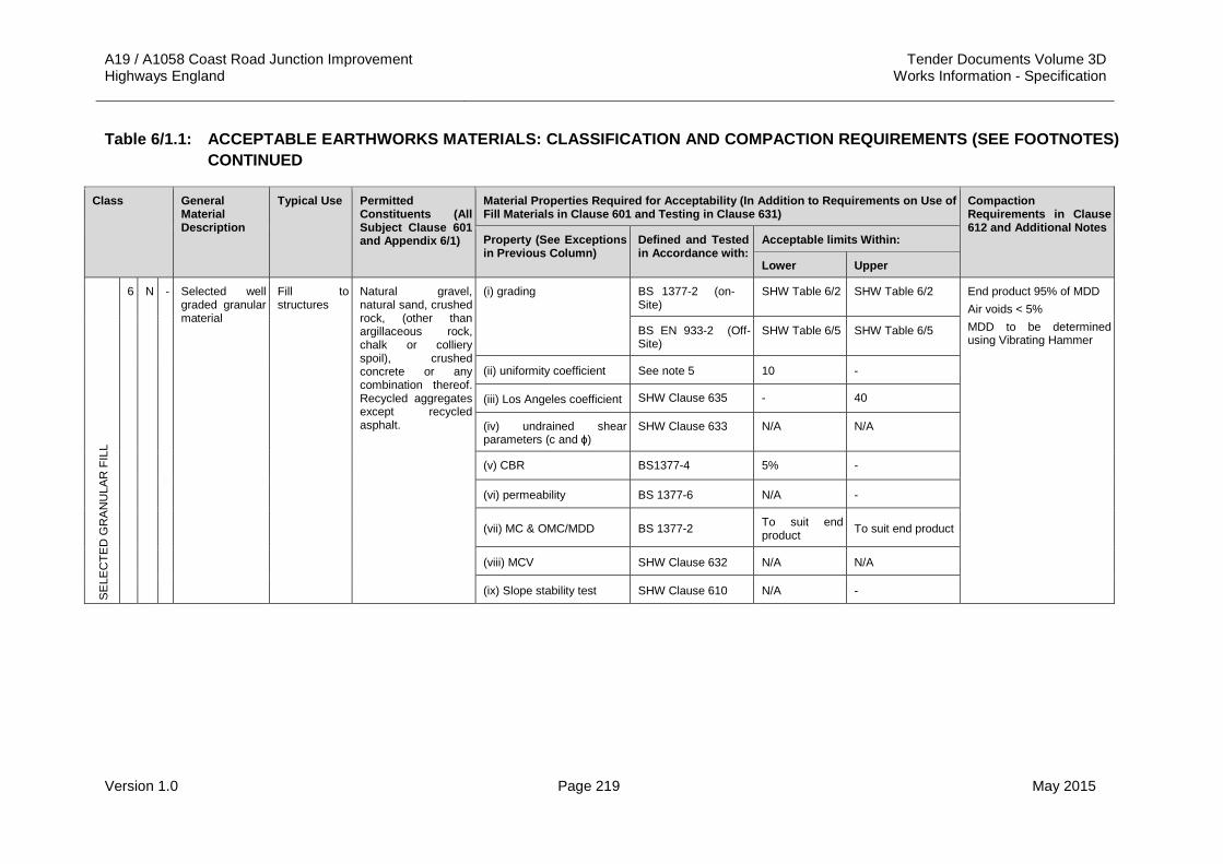
A19 / A1058 Coast Road Junction Improvement Tender Documents Volume 3D Highways England Works Information - Specification
Version 1.0 Page 219 May 2015
Table 6/1.1: ACCEPTABLE EARTHWORKS MATERIALS: CLASSIFICATION AND COMPACTION REQUIREMENTS (SEE FOOTNOTES) CONTINUED
Class General Material Description
Typical Use Permitted Constituents (All Subject Clause 601 and Appendix 6/1)
Material Properties Required for Acceptability (In Addition to Requirements on Use of Fill Materials in Clause 601 and Testing in Clause 631)
Compaction Requirements in Clause 612 and Additional Notes
Property (See Exceptions in Previous Column)
Defined and Tested in Accordance with:
Acceptable limits Within:
Lower Upper
SE
LEC
TED
GR
AN
ULA
R F
ILL
6 N - Selected well graded granular material
Fill to structures
Natural gravel, natural sand, crushed rock, (other than argillaceous rock, chalk or colliery spoil), crushed concrete or any combination thereof. Recycled aggregates except recycled asphalt.
(i) grading BS 1377-2 (on-Site)
SHW Table 6/2 SHW Table 6/2 End product 95% of MDD Air voids < 5% MDD to be determined using Vibrating Hammer
BS EN 933-2 (Off-Site)
SHW Table 6/5 SHW Table 6/5
(ii) uniformity coefficient See note 5 10 -
(iii) Los Angeles coefficient SHW Clause 635 - 40
(iv) undrained shear parameters (c and ɸ)
SHW Clause 633 N/A N/A
(v) CBR BS1377-4 5% -
(vi) permeability BS 1377-6 N/A -
(vii) MC & OMC/MDD BS 1377-2 To suit end product To suit end product
(viii) MCV SHW Clause 632 N/A N/A
(ix) Slope stability test SHW Clause 610 N/A -

A19 / A1058 Coast Road Junction Improvement Tender Documents Volume 3D Highways England Works Information - Specification
Version 1.0 Page 220 May 2015
Table 6/1.1: ACCEPTABLE EARTHWORKS MATERIALS: CLASSIFICATION AND COMPACTION REQUIREMENTS (SEE FOOTNOTES) CONTINUED
Class General Material Description
Typical Use Permitted Constituents (All Subject Clause 601 and Appendix 6/1)
Material Properties Required for Acceptability (In Addition to Requirements on Use of Fill Materials in Clause 601 and Testing in Clause 631)
Compaction Requirements in Clause 612 and Additional Notes
Property (See Exceptions in Previous Column)
Defined and Tested in Accordance with:
Acceptable limits Within:
Lower Upper
SE
LEC
TED
GR
AN
ULA
R F
ILL
6 P - Selected granular material
Fill to structures
Natural gravel, natural sand, crushed rock, (other than argillaceous rock, chalk or colliery spoil), crushed concrete or any combination thereof. Recycled aggregates except recycled asphalt.
(i) grading BS 1377-2 (on-Site)
SHW Table 6/2 SHW Table 6/2 End product 95% of MDD Air voids < 5% MDD to be determined using Vibrating Hammer
BS EN 933-2 (Off-Site) SHW Table 6/5 SHW Table 6/5
(ii) uniformity coefficient See note 5 5 -
(iii) Los Angeles coefficient SHW Clause 635 - 60
(iv) undrained shear parameters (c and ɸ)
SHW Clause 633 N/A N/A
(v) CBR BS1377-4 5% -
(vi) permeability BS 1377-6 N/A -
(vii) MC & OMC/MDD BS 1377-2 To suit end product To suit end product
(viii) MCV SHW Clause 632 N/A N/A
(ix) Slope stability test SHW Clause 610 N/A -

A19 / A1058 Coast Road Junction Improvement Tender Documents Volume 3D Highways England Works Information - Specification
Version 1.0 Page 221 May 2015
Table 6/1.1: ACCEPTABLE EARTHWORKS MATERIALS: CLASSIFICATION AND COMPACTION REQUIREMENTS (SEE FOOTNOTES) CONTINUED
Class General Material Description
Typical Use Permitted Constituents (All Subject Clause 601 and Appendix 6/1)
Material Properties Required for Acceptability (In Addition to Requirements on Use of Fill Materials in Clause 601 and Testing in Clause 631)
Compaction Requirements in Clause 612 and Additional Notes
Property (See Exceptions in Previous Column)
Defined and Tested in Accordance with:
Acceptable limits Within:
Lower Upper
SE
LEC
TED
CO
HE
SIVE
FIL
L
7 A - Selected cohesive material
Fill to structures
Any material, or combination of materials, other than argillaceous rock, chalk or colliery spoil
(i) grading BS 1377-2 SHW Table 6/2 SHW Table 6/2 End product of 100% of MDD of BS1377 Part 4 (2.5kg rammer method) or a dry density corresponding to 5% air voids at field mc whichever is lower.
MDD to be determined using 2.5 kg Rammer and to include measurement of particle density
(ii) MC BS 1377-2 To suit end product
To suit end product
(iii) OMC/MDD/ specific gravity BS 1377-2
(iv) effective shear strength parameters (c’ and ɸ’)
SHW Clause 636 c’ = 0 ɸ’ = 35
-
(vi) liquid limit BS 1377-2 - 70
(vii) plasticity index BS 1377-2 - 45

A19 / A1058 Coast Road Junction Improvement Tender Documents Volume 3D Highways England Works Information - Specification
Version 1.0 Page 222 May 2015
Table 6/1.1 FOOTNOTES
1. App = Appendix
2. Tab = Table
3. Where in the Acceptable Limits column reference is made to App 6/1, only those properties having limits ascribed to them in Appendix 6/1 shall apply. Where Appendix 6/1 gives limits for other properties not listed in this Table such limits shall also apply.
4. Where BS 1377: Part 2 is specified for mc, this shall mean BS 1377: Part 2 or BS EN 1097-5 as appropriate.
5. Uniformity coefficient is defined as the ratio of the particle diameters D60 to D10 on the particle-size distribution curve, where: D60 = particle diameter at which 60% of the soil by weight is finer and D10 = particle diameter at which 10% of the soil by weight is finer.
6. The limiting values for Class U1B material are given in Appendix 6/14 and Appendix 6/15.
7. Where undrained shear strength is specified as the method of acceptability testing, the Contractor may use a hand vane provided that it is initially calibrated against the unconsolidated undrained shear strength laboratory triaxial test to BS 1377:Part 7, clause 8 on 100mm nominal diameter samples, and the MCV test in accordance with BS 1377:Part 4. Otherwise, shear strength testing requirements is to be as set out in Clause 633 of the Specification for Highways Works.
8. The contents of this table may be revised following periodic engineering assessments and design by the Project Manager.
9. Where supplementary clauses and tables are reference in Table 6/1.1 above, they shall refer to the equivalent clause or table from the Specification for Highway Works.

A19 / A1058 Coast Road Junction Improvement Tender Documents Volume 3D Highways England Works Information - Specification
Version 1.0 Page 223 May 2015
Table 6/1.2: Grading Requirements for Acceptable Earthworks Materials Other Than Classes 6F4, 6F5 and 6S
Percentage by Mass Passing the Size Shown
Class Size (mm) Size (mm) BS Series
Size (microns) BS Series
Size (µm)
Clas
s
500 300 200 125 90 75 37.5 28 20 14 10 6.3 5 3.35 2 1.18 600 300 150 63 2
1A 100 95 - 100
<15 1A
1B 100 <15 1B
1C 100 10 - 95
0 - 25 <15 1C
2A & 2B
100 80 - 100 15 - 100
2A & 2B
2C 100 15 - 80 15 - 80
2C
6F1 100 75 - 100
40 - 95
30 - 85
10 - 50
<15 6F1
6F2 100 80 - 100
65 - 100
45 - 100
15 - 60
10 - 45
0 - 25
0 - 12 6F2
6F3 100 80 - 100
65 - 100
45 - 100
15 - 60
10 - 45
0 - 25
0 - 12 6F3
6N & 6P
100 <15 6N & 6P
7A 100 15 - 100
7A & 7A

A19 / A1058 Coast Road Junction Improvement Tender Documents Volume 3D Highways England Works Information - Specification
Version 1.0 Page 224 May 2015
Table 6/1.3: Grading Requirements for off-Site Class 6 Acceptable Earthworks Materials
Percentage by Mass Passing the Size Shown
Class Size (mm) Size (mm) BS EN 933-2 Series
Size (microns) BS EN 933-2 Series
Class
500 300 125 80 63 40 31.5 20 16 10 8 6.3 4 2 1 500 250 125 63
6F4 100 75 - 99
50 - 90
30 - 75
15 - 60
0 - 35
<15 6F4
6F5 100 75 - 99
50 - 90
30 - 75
15 - 60
0 - 35 0 - 12 6F5

A19 / A1058 Coast Road Junction Improvement Tender Documents Volume 3D Highways England Works Information - Specification
Version 1.0 Page 225 May 2015
APPENDIX 6/2: REQUIREMENTS FOR DEALING WITH CLASS U1B AND CLASS U2 UNACCEPTABLE MATERIALS
1. General 1.1 Class U1B material may be encountered across the Site and no such
materials shall be incorporated into the Works.
1.2 No U2 materials have been identified on the Site at the time of Tender. The Contractor shall notify the Project Manager immediately of any such materials.
1.3 Suspected Class U1B and U2 materials shall be stockpiled separately with an impermeable geo-synthetic layer at its base prior to disposal off Site.
1.4 Potentially contaminated and contaminated stockpile areas shall be provided with a suitable water run-off collection system to ensure contaminated waters do not impact the Site or the wider environment.
1.5 All wastes shall be handled, transported and disposed of in accordance with the appropriate legislation.
2. Methods of Excavation, Precautions and Requirements for Handling 2.1 Conventional excavation methods shall be appropriate for the proposed
Works with the exception of potential Class U1B and U2 materials.
2.2 Where ground workers shall be handling potentially contaminated materials they shall wear appropriate personal protective equipment.
2.3 There are no special requirements for dealing with leachate and contaminated water at the time of Tender.
2.4 There are no requirements for special drainage and for sealing exposed surfaces of contaminated materials at the time of Tender.
3. Test Methods for Chemical Analysis 3.1 The Contractor shall refer to the tests scheduled in Appendix 1/5 of this
Specification.
3.2 All soil and groundwater laboratory testing shall be undertaken at a UKAS and MCERTS accredited laboratory.

A19 / A1058 Coast Road Junction Improvement Tender Documents Volume 3D Highways England Works Information - Specification
Version 1.0 Page 226 May 2015
APPENDIX 6/3: REQUIREMENTS FOR EXCAVATION, DEPOSITION, COMPACTION (OTHER THAN DYNAMIC COMPACTION)
1. Earthwork requirements are shown on the earthwork drawings listed in Appendix 0/4 of this Specification.
2. No blasting shall be permitted in this Contract.
3. Cutting faces 3.1 The Contractor shall comply with the requirements of Clause 603 of the
Specification for Highways Works when carrying out any excavation works.
3.2 The Contractor shall not clear loose material from areas not requiring topsoil with an airline hose in this Contract.
3.3 The Contractor shall make all excavation faces stable in accordance with the requirements of Clause 603 of the Specification for Highways Works.
3.4 There are no requirements to protect excavation faces comprising soft or insecure materials interlayered with rock in areas not requiring topsoil in the Contract at the time of Tender.
3.5 The Contractor shall propose in his method statement which of the measures in Clause 603.7 he shall adopt to make good areas prior to Topsoiling.
4. Watercourses 4.1 Proposed and existing watercourses and their treatment are shown on the
Drainage Layout plans included in Appendix 0/4 of this Specification.
4.2 There are no watercourses to be made redundant included in this Contract at the time of Tender.
5. Embankment Construction 5.1 Filling shall be carried out at no steeper than 1v:2h in the permanent
condition with no increase in width.
5.2 There is no requirement for the staged construction of fills in the Contract at the time of Tender.
5.3 There is no requirement to surcharge the embankments in the Contract at the time of Tender.
5.4 The minimum thickness of capping or sub-base materials to protect the sub-formation or formation layer shall be 300 mm.
5.5 There is no requirement for a starter layer in the Contract at the time of Tender.
6. Compaction 6.1 There is no requirement for a compaction trial in this Contract at the time of
Tender.
6.2 A nuclear surface density gauge shall be permitted for assessing the compaction status of earthworks materials.
6.3 The compaction and field dry density tests shall be carried out at the frequency stated in Appendix 1/5 of this Specification.

A19 / A1058 Coast Road Junction Improvement Tender Documents Volume 3D Highways England Works Information - Specification
Version 1.0 Page 227 May 2015
6.4 The Contractor shall supply the compaction and field dry density test results to the Project Manager as they become available. They shall be submitted in both paper and digital formats in accordance with the requirements of BS 1377.
8. ExcavationsLocations of excavations are shown on the earthworks drawings listed in Appendix 0/4 of this Specification.
8.2 The typical width of bench in excavations shall be 1 m. The bench height shall be determined according the nature of the existing materials but shall not exceed 0.5 m. Each bench shall slope such that water freely drains off the bench and the back of the bench shall be at an angle of 10º less than vertical into the material being excavated.
8.3 The Contractor shall ensure that all surfaces excavated to formation level shall be surveyed for inclusion in the as-built records.
8.4 If material at the formation level shall be assessed by the Project Manager to be unsuitable as a formation layer then the material shall be excavated and disposed of to tip off-Site. Following the removal of any such unsuitable materials the Contractor shall survey the excavation and the volume of material removed shall be recorded prior to placement and compaction of acceptable fill material.
8.5 The Contractor shall maintain an accurate record of the volume of excavated material for the duration of the Works.
9. The fill to the corrugated steel buried structure at Middle Engine Lane shall comply with Clause 623 of the Specification for Highways Works.
10. There is no requirement for the mixing of acceptable and unacceptable materials revealed in excavations in the Contract at the time of Tender.
11. There is no requirement to fill excavated voids or natural voids in excavations for foundations in the Contract at the time of Tender.
12. The contractor shall refer to the General Arrangement of the Middle Engine Lane bridge widening drawing (Ref: A19T-DWG-CIV-2000-0008) for any additional requirements for corrugated steel buried structures.

A19 / A1058 Coast Road Junction Improvement Tender Documents Volume 3D Highways England Works Information - Specification
Version 1.0 Page 228 May 2015
APPENDIX 6/6: FILL TO STRUCTURES AND FILL ABOVE STRUCTURAL FOUNDATIONS
1. The fill to structures is shown on the drawings listed in Appendix 0/4 of this Specification.
2. The fill material used shall be Class 6N or 6P and comply with the requirements of Table 6/1.1 of this Specification.
3. The Contractor shall comply with the requirements of Clause 623 of the Specification for Highways Works for the fill to the corrugated structure that shall be used to widen Middle Engine Lane.

A19 / A1058 Coast Road Junction Improvement Tender Documents Volume 3D Highways England Works Information - Specification
Version 1.0 Page 229 May 2015
APPENDIX 6/7: SUB-FORMATION AND CAPPING AND PREPARATION AND SURFACE TREATMENT OF FORMATION
1. The location of where capping and / or sub-base materials shall be required is shown on the pavement layout drawings (Ref: A19T-DWG-CIV-S00-0700-0001 to 0004 inclusive).
2. The surface tolerances shall be in accordance with Clause 616 of the Specification for Highways Works.
3. Capping material shall be Class 6F2 or 6F5 of this Specification.
4. The Contractor shall conduct CBR compliance testing of the sub-grade at 100 m intervals. Where the CBR is shown to be less than the design CBR then the thickness and type of capping and / or sub-base shall be increased as instructed by the Project Manager.
5. There is no requirement for a demonstration area for capping material included in the Works at the time of Tender.
6. The sub-formation shall be shaped in accordance with the requirements of Clause 613.8 of the Specification for Highways Works.
7. Lime stabilisation of existing sub-grade materials shall not be used in the Works.
8. There are no areas where the requirements of Clause 616.4 shall be required known at the time of Tender.
9. There is no requirement to prepare an existing sub-base material as a formation layer in the Contract at the time of Tender.
10. Exposed areas of sub-formation and formation shall be kept to a minimum and shall be covered as quickly as practicable to avoid deterioration. Surface water shall be kept off exposed areas by use of drainage measures.
11. Exposed areas of sub-formation and formation shall not be used as haulage routes.
12. Soft spots shall be defined as subgrade material having a CBR value less than 2%. Where encountered the Contractor shall excavate the soft spot until the required CBR is achieved. The excavated void shall be filled with capping material in compliance with this Specification.
13. Final preparation of the sub-formation shall be carried out after the execution and completion of the sub-grade drainage at that location. The sub-formation and / or formation shall be shaped and trimmed by the minimum amount necessary to ensure water does not pond prior to placement of capping and / or sub-base materials. If necessary the Contractor shall provide temporary drainage measures to keep the sub-formation and / or formation free from ponding water.

A19 / A1058 Coast Road Junction Improvement Tender Documents Volume 3D Highways England Works Information - Specification
Version 1.0 Page 230 May 2015
APPENDIX 6/8: TOPSOILING 1.1 The location and depth where topsoil shall be stripped shall be as shown on
the earthworks drawings listed in Appendix 0/4 of this Specification.
1.2 Topsoil shall be stockpiled in accordance with the requirements of Clause 602.10 of the Specification for Highways Works at locations within the Site boundaries to suit the Contractors operations.
1.3 Any surplus topsoil after completion of the finished layer of topsoil to all areas within the Site shall be stockpiled in accordance with Clause 602.10 of the Specification for Highways Works in a location to be agreed with the Project Manager.
1.4 There are no requirements for slopes of Class 2E and 7B fill material included in the Works at the time of Tender.
1.5 The Contractor shall comply with the requirements of Clause 618 of the Specification for Highways Works during the placement of topsoil.
1.6 The Contractor shall provide a finished layer of topsoil 100 mm thick across the Site.

A19 / A1058 Coast Road Junction Improvement Tender Documents Volume 3D Highways England Works Information - Specification
Version 1.0 Page 231 May 2015
APPENDIX 6/12: INSTRUMENTATION AND MONITORING 1 The details of monitoring instrumentation are detailed within the
Geotechnical Interpretative Report which is supplied as part of the Site Information and summarised in Table 6/12.1.
2 All monitoring of geotechnical instrumentation shall be undertaken by the Overseeing Organisation.
Table 6/12.1: Instrumentation and Monitoring Requirements
Instrument Type
Number Format Frequency Notes
Settlement plates (rod extensometers)
2 No. every 50m
Plots of change in vertical position against time
Weekly from two weeks (minimum) before commencement of construction of the embankment. Daily during and for a period of one month following completion of embankment construction. Fortnightly between one month and six months post completion of embankment construction.
Measurement shall be by the use of a precise level with an accuracy of 0.1mm
Vibrating wire piezometers
3 No. every 50m
Plots of piezometric level against time
Continuous from two weeks (minimum) before commencement of construction. Continuous until six months post completion of embankment construction.
Response zone in superficial deposits/ alluvium.
Inclinometers 2 No. every 50m
Plot of cumulative deflection against time
Weekly from two weeks (minimum) before commencement of construction. Daily during and for a period of one month following completion of embankment construction. Fortnightly between one month and six months post completion.
3 All monitoring instrumentation shall be installed, serviced and decommissioned by the Contractor in accordance with the guidance and requirement of the product’s manufacturer specification and this Appendix, at least two weeks prior to the commencement of construction of the embankments.
4 The location of the required monitoring instrumentation is shown on Drawing No. A19T-DWG-CIV-S00-0600-0001 to 0004 inclusive.

A19 / A1058 Coast Road Junction Improvement Tender Documents Volume 3D Highways England Works Information - Specification
Version 1.0 Page 232 May 2015
6 Vibrating wire piezometers shall be installed by means of boreholes and / or in-situ Cone Penetration Tests (CPTs), to a minimum depth of 15 m, with the response zones of the instrumentation being within the superficial deposits/alluvium.
7 The installation of the instruments shall be supervised by the Supervisor, who shall confirm the details of the installations required. The method(s) of installation shall be submitted to the Project Manager for approval at least two weeks (minimum) prior to the commencement of the installations. The installation and calibration requirement shall be in accordance with the product’s manufacturer specification.
8 The data recorder for the vibrating wire piezometers shall be protected by a waterproof container above ground level. The location of the waterproof container shall be confirmed on site with the Project Manager during installation. The selected product shall be approved by the Project Manager at least two weeks prior to the installation of the soil instruments.
9 Inclinometers shall be installed by means of boreholes and / or in-situ Cone Penetration Tests to a minimum depth of 15 m below the formation level within boreholes. The installation of the instruments shall be supervised by the Supervisor, who shall confirm the details of the installations required. The method(s) of installation shall be submitted to the Project Manager for approval at least two weeks prior to the commencement of the installations. The boreholes shall be secured by a cast iron cover, which shall be raised to a minimum of 0.3 m above the existing ground level.
10 All monitoring instrument locations shall be marked up and protected by the Contractor prior to the commencement of construction. The method of protection of the monitoring instruments shall be submitted to the Project Manager for approval at least one week prior to the commencement of construction.
11 The frequency and duration of monitoring is summarised in Table 6/12.1.
12 All monitoring shall be undertaken by the Supervisor in accordance with the specified frequency and duration in Table 6/12.1. The results shall be supplied in both hardcopy and electronic format to the Project Manager daily / on request for assessment.

A19 / A1058 Coast Road Junction Improvement Tender Documents Volume 3D Highways England Works Information - Specification
Version 1.0 Page 233 May 2015
APPENDIX 6/14: LIMITING VALUES FOR POLLUTION OF CONTROLLED WATERS
1 The limiting values for pollution of controlled waters shall be as presented in Table 6/14.1.
Table 6/14.1: Concentration Limits for Pollution of Controlled Waters
Analyte Leached concentration (mg/kg)
Aluminium 200
Antimony 5
Arsenic 10
Barium 1000
Boron 1000
Cadmium 5
Chromium (3) 50
Chromium (6) 50
Chromium (total) 50
Copper 2000
Iron 200
Lead 25
Magnesium 5000
Manganese 50
Mercury 1
Nickel 20
Potassium 12000
Selenium 10
Silver 10
Total PAH 0.1
Benzo (a) pyrene 0.01
Dissolved hydrocarbons 10
Cyanide (total) 50
2 Limits presented in Table 6/14.1 are derived from UK Drinking Water Standards, dated 2001 generic assessment criteria published by DEFRA.
3 Testing requirements for Site won and imported materials are scheduled in Appendix 1/5.

A19 / A1058 Coast Road Junction Improvement Tender Documents Volume 3D Highways England Works Information - Specification
Version 1.0 Page 234 May 2015
APPENDIX 6/15: LIMITING VALUES FOR HARM TO HUMAN HEALTH AND THE ENVIRONMENT
1 The limiting values for harm to Human Health and the Environment shall be as presented in Tables 6/15.1 and 6/15.2.
Table 6/15.1: Metals and Inorganics
Determinant Concentration (mg/kg)
Source of Assessment
Arsenic 640 CLEA SGV
Beryllium 420 WSPE GAC
Boron 190000 WSPE GAC
Cadmium 230 CLEA SGV
Chromium (III) 30000 WSPE GAC
Chromium (IV) 35 WSPE GAC
Copper 72000 WSPE GAC
Cyanide 60 WSPE GAC
Lead 6013 WSPE GAC
Elemental Mercury 26 CLEA SGV
Inorganic Mercury 3600 CLEA SGV
Methyl Mercury 410 CLEA SGV
Nickel 1800 CLEA SGV
Selenium 13000 CLEA SGV
Vanadium 3200 WSPE GAC
Tin 43000 WSPE GAC
Zinc 660000 WSPE GAC
Table 6/15.2: Organics
Determinant Assessment Criteria (mg/kg)
Source of Assessment Criteria
TPH
Aliphatics C5-C6 3400 RISC 4
Aliphatics >C6-C8 8300 RISC 4
Aliphatics >C8-C10 2100 RISC 4
Aliphatics >C10-C12 10000 RISC 4
Aliphatics >C16-C21 1600000 RISC 4
Aliphatics >C21-C34 1600000 RISC 4
Aromatics >C5-C7 28000 RISC 4
Aromatics >EC8-EC10 3700 RISC 4
Aromatics >EC10-EC12 17000 RISC 4

A19 / A1058 Coast Road Junction Improvement Tender Documents Volume 3D Highways England Works Information - Specification
Version 1.0 Page 235 May 2015
Table 6/15.2: Organics Continued
Determinant Assessment Criteria (mg/kg)
Source of Assessment Criteria
TPH
Aromatics >EC12-EC16 36000 RISC 4
Aromatics >EC16-EC21 28000 RISC 4
Aromatics>EC21-EC35 28000 RISC 4
BTEX Suite
Benzene 28 CLEA SGV
Toluene 59000 CLEA SGV
Ethylbenzene 17000 CLEA SGV
m, p & o – xylene 6500 CLEA SGV
PAH Suite
Naphthalene 200 RISC 4
Acenaphthylene 84000 RISC 4
Acenaphthene 85000 RISC 4
Fluorene 64000 RISC 4
Phenanthrene 22000 RISC 4
Anthracene 520000 RISC 4
Fluoranthene 23000 RISC 4
Pyrene 54000 RISC 4
Total PAH - -
2 The limits in Tables 16/15.1 and 6/15.2 have been derived from generic guideline values produced either by DEFRA soil guidelines values (CLEA SGV), or WSPE generated values (GAC for metals and inorganics, and RISC 4 for organics). Both assume a commercial/industrial exposure scenario as this is considered the most applicable to the Site operations.
3 Testing requirements for Site won and imported materials are scheduled in Appendix 1/5.

A19 / A1058 Coast Road Junction Improvement Tender Documents Volume 3D Highways England Works Information - Specification
Version 1.0 Page 236 May 2015
APPENDIX 7/1: PERMITTED PAVEMENT OPTIONS 1. General 1.1 The locations of the different pavement options are shown on drawings
A19T-DWG-CIV-S00-0700-0001 to 0004 inclusive.
1.2 The pavement designs have been based on certain assumed CBR values. Please refer to Appendix 6/7 for details on the procedure for more accurate determination of the CBR.
1.3 The pavement design has been based on a Restricted Foundation Design as outlined in Chapter 3 of Interim Advice Note (IAN) 73/06 Rev 01.
1.4 Summary information of the Surfacing Requirements for the scheme is contained in Table 7/1.1.
2. Design Standards 2.1 This Pavement Designs have been undertaken in accordance to the Design
Manual for Roads and Bridges (DMRB) current on the Tender date.
(i) Interim Advice Note 73/06 Rev01 (Foundation Design).
(ii) HD 26/06 (Pavement Design).
(iii) HD 36/06 (Surfacing Materials for New and Maintenance Construction).
(iv) Interim Advice Note 156/12 Revision of Aggregate Specification for Pavement Surfacing.

A19 / A1058 Coast Road Junction Improvement Tender Documents Volume 3D Highways England Works Information - Specification
Version 1.0 Page 237 May 2015
Table 7/1.1: Pavement Design Summary Information
Surface Requirements
Road Name Million Standard Axles (msa)
Traffic (cv/lane/day) Site Category IL Min.
PSV Max. AAV
Stress Level In 2018 At Design Life (2038)
A19 Mainline NB and SB 105 - 105 B2 0.35 60 14 1
A19 SB Merge Slip - - - B2 0.35 60 14 1
A19 NB Merge Slip - - - B2 0.35 60 16 1
A19 SB Diverge Slip - - - Q 0.45 60 16 1
A19 NB Diverge Slip - - - B2 0.35 60 16 1
The Silverlink - - - Q 0.45 60 16 1
Notes: a. The Minimum Stated Level of PSV is for the main carriageways except for on the approaches to junctions. For junction approaches the minimum
required PSV shall be 65. b. Traffic data provided by Arup’s for peak flows c. cv growth rate used is based on HD 24/06 Rev 01 d. Traffic (cv/l/d) calculated by ascertaining the average peak flows for AM and PM and multiplying by 24. Growth rate applied as above to achieve
traffic at design life. e. Investigatory Level (IL) is taken from HD 28/04 f. Minimum PSV is based on HD36/06 g. Maximum AAV is based on HD 36/06 h. HFS to be applied on the approach to Pedestrian Crossings.

A19 / A1058 Coast Road Junction Improvement Tender Documents Volume 3D Highways England Works Information - Specification
Version 1.0 Page 238 May 2015
3. Permitted Pavement Options – Schedule 1 3.1 Flexible Construction will be the only permitted option.
3.2 The design of new trunk road and widened trunk road pavements has been developed to provide a 40 year design life.
3.3 The Contractor shall take core samplings and tests of existing pavements that will become part of the permanent Works to determine whether they will provide a 20 year residual life.
3.4 The pavement designs have been based on a restricted foundation.
Schedule 1 – Permitted Pavement Options
Drawing Ref: Area General Requirements Permitted Pavement Options
A19T-DWG-CIV-S00-0700-0001 to 0004 1 Schedule 2 P1 P2 P3 P4 NW1 NW2 FW1
4. General Requirements – Schedule 2 Schedule 2 – General Requirements
Grid for checking surface levels of pavement courses (Cl 702.4)
Longitudinal Dimension: 10 m
Transverse Dimension: 2 m
Surface Regularity (Cl 702.5, Table 7/2) Category of Road: A
Interval for Measurement of Longitudinal Regularity (Cl 702.7): 300m
Interval for Measurement of Transverse Regularity (Cl 702.8): 10m
5. Permitted Construction Materials – Schedule 3 Schedule 3 – Permitted Construction Materials
Pavement Option P1 Pavement Option P2
Pavement Layer Material Ref. Thickness (mm) Material Ref. Thickness
(mm)
Surface Treatment - - HFS1 N/A
Surface Course SC1* 40 SC1* 40
Binder Course BC1 60 BC1 60
Upper Base RBU1 110 RBU1 90
Lower Base RBL1 110 RBL1 90
Sub-Base SB1 340** SB1 340**
Total Thickness 660 620
Capping Capping Not Required Capping Not Required * On the approach to junctions, material to have a minimum of 65 PSV ** Based on a Class 3 Foundation on a Sub-grade of 2.5% CBR.

A19 / A1058 Coast Road Junction Improvement Tender Documents Volume 3D Highways England Works Information - Specification
Version 1.0 Page 239 May 2015
Schedule 3 – Permitted Construction Materials Continued
Pavement Layer
Pavement Option P3 Pavement Option P4
Material Ref. Thickness (mm) Material Ref. Thickness
(mm)
Surface Treatment - - HFS1 N/A
Surface Course SC1* 40 SC1* 40
Binder Course BC2 80
Total Thickness 120 40 * On the approach to junctions, material to have a minimum of 65 PSV
Pavement Layer
Pavement Option NW1 Pavement Option NW2
Material Ref. Thickness (mm) Material Ref. Thickness
(mm)
Surface Treatment - - - -
Surface Course SC1* 40 SC1* 40
Binder Course BC1 60 BC1 60
Base ST5 200
Total Thickness 300 100 * On the approach to junctions, material to have a minimum of 65 PSV
Pavement Layer
Pavement Option FW1
Material Ref. Thickness (mm)
Surface Course SC1 20
Binder Course BC1 50
Total Thickness 70
6. General Requirements for Construction Materials – Schedule 4 6.1 Unless otherwise stated in Schedule 4 below, all other general requirements for
construction materials shall be as per Series Clauses 800 and 900 of the SHW.
Schedule 4 – General Requirements for Construction Materials
Clause Requirement
801.2 The Limiting distance for deposition of unbound mixtures shall be as described in sub-Clause 801.2 of the SHW
801.3 The Limiting distance for deposition of unbound mixtures shall be as described in sub-Clause 801.3 of the SHW
801.7 All materials within 450mm of the final finished road level shall be non- frost susceptible.
903.4 All Thin Surface Course Systems require the use of a Bond Coat as described in sub-Clause 903.4

A19 / A1058 Coast Road Junction Improvement Tender Documents Volume 3D Highways England Works Information - Specification
Version 1.0 Page 240 May 2015
7. Requirements for Construction Materials – Schedule 5 Schedule 5 – Requirements for Construction Materials
Material Ref:
Clause Description Requirement
Sub-Clause Specification
HFS1 924 High Friction Surfacing
924.3 and Table NG 9/4
Type Classification: Type 1
924.4 Required declared PSV category: HFS
924.4 Required maximum AAV category: 14
Colour shall be Grey / Black
SC1 942
Thin Surface Course Systems (TSCS)
942.1 A19 SB: cv/l/d – 1705 A19 NB: cv/l/d - 1414
942.1 and Table NG 9/27
Mainline and Merge Slip Roads are Site Category B2 and Stress Level 1. Diverge Slip Roads are Site Category Q and Stress Level 1. Roundabout is Site Category R and Stress Level 3.
942.5 Minimum PSV shall be 55 on all roads and 65 on all approaches to roundabouts and junctions.
942.5
Maximum AAV value for coarse aggregates shall be 14 on the Mainline and Slip Roads. Maximum AAV value of coarse aggregates shall be 16 on the Roundabout.
942.7 Resistance to permanent deformation shall be Level 3.
942.8 and Table NG 9/30
Road Tyre Noise Level shall be Level 3 (- 3.5 dB(A))
921.1 Surface Macro-texture measures are required – minimum value shall be 1.3mm.
SC8 942
Fuel Resistant Surface Course System
Surface course system needs to be fuel resistant for use in lay-bys.
942.5 Minimum PSV shall be 60
942.5 Maximum AAV value of coarse aggregates shall be 16.
921.1 Surface Macro-texture measures are required – minimum value shall be 1.5mm.

A19 / A1058 Coast Road Junction Improvement Tender Documents Volume 3D Highways England Works Information - Specification
Version 1.0 Page 241 May 2015
Schedule 5 – Requirements for Construction Materials Continued
Material Ref:
Clause Description Requirement
Sub-Clause Specification
BC1 906
Dense Binder Course Asphalt Concrete (Recipe Mixtures)
906.1
Mixture Designation shall be: • AC 20 dense bin 40/60 rec.
BC2 904 Hot Rolled Asphalt Base 904.1
Mixture Designation shall be:
• HRA 60/32 base 30/45
RBU1 906
Dense Base Asphalt Concrete (Recipe Mixtures)
906.1
Mixture Designation shall be: • AC 32 dense bin 40/60 rec.
RBU1 906
Dense Base Asphalt Concrete (Recipe Mixtures)
906.1
Mixture Designation shall be: • AC 32 dense bin 40/60 rec.
SB1 803 Type 1 Unbound Mixture
803.1 Permitted mixtures shall be limited to Crushed Rock
803.8 Minimum CBR required is 10%
FSB1 for use in Footways Only. SB1 to be used elsewhere.
FSB1 803 Type 1 Unbound Mixture
803.1 Permitted mixtures shall be limited to Crushed Rock
803.8 Minimum CBR required is 10%
FSB1 for use in Footways Only. SB1 to be used elsewhere.
ST5 ST5 No Fines Concrete
8. Thin Surface Course Systems: Information to be Provided by the Contractor – Schedule 6
8.1 The Contractor shall provide the following information before any paving Works commence:
(i) A copy of the British Board of Agrement, Highways England Product Approval System Certificate (formerly known as HAPAS) or Certificates for the This Surface Course System or systems that are proposed for use in the works, together with a copy of the Installation Method Statement associated with each certificate.
(ii) For any Certificate that covers several variants of one Thin Surface Course System, proposed variant or variants of the system to be used in the Works.

A19 / A1058 Coast Road Junction Improvement Tender Documents Volume 3D Highways England Works Information - Specification
Version 1.0 Page 242 May 2015
(iii) If requested, or if the Thin Surface Course System is not produced under a Sector Scheme, the proposed component materials to be used in the Thin Surface Course System and their proportions for each proposed system.
(iv) Proposed source of sources of coarse aggregate together with a statement of properties including Polished Stone Value, Aggregate Abrasion Value, Los Angeles Coefficient and Flakiness index.
(v) If regulating material is to be used, evidence of its deformation resistance either independently or in combination with the Thin Surface Course System.
9. Binder Data Requirements – Schedule 7 9.1 The following for modified binders as required in sub-Clauses 937.4 and
943.4 shall be provided by the Contractor and made available upon request. The data should not be more than 12 months old. A table in which the binder data may be recorded is given at the end of this section.
Binder Samples
9.2 Bituminous binders shall be sampled from the delivery according to BS EN 58. For modifiers blended with the other component materials of the mixture at the mixer, a simulated binder shall be prepared. Such modifiers are generally less intimately mixed with the bitumen and less well dispersed throughout the mixture than when pre-blended. Evidence that that simulated binder offers the same performance as the binder produced when the modifier is added at the mixer shall be provided.
Penetration
9.3 Binder penetration at 25oC (BS EN 1426), 100g 5 seconds, and at 5oC, 200g 60 seconds, before and after hardening in the Rolling Thin Film Oven Test (RTFOT) in accordance with BS EN 12607-1, or alternatively, after RTFOT and after RTFOT and Ageing in accordance with Clause 955.
Product Identification Test and Rheological Properties
9.4 Binder penetration at 25oC (BS EN 1426), 100g 5 seconds, and at 5oC, 200g 60 seconds, before and after hardening in the Rolling Thin Film Oven Test (RTFOT) in accordance with BS EN 12607-1, or alternatively, after RTFOT and after RTFOT and Ageing in accordance with Clause 955.
Storage Stability Test
9.5 All binders shall be stored strictly in accordance with the manufacturer’s instructions. Polymer modified binders claimed to remain homogenous in storage without agitation shall be tested for storage stability in the manner described in Clause 958. The mean of the differences in softening point between the top and bottom samples, of not less than five pairs of such samples, shall not exceed 5oC. Manufacturers of pre-blended modified binders shall state what precautions are necessary to ensure that adequate homogeneity is maintained during storage.

A19 / A1058 Coast Road Junction Improvement Tender Documents Volume 3D Highways England Works Information - Specification
Version 1.0 Page 243 May 2015
Photomicrograph
9.6 A typical photomicrograph of the modified binder and binder using ultra-violet or other technique to provide maximum contrast of the polymer structure to the binder before modification shall be supplied together with details of sample preparation techniques.
Cohesion
9.7 Vialit Pendulum cohesion test curve of the binder, in accordance with Clause 957 for the binder as supplied, after RTFOT and after RTFOT and Ageing in accordance with Clause 955.
FRAASS Brittle Point
9.8 FRAASS brittle point measured using BS EN 12593 shall be provided on the binder as supplied, after RTFOT and after RTFOT and Ageing in accordance with Clause 955.

A19 / A1058 Coast Road Junction Improvement Tender Documents Volume 3D Highways England Works Information - Specification
Version 1.0 Page 244 May 2015
Summary of Binder Data
Materials Details:
Manufacturer of Binder:
Product Name:
Binder Type: Batch Ref:
Binder Source:
Softening Point Difference in Storage Stability Test:
Test: Supplied Binder:
After RTFOT After Ageing
Penetration at 25oC 0,1mm (100g and 5 secs)
Penetration at 5oC 0,1mm (200g and 60 secs)
Vialit pendulum cohesion (see Clause 939), maximum peak value J/cm2
# # #
Product Identification Test # # #
Complex Shear (stiffness) modulus (G*) and phase angle (∂) data. See Clause 928
FRAASS Brittle Point
Other properties the Contractor considers useful:
Where indicated with an # the Contractor shall attach a graphical output to this schedule.
10. Mixture Data Requirements – Schedule 8 10.1 The Contractor should assemble the following data and be make them
available on request for materials designed in accordance with Clause 901.17 and Clause 929 in respect of the proposed mixture Saturation Ageing Tensile Stiffness (SATS) ratio – as described in Clause 953.
10.2 For work carried out for the Highways England, a copy of the results should be handed to the Project Manager, to be forwarded to: Pavement Engineering Team at Highways England, Woodlands, Manton Lane, Manton Industrial Estate, Bedford, MK41 7LW.
I. Saturation ageing tensile Stiffness (SatS) ratio – as described in Clause 953

A19 / A1058 Coast Road Junction Improvement Tender Documents Volume 3D Highways England Works Information - Specification
Version 1.0 Page 245 May 2015
APPENDIX 7/2: EXCAVATION, TRIMMING AND REINSTATEMENT OF EXISTING SURFACES
1. Any existing paved surfaces that are not being amended by the Works Information, but require the excavation of a trench or trial pit shall be reinstated in accordance with Drawing Number A19T-DWG-CIV-S00-0700-0001 to 0004 inclusive.
2. The material used for reinstatement will be agreed before reinstatement work commences and will depend on the location of the reinstatement.
3. The use of asphalt reinforcement in permanent trench reinstatement Works shall be agreed with the Contractor’s Design Representative before any such work commences. The asphalt reinforcement shall be Glasgrid 6502 or similar approved.
4. The Contractor shall carry out all permanent reinstatement of excavations opened by Statutory Undertakers or others in the course of their diversionary Works in areas of carriageway or paved areas which are to be subsequently overlaid.
5. Before any overlaying or trimming of existing surfaces is carried out, the Contractor shall ensure that:
(i) All existing road studs shall be taken up and assessed for their potential to be reused. See the details in Appendix 2/3.
(ii) All existing channels shall be thoroughly cleaned and any vegetation encroaching onto the carriageway shall be removed or else restricted from encroaching onto the carriageway.
(iii) The surface shall be mechanically swept and any debris or surplus material shall be removed to an off Site tip.
(iv) A tack coat or bond coat shall be applied where necessary before any new pavement layer is constructed.
6. The construction detail for joints between bituminous surfacing can be seen on Drawing A19T-DWG-CIV-S00-0700-0001 to 0004 inclusive.

A19 / A1058 Coast Road Junction Improvement Tender Documents Volume 3D Highways England Works Information - Specification
Version 1.0 Page 246 May 2015
APPENDIX 7/4: BOND COATS, TACK COATS AND OTHER BITUMINOUS SPRAYS
1.1 Tack Coat shall be used in all locations where a new pavement layer is to be constructed on top of an existing pavement layer or other road construction (e.g. concrete). These are shown on the pavement drawings A19T-DWG-CIV-S00-0700-0001 to 0004 inclusive.
1.2 Tack Coat shall be applied between all pavement layers.
1.3 All bond coats, tack coats and bituminous sprays shall conform to the requirements of Clause 920 in the Specification for Highway Works.
1.4 Bond Coats shall have a British Board of Agrement or Highways England Product Approval System Certificate (formerly known as HAPAS).
1.5 Tack Coats for bituminous mixtures shall be bitumen emulsion as specified in BS 594987.
1.6 Bituminous Sprays shall be as specified in Clause 920.4 of the Specification for Highway Works.
1.7 All loose material and surface water shall be removed before any bond coat, tack coat or bituminous spray is applied as per Clause 920.6 of the Specification for Highway Works.
1.8 All street furniture, iron Works and drop kerbing within the vicinity of a spraying operation shall be masked in accordance with Clause 920.6 of the Specification for Highway Works before any Works commences.
1.9 Application of bond coats, tack coats and bituminous sprays shall be in accordance with Clauses 920.7 and 920.8 of the Specification for Highway Works, Clause 5.5.2 of BS 594987 and Tables 1 to 5 of BS 594987.
1.10 Limitations on working on the Site are outlined in Appendix 1/13 of the Works Information.
1.11 Blinding material shall be as outlined in Clause 920.12 of the Specification for Highway Works.
1.12 The waterproofing spray to be used on all bridge decks shall be in accordance with Clause 2003 of the Specification for Highway Works.
Information to be provided by the Contractor 1.13 The Contractor shall provide the following information prior to the
commencement of the works:
(i) The product or products he proposes to use together with their data sheets, product identification data, and cohesivity data as specified. A suitable sheet is presented at the end of this Appendix.
(ii) For each product, a copy of the BS EN ISO 9001 certificate showing the name of the manufacturer, the name of the certification body and the reference number and date of the certificate.
(iii) The spraying equipment proposed, and a test certificate.
(iv) The source or sources of blinding material proposed.
(v) Contingency plans in the event of any breakdown.

A19 / A1058 Coast Road Junction Improvement Tender Documents Volume 3D Highways England Works Information - Specification
Version 1.0 Page 247 May 2015
(vi) The results of any other tests or other data the Contractor considers would assist in assessing the technical merit of the treatment such as:
a. Tackiness test and/or trafficability time and method of test.
b. Breaking time test results for different weather conditions and substrates.
c. Test results for bond to newly laid concrete. The data supplied should not be more than 6 months old.
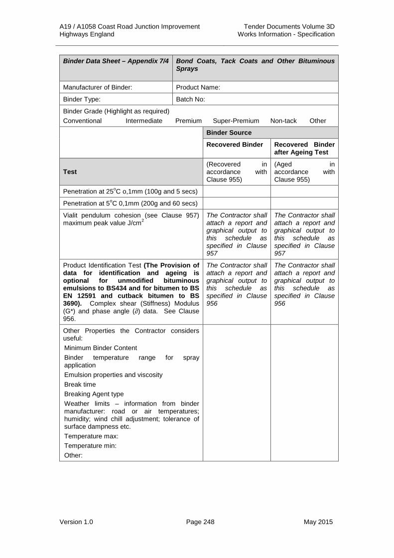
A19 / A1058 Coast Road Junction Improvement Tender Documents Volume 3D Highways England Works Information - Specification
Version 1.0 Page 248 May 2015
Binder Data Sheet – Appendix 7/4 Bond Coats, Tack Coats and Other Bituminous Sprays
Manufacturer of Binder: Product Name:
Binder Type: Batch No:
Binder Grade (Highlight as required) Conventional Intermediate Premium Super-Premium Non-tack Other
Binder Source
Recovered Binder Recovered Binder after Ageing Test
Test (Recovered in accordance with Clause 955)
(Aged in accordance with Clause 955)
Penetration at 25oC o,1mm (100g and 5 secs)
Penetration at 5oC 0,1mm (200g and 60 secs)
Vialit pendulum cohesion (see Clause 957) maximum peak value J/cm2
The Contractor shall attach a report and graphical output to this schedule as specified in Clause 957
The Contractor shall attach a report and graphical output to this schedule as specified in Clause 957
Product Identification Test (The Provision of data for identification and ageing is optional for unmodified bituminous emulsions to BS434 and for bitumen to BS EN 12591 and cutback bitumen to BS 3690). Complex shear (Stiffness) Modulus (G*) and phase angle (∂) data. See Clause 956.
The Contractor shall attach a report and graphical output to this schedule as specified in Clause 956
The Contractor shall attach a report and graphical output to this schedule as specified in Clause 956
Other Properties the Contractor considers useful: Minimum Binder Content Binder temperature range for spray application Emulsion properties and viscosity Break time Breaking Agent type Weather limits – information from binder manufacturer: road or air temperatures; humidity; wind chill adjustment; tolerance of surface dampness etc. Temperature max: Temperature min: Other:

A19 / A1058 Coast Road Junction Improvement Tender Documents Volume 3D Highways England Works Information - Specification
Version 1.0 Page 249 May 2015
APPENDIX 7/6: BREAKING UP OR PERFORATION OF EXISTING PAVEMENT
1. Any area which is required to be broken up is displayed on the pavement drawings A19T-DWG-CIV-S00-0700-0001 to 0004 inclusive.
2. “Breaking Up” shall mean the whole of the paved surface shall be broken to the complete depth of the bituminous material.
3. “Perforation” shall mean that at least 15% of the paved surface shall be broken for the complete depth of the bituminous material. Perforations shall be at least 100mm in diameter. The perforations shall be undertaken in such a way that there is at least 1 perforation in approximately every square metre of paved area.
4. Any existing pavement that is identified to be reinstated for grass-seeding of planting shall be removed for the complete bituminous depth and then broken up beneath this depth to allow for free drainage into the underlying material.

A19 / A1058 Coast Road Junction Improvement Tender Documents Volume 3D Highways England Works Information - Specification
Version 1.0 Page 250 May 2015
APPENDIX 7/9: COLD-MILLING (PLANING) OF BITUMINOUS BOUND FLEXIBLE PAVEMENT
1. Areas for Cold Milling and planing are shown on drawings A19T-DWG-CIV-S00-0700-0001 to 0004 inclusive.
2. All cold milling and planing shall be undertaken in accordance with Clause 709 of the Specification for Highway Works.
3. Any material arising from the planing operation shall be assessed for possible reuse in the Works.
4. Profile planing may be required at all pavement tie ins as defined in Appendix 7/1.
Schedule: Sweeping Areas Prior to Cold Milling
Drawing Number: Location:
A19T-DWG-CIV-S00-0700-0001 to 0004 inclusive
All pavement tie ins to existing carriageways

A19 / A1058 Coast Road Junction Improvement Tender Documents Volume 3D Highways England Works Information - Specification
Version 1.0 Page 251 May 2015
APPENDIX 7/22: REPAIRS TO POTHOLES
1. General
1.1 All loose material shall be removed before filling the hole.
1.2 All standing water shall be removed before filling the hole.
1.3 The filling material shall be compacted by a suitable means.
1.4 The surface of a compacted material shall be level with that of the adjacent road.
2. Road Stud Holes 2.1 Fill road stud socket with 6mm bituminous instant road repair material or
equivalent.
3. Holes in Paved Areas 3.1 Before any overlaying or trimming of existing surfaces is carried out, the
Contractor shall:
(i) For holes less than 0.5m2 – fill with 6mm bituminous instant road repair material or equivalent.
(ii) For holes greater than 0.5m2 – fill with 6mm nominal size dense bitumen macadam surface course.
(iii) Holes shall be backfilled with materials compacted to refusal with a circular headed vibrating hammer in layers not exceeding 75mm thick.

A19 / A1058 Coast Road Junction Improvement Tender Documents Volume 3D Highways England Works Information - Specification
Version 1.0 Page 252 May 2015
APPENDIX 11/1: KERBS FOOTWAYS AND PAVED AREAS 1. The location of kerbs, footways and other paved areas shall be shown on
the Kerbs, Footways and Paved Areas drawings (Ref: A19T-DWG-CIV-S00-1100-0001 to 0004 inclusive).
2. The Contractor shall provide precast concrete kerbs, channels, edgings and quadrants that shall comply with BS EN 1340:2003 and Clause 1101 of the Specification for Highways Works.
3. Precast concrete kerbs shall meet the following performance criteria:
Table 11/1.1: Performance Criteria of Precast Concrete Kerbs
Performance Criteria Class
(i) Resistance to freeze/ thaw with de-icing salts 3
(ii) Bending strength 2
(iii) Abrasion resistance 1
(iv) Slip resistance No requirement
4. Bedding and backing to precast concrete kerbs and edgings shall be with Type ST1 concrete. Concrete curing requirements shall comply with Clause 1027 of the Specification for Highways Works.
5. The Contractor shall provide precast concrete paving flags that shall comply with BS EN 1339:2003 and Clause 1104 of the Specification for Highways Works.
6. The bonding of flags shall comply with Clause 1104.2 of the Specification for Highways Works.
7. The Contractor shall not use the alternative bed given in Clause 1104.2 of the Specification for Highways Works for precast concrete flags less than 450 mm x 450 mm.
8. The Contractor shall refer to Appendix 7/1 of this Specification for details of the flexible surfacing materials that shall be used on footways.
9. There is no requirement for concrete / grass paving, in-situ concrete paving, precast concrete paving blocks or clay pavers in this Contract at the time of Tender.

A19 / A1058 Coast Road Junction Improvement Tender Documents Volume 3D Highways England Works Information - Specification
Version 1.0 Page 253 May 2015
APPENDIX 11/2: ACCESS STEPS 1. The location of access steps shall be shown on the Kerbs, Footways and
Paved Areas drawings (Ref: A19T-DWG-CIV-S00-1100-0001 to 0004 inclusive).
2. Access steps to feeder pillars, communication cabinets, traffic counter cabinets, ice prediction installations and the like shall comply with drawing MCX 0138 sheets 1 and 2 contained in Volume 3 of the Specification for Highways Works.
3. Access steps shall be constructed in accordance with BS 5395:2010 Part 1.
4. The Contractor shall provide and install handrails to all access steps where there is a potential risk of falling.

A19 / A1058 Coast Road Junction Improvement Tender Documents Volume 3D Highways England Works Information - Specification
Version 1.0 Page 254 May 2015
APPENDIX 12/1: TRAFFIC SIGNS: GENERAL 1. Schedule of Traffic Signs
1.1 The location of Traffic Signs to be installed as part of the Works shall be as described in the Traffic Sign Schedules (Ref: TS 001 – 088 Rev A).
1.2 The diagram number in Schedules 1, 2, 3, 4, 5 or 7 of the Traffic Signs Regulations and General Directions 2002 No. 3113 shall be as shown in the Traffic Signs Schedules.
1.3 The overall size of sign plates shall be as described in the Traffic Sign Schedules.
1.4 The requirements for type of material, preparation and finish of sign plates, posts, etc. shall be as described in the Traffic Signs Schedules.
1.5 The details of foundations including cable ducting, reinstatement and any requirements for anchorages and attachment systems including their loadings and torque settings shall be as described in the Traffic Signs Schedules.
1.6 The number, type and size of posts including details of any baseplates or flange plates shall be as described in the Traffic Sign Schedules.
1.7 The requirements for any electrical equipment compartments shall be as described in the Traffic Sign Schedules.
1.8 The type of sign face material including the Class of any retroreflective material shall be as described in the Traffic Sign Schedules.
1.9 The type of any direct illumination, whether internal or external, overhead mounted or upward pointing luminaires and whether free standing on separate foundations shall be as described in the Traffic Sign Schedules.
1.10 The luminance and impact categories of the signs and luminaires shall be as described in the Traffic Sign Schedules.
1.11 The requirements for the illumination of bollards shall be as described in the Traffic Sign Schedules.
1.12 The Contractor shall refer to Appendix 1/17 of this Specification for details of any temporary speed limit enforcement signs that shall be installed as part of the Traffic Safety and Management proposals for the scheme.
2 Sign Posts 2.1. Sign posts shall be steel hot dip galvanised to B.S. 729 at the fabrication
factory to the sizes and numbers specified on Drawing 0015/02/1200/05 and within Table 12/1/1 and be provided complete with plastic weather caps and galvanised or zinc sprayed baseplates. Baseplates are to be firmly attached to the pole by an effective means such that the protective finish of both items shall remain intact. The means of attachment shall utilise a threaded stud/bolt. Posts must incorporate a means to prevent the post from moving when planted. All steel posts are to be covered in bitumen both inside and outside the post up to a level of 150mm above ground level.
2.2. Missing butt welds are permitted in any post or RHS and only new tubes or sections may be used in the manufacture.

A19 / A1058 Coast Road Junction Improvement Tender Documents Volume 3D Highways England Works Information - Specification
Version 1.0 Page 255 May 2015
2.3 Where a sign is to be located on a single circular hollow section post then anti rotational clips are to be provided in accordance with the manufactures recommendations.
2.4 Signs requiring passive post and foundation details are identified on the sign schedules.
3 Sign Plates for Permanent Traffic Signs 3.1 All sign plates shall be constructed from 3mm (11swg) sheet aluminium.
Sign plates up to 2.4 x 1.2 metres in size shall be constructed from a single sheet of aluminium and for sign plates in excess of these dimensions the minimum number of plates shall be utilised.
3.2 Aluminium or alloy rivets shall be used to attach the frame/stiffener to the sign face to prevent failure due to differential expansion or wind pressure in accordance with BS873: Part 6; Riveting shall be uniform and spacing shall not exceed 150mm on the outside edges and 300mm elsewhere.
4 Faces for Permanent Signs 4.1 Sign fabrication drawings shall be approved by the Overseeing Organisation
prior to the manufacture of signs and shall be in accordance with BS EN 12899-1.
4.2 Sign faces shall be formed from a single piece of plastic sheeting, but, if for any reason the sign face must be fabricated from more than one piece of material, the prior approval of the Overseeing Organisation must be obtained. Joints other than vertical or horizontal will not be accepted. All joints in the sheeting shall be overlapped by not less than 6mm. No butt joints will be permitted and in horizontal joint the overlap shall be from the top. The sheeting shall be applied over the whole of the front surface of the sign to the required colours.
4.3 All plastic sheeting shall be affixed to the sign plate with pressure sensitive adhesives properly applied by vacuum applicator or pressure roller machine respectively in accordance with the sheeting manufacturer’s recommendations. Sheeting shall be provided with a manufacturer’s warranty of not less than 10 years.
4.4 Letters. Numerals, symbols, and borders shall be of types specified by the Overseeing Organisation. Cut-outs to produce legend and borders shall be of materials specified by the sheeting manufacturer. They shall be applied directly to clean, dust-free sheeting background panels and shall be applied in a manner specified by the manufacturer. Pressure sensitive adhesive coated materials shall be applied mechanically only; legend and/or borders shall be cut neatly at intersecting panel signs.
4.5 All panels, cut-out and numerals, adjacent or otherwise, adjoining sections of panels/borders, symbols/backgrounds or reflective sheeting, must be carefully matched for colour at the time of sign fabrication to provide uniform appearance both day and night. The sheeting manufacturer’s recommendations on colour matching shall be observed. Non-uniform shading or contracts between sheeting on any one sign will not be acceptable.
4.6 All edges of the applied plastic sheeting and all letters, symbols and borders shall be continuously and uniformly sealed with lacquer. Reflectorised sign plates shall additionally have a coat of clear lacquer applied to the whole of

A19 / A1058 Coast Road Junction Improvement Tender Documents Volume 3D Highways England Works Information - Specification
Version 1.0 Page 256 May 2015
the sign face at the time of fabrication of the sign. Non-reflective signs will not have an overall lacquer coat.
4.7 All surfaces shall be free of runs, drips, crazing, air bubbles, creases, scratches, dust, or other blemishes. The finish of all sign plates shall be capable of passing the testing requirements within BS EN 12899-1.
4.8 All sign plates shall be made from Class RA2 reflectorised sheeting
4.9 The back of the sign is to carry the following information:
(i) The number of the British Standard.
(ii) The name, trademark, or other means of identifying the manufacturer.
(iii) The class of retroreflective material used.
(iv) The month and year of manufacture.
4.10 The Contractor shall provide and affix to each sign a label showing the sign reference number (as supplied by the Overseeing Organisation) in 75mm high black characters on a white reflectorised background. The characters shall be arranged vertically. The label shall be located on the rear of the sign plate with the lower edge 50mm above the lower edge of the sign. Before the label is affixed the rear of the sign plate shall be cleaned and primed. After fixing the label shall be sealed. Materials and methods of fixing shall be in accordance with the manufacturer’s instructions.
5 Construction and Assembly of Permanent Traffic Signs 5.1 Holes shall not be drilled into sign faces for the different attachment of clips
or luminaire brackets. Signs with a major dimension of less than 600mm will require two aluminium fixing channels to be attached by means of aluminium rivets to accept the fixing bolts and clips.
5.2 Circular signs shall be stiffened where the diameter is 600mm or more, triangular signs where the width of the base is 600mm or more. All other signs shall be stiffened where either the vertical or horizontal dimension is 600mm or over unless specifically schedules as unframed. The stiffening structure shall be as detailed in BS EN 12899-1.
5.3 Additional stiffeners shall be provided to conform to the rigidity requirements set out in BS EN 12899-1. Al stiffeners shall be secured to the sign faces with aluminium rivets.
5.4 All brackets, clips, purlins, frames and stiffeners used in sign assemblies shall be manufactured from stainless steel, or extruded aluminium alloy section rail, cast aluminium or mild steel. Saddles shall be aluminium alloy or other material approved by the Overseeing Organisation and shall be provided with a nylon strip or other approved insulating material.
5.5 All screws, nuts, bolts, and washers shall be stainless steel but where these are in contact with the faces which may be damaged by over-tightening, protective washers of nylon or other approved material shall be used.
5.6 Where purlins are required they shall be of tubular steel 8swg and 47.5mm outside diameter and have their ends sealed. Purlins shall be attached to each vertical member of the sign frame and the distance at the top and bottom purlins from the parallel sign edges shall not exceed 450mm.

A19 / A1058 Coast Road Junction Improvement Tender Documents Volume 3D Highways England Works Information - Specification
Version 1.0 Page 257 May 2015
Intermediate purlins shall be spaced equally apart at centres not exceeding 1.5 metres. A connection shall be made at every point where a purlin crosses a post.
5.7 Where purlins are used, the sign stiffening and framing shall be continuous in the vertical direction. Where no purlins are used, the sign stiffening and framing shall be continuous in the horizontal direction.
5.8 A nylon strip or similar approved insulating material shall be fixed between the purlin and aluminium framing.
6 Site Work 6.1 The location of all signs shall be agreed with the Overseeing Organisation
prior to any work taking place.
6.2 Temporary covering of signs shall accord with the Contractor’s temporary traffic management layout and with the prior approval of the Overseeing Organisation
6.3 The temporary covering for signs shall be in accordance with the Manufacturers recommendation.
6.4 Each sign shall be clearly identified with location reference to marks, in accordance with the works order, on the lower left hand corner of the rear of the sign, on 75mm high black letters/numbers on a yellow background and with a referencing system agreed by the Overseeing Organisation.
6.5 Where two or more posts are used for signs over footways, supports shall give a minimum horizontal clearance of 1.5m between posts and positioned so as to minimise disruption to pedestrian movements. Assembles not located in footways shall use the quarter points of the sign plate to position the posts.
6.6 The minimum clearance between kerb face and sign edge shall be 450 mm on roads with speed limits of 40 mph or less and 1.2 m on roads over 40 mph. This clearance will normally be specified and refers to the lowest part of the sign assembly excluding any vertical supports. The following minimum height clearances to the underside of signs shall be maintained:-
• Over highways – min 5.500 m
• Over footways – min 2.150 m
• Over cycleways – min 2.500 m
• Over grass verges – between 0.90 m and 1.5 m or over 2.15 m
7 Illumination of Traffic Signs 7.1 The illuminated traffic signs are depicted on road lighting drawings. For all
‘electrical work’ reference should be made to Series 1400. Illuminated traffic signs whether externally or internally lit shall be designed in accordance with BS EN 12899; 1 2007.
7.2 The traffic signs where specified shall be lit by external overhead mounted luminaires with an impact category of 1. The lighting manufacturer will provide details of the lantern levels and appropriate luminance levels. The method of switching is to be via a contactor in a feeder pillar.
7.3 The method of switching the illumination is by the use of a PECU set to switch at 55 lux.

A19 / A1058 Coast Road Junction Improvement Tender Documents Volume 3D Highways England Works Information - Specification
Version 1.0 Page 258 May 2015
7.4 Bollards are to be internally illuminated.
7.5 Accommodation for electrical equipment shall be of three types
• An integral post and housing and integral structural steels shall comply with the requirements of BS In addition structural steel hot rolled hollow sections shall comply with the requirements of BS 4 part 2. If manufactured from tubular steel or circular section, circumferential joints shall be of the sleeve type and restricted to points where the post is designed with reduced diameters. The external transition of the sleeve joint shall be continuously welded and dressed to present a smooth profile.
• A separate housing for posts up to 115mm diameter provided with a sockets to accept the sign post in the top of the housing. The socket shall be provided with a sealing ring and stainless steel socket headed screws to secure the post.
• For larger poles and rectangular hollow sections a detachable housing is required and this to be bolted on to the post or RHS by stainless steel screws and shall project 150mm below ground level. Bushed mating holes of 25mm internal diameter lean cut and free from burrs and sharp edges are to be provided for the electrical connection to the sign.
7.6 The three types of housing shall be constructed of steel or other approved material and shall comply with the following requirements.
7.7 All housings shall be fully weatherproof and shall be fitted with a hard wood or marine ply backboard at least 12mm thick with a minimum dimension of 500mm x 130mm. The backboard shall be capable of being removed and replaced. The door aperture shall not be less than these dimensions and a close fitting overlapping or other door is required with a weatherstrip fitted onto the housing above the door. Doors shall be interchangeable between housings without adaptation and shall prevent the ingress of water. The door shall be fitted with an approved pattern non-corrodible tamperproof lock with a triangular recessed operating boss. Keys are to be provided with a first consignment of housings at the rate of 10% of the total number of housings. A clearance of not less than 100mm is required to be maintained between the backboard and all parts of the door. The bottom of the door opening shall be at least 75mm above ground level. A single purpose earth terminal shall be provided in a readily accessible position at the side of the opening and shall comprise a bass screw, 2 no brass tab washers and a plain brass washer and nut. Cable slots and door openings shall be in the same place, be accurately cut and be smooth, and free from irregularities and burrs. The housings shall contain a slot to accommodate the electricity service cables, 150mm below ground level and shall be finished free of burrs.
8. Additional Information 8.1 Temporary covering of signs shall accord with the Contractor's Traffic Safety
and Management proposals and with the prior approval of the Project Manager.
8.2 The temporary covering for signs shall be in accordance with the Manufacturers recommendation.
8.3 Sign fabrication drawings shall not be required for standard warning and regulatory signs.

A19 / A1058 Coast Road Junction Improvement Tender Documents Volume 3D Highways England Works Information - Specification
Version 1.0 Page 259 May 2015
8.4 Three keys shall be provided to the Project Manager for any such locks to traffic sign housings.
8.5 The Contractor shall provide a label showing the sign reference number (as supplied by the Project Manager) in 75 mm high black characters on a white reflectorised background. The characters shall be arranged vertically on the label which shall be located on the rear of the sign plate with the lower edge 50 mm above the lower edge of the sign. Before the label is affixed the rear of the sign plate shall be cleaned and primed. After fixing the label shall be sealed. Materials and methods of fixing shall be in accordance with the manufacturer’s instructions.
8.6 The Contractor shall comply with the requirements of sub-Clause 1208.4 of the Specification for Highways Works with regards the filling of pockets in concrete foundations.

A19 / A1058 Coast Road Junction Improvement Tender Documents Volume 3D Highways England Works Information - Specification
Version 1.0 Page 260 May 2015
APPENDIX 12/2: TRAFFIC SIGNS: MARKER POSTS 1.1 There are no marker posts included in the Works at the time of Tender.

A19 / A1058 Coast Road Junction Improvement Tender Documents Volume 3D Highways England Works Information - Specification
Version 1.0 Page 261 May 2015
APPENDIX 12/3: TRAFFIC SIGNS: ROAD MARKINGS AND STUDS 1.1 The location, colour and material type for permanent road markings shall be
as shown on the Road Marking Layout drawings (Ref: A19T-DWG-CIV-S00-1200-0006).
1.2 Permanent road markings shall comply with Tables 12/3.1 and 12/3.2 and the following standards:
(i) BS EN 1436:2007 Road Marking Materials – Road Marking Performance for Road Users.
(ii) BS EN 1871:2000 Road Marking Materials – Physical Properties.
(iii) BS EN 1423:1998 Road Marking Materials – Drop on Materials – Glass Beads, Anti-skid Aggregates and Mixtures of the Two.
(iv) BS EN 1424:1997 Road Marking Materials – Premix Glass Beads
Table 12/3.1: Road Marking Material Requirements
Property BS EN 1436 Reference
Requirement Value
Colour Table 6 White TBC
Luminance Factor Table 2 Class B3 0.4
Skid Resistance Table 7 Class S3 55
Retro reflectivity Table 3, Classes of RL for dry markings
Class R2 100
Table 12/3.1: Retroreflectivity Requirements
Property BS EN 1436 Reference
Requirement Value
Retroreflectivity Table 4, Classes of RL for road markings during wetness
Class RW3 >=50
Retroreflectivity Table 5, Classes of RL for road markings during rain
Class RR3 >=50
1.3 Unless otherwise stated, road markings shall not be laid more than 6mm thick.
1.4 The length and width of the road markings shall be as shown on the Road Marking Layout drawings and shall be in accordance with the Traffic Signs Regulations and General Directions 2002 with a permitted tolerance as shown in Table 12/3.3 below.
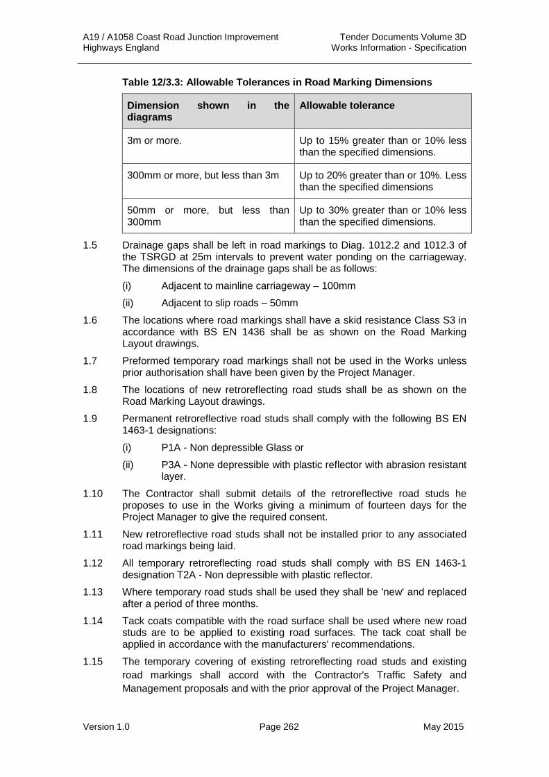
A19 / A1058 Coast Road Junction Improvement Tender Documents Volume 3D Highways England Works Information - Specification
Version 1.0 Page 262 May 2015
Table 12/3.3: Allowable Tolerances in Road Marking Dimensions
Dimension shown in the diagrams
Allowable tolerance
3m or more. Up to 15% greater than or 10% less than the specified dimensions.
300mm or more, but less than 3m Up to 20% greater than or 10%. Less than the specified dimensions
50mm or more, but less than 300mm
Up to 30% greater than or 10% less than the specified dimensions.
1.5 Drainage gaps shall be left in road markings to Diag. 1012.2 and 1012.3 of the TSRGD at 25m intervals to prevent water ponding on the carriageway. The dimensions of the drainage gaps shall be as follows:
(i) Adjacent to mainline carriageway – 100mm
(ii) Adjacent to slip roads – 50mm
1.6 The locations where road markings shall have a skid resistance Class S3 in accordance with BS EN 1436 shall be as shown on the Road Marking Layout drawings.
1.7 Preformed temporary road markings shall not be used in the Works unless prior authorisation shall have been given by the Project Manager.
1.8 The locations of new retroreflecting road studs shall be as shown on the Road Marking Layout drawings.
1.9 Permanent retroreflective road studs shall comply with the following BS EN 1463-1 designations:
(i) P1A - Non depressible Glass or
(ii) P3A - None depressible with plastic reflector with abrasion resistant layer.
1.10 The Contractor shall submit details of the retroreflective road studs he proposes to use in the Works giving a minimum of fourteen days for the Project Manager to give the required consent.
1.11 New retroreflective road studs shall not be installed prior to any associated road markings being laid.
1.12 All temporary retroreflecting road studs shall comply with BS EN 1463-1 designation T2A - Non depressible with plastic reflector.
1.13 Where temporary road studs shall be used they shall be 'new' and replaced after a period of three months.
1.14 Tack coats compatible with the road surface shall be used where new road studs are to be applied to existing road surfaces. The tack coat shall be applied in accordance with the manufacturers' recommendations.
1.15 The temporary covering of existing retroreflecting road studs and existing road markings shall accord with the Contractor's Traffic Safety and Management proposals and with the prior approval of the Project Manager.

A19 / A1058 Coast Road Junction Improvement Tender Documents Volume 3D Highways England Works Information - Specification
Version 1.0 Page 263 May 2015
1.16 Removal of existing road markings and road studs shall be carried out without damage to the road surface.
1.17 The locations where enhanced night time visibility of retroreflecting road markings shall be required shall be as shown on the Road Marking Layout drawings.
1.18 The spacing of transverse raised ribs on edge lines to Diag. 1012.2 and 1012.3 of the TSRGD shall be as noted on the Road Marking Layout drawings.

A19 / A1058 Coast Road Junction Improvement Tender Documents Volume 3D Highways England Works Information - Specification
Version 1.0 Page 264 May 2015
APPENDIX 12/4: TRAFFIC SIGNS: CONES, CYLINDERS, FTDS AND OTHER TRAFFIC DELINEATORS
1.1 There are no cones, cylinders, FTD’s or other traffic delineators included in the Works at the time of Tender.

A19 / A1058 Coast Road Junction Improvement Tender Documents Volume 3D Highways England Works Information - Specification
Version 1.0 Page 265 May 2015
APPENDIX 12/5: TRAFFIC SIGNS: TRAFFIC SIGNALS 3. Permanent Traffic Signals
Location 3.1 The Contractor shall execute and complete traffic signal heads and
controller, ducting, connection to an electricity supply, traffic detection loops including control units, signal posts and gantries, cables, inspection chambers, road markings and the like at the locations shown on the Traffic Signal Layout drawing (Ref: A19T-DWG-CIV-S00-1200-0006).
3.2 All signal equipment shall be installed such that it has a minimum clearance of 450 mm from the edge of the carriageway.
Equipment 3.3 The Contractor shall provide the following equipment including any ancillary
items required for the installation of the traffic signals. The number and quantity shall be as shown on the Traffic Signal Layout drawings. (i) Vehicular signal heads.
(ii) Pedestrian signal heads.
(iii) Signal heads for cyclists.
(iv) Combined push button display units and tactile indicators.
(v) 600mm x 600mm duct chambers.
(vi) 600mm x 450mm duct chambers.
(vii) Passively Safe 4m 140mm diameter traffic signal poles (NAL Sockets).
(viii) Siemens ST900 Traffic Signal Controllers Gemini unit, GSM modem and MOVA licence.
(ix) Remote Cabinet.
(x) Controller configuration.
(xi) Wireless detector studs.
(xii) Repeater units.
(xiii) Access Points.
(xiv) 16 core 1.5mm2 armoured traffic signal cable.
(xv) Traffic signal ducting.
3.4 Where a particular type of equipment is specified in the Contract, the Contractor shall only use that type of equipment, unless an alternative is approved in writing by the Project Manager.
3.5 The Contractor shall supply and affix self-adhesive numbers / phase letters following the erection of each / head / pole / cabinet. The application of self-adhesive numbers to such street furniture shall have a 10 year life and have yellow numbers on a black background with a 75 mm ‘X’ height. These numbers shall be visible on the approach to the installation.
3.6 The label details for the controllers shall be referenced as follows:
Controller Number 1 (xxx)* The Highways England TechMAC maintenance contractor shall provide this information.

A19 / A1058 Coast Road Junction Improvement Tender Documents Volume 3D Highways England Works Information - Specification
Version 1.0 Page 266 May 2015
3.7 The pole numbers shall be affixed 2.0m above ground level, under the lower bracket of the signal head signal head bracket in accordance with the following instructions:-
(i) If a pole contains a PRIMARY signal head, then the number shall face in the same direction as that head.
(ii) If a pole contains SECONDARY signal heads and no Primary head then the number shall face in the direction of any one of the heads.
Operation 3.8 The configuration and installation of the traffic signal controller shall be the
responsibility of the Contractor.
3.9 The traffic signal controller shall be connected to the Highways England Area 14 remote monitoring system. Remote monitoring configurations and live update diagrams shall be supplied to the Project Manager by the Contractor. The MOVA set up and validation will be undertaken by the Project Manager.
3.10 Traffic signal controllers shall operate in accordance with the TR2500A controller Works specifications issued with the scheme drawings, and any variations to these instructed by the Project Manager.
3.11 The MOVA unit shall have the ability to support and shall be configured for the following:
(i) Detector counting.
(ii) Flow & Occupancy logging.
(iii) End of saturation flag outputs.
3.12 Two copies of the controller Works specification and build sheets shall be provided to the Project Manager.
3.13 The controller configuration and configurations for all equipment where appropriate shall be provided as a computer file in an electronic format acceptable to the Project Manager.
3.14 Manuals shall be provided in both electronic and hard copy format for equipment purchased unless otherwise directed by the Project Manager.
3.15 Two 13A maintenance sockets to BS1363:4:1995 shall be provided as a minimum on all controllers and remote cabinets. All ancillary equipment shall be wired into its own Miniature Circuit Breaker (MCB) on the power distribution rail and not into the maintenance sockets.
3.16 A detector channel or input identification card shall be provided by the signals contractor with the controller. This card shall identify every detector input with the loop designation within the TR2500 A Works specification controller build sheets and as shown on the scheme drawing. This shall be encapsulated in plastic and adhered to the inside of the controller door.
3.17 The manual panel is to be clearly marked with the use of an additional weatherproof diagram / label firmly attached indicating button number and stage called for ease of manual control.
3.18 The contractor shall ensure that all cable arrangements comply with BS7671:2008.

A19 / A1058 Coast Road Junction Improvement Tender Documents Volume 3D Highways England Works Information - Specification
Version 1.0 Page 267 May 2015
3.19 All cables shall be clearly and permanently labelled. ELV cables shall be labelled with a yellow tag clearly showing the pole number.
3.20 A telecommunications carrier interface shall not be provided as part of the Works at the time of Tender.
3.21 Inspection chambers shall be located close enough to the required pole locations to allow dot plugs and disconnection systems to be connected correctly.
Detection 3.22 The type of detector (loop or above ground), location, configuration, size,
shape and other facilities will be as shown on the Traffic Signal Layout drawing.
3.23 The Contractor shall comply with the requirements of the Highways England MOVA installation guidelines (Ref: MCH 1542 Rev C).
3.24 Detector packs shall be powered from a 24V supply within the controller case.
3.25 All cables shall be clearly and permanently labelled in the controller and in chambers. Detector cables shall be labelled with a white tag clearly showing the detector number.
Testing 3.26 The Factory Acceptance Tests (FAT) shall be conducted either at the
manufacturers, suppliers or installers depot close to the Site location. The controller shall be fully configured and assembled prior to the FAT. The Contractor shall provide all necessary test equipment in a suitable environment set aside for the purpose. The Contractor shall provide a competent person for any technical discussion or changes required resulting from or associated with the tests and to sign the FAT sheet containing any agreed actions to complete the test. Additional tests may be required at the discretion of the Project Manager.
3.27 The Project Manager will normally expect to carry out the FAT on the actual controller hardware and equipment being supplied (e.g. Gemini unit set up for MOVA and remote monitoring) and in the event of this not being practical for any reason then agreement must be reached prior to other arrangements being made.
3.28 The remote monitoring configurations shall be supplied seven days in advance of the FAT to allow the configuration to be loaded onto the in-station and the remote monitoring tested as part of the FAT.
3.29 All equipment installed on Site shall be subject to a Site Acceptance Test (SAT) carried out in the presence of the Project Manager.
3.30 The Contractor shall provide fourteen days’ notice to the Project Manager for any such SAT and it shall only take place if the pre-commissioning and all applicable test sheets are provided to the Project Manager by 15:00 hours on the day prior to the proposed test.
3.31 The Contractor shall provide the Project Manager with a completion certificate to confirm the installation complies with BS 7671:2008.
3.32 A shelter shall be provided on Site by the Contractor to protect the sensitive electronic equipment from the effects of inclement weather when installing, testing, or commissioning.
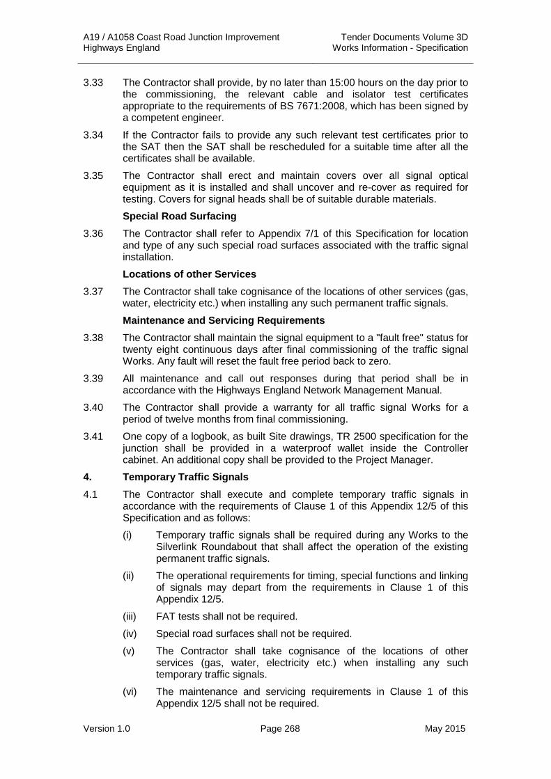
A19 / A1058 Coast Road Junction Improvement Tender Documents Volume 3D Highways England Works Information - Specification
Version 1.0 Page 268 May 2015
3.33 The Contractor shall provide, by no later than 15:00 hours on the day prior to the commissioning, the relevant cable and isolator test certificates appropriate to the requirements of BS 7671:2008, which has been signed by a competent engineer.
3.34 If the Contractor fails to provide any such relevant test certificates prior to the SAT then the SAT shall be rescheduled for a suitable time after all the certificates shall be available.
3.35 The Contractor shall erect and maintain covers over all signal optical equipment as it is installed and shall uncover and re-cover as required for testing. Covers for signal heads shall be of suitable durable materials.
Special Road Surfacing 3.36 The Contractor shall refer to Appendix 7/1 of this Specification for location
and type of any such special road surfaces associated with the traffic signal installation.
Locations of other Services 3.37 The Contractor shall take cognisance of the locations of other services (gas,
water, electricity etc.) when installing any such permanent traffic signals.
Maintenance and Servicing Requirements 3.38 The Contractor shall maintain the signal equipment to a "fault free" status for
twenty eight continuous days after final commissioning of the traffic signal Works. Any fault will reset the fault free period back to zero.
3.39 All maintenance and call out responses during that period shall be in accordance with the Highways England Network Management Manual.
3.40 The Contractor shall provide a warranty for all traffic signal Works for a period of twelve months from final commissioning.
3.41 One copy of a logbook, as built Site drawings, TR 2500 specification for the junction shall be provided in a waterproof wallet inside the Controller cabinet. An additional copy shall be provided to the Project Manager.
4. Temporary Traffic Signals 4.1 The Contractor shall execute and complete temporary traffic signals in
accordance with the requirements of Clause 1 of this Appendix 12/5 of this Specification and as follows:
(i) Temporary traffic signals shall be required during any Works to the Silverlink Roundabout that shall affect the operation of the existing permanent traffic signals.
(ii) The operational requirements for timing, special functions and linking of signals may depart from the requirements in Clause 1 of this Appendix 12/5.
(iii) FAT tests shall not be required.
(iv) Special road surfaces shall not be required.
(v) The Contractor shall take cognisance of the locations of other services (gas, water, electricity etc.) when installing any such temporary traffic signals.
(vi) The maintenance and servicing requirements in Clause 1 of this Appendix 12/5 shall not be required.

A19 / A1058 Coast Road Junction Improvement Tender Documents Volume 3D Highways England Works Information - Specification
Version 1.0 Page 269 May 2015
4.2 The Contractor shall design any temporary traffic signal installation and shall submit his proposals to the Project Manager for acceptance prior to any such Works on Site. This shall include the temporary re-location of permanent traffic signals and the associated cabling arrangements.
4.3 Authorisation of the proposed temporary traffic signals will be required from the Project Manager before the temporary traffic signals shall be made operational.
4.4 The contractor shall test any temporary traffic signals to ensure they operate as agreed.
4.5 Temporary traffic signals may be powered by a portable generator.
4.6 The Contractor shall only use Highways England approved cross carriageway cable protection measures. Where possible the cabling for the temporary traffic signals shall use the permanent traffic signal ducting.
5. Controlled Crossings 5.1 Controlled crossings shall not be required as part of the Works at the time of
Tender.
6. Zebra Crossings 6.1 Zebra crossings shall not be required as part of the Works at the time of
Tender.
7. Remote Monitoring Outstation Requirements 7.1 The Contractor shall provide an Outstation Monitoring and Control Unit
(OMCU) that shall be capable of monitoring the operation of the control equipment and reporting to the in-station any faults that are detected.
7.2 Unless otherwise instructed by the Project Manager, the outstation shall be compatible with a Siemens Remote Monitoring in-station and shall have the latest version of firmware issue installed at the time of commissioning.
7.3 The OMCU shall be able to detect and report the following fault conditions:
(i) LED signal lamp failures indicating lamp colour and phase.
(ii) Signals off and be able to distinguish between:
a. Mains power failure.
b. Controller fault.
c. Power failure to signal aspects.
d. Signal lamps switched off at manual panel.
(iii) Timing violations of the following periods:
a. Minimum green period.
b. Intergreen period.
c. Maximum green period.
d. All red period.
(iv) Signals stuck in phase/stage.
(v) Detector faults.
(vi) Dim / Bright failures.

A19 / A1058 Coast Road Junction Improvement Tender Documents Volume 3D Highways England Works Information - Specification
Version 1.0 Page 270 May 2015
(vii) Loss of MOVA/UTC control.
(viii) Controller modes and mode changes.
7.4 The OMCU shall be able to monitor the operation of the signal controller to ensure that the correct cyclic sequence is followed and report any violations to the in-station as faults.
7.5 All detectors shall be monitored by the OMCU for each installation.
7.6 The OMCU shall be provided and installed with standby batteries to enable a mains power failure to be reported within one minute of any such failure occurring.
7.7 The Contractor shall be responsible for altering / amending Remote Monitoring Unit configuration on Site and for supplying the Area 14 TechMAC in-station with a live update diagram.

A19 / A1058 Coast Road Junction Improvement Tender Documents Volume 3D Highways England Works Information - Specification
Version 1.0 Page 271 May 2015
APPENDIX 12/6: TRAFFIC SIGNS: SPECIAL SIGN REQUIREMENTS ON GANTRIES
1.1 There are no special sign requirements on gantries included in the Works at the time of Tender.

A19 / A1058 Coast Road Junction Improvement Tender Documents Volume 3D Highways England Works Information - Specification
Version 1.0 Page 272 May 2015
APPENDIX 13/1: INFORMATION TO BE PROVIDED WHEN SPECIFYING LIGHTING COLUMNS AND BRACKETS
1. General 1.1 The Contractor shall provide lighting columns that shall have internally
positioned, opposite each door, a non-hygroscopic baseboard not less than 15mm thick and of a suitable size to accept the appropriate cut-out and control equipment. The baseboard shall be fixed to the inside of the column by means of purpose made welded brackets.
1.2 Columns shall be provided with a weatherproof single door, which shall be free from irregularities and burrs. Each door shall be fitted with a stainless steel tamper proof locking device as indicated in HCD drawing no. K1.
1.3 The number of door keys to be supplied shall be 10% of the number of columns erected subject to a minimum of six keys.
2. Design of Lighting Column Foundations 2.1 The Contractor shall establish the soil types on Site and submit, to the
Project Manager for acceptance, lighting column foundation details appropriate to the conditions found.
2.2 The Contractor shall design foundations for the planted lighting columns detailed on the Contract drawings. The design calculations and supporting information shall be submitted to the Project Manager not less than seven days’ before he intends to install any lighting columns.
3. Data Sheets 3.1 The Contractor shall within one month of the commencement of the Works
and prior to placement of any orders for materials, supply the Project Manager, for his approval, triplicate copies of completed Appendix 13/2 Data sheets for each type of lighting column.
4. Identification and Location Markings 4.1 Location markers for inspection and maintenance purposes shall be
provided on the columns after erection as follows:
(i) Columns mounted in the central reserve shall have 75 mm high numbering on both sides of the column; each number facing oncoming traffic at an angle of approximately 45o.
(ii) Verge mounted columns shall have 75 mm high numbering on one side of the column facing oncoming traffic.
4.2 The Contractor shall agree column numbering with the Project Manager prior to the commencement of Works.
5. Handling, Transport and Erection 5.1 Where practical all lighting columns shall be installed such that the location
of the door is facing away from oncoming traffic.
6. Amendments and Additions to BS 5649:1978 (AMD 3136, 1979) 6.1 All lighting columns shall have a cable entry slot width ‘X’ of 75mm.

A19 / A1058 Coast Road Junction Improvement Tender Documents Volume 3D Highways England Works Information - Specification
Version 1.0 Page 273 May 2015
TABLE 13/1.1: Lighting Column and Bracket Information
Number of Columns
Nominal Column Height
Bracket Details Column Details Location Factor Contractor to Complete Manufacturer Catalogue nos.
Type Proj. Arm Angle
Column Material & Type
Protec-tion
Base Type
No. of Door Openings
Door Size Doors to be Fixed
Cable Entry Details
Terrain Cat.
Exposure Coeff.
Topo Factor (f)
Reference Wind Velocity Speed
(m/s)
2 no. 5m Single, Post-Top
N/A N/A Galvanised Steel, Raise & Lower (Mid Hinged)
Refer to Note 1
Planted 1 Refer to Note 1
N/A Below Door III 1,63 1 24
4 no. 5m Single, Post-Top
N/A N/A Galvanised Steel Refer to Note 1
Planted 1 Refer to Note 1
N/A Below Door III 1,63 1 24
4 no. 8m Single, Post-Top
N/A N/A Galvanised Steel Refer to Note 1
Planted 1 Refer to Note 1
N/A Below Door II 2,21 1 24
18 no. 12m Single 0.5m 0 Galvanised Steel Refer to Note 1
Planted 1 Refer to Note 1
N/A Below Door II 2,47 1 24
7 no. 12m Single 0.5m 0 Galvanised Steel Refer to Note 1
Flange Plate
1 Refer to Note 1
N/A Below Door II 2,47 1 24
44 no. 12m Single, Post-Top
N/A N/A Aluminium,
Passively Safe,
100:HE:1
NA, Refer to Note 1
Planted 1 Refer to Note 1
N/A Below Door II 2,47 1 24
4 no. 12m Single, Post-Top
N/A N/A Galvanised Steel NA, Refer to Note 1
Planted 1 Refer to Note 1
N/A Below Door II 2,47 1 24
10 no. 12m Single 0.5m 0 Galvanised Steel Refer to Note 1
Planted 1 Refer to Note 1
N/A Below Door II 2,47 1 24
22 no. 10m Double 1.0m 0 Galvanised Steel Refer to Note 1
Flange Plate
1 Refer to Note 1
N/A Below Door II 2,35 1 24

A19 / A1058 Coast Road Junction Improvement Tender Documents Volume 3D Highways England Works Information - Specification
Version 1.0 Page 274 May 2015
5 no. 12m Double 1.0m 0 Galvanised Steel Refer to Note 1
Flange Plate
1 Refer to Note 1
N/A Below Door II 2,47 1 24
NOTES:
1. Road lighting columns shall be in accordance with the Highways England / Aone+ (Area 14) specification.

A19 / A1058 Coast Road Junction Improvement Tender Documents Volume 3D Highways England Works Information - Specification
Version 1.0 Page 275 May 2015
Table 13/1.2: Luminaire Information
Number of Luminaires
Luminaire Details Contractor to Complete Manufacturer Catalogue nos.
Luminaire Luminaire Angle
Weight (kg)
Projected Surface by Side (m2)
4 no. Proposed 100W High Pressure Sodium
0 11.0 0.15
4 no. Proposed 16klm LED luminaire 0 15.5 0.067
69 no. Proposed 26klm LED luminaire 0 20.5 0.079
36 no. Proposed 29klm LED luminaire 0 20.5 0.079
10 no. Proposed 36klm LED luminaire 0 20.5 0.079
22 no. Proposed 43klm LED luminaire 0 20.5 0.079
NOTES: 1. Refer to Table 14/4.1 for proposed luminaire and lamp details. 2. Weight and projected side surface are based on typical luminaires.

A19 / A1058 Coast Road Junction Improvement Tender Documents Volume 3D Highways England Works Information - Specification
Version 1.0 Page 276 May 2015
APPENDIX 13/2: (SPECIFICATION FOR HIGHWAY WORKS) TYPICAL LIGHTING COLUMN AND BRACKET DATA - SHEET 1

A19 / A1058 Coast Road Junction Improvement Tender Documents Volume 3D Highways England Works Information - Specification
Version 1.0 Page 277 May 2015
APPENDIX 13/2: (SPECIFICATION FOR HIGHWAY WORKS) TYPICAL LIGHTING COLUMN AND BRACKET DATA - SHEET 2

A19 / A1058 Coast Road Junction Improvement Tender Documents Volume 3D Highways England Works Information - Specification
Version 1.0 Page 278 May 2015
APPENDIX 13/3: INSTRUCTIONS FOR COMPLETION OF LIGHTING COLUMN AND BRACKET DATA SHEETS
1. General 1.1 When information is not required a dash shall be inserted in the appropriate
boxes.
1.2 Where a Data Sheet is amended it shall be given a new revision number with a date.
1.3 The revision numbers shall be consecutive letters of the alphabet, commencing with “A”.
1.4 The date of the revision shall agree with the date of the Contractor’s signature.
1.5 The column, or bracket material shall be steel, aluminium, reinforced or prestressed concrete, glass fibre reinforced plastic or any other approved material.
1.6 The material design strength shall be the minimum specified in the design. Where more than one material is used values for all materials shall be given.
1.7 All relevant entries shall be made on the Data Sheet before the document is certified by the Contractor.
2. Column Data 2.1 The column nominal height shall be selected from clause 2 or 3 of BS 5649-
2: 1978 as appropriate.
2.2 The number of door openings shall agree with the manufacturer’s drawing.
2.3 The cross-section of the base compartment shall be indicated by a dimensioned diagram / sketch.
2.4 The acceptable positions of bracket arms relative to the door position shall be indicated on the diagram. Where all positions are acceptable the box noted “ANY” shall be ticked.
2.5 Where concrete is necessary around the planted base in accordance with sub-Clauses 1305.3 and 1305.4 the minimum diameter shall be entered.
2.6 For flange bases all forces and moments used in the design of the foundations, anchorages and attachment systems shall be given.
2.7 The corrosion protection system used on the column when new shall be recorded. Where additional steel is provided for sacrificial purposes the amount shall be recorded.
2.8 The signs and attachments surface area, eccentricity from the centre line of the column to the centre of area of the sign and height above ground level to the centre of area of the sign shall be stated.
3. Bracket Data 3.1 The luminaire lever arms, weight and maximum windage area quoted shall
be based on the most adverse loading on the bracket when it is attached to any of the columns quoted in the compatible column sections.
(Note: The luminaire lever arms are the horizontal distances from the centre of gravity of the luminaire and, if applicable, the centroid of the windage surface area to the end of the bracket joint).

A19 / A1058 Coast Road Junction Improvement Tender Documents Volume 3D Highways England Works Information - Specification
Version 1.0 Page 279 May 2015
APPENDIX 13/4: INFORMATION TO BE PROVIDED WHEN SPECIFYING CCTV MASTS
1. The location, number and requirements for CCTV masts shall be shown on the Motorway Communications layout plans (Ref: A19T-DWG-CIV-S00-1500-0001 to 0004 Inclusive).
2. The Contractor shall complete the Data Sheets and submit them to the Project Manager prior to any such Works commencing.

A19 / A1058 Coast Road Junction Improvement Tender Documents Volume 3D Highways England Works Information - Specification
Version 1.0 Page 280 May 2015
APPENDIX 13/5: (SPECIFICATION FOR HIGHWAY WORKS) TYPICAL CCTV MAST DATA

A19 / A1058 Coast Road Junction Improvement Tender Documents Volume 3D Highways England Works Information - Specification
Version 1.0 Page 281 May 2015
APPENDIX 13/6: INSTRUCTIONS FOR COMPLETION OF CCTV MAST DATA SHEETS
1. General 1.1 When information is not required a dash shall be inserted in the appropriate
boxes.
1.2 Where a Data Sheet is amended it shall be given a new revision number with a date.
1.3 The revision numbers shall be consecutive letters of the alphabet, commencing with “A”.
1.4 The date of the revision shall agree with the date of the Contractor’s signature.
1.5 The mast shall be steel.
1.6 The material design strength shall be the minimum specified in the design. Where more than one material is used values for all materials shall be given.
1.7 All relevant entries shall be made on the Data Sheet before the document is certified by the Contractor.
2. Mast Data 2.1 The mast nominal height shall be as defined in BD 83 (DMRB 2.2.12),
clause as appropriate.
2.2 The number of door openings shall agree with the manufacturer’s drawing.
2.3 The cross-section of the base compartment shall be indicated by a dimensioned diagram/sketch.
2.4 The acceptable positions of the mounting relative to the door position shall be indicated on the diagram. Where all positions are acceptable the box noted “ANY” shall be ticked.
2.5 For flange bases all forces and moments used in the design of the foundations, anchorages and attachment systems shall be given.
2.6 The corrosion protection system used on the column when new shall be recorded. Where additional steel is provided for sacrificial purposes the amount shall be recorded.
2.7 The signs and attachments surface area, eccentricity from the centre line of the mast to the centre of area of the sign and height above ground level to the centre of area of the sign shall be stated.
3. Equipment Data 3.1 The lever arms, weight and maximum windage area quoted for the CCTV
camera with associated mountings and housings shall be based on the most adverse loading when it is attached to any of the masts quoted in the compatible mast sections.
(Note: The lever arms are the horizontal distances from the centre of gravity of the CCTV camera with associated mounting and housing and, if applicable, the centroid of the windage surface area to the centreline of the mast.)

A19 / A1058 Coast Road Junction Improvement Tender Documents Volume 3D Highways England Works Information - Specification
Version 1.0 Page 282 May 2015
APPENDIX 13/8: (SPECIFICATION FOR HIGHWAY WORKS) TYPICAL CANTILEVER MAST DATA - SHEET 1

A19 / A1058 Coast Road Junction Improvement Tender Documents Volume 3D Highways England Works Information - Specification
Version 1.0 Page 283 May 2015
APPENDIX 13/8: (SPECIFICATION FOR HIGHWAY WORKS) TYPICAL CANTILEVER MAST DATA - SHEET 2

A19 / A1058 Coast Road Junction Improvement Tender Documents Volume 3D Highways England Works Information - Specification
Version 1.0 Page 284 May 2015
APPENDIX 13/9: INSTRUCTIONS FOR COMPLETION OF CANTILEVER MASTS DATA SHEETS
1. General 1.1 When information is not required a dash shall be inserted in the appropriate
boxes.
1.2 Where a Data Sheet is amended it shall be given a new revision number with a date.
1.3 The revision numbers shall be consecutive letters of the alphabet, commencing with “A”.
1.4 The date of the revision shall agree with the date of the Contractor’s signature.
1.5 The material design strength shall be the minimum specified in the design.
1.6 All relevant entries shall be made on the Data Sheet before the document is certified by the Contractor.
2. Cantilever Mast Data 2.1 The cantilever mast nominal height shall be selected from clause 2 or 3 of
BS 5649-2: 1978 (AMD 3136, 1979) as appropriate.
2.2 The number of door openings shall agree with the manufacturer’s drawing.
2.3 The cross-section of the base compartment shall be indicated by a dimensioned diagram/sketch.
2.4 The acceptable positions of the outreach arms relative to the door position shall be indicated on the diagram. Where all positions are acceptable the box noted “ANY” shall be ticked.
2.5 Where concrete is necessary around the planted base in accordance with sub-Clauses 1305.3 and 1305.4 the minimum diameter shall be entered.
2.6 For flange bases all forces and moments used in the design of the foundations, anchorages and attachment systems shall be given.
2.7 The corrosion protection system used on the cantilever mast when new shall be recorded. Where additional steel is provided for sacrificial purposes the amount shall be recorded.
2.8 The signs and attachments surface area, eccentricity from the centre line of the cantilever mast to the centre of area of the sign and height above ground level to the centre of area of the sign shall be stated.
3. Equipment Data 3.1 The lever arms, weight and maximum windage area quoted for the traffic
signal or speed camera with associated mountings and housings shall be based on the most adverse loading when it is attached to any of the masts quoted in the compatible mast sections.
(Note: The lever arms are the horizontal distances from the centre of gravity of the traffic signal or speed camera with associated mounting and housing and, if applicable, the centroid of the windage surface area to the centreline of the mast.)

A19 / A1058 Coast Road Junction Improvement Tender Documents Volume 3D Highways England Works Information - Specification
Version 1.0 Page 285 May 2015
APPENDIX 14/1: SITE RECORDS 1. As Built Information 1.1 As built drawings shall be produced by the Contractor. Copies of the
Contract drawings will be provided by the Project Manager in AutoCAD format and paper format. The record drawings produced by the Contractor shall be produced on AutoCAD and stored on DVD/R and provided to the Project Manager.
1.2 The information shall include:
(i) Maintenance or operating manuals for installed equipment.
(ii) Cable records shall be determined from kerb lines or fence lines.
(iii) A schematic distribution layout drawing indicating the distribution arrangement of each private cable network.
(iv) Test certificates in accordance with BS 7671.
(v) A schedule of abandoned cables.
(vi) Cable offsets taken at 20m intervals where cables maintain a steady line, and at 5m intervals where the line of the cable varies.

A19 / A1058 Coast Road Junction Improvement Tender Documents Volume 3D Highways England Works Information - Specification
Version 1.0 Page 286 May 2015
APPENDIX 14/2: LOCATION OF LIGHTING UNITS AND FEEDER PILLARS
1. General 1.1 All information relating to the existing installations possessed by the Project
Manager regarding the position of existing underground cabling, feeder pillars and lighting unit positions will be made available to the Contractor without any guarantee as to its accuracy
2. Location of Lighting Units and Feeder Pillars 2.1 The location of all lighting units shall be as detailed on the Contract
drawings.
2.2 The minimum lighting requirements for this scheme are detailed in Table 14/2.1 on the following page.
2.3 If an alternative luminaire is proposed by the Contractor the following information shall be issued to the Project Manager for approval prior to the commencement of Works to demonstrate compliance with the requirements of Table 14/2.1, based on the equipment proposed therein:
(i) Road and area (where applicable) lighting design calculations and explanatory notes demonstrating compliance with the requirements of Table 14/2.1.
(ii) The information issued shall include luminaire type / catalogue no., lamp type / design lumen output, and show the calculated lighting levels.

A19 / A1058 Coast Road Junction Improvement Tender Documents Volume 3D Highways England Works Information - Specification
Version 1.0 Page 287 May 2015
Table 14/2.1: Lighting Level Requirements
Location Compliance With Maintenance Factor
Road Surface Category
Nominal Road Width
Luminaire Overhang
Contractors Proposed Luminaire
A19 Main Carriageway and Slip Roads BS5489-1: 2013 Lighting Class M2 0.74 C2 / 0.07 N/A N/A
A19/A1058 Roundabout BS5489-1: 2013 Lighting Class C2 0.74 C2 / 0.07 N/A N/A
NOTES: 1. Road lighting class stated in Table A14/2/1 for all HA maintained roads have been provisionally agreed with Area 14.

A19 / A1058 Coast Road Junction Improvement Tender Documents Volume 3D Highways England Works Information - Specification
Version 1.0 Page 288 May 2015
APPENDIX 14/3: TEMPORARY LIGHTING 1. Temporary Lighting 1.1 Existing road lighting units, lit sign units and associated power supplies shall
be maintained until the new installation has been commissioned.
1.2 The Contractor shall ensure that the requirement for temporary lighting and associated power supplies is identified and appraised fully during preparation of the programme of Works defined in Appendix 1/13.
1.3 The Contractor shall design and install temporary LV power supply networks for all locations where the existing cable network is removed before / during installation of the permanent road lighting Works.
1.4 All temporary LV power supply networks designed by the Contractor shall comply fully with the requirements of BS 7671. The Contractors proposals shall be submitted to the Project Manager for acceptance seven days before installation.
1.5 All temporary lighting shall comply fully with the requirements of BS 5489. The Contractors proposals shall be submitted to the Project Manager for acceptance seven days before installation.
1.6 Temporary lighting shall not be removed or switched off until:
(i) The permanent installation is in full operation.
(ii) An inspection has been carried out on the operation of the permanent installation not less than twenty four hours or more than seven days after commissioning.
(iii) Any adjustments, remedial or replacement Works found necessary have been carried out and the system re-inspected as (ii) above.

A19 / A1058 Coast Road Junction Improvement Tender Documents Volume 3D Highways England Works Information - Specification
Version 1.0 Page 289 May 2015
APPENDIX 14/4: ELECTRICAL EQUIPMENT FOR ROAD LIGHTING 1. Luminaires 1.1 All luminaires shall have a fuse holder adjacent to the terminal block with a
cartridge fuse protecting each set of control gear.
1.2 All luminaires shall be as detailed on the Contract drawings.
1.3 All luminaires for road lighting shall have a degree of protection rating IP66 to BS EN 60529 for luminaire optical system and IP66 to BS 60529 for luminaire control gear.
1.4 The Contractor shall insert in Table 14/4.1 details of all the proposed luminaires.
2. Photo-Electric Control Units (PECU’s) 2.1 Photo-Electric Control Units (PECU’s) to be used are detailed in Table
14/4.4.
2.2 The Contractor shall insert in Table 14/4.4, details of all Photo-Electric Control Units (PECU’s) proposed to be used.
2.3 Circuits to be group switched have been identified on the Contract drawings.
3. Ballasts 3.1 Luminaire control gear shall be an electronic dimmable driver.
4. Cut-outs, Fuse Holders, Fuses and Miniature Circuit Breakers (MCB’s) 4.1 All fuses within lighting columns, signs and bollards shall be HRC type,
complying with the requirements of BS 88-2. Fuse ratings shall be in accordance with the Contract drawings and / or the manufacturer’s recommendations.
4.2 The Contractor shall insert in Table 14/4.2 details of all the cut-outs proposed to be used.
4.3 The Contractor shall determine the short circuit rating, through consultation with the Distribution Network Operator (DNO) if necessary, of all miniature circuit breakers.
4.4 Live terminals including the neutral shall be isolated on removing the fuse carrier.
4.5 Interlocking shall ensure that the fuse carrier cannot be inserted or withdrawn under load conditions.
4.6 A clear “OFF” indication shall be provided when the unit has been isolated and a locking off facility shall be provided in the OFF position only.
4.7 The design of the cut-out shall be such that it is possible to incorporate facilities, integral within the unit, for the termination of an additional Local Authority outgoing fused circuit.
4.8 Terminals shall be sufficient to allow the termination of conductors with a CSA of up to 25mm2.
4.9 The design of the cut-out shall be such that there is no possibility of contact with live parts during electrical testing.

A19 / A1058 Coast Road Junction Improvement Tender Documents Volume 3D Highways England Works Information - Specification
Version 1.0 Page 290 May 2015
4.10 All passively safe road lighting columns shall incorporate a NAL SIS (similar or approved) passively safe disconnection system in accordance with BS EN 12767: 2007. The system shall comprise of a NAL SIS Solo / Duo (Pillar) monitor unit (similar or approved) mounted in the road lighting feeder pillar and a NAL SIS impact sensor (similar or approved) mounted within the road lighting column, connected via a sensor signal cable.
4.11 All passively safe illuminated traffic signs shall incorporate an IP67 rated snatch plug and socket passively safe disconnection system in accordance with BS EN 12767: 2007.
5. Base Compartment Fixing Arrangements 5.1 All electrical equipment installed within the base compartment of lighting
columns shall be generally arranged as detailed on the Contract drawings.
6. Feeder Pillars 6.1 Feeder pillars shall be manufactured out of cast iron, galvanised sheet steel
and shall be fitted with hinged, lockable door.
6.2 A diagram identifying the circuits shall be fixed to the inside of each feeder pillar door and shall be protected by a clear weatherproof cover.
6.3 Feeder pillars shall be provided with a brass earth stud, which shall be bonded to the main earthing terminal.
6.4 Feeder pillars shall be provided with weatherproof doors, which shall be free from irregularities and burrs. Each door shall be fitted with a stainless steel tamper proof locking device as indicated in HCD drawing no. K1 and contain a hasp and staple.
6.5 All feeder pillars shall be in accordance with the Contract drawings.
7. Wiring 7.1 All wiring and installation of components within lighting columns and lit sign
units shall be in accordance with the Contract drawings.
8. Earthing 8.1 All earthing for lighting columns shall be carried out in accordance with the
Contract drawings and BS 7671.
8.2 The main earth terminal block to which the terminals of all equipment shall be separately bonded shall be connected to the incoming supply earth by the main earthing conductor.
8.3 The main earthing conductor shall be of copper and be in accordance with the following Table:
Table 14/4.5: Earth Conductor Details
C.S.A. of Phase Conductor (S) (mm2)
Min. C.S.A. of Corresponding Main Earthing Conductor (Sp) (mm2)
6 10 16 25
6 10 16 16

A19 / A1058 Coast Road Junction Improvement Tender Documents Volume 3D Highways England Works Information - Specification
Version 1.0 Page 291 May 2015
8.4 Bonding conductors shall be of 6 mm2 stranded copper, with the exception of the bonding conductor to the door, which shall be 16 mm2 flexible copper.
8.5 Where the cross sectional area of the incoming phase conductor is greater than 35 mm2, the Project Manager shall be consulted regarding the size of the main earthing and bonding.
9. Underground and Ducted Cable 9.1 The route for underground cable trenches shall be as detailed on the
Contract drawings.
9.2 Cables shall be laid in accordance with the requirements of the Contract drawings. Additional protection shall be provided to cables where detailed on the Contract drawings.
9.3 The Contractor shall insert in Table 14/4.3 the details of all road lighting cables proposed to be used.
9.4 When cable termination does not proceed immediately following installation of the cable and the cable ends are buried, their positions shall be marked with a permanent marker block as described in Clause 1421.11. The block shall be marked as instructed by the Project Manager.
10. Cable Joints 10.1 Cable joints shall not be permitted unless shown otherwise on the Contract
drawings.
10.2 Where cable joints are detailed on the Contract drawings. Cable joint marker blocks are not required to be placed over each cable joint.
11. Armoured Cable Terminations 11.1 Armoured cable terminations shall be carried out in accordance with the
Contract drawings.
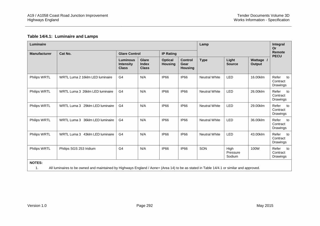
A19 / A1058 Coast Road Junction Improvement Tender Documents Volume 3D Highways England Works Information - Specification
Version 1.0 Page 292 May 2015
Table 14/4.1: Luminaire and Lamps
Luminaire Lamp Integral Or Remote PECU
Manufacturer Cat No. Glare Control IP Rating
Luminous Intensity Class
Glare Index Class
Optical Housing
Control Gear Housing
Type Light Source
Wattage / Output
Philips WRTL WRTL Luma 2 16klm LED luminaire G4 N/A IP66 IP66 Neutral White LED 16.00klm Refer to Contract Drawings
Philips WRTL WRTL Luma 3 26klm LED luminaire G4 N/A IP66 IP66 Neutral White LED 26.00klm Refer to Contract Drawings
Philips WRTL WRTL Luma 3 29klm LED luminaire G4 N/A IP66 IP66 Neutral White LED 29.00klm Refer to Contract Drawings
Philips WRTL WRTL Luma 3 36klm LED luminaire G4 N/A IP66 IP66 Neutral White LED 36.00klm Refer to Contract Drawings
Philips WRTL WRTL Luma 3 43klm LED luminaire G4 N/A IP66 IP66 Neutral White LED 43.00klm Refer to Contract Drawings
Philips WRTL Philips SGS 253 Iridium G4 N/A IP66 IP66 SON High Pressure Sodium
100W Refer to Contract Drawings
NOTES: 1. All luminaires to be owned and maintained by Highways England / Aone+ (Area 14) to be as stated in Table 14/4.1 or similar and approved.

A19 / A1058 Coast Road Junction Improvement Tender Documents Volume 3D Highways England Works Information - Specification
Version 1.0 Page 293 May 2015
Table 14/4.2: Lighting Unit Terminations
Termination Type Contractor To Complete
Manufacturer Cat No.
T1
T2
T3
T4
T5
NOTES: 1. Completed data sheets shall be provided as soon as the Contract has been
awarded. 2. Details of the road lighting columns are given on Table A13/1/1.
Table 14/4.3: Cables
Cable Type Contractor To Complete
Manufacturer Cat No.
6 mm2 3 core XLPE/PVC/SWA/PVC Cu.
16 mm2 3 core XLPE/PVC/SWA/PVC Cu.
25 mm2 3 core XLPE/PVC/SWA/PVC Cu.
NOTES: 1. Completed data sheets shall be provided as soon as the Contract has been
awarded. 2. All cables shall be B.A.S.E.C. approved.
Table 14/4.4: Photo-Electric Control Units (PECU’s)
Description Switch On/ Off Ratio
Number Of Parts
Contractor To Complete
Manufacturer Model/ Cat No.
Group controlled PECU located on FP1 and FP2.
1:0.5 negative (55 lux/28 lux)
NOTES: 1. Completed Data Sheets shall be provided as soon as the Contract has been
awarded.

A19 / A1058 Coast Road Junction Improvement Tender Documents Volume 3D Highways England Works Information - Specification
Version 1.0 Page 294 May 2015
APPENDIX 14/5: ELECTRICAL EQUIPMENT FOR TRAFFIC SIGNS 1. Base Compartment Fixing Arrangements 1.1 All electrical equipment installed within the base compartment of traffic signs
shall be generally arranged as detailed on the Contract drawings.
2. Wiring 2.1 All wiring and installation of components within lighting columns and lit sign
units shall be in accordance with the Contract drawings.

A19 / A1058 Coast Road Junction Improvement Tender Documents Volume 3D Highways England Works Information - Specification
Version 1.0 Page 295 May 2015
APPENDIX 15/1: MOTORWAY COMMUNICATIONS 1. General 1.1 This appendix 15/1 specification details the requirements and
responsibilities required for the completion of the Works on the A19/A1058 Coast Road Junction Scheme. Where requirements differ, it is split into sub headings for the Highways England and the Tyne Tunnel works.
1.2 Specific Tyne Tunnel Works are as detailed on the Motorway Communication drawings (Ref: A19T-DWG-CIV-1500-0001 to 0004 inclusive).
1.3 The Contractor shall install all items of the Works identified and detailed within the Issued Schedule within the Appendices.
1.4 The Contractor shall be responsible for the supply and delivery of the ITS system that has not been listed as Project Manager Issued Equipment items.
1.5 Works required to support the technology systems in accordance with scheme drawings and Contract Documentation are listed below:
(i) Testing of existing longitudinal and Transverse Ducts for suitable re-use.
(ii) Hard standing and foundations installations for equipment 600 cabinets and power 609 cabinets.
(iii) Installation of equipment 600 Cabinets.
(iv) Installation of power 609 Cabinets.
(v) Access steps and handrails (where identified) at all location Sites.
(vi) Installation of Cantilever post for use of Lane Control Units, Variable Message Sign and fixed CCTV.
(vii) Installation of CCTV masts for the use of PTZ cameras.
(viii) Installation of a full longitudinal and local ducted network for Tyne Tunnel.
(ix) Installation of a full longitudinal and local ducted network for Highways England to NRTS Standard.
1.6 The Contractor shall supply, deliver, install and test a ducted communications system to provide an integrated duct network to support the operation for Tyne Tunnel Company’s infrastructure. The communications infrastructure shall be suitable to support the operation of:
(i) Cantilever mounted Lane Control Units;
(ii) Cantilever mounted Variable Message Signs;
(iii) Cantilever mounted Closed Circuit Television (CCTV);
(iv) Connectivity to the Tyne Tunnel system;
1.7 The Contractor shall undertake all Works associated with the installation of cables, cabinets, message signs, lane control units, CCTV and ancillary items in accordance with the scheme specific drawings.

A19 / A1058 Coast Road Junction Improvement Tender Documents Volume 3D Highways England Works Information - Specification
Version 1.0 Page 296 May 2015
1.8 The Contractor shall be responsible for the installation and commissioning of the following technology systems:
(i) Installation and Commissioning of CCTV cameras and electronic equipment.
(ii) Installation and Commissioning of Lane Control Units and equipment on cantilever posts.
(iii) Installation and Commissioning of Variable Message Sign and equipment on cantilever posts (including any associated Roadside Controller and Power Distributor).
1.9 Commissioning of the whole ITS system shall be carried out in accordance with the Contract Documentation and the Tyne Tunnel Specification in the Contract Documentation.
1.10 The Contractor shall programme the Works through close liaison with the Project Manager and Tyne Tunnel Company’s Management. The Contractor shall be aware of other contractors undertaking work on Site adjacent to and overlapping the Site extents for this scheme. To ensure the smooth, safe and practical running of traffic management and ‘system’ interfaces between these Sites, such that disruption to traffic and operational systems shall be minimised.
2. General Requirements 2.1 The Contractor shall comply with Clause 1502 of the Specification for
Highways Works and be responsible for ensuring and controlling the suitable storage of all Project Manager Issued Equipment, both within the Site compound and at other agreed storage areas.
2.2 Electronic equipment shall be stored in a dry heated area.
2.3 A comprehensive list of Site by Site equipment requirements can be found in the Contract Documentation.
2.4 The Contractor is required to install all cabling for the scheme. A comprehensive list of quantities and cable type can be found in the communications and power cable schedules.
2.5 The Contractor is required to provide all method statements to the Project Manager for approval prior to the commencement of any Works.
2.6 The Contractor may be required to provide all cabling and detailed electronic equipment for the scheme. A comprehensive list of quantities and cable type can be found in the Contract Documentation.
Tyne Tunnel 2.7 The Contractor shall ensure that mains power is connected (in accordance
with the Manufacturers’ recommendations) to all Lane Control Units and Variable Message Signs once in the Contractors possession.
3. Materials Equipment and Workmanship 3.1 The Contractor shall comply with Clause 1503 of the Specification for
Highways Works.
3.2 All surplus material and waste shall be disposed of in accordance with the Contractors Site Waste Management Plan.

A19 / A1058 Coast Road Junction Improvement Tender Documents Volume 3D Highways England Works Information - Specification
Version 1.0 Page 297 May 2015
3.3 All workmanship shall be of a high standard, to ensure reliability of systems and ease of future maintenance.
3.4 A comprehensive list of the requirements can be found in the Contract Documentation.
4. Site Records 4.1 Accurate drawings shall comply with Clause 1504 of the Specification for
Highways Works and shall be produced using the completed Site record drawings as a basis.
4.2 Test certification and associated record information shall be produced on an ongoing basis and submitted at periods of no greater than seven days. Test certificates shall be supplied and cross-referenced to the apparatus identified on the record drawings.
4.3 Detailed Site records shall be provided throughout the duration of the Works and made available at all times for review.
4.4 The Contractor shall decommission all redundant cables and equipment that shall have been identified in the Contract Documentation and during the course of the Works.
4.5 All drawings shall be produced in accordance with the Contract Documentation.
4.6 The Contractor shall provide accurate information to the Project Manager for the completion of the Maintenance Handover package to Highways England and the Tyne Tunnel Company.
5. Provision of Message Signs, Indicators, Cabinets, Cables and Ancillary Items Highways England
5.1 The Contractor shall Comply with Clause 1505 of the Specification for Highways Works and be responsible for the supply of all items of cable and ancillary equipment not supplied as Project Manager Issued Equipment.
5.2 The Contractor shall assist in the updating of the equipment schedule. All items shall be deemed to be accepted unless reported in writing to the Project Manager within seven days of delivery or collection.
5.3 The Contractor shall be responsible for the security of all items of cable and equipment from the time collected until hand over, or return of redundant / surplus equipment to the Project Managers stores. The Contractor shall replace any item of Project Manager Issued Equipment damaged or lost whilst in the Contractor’s care.
5.4 A comprehensive list of the requirements can be found in the Contract Documentation.
Tyne Tunnel 5.5 The Contractor may be responsible for the supply of all items of cable,
electronic equipment and ancillary equipment. Unless supplied by the Project Manager and as identified as part of the detailed design.
5.6 A comprehensive list of the requirements can be found in the Tyne Tunnel Specification in the Contract Documentation.

A19 / A1058 Coast Road Junction Improvement Tender Documents Volume 3D Highways England Works Information - Specification
Version 1.0 Page 298 May 2015
6. Cables Highways England
6.1 Communications cable, provided by the Contractor, shall be in accordance with the Contract Documentation.
6.2 Power cables for the communications system, provided by the Contractor, shall be in accordance with:
(i) Armoured energy cables, three core XLPE/SWA/PVC to BS 5467.
(ii) Power cables will be sized in accordance with BS 7671.
(iii) Highways England Specification TR2583.
6.3 The Contractor shall be responsible for the safe disposal of all cable drums in accordance with the Site Waste Management Plan.
Tyne Tunnel 6.4 The Contractor shall provide power and communication cables in
accordance with the Tyne Tunnel Specification in the Contract Documentation.
6.5 The Contractor shall be responsible for the safe disposal of all cable drums in accordance with the Site Waste Management Plan.
7. Cable Installation Highways England
7.1 The Contractor shall comply with Clause 1507 and:
(i) Install all cables in accordance with the scheme specific drawings.
(ii) Pull cables through ducts into appropriate cabinets.
(iii) Terminate all cables to equipment mounted in cabinets.
(iv) Test all power cable installations to BS 7671.
(v) Test all communications cable installations carried out by the Contractor.
7.2 The Contractor shall be responsible for the installation of all power cables from the Distribution Network Operator Interface cabinet to the associated power supply within a 609 Cabinet. This design shall include all temporary Works and enabling works.
7.3 All communications equipment shall be sited within the highways boundary. The nominal routing of ducts and cables and the approximate locations of cabinets and chambers are shown on the scheme drawings. The detailed routing shall be agreed on Site, the Contractor taking due cognisance of the locations for chambers and the constraints imposed in the Construction Environmental Management Plan. The exact locations of infrastructure equipment shall be agreed with the Project Manager on Site.
7.4 Communications cables shall not be installed in longitudinal or transverse power ducts. See Appendix 15/2 for further information.
7.5 Cables shall be installed in a manner ensuring that no undue physical stresses are applied before, during, or following cable installation.

A19 / A1058 Coast Road Junction Improvement Tender Documents Volume 3D Highways England Works Information - Specification
Version 1.0 Page 299 May 2015
7.6 Should any damage occur to any cable, however slight, it shall be brought to the attention of the Project Manager immediately and confirmed in writing. The method to be used for rectifying the damage shall be agreed with the Project Manager who will confirm if a cable repair is acceptable.
Tyne Tunnel 7.7 The Contractor shall:
(i) Install all cables in accordance with the scheme specific drawings.
(ii) Pull cables through ducts into appropriate cabinets.
(iii) Terminate all cables to equipment wherever mounted and other Tyne Tunnel assets.
(iv) Test all power cable installations to BS 7671.
(v) Test all communications cable installations carried out by the Contractor.
7.8 The Contractor shall be responsible for the installation of all power cables from the Tyne Tunnel Central Administration Building to the associated power supply within a 609 Cabinet. This design shall include all temporary Works and enabling works.
7.9 All communications equipment shall be sited within the Tyne Tunnels boundary. The nominal routing of ducts and cables and the approximate locations of cabinets and chambers are shown on the scheme drawings. The detailed routing shall be agreed on Site with the Project Manager taking due cognisance of the locations for chambers and the constraints imposed in the Construction Environmental Management Plan. The exact locations of infrastructure equipment shall be agreed with the Project Manager on Site.
7.10 Cables shall be installed in a manner ensuring that no undue physical stresses are applied before, during, or following cable installation.
7.11 Should any damage occur to any cable, however slight, it shall be brought to the attention of the Project Manager immediately and confirmed in writing. The method to be used for rectifying the damage shall be agreed with the Project Manager who will confirm if a cable repair is acceptable.
8. Installation of Cabinets 8.1 The Contractor shall install cabinets to comply with Clause 1508 of the
Specification for Highways Works and at locations as shown in the scheme specific drawings.
8.2 The 600 cabinet is a multi-purpose cabinet that can house all necessary equipment as well as provide communication and power to all internal drivers and equipment. Power to the cantilever post shall be isolated from the 609 cabinet or gantry cabinet.
8.3 Hard standings, access paths, steps and handrails shall be installed at appropriate Sites within the design to ensure that access/egress to working areas permit maintenance activities to be carried out safely. The Contractor shall ensure that the final system allows for safe maintenance by the Maintenance Contractor, as required by the Construction (Design and Management) Regulations 2014.
8.4 When sighting cabinets and identifying duct routes, care shall be taken to minimise damage to existing planting.

A19 / A1058 Coast Road Junction Improvement Tender Documents Volume 3D Highways England Works Information - Specification
Version 1.0 Page 300 May 2015
8.5 The Contractor shall provide safe access from maintenance access points to all new cabinet Sites at ground level in accordance with the Highway Construction Detail drawings. Safe access shall be formed by means of access pathways, and steps and handrail as required. Slopes exceeding 1 in 3 shall be provided with steps and handrail and ditch crossings shall be provided as necessary. Maintenance access locations can be identified within the scheme drawings.
8.6 Equipment 600 Cabinets will be installed in accordance with Clause 1508 of the Specification for Highways Works.
8.7 Equipment 600 and 609 Cabinet foundations, Plinth and Frame 610 will be installed in accordance with Clause 1508 of the Specification for Highways Works.
8.8 Cabinet foundations for locations at ground level shall be determined by the ground conditions and topography results. Cabinet foundation locations shall be agreed with the Project Manager.
8.9 Wherever possible the earth surrounding cabinet foundations shall be re-graded as an alternative to providing retaining structures to ensure that the earthworks will not migrate, or collapse, due to subsequent effects of weather or slope stability. The need for retaining structures or extent of re-grading, as applicable, shall be agreed with the Project Manager. Retaining structures shall be provided to support earthworks to include the entire length of the suite of cabinets and to provide a minimum level of hardstanding area.
8.10 The Contractor shall ensure that there is safe access, typically with a minimum of 700 mm clearance to the rear of cabinet Sites with the doors open to allow for access.
8.11 The immediate areas surrounding the hardstanding at the new cabinet Site, and any joints between slabs forming the hardstanding, shall be treated to eliminate and prohibit the growth of weeds, in a manner agreed with the Project Manager.
8.12 The Contractor shall install the appropriate equipment and drivers complete with polycarbonate enclosure(s) as per scheme schematic drawings.
8.13 Plinth 610 foundations shall be installed in advance of cabinet installation. Foundation size for Cabinets 600 and 609 shall be 900 mm x 900 mm x 310 mm deep. Where foundations are cast in-situ they shall be allowed to cure for the duration as required by the manufacturer before the cabinet is erected. Foundations cast in-situ shall be adequately protected during the curing period and shall be given a Class U2 finish.
9. Gantries for Lane Control Units 9.1 The Contractor shall comply with Clause 1509 of the Specification for
Highways Works and install Cantilever mounted signalling equipment to support the operation of Lane Control Units, CCTV and Variable Message Signs.
9.2 At each new gantry Site identified on the scheme drawings, the Contractor shall:
(i) Install the appropriate 600 and 609 cabinets in accordance to scheme specific drawings.

A19 / A1058 Coast Road Junction Improvement Tender Documents Volume 3D Highways England Works Information - Specification
Version 1.0 Page 301 May 2015
(ii) Install equipment to form a Gantry control Site in accordance with the Tyne Tunnel Specification in the Contract Documentation.
9.3 It is the Contractor’s responsibility for the installation and commissioning of the Lane Control Units, CCTV and Variable Message Signs as shown in the scheme drawings.
10. Marker Tape 10.1 The marker tape shall be installed for ducts as per Clause 1511 of the
Specification for Highways Works.
11. Installation of Ancillary Items Highways England
11.1 The Contractor shall comply with Clause 1512 of the Specification for Highways Works and at each cabinet Site the incoming cables to cabinets shall be installed and terminated by the Contractor. The Contractor shall:
(i) In each 609 cabinet, terminate the incoming 3-core power cable to the protection devices and install cable reduction joints where applicable;
(ii) In each 600 cabinet, ensure that incoming cabling has sufficient room to bend and are not installed in a compromising position;
(iii) In each 609 cabinet, terminate all outgoing cables;
(iv) Install all local power and communications cables in 600 cabinets and equipment at each cabinet Site and terminate cables; and
(v) The Contractor shall test all power supply installations at cabinet Sites to BS 7671.
11.2 The nominal location of cable joints are shown on the scheme drawings. The exact locations shall be subject to the cable routes agreed with the Project Manager.
11.3 Any further sub-contractor proposed by the Contractor shall be able to demonstrate that they are conversant with the specific item of equipment they are to install and that the operatives are experienced in the installation and testing of such plant.
11.4 The Contractor shall install and terminate all cables in accordance with the Standards.
Tyne Tunnel 11.5 At each Cantilever Gantry Site detailed on the scheme drawings, the
Contractor shall:
(i) Install an appropriate Gantry Distribution Unit (GDU) and terminate incoming cable.
(ii) Terminate outgoing communications cables to gantry equipment.
(iii) Install an appropriate Gantry Power Distribution Unit.
(iv) Terminate outgoing 3-core power cables to the gantry equipment.

A19 / A1058 Coast Road Junction Improvement Tender Documents Volume 3D Highways England Works Information - Specification
Version 1.0 Page 302 May 2015
11.6 Incoming cables to cabinets shall be installed and terminated by the Contractor. The Contractor shall:
(i) In each 609 cabinet, terminate the incoming 3-core power cable to the protection devices and install cable reduction joints where applicable.
(ii) In each 600 cabinet, ensure that incoming cabling has sufficient room to bend and are not installed in a compromising position.
(iii) In each 609 cabinet, terminate all outgoing cables.
(iv) Install all local power and communications cables in 600 cabinets and equipment at each cabinet Site and terminate cables.
(v) The Contractor shall test all power supply installations at cabinet Sites to BS 7671.
11.7 The nominal location of cable joints are shown on the scheme drawings. The exact locations shall be subject to the cable routes agreed with the Project Manager.
11.8 Any further sub-contractor proposed by the Contractor shall be able to demonstrate that they are conversant with the specific item of equipment they are to install and that the operatives are experienced in the installation and testing of such plant.
11.9 The Contractor shall install and terminate all cables in accordance with the Standards.
12. Jointing and Termination of Multi-pair Communications Cables 12.1 Testing and terminating of the communications cables shall only be carried
out by suitably experienced personnel.
12.2 The Contractor shall install and terminate cables in 600 cabinets at locations detailed on the scheme drawings.
12.3 The requirements can be found in the Tyne Tunnel Specification in the Contract Documentation.
13. Cable Connectors 13.1 Cable connectors shall be as described within the Tyne Tunnel Specification
in the Contract Documentation and be of a suitable industry standard for the cable type and intended use.
14. Termination and Jointing of Power Supply Cables for Communications 14.1 The Contractor shall comply with Clause 1516 of the Specification for
Highways Works.
14.2 The 600 cabinets shall always be visible from the associated item of equipment it supplies power to. The 600 cabinets shall be safely and easily accessible from the equipment Site. With the exception of the electricity interface cabinets the distance between any 600 cabinet and the equipment that it supplies shall not exceed 30 m.
14.3 The maximum cable Cross Sectional Area that can satisfactorily be accommodated in a 609 cabinet is 25 mm². Where larger power cables are required, the Contractor shall provide and install a cable reduction joint where appropriate.

A19 / A1058 Coast Road Junction Improvement Tender Documents Volume 3D Highways England Works Information - Specification
Version 1.0 Page 303 May 2015
15. Earthing & Bonding 15.1 Earthing and bonding shall comply with the requirements of BS 7671 and BS
7430.
15.2 Any installations that are found not to meet with the requirements of BS 7671 shall be brought to the attention of the Project Manager and no further work will be undertaken at that Site until instruction is received from the Project Manager.
16. Cable Testing 16.1 Cable Testing shall comply with Clause 1518 of the Specification for
Highways Works and be in accordance with the requirements of the Contract Documentation.
16.2 The Contractor shall conduct Level 2 tests on each individual installed cable length.
16.3 The Contractor shall carry out Stage 1, Stage 2 and Level 2 tests on each individual section of power cable installed under this contract.
16.4 The Contractor shall be responsible for the approval of all witnessed test results.
17. Labelling and Numbering 17.1 Labels shall comply with Clause 1519 of the Specification for Highways
Works and be provided and installed on all new equipment and cables as per Contract Documentation. A schedule of labels shall be submitted to the Project Manager for approval prior to fabrication/installation.
17.2 Typical labels for electrical supply, distribution and other electrical supply cabinets can be viewed in MCX0145 & MCX0171.
17.3 The Contractor shall provide, supply and install all labels at each signal Site. This shall include but not be limited to:
(i) Gantry post address labels;
(ii) Equipment type and designation labels;
(iii) Power supply warning flashes; and
(iv) Other warning labels.
17.4 The Contractor shall provide, supply and install all cabinet labels. This shall include but not be limited to:
(i) Cabinet address labels;
(ii) Equipment type and designation labels;
(iii) Power supply warning flashes;
(iv) Fibre optic warning flashes;
(v) Circuit diagrams; and
(vi) Other warning labels.
18. Loading 18.1 No loading is required in this contract at the time of Tender.

A19 / A1058 Coast Road Junction Improvement Tender Documents Volume 3D Highways England Works Information - Specification
Version 1.0 Page 304 May 2015
19. Removal and Re-siting of Existing Equipment 19.1 The Contractor shall comply with Clause 1521 of the Specification for
Highways Works.
19.2 The Contractor shall be required to remove the redundant existing equipment identified on the scheme specific drawings and the schedule in the Contract Documentation. Equipment will be identified to show if being returned to the Project Manager or for disposal.
19.3 No equipment shall be removed or cables disconnected or cut until approved by the Project Manager.
19.4 The Contractor shall be responsible for the safe disposal of all redundant equipment according to the Contractor’s disposal management plan.
20. Motorwarn System 20.1 There is no requirement for a Motorwarn System in this contract at the time
of Tender.
21. Trial Pits 21.1 Trial pits shall be excavated by the Contractor to determine the location of
underground equipment. The use of mechanical digging methods shall be limited.
22. Maintaining the Existing Communications Network 22.1 The Contractor shall comply with Clause 1525 of the Specification for
Highways Works.
22.2 The Contractor shall be aware that the maintenance of the existing communications network is the sole responsibility of the appointed Highways England or Tyne Tunnel Company maintenance contractor.
23. The Inspection and Testing of Electrical Installations 23.1 The inspection and testing of electrical installations shall comply with Clause
1526 of the Specification for Highways Works and the requirements of the Contract Documentation.
24. Cable Installation at Transmission Stations 24.1 The Contractor may be required to install or terminate cables within the Tyne
Tunnel Central Administration Building.
25. Modifications to Existing Cabinets Highways England
25.1 The Contractor shall comply with Clause 1528 of the Specification for Highways Works and any modifications to existing cabinets must be in accordance with the either the Specification for Highways Works or the Tyne Tunnel Specification as appropriate.
26. Temporary Emergency Telephones 26.1 There is no requirement for temporary emergency telephones in this
contract at the time of Tender.
27. Cable Ducts 27.1 Refer to Appendix 15/2.

A19 / A1058 Coast Road Junction Improvement Tender Documents Volume 3D Highways England Works Information - Specification
Version 1.0 Page 305 May 2015
28. Chambers for Motorway Communication Cables 28.1 Refer to Appendix 15/2.
29. Proving and Testing of Ducts 29.1 Refer to Appendix 15/2.
30. Closed Circuit Television 30.1 Closed Circuit Television (CCTV) will be installed in accordance with the
requirements of the Contract Documentation.
30.2 The Contractor shall install a CCTV System with associated cabling at each location identified on the scheme drawings.

A19 / A1058 Coast Road Junction Improvement Tender Documents Volume 3D Highways England Works Information - Specification
Version 1.0 Page 306 May 2015
APPENDIX 15/2: CABLE DUCT REQUIREMENTS 1. Cable Ducts
Highways England 1.1. Cable ducts shall comply with the requirements of Clause 1530 of the
Specification for Highways Works.
1.2. The ducts shall comply with the general requirements of BS EN 50086 Part 1 and in particular requirements of BS EN 50086 Part 2-4. The ducts shall have a current British Board of Agreement Roads and Bridges Certificate or equivalent.
1.3. All ducting shall comply with the scheme specific drawings and shall be agreed between the Project Manager and the Contractor prior to any works.
Tyne Tunnel 1.4. Cable ducts shall comply with the requirements of Clause 1530 of the
Specification for Highways Works and the Tyne Tunnel Specification of the Contract Documentation.
1.5. All ducting shall comply with the scheme specific drawings and shall be agreed between the Project Manager and the Contractor prior to any works.
2. Installation of Ducts Highways England
2.1. The Contractor will install ducts in accordance with Clause 1531 of the Specification for Highways Works and the Scheme drawings.
2.2. The Contractor will install transverse ducts in accordance with the Scheme drawings.
2.3. Spacers, strapping and longitudinal duct cable allocation detail can be found in Clause 1530 of the Specification for Highways Works.
2.4. All duct installations affecting existing structures will require the prior submission of a method statement which, will be subject to the written approval of the Project Manager and will involve necessary liaison with the Maintenance Authority responsible for the structures.
Tyne Tunnel 2.5. The Contractor will install ducts in accordance with Clause 1531 of the
Specification for Highways Works and the Tyne Tunnel Specification and the Scheme drawings.
2.6. The Contractor will install transverse ducts in accordance with Tyne Tunnel Specification and the Scheme drawings.
2.7. Spacers, strapping and longitudinal duct cable allocation detail can be found in the Tyne Tunnel Specification.
3. Chambers for Motorway Communications Cables Highways England
3.1 Chambers shall comply with the requirements of Clause 1532 of the Specification for Highways Works.
3.2 Chambers shall be located as shown on the scheme drawings.

A19 / A1058 Coast Road Junction Improvement Tender Documents Volume 3D Highways England Works Information - Specification
Version 1.0 Page 307 May 2015
3.3 Chambers located behind a road restraint system and beyond the working width of any such road restraint system shall be provided with covers rated at D400 unless agreed in writing with the Project Manager.
3.4 No chamber shall be located such that it is under the road restraint system or that the road restraint system has to be dismantled to gain unrestricted access to the chamber.
3.5 Chambers located:
(i) in front of a road restraint system;
(ii) where there is no road restraint system;
(iii) or within the working width of a road restraint system
shall be provided with covers with a rating of D400. These chamber covers shall be of the diagonally split, hinged types, which lock into position.
3.6 The Contractor shall provide to the Project Manager two complete sets of lifting keys, for each type of chamber cover installed. In addition the Contractor shall provide two sets of cover lifters for chamber covers that exceed 25kg in weight.
3.7 The depth to invert of any chamber shall not exceed 1.3 m, without the approval of the Project Manager. If approval is given to utilise chambers in excess of 1.3 m and the chambers are of a plastic material, they shall be surrounded by ST4 concrete 150mm thick.
3.8 Chamber lids are required to comply with BS EN 124 and have to be agreed by the Project Manager.
Tyne Tunnel 3.9 Duct boxes shall comply with the requirements of Clause 1532 of the
Specification for Highways Works and the Tyne Tunnel Specification.
3.10 Duct boxes shall be located as shown on the Contract Scheme drawings.
3.11 Duct boxes shall have a cover as agreed with the Project Manager.
3.12 No duct box shall be located such that it is under a road restraint system, or the road restraint system has to be dismantled to gain unrestricted access to the duct box.
4. Proving and Testing of Ducts Highways England and Tyne Tunnel
4.1. Proving and testing of the ducts shall comply with the requirements of Clause 1533 of the Specification for Highways Works.
4.2. The Contractor shall be responsible for testing of the existing transverse ducts and issue the test results to the Project Manager. Should the existing transverse duct have collapsed or fail under testing, the Contractor shall install new transverse ducts in a location to be agreed with the Project Manager.
4.3. The Contractor shall be responsible for testing of the new ducted network.
4.4. Upon completion of the test all ducts shall have a purpose made mechanical duct plug installed.

A19 / A1058 Coast Road Junction Improvement Tender Documents Volume 3D Highways England Works Information - Specification
Version 1.0 Page 308 May 2015
4.5. The Contractor shall maintain a schedule of tests. The schedule shall include details of the section tested, the date tested and the results of the test. Copies of this schedule shall be issued to the Project Manager on a weekly basis.
4.6. All inspection and test certificates shall be handed to the Project Manager in hand written form within twenty four hours of the inspection / test, with formal typed copies, for inclusion in the Record Documentation, within seven days.
4.7. The Contractor shall provide one week’s notification to the Project Manager of any programmed test, to provide the opportunity to witness such tests.
4.8. On completion of the Works, the Contractor shall issue, to the Project Manager, a complete set of duct test results for that section. These test results shall be required for inclusion within the Record Documentation.
Tyne Tunnel 4.9. Proving and Testing of the ducts shall comply with Clause 1533 of the
Specification for Highways Works and the Tyne Tunnel Specification.
5. Chamber Address Labels Highways England
5.1 Chamber address labels shall comply with the requirements of Clause 1532 of the Specification for Highways Works.
Tyne Tunnel 5.2 Duct box address labels shall not be required.
5.3 A GPRS location shall be recorded for each duct box and issued to the Project Manager as part of the Site records.
A19 / A1058 Coast Road Junction Improvement Tender Documents Volume 3D Highways England Works Information - Specification
Version 1.0 Page 309 May 2015
APPENDIX 16/1: GENERAL REQUIREMENTS FOR PILING AND EMBEDDED RETAINING WALLS
1. The Contractor shall execute and complete piling Works at the following locations:
(i) Tyne Tunnel Central Bridge.
(ii) Silverlink Roundabout North Bridge.
(iii) Silverlink Roundabout South Bridge.
(iv) All retaining walls.
(v) Middle Engine Railway Bridge.
2. The pile layouts including embedment lengths, concrete mix and reinforcement details shall be as shown on the structures drawings listed in Appendix 0/4 of this Specification.
3. The piled foundations shall be constructed using the bored cast in-situ method in accordance with Clause 1603 of the Specification for Highway Works and Appendix 16/3 of this Specification.
4. The concrete mix specification is provided in Appendix 17/1 of this Specification.
5. The Contractor shall supply the Project Manager with all relevant details of the method of piling, piling plant and monitoring equipment. Where required the acceptance of the Project Manager shall be obtained prior to commencement of any such piling Works.
6. The Contractor shall provide the Project Manager with copies of the piling records and records of testing of the concrete and steel used in piles as required by clause 1601.27 and 1601.31 of the Specification for Highways Works within forty eight hours of the completion of each pile.
7. Piling activities shall not have a negative or detrimental effect on any adjacent structure including, but not limited to, the following:
(i) Existing Tyne Tunnel East Bridge.
(ii) Existing Tyne Tunnel West Bridge.
(iii) Existing utilities.
(iv) All proposed structures.
(v) Nearby private property.
8. The Contractor shall submit to the Project Manager his plans for undertaking surveys and monitoring movements and vibration to the structures and properties listed above before the commencement of the piling Works In accordance with clause 1601.28 of the Specification for Highways Works.
9. The Contractor shall submit to the Project Manager as part of his method statement his planned sequence and timing for driving or boring piles, or for installing wall elements having regard to the avoidance of damage to adjacent piles, wall elements or other structures in accordance with clause 1601.29 of the Specification for Highways Works.
10. Piling adjacent to services shall be in accordance with the Special Requirements of the relevant Statutory Undertaker.

A19 / A1058 Coast Road Junction Improvement Tender Documents Volume 3D Highways England Works Information - Specification
Version 1.0 Page 310 May 2015
11. All Piling operations shall comply with the noise and vibration limits described in Appendix 1/9 of this Specification.

A19 / A1058 Coast Road Junction Improvement Tender Documents Volume 3D Highways England Works Information - Specification
Version 1.0 Page 311 May 2015
APPENDIX 16/3: BORED CAST-IN-PLACE PILES 1. The Contractor shall execute and complete bored cast in place piling Works
at the following locations:
(i) Middle Engine Railway Bridge.
2. The intended working life of any such contiguous bored piled wall shall be 120 years.
3. The concrete and reinforcement that shall be used for the bored cast in-place piles shall be in accordance with the requirements of Appendices 17/1 and 17/4 and the structures drawings listed in Appendix 0/4 of this Specification.
4. The Contractor shall comply with the requirements of Clause 1603 of the Specification for Highways Works unless noted otherwise in this Specification.
5. The pile dimensions at the time of Tender shall be 350 mm diameter and shall be bored to a depth of 12 – 15m in two rows at 1 m centres.
6. The Contractor shall submit a method statement to the Project Manager giving details of how the Contractor plans to ensure the correct cover to and position of the reinforcement is achieved in accordance with Clause 1603.11 of the Specification for Highways Works.
7. The Contractor shall submit to the Project Manager full descriptions of the equipment, materials and method to be used for grouting in accordance with Clause 1603.24 of the Specification for Highways Works.
8. Copies of the records indicated in clause 1603.28 shall be provided to the Project Manager within forty eight hours of the completion of each pile.

A19 / A1058 Coast Road Junction Improvement Tender Documents Volume 3D Highways England Works Information - Specification
Version 1.0 Page 312 May 2015
APPENDIX 16/8: NON-DESTRUCTIVE METHODS FOR TESTING PILES 1. Integrity Testing of Piles 1.1 The Contractor shall carry out a programme of integrity testing to all bored
cast in situ piles using the transient dynamic response (frequency response) method.
1.2 The number and location of piles to be tested shall be described in the Contractors Test and Inspection Plan and shall be submitted to the Project Manager for acceptance prior to any such testing Works commences.
1.3 Interpretation of the results shall be carried out by competent and experienced persons and copies of the resulting report submitted to the Project Manager within ten days of the completion of each test.
1.4 Integrity testing shall be carried out after the concrete has achieved the required strength given on the structures drawings. This will normally be at a minimum of seven days after the piles have been cast.
1.5 Testing shall be carried out after pile trimming and before steel reinforcement for the pile cap is fixed in place. The pile head shall be prepared in accordance with the testing firm’s requirements and shall be kept free of standing water.
1.6 The Contractor shall make available to the testing organisation's representative on Site a plan showing the layout and the constructed length of the piles to be tested, together with information on the pile materials, dimensions, age and the ground conditions through which the pile penetrates.
1.7 Any working piles which give results that are untypical of the group shall be tested again at the Contractors expense. Simulations and impedance profiles shall be carried out on piles having anomalous test results and an explanation shall be provided in the final report for such anomalies.
1.8 An independent specialist integrity testing firm holding UKAS accreditation for this type of work shall carry out the testing. The Contractor shall submit details of the testing firm to the Project Manager in accordance with clause 1608.4 of the Specification for Highways Works.
2. Test Equipment 2.1 The test equipment shall consist of an instrumented hammer containing a
load cell capable of measuring the force applied to the pile head. The pickup shall be a velocity transducer or geophone, which shall be in direct contact with the pile top. Both hammer and geophone shall be connected to a signal acquisition and processing unit.
2.2 Analysis software shall be capable of modelling mobility plots by computer simulation using soil and concrete parameters. Analysis software shall also be capable of producing impedance profiles of the pile shaft from the Site data.

A19 / A1058 Coast Road Junction Improvement Tender Documents Volume 3D Highways England Works Information - Specification
Version 1.0 Page 313 May 2015
3. Reporting 3.1 The Contractor shall submit a report to the Project Manager containing the
following information for each pile tested:
(i) Copies of all mobility / frequency plots. Each plot shall have marked on it:
a. Date of test.
b. Site Name.
c. Pile Number.
d. Operator.
e. Hammer and Geophone Serial Numbers.
f. Pile Head Dynamic Stiffness and Response Depth, if any.
(ii) A brief description of pile type, soil conditions, etc.
(iii) A Table of Results, giving pile number, dynamic stiffness, response depths and comments if necessary.
(iv) An interpretation of the results. This should include comments on any detected shaft irregularities and a clear statement of the limitations of the test method pertaining to the particular pile type and soil conditions. Should any of the working piles have an outstandingly low dynamic stiffness value or otherwise be considered untypical of the group then this shall be stated in the report.
3.3 Intermediate responses shall be analysed using computer simulation and impedance profiling techniques to determine the cause.

A19 / A1058 Coast Road Junction Improvement Tender Documents Volume 3D Highways England Works Information - Specification
Version 1.0 Page 314 May 2015
APPENDIX 16/9: STATIC LOAD TESTING OF PILES 1. Static load testing of piles shall be undertaken for the piling Works at Middle
Engine Railway Bridge in accordance with the Clause 1609 of the Specification for Highways Works.
2. Conservative parameters and factors have been used in the design of the piling, in accordance with BS EN 1997-1:2004, to take due account of the range of ground conditions present at the foundation locations and the absence of static load testing.

A19 / A1058 Coast Road Junction Improvement Tender Documents Volume 3D Highways England Works Information - Specification
Version 1.0 Page 315 May 2015
APPENDIX 16/13: CONTIGUOUS BORED PILE WALLS 1. The Contractor shall execute and complete contiguous bored piling Works at
the following locations:
(i) Tyne Tunnel Central Bridge.
(ii) Silverlink Roundabout North Bridge.
(iii) Silverlink Roundabout South Bridge.
(iv) All retaining walls greater than 3m retained height.
2. The intended working life of any such contiguous bored piled wall shall be 120 years.
3. The concrete and reinforcement that shall be used for the bored cast in-place piles shall be in accordance with the requirements of Appendices 17/1 and 17/4 and the structures drawings listed in Appendix 0/4 of this Specification.
4. The Contractor shall comply with the requirements of Clause 1613 of the Specification for Highways Works unless noted otherwise in this Specification.
5. The pile dimensions for all bridges at the time of Tender shall be 1.2 m diameter and shall be bored to a depth of 12 - 15m at 1.35 m centres.
6. The pile dimensions for retaining walls at the time of Tender shall vary between 750 mm, 1200 mm and 1500 mm depending on retained height and shall be bored to a depth of 12 - 15m at varying centres based on the diameter of the piles.
7. The Contractor shall ensure that a clear gap of 150 mm shall be maintained between piles.
8. The Contractor shall submit a method statement to the Project Manager giving details of how the Contractor plans to ensure the correct cover to and position of the reinforcement is achieved in accordance with Clause 1603.11 of the Specification for Highways Works.
9. The Contractor shall submit to the Project Manager full descriptions of the equipment, materials and method to be used for grouting in accordance with Clause 1603.24 of the Specification for Highways Works.
10. Copies of the records indicated in clause 1603.28 shall be provided to the Project Manager within forty eight hours of the completion of each pile.
11. There is no requirement for guide wall in the Contract at the time of Tender.
12. The line and level requirements for preparation of wall surfaces shall be as shown on the structures drawings listed in Appendix 0/4 of this Specification.

A19 / A1058 Coast Road Junction Improvement Tender Documents Volume 3D Highways England Works Information - Specification
Version 1.0 Page 316 May 2015
APPENDIX 16/15: STEEL SHEET PILES 1. The Contractor shall execute and complete steel sheet piling Works at the
following locations:
(i) All retaining walls less than 3m retained height.
2. The intended working life of any such contiguous bored piled wall shall be 120 years.
3. The steel grade of any such steel sheet piles shall be S355GP.
4. The minimum Section Elastic Modulus and Web Thickness shall be confirmed after the completion of the detailed design.
5. The maximum sacrificial thickness (ground) shall be 2 mm at the time of Tender.
6. There shall be no requirements for surface preparation or coatings at the time of Tender.
7. All such steel sheet piles included in the Works shall be trimmed to a line and level given on the structures drawings listed in Appendix 0/4 of this Specification.
8. All such retaining walls shall be completed with a capping beam as shown on the structures drawings.
9. The minimum length of steel sheet pile shall be as shown on the structures drawings.
10. Any such steel sheet pile retaining walls are not required to control ground water and shall not require weep holes at the time of Tender.
11. The Contractor shall comply with the working hours given in Appendix 1/9 of this Specification when executing and completing any such steel sheet pile retaining wall.
12. The penetration and founding level of any such steel sheet pile shall be as shown on the structures drawings.
13. The Contractor shall be required to establish if pre-auguring shall be required and the depth of any such pre-auguring.
14. The Contractor shall submit the following records to the Project Manager on completion of each steel sheet pile retaining wall:
(i) Depth of Refusal.
(ii) Type / Depth of preparatory Works (e.g. pre-auguring).
(iii) Pile type, grade of steel, reference number or location.
(iv) Pile length.
(v) Type of Hammer.
(vi) Commencing surface level.
(vii) Depth driven.
(viii) Length of off-cuts.
(ix) Length of pile extensions.
(x) If required, the measurement of driving resistance at appropriate depths.
A19 / A1058 Coast Road Junction Improvement Tender Documents Volume 3D Highways England Works Information - Specification
Version 1.0 Page 317 May 2015
(xi) All information regarding interruptions, unexpected changes in driving characteristics, obstructions and times taken in overcoming any such obstructions.
15. There is no requirement for the use of clutch sealant at the time of Tender.
16. The Contractor shall assess the proximity of any adjacent existing structures and select suitable piling methods to avoid damage being caused to any such structures.

A19 / A1058 Coast Road Junction Improvement Tender Documents Volume 3D Highways England Works Information - Specification
Version 1.0 Page 318 May 2015
APPENDIX 16/17: INSTRUMENTATION FOR PILES AND EMBEDDED WALLS
1. The Contractor shall execute and complete instrumentation for the piling Works at the following locations:
(i) Tyne Tunnel Central Bridge.
(ii) Silverlink Roundabout North Bridge.
(iii) Silverlink Roundabout South Bridge.
(iv) All retaining walls greater than 3m retained height.
2. The Contractor shall comply with the requirements of Clause 1617 of the Specification for Highways Works unless noted otherwise in this Specification.
3. The bridge piles have been designed to resist vertical and horizontal loading during construction and operation of the bridge. The tops of the pile caps shall be surveyed to monitor movements during excavation of the underpass.
4. The target locations shall be determined to an accuracy of ± 2 mm. The repeatable positioning system for the instrument and targets shall be such as to give an error in the spatial position of less than the resolution of the surveying system.
5. Datum positions shall be established following construction of the pile caps and prior to excavation of the material to the front of the piles.
6. Readings shall be taken on a daily basis during the excavation of the material to the front of the piles and construction of the load relieving walls.
7. If the Contractor shall propose using a mobile or static crane such that the loads from the crane shall potentially affect the piles then the Contractor shall take readings on a daily basis during any such use of a crane in that area.
8. Readings shall be recorded against date and time, and the stage of construction e.g. depth of excavation, height of load relieving wall. A graph illustrating movements against excavation / fill depth shall be prepared for each target. Key dates shall be marked with a brief explanation of their significance.
9. The maximum deflections anticipated at the time of Tender are following removal of fill to the front of any such piled wall and through construction loads.
10. If readings exceed the stated allowable deflections, the Project Manager shall be informed as soon as practicable, and in any case within twenty four hours.
11. Where anomalous or unexpected readings are obtained, the readings shall be repeated immediately. If the anomalous readings remain, the cause of the anomaly shall be ascertained prior to construction proceeding.
12. The Contractor shall install tell tales or similar monitoring instruments to the existing Tyne Tunnel East Bridge and Tyne Tunnel West Bridge to monitor the impact of any such piling Works in close proximity to the existing bridges.

A19 / A1058 Coast Road Junction Improvement Tender Documents Volume 3D Highways England Works Information - Specification
Version 1.0 Page 319 May 2015
APPENDIX 17/1: SCHEDULE FOR THE SPECIFICATION OF DESIGNED CONCRETE
1. The Contractor shall provide concrete for the in-situ and prestressed concrete elements of the Works at the following locations:
(i) Tyne Tunnel Central Bridge.
(ii) Silverlink Roundabout North Bridge.
(iii) Silverlink Roundabout South Bridge.
(iv) Middle Engine Railway Underpass.
(v) All capping beams to retaining walls.
(vi) All retaining walls greater than 3m retained height.
2. The concrete shall comply with the requirements of BS 8500 and BS EN 206-1.
Table 17/1.1: Concrete Requirements
Element Surface Concrete Class
Exposure Class
Cmin c Cnom
Slab Deck C40/50 XC3 30 10 40
Soffit XD1 30 10 40
Diaphragm /Bank Seat
Front C40/50 XC3/XD3 60 15 40
Back XD3 60 15 75
String Course & Capping beam of sheet pile retaining wall
C40/50 XD3 60 15 75
Pre-stressed Beam
C50/60 XD1 30 10 40
Bridge Piles/Spring footings to CSBS
C32/40 XD2 751 75
Retaining Wall Pile
C32/40 XD2 751 75
Precast Cladding C32/40 XD3 60 15 75
Wing wall C40/50 XD3 & XD1 60 15 75
NMU footbridges Pad Foundation
C40/50 XD3 60 15 75
Notes for Table 17/1.1
1. Refer to Table 9 of BS 8500-1: 2006 for requirements of concrete cast directly against soil.

A19 / A1058 Coast Road Junction Improvement Tender Documents Volume 3D Highways England Works Information - Specification
Version 1.0 Page 320 May 2015
Table 17/1.2: Concrete Requirements
Requirement Schedule
Element Slab Bank-seat Diaphragm, String Course, Precast Cladding, Wing walls & Pad Foundations for Footbridges
Prestressed Beam
Bridge & Retaining Wall Piles, Spring footings / Piles to CSBS
Mix Ref Type Mix Ref A Mix Ref B Mix Ref C Mix Ref D
Intended Working Life of Structure >100 years >100 years >100 years >100 years
Nominal Cover to Reinforcement (mm)
Refer Table 1 Refer Table 1 Refer Table 1 Refer Table 1
Applicable Exposure Classes (Excluding DC-class)
Refer Table 1 Refer Table 1 Refer Table 1 Refer Table 1
DC Class (Where Appropriate) DC-1 DC-3z DC-1 DC-3z
Compressive Strength Class of Concrete
Refer Table 1 Refer Table 1 Refer Table 1 Refer Table 1
Minimum Cement Content (kg/m³) 360 380 380 380
Maximum Free Water / Cement Ratio 0.45 0.40 0.40 0.40
Required Group or Type and Class of Cement or Combination (where a DC-class has not been specified)
CEMI, IIA, IIB-S, SRPC
CEMI, IIA, IIB-S, SRPC
CEMI, IIA, IIB-S, SRPC
IIB-V, IIIA IIIB, IVB-V
Maximum Aggregate Size (mm) 20 20 20 204
Chloride Content Class Cl 0,30 Cl 0,30 Cl 0,10 Cl 0,30
For Lightweight Concrete, the Density Class or Target Density
N/A N/A N/A N/A
For Heavyweight Concrete, the Target Density
N/A N/A N/A N/A
Consistency Class S3 S3 S3 S34
Special Type or Class of Cement or Combination
N/A N/A N/A N/A
Required Source / Special Type of Aggregate
N/A N/A N/A N/A
Maximum Cement Content (kg/m³) 550 550 550 550
Required Admixture - - - -
Air Entrainment Required No No No No
Minimum or Maximum Temperature of Fresh Concrete (°C)
In accordance with Clause 1710(3)
In accordance with Clause 1710(3)
In accordance with Clause 1710(3)
In accordance with Clause 1710(3)
Sampling and Testing See Appendix 1/5 and Note 2 below
See Appendix 1/5 and Note 2 below
See Appendix 1/5 and Note 2 below
See Appendix 1/5 and Note 2 below
Other Requirements None None None None
Notes to Table 17/1.2
1. Refer to Appendix 1/5 of this Specification for type and frequency of sampling and testing.
2. Sampling and testing (Slump test, flow test, and air content test) of fresh and of hardened concrete shall confirm to BS EN 206-1 Annex B.

A19 / A1058 Coast Road Junction Improvement Tender Documents Volume 3D Highways England Works Information - Specification
Version 1.0 Page 321 May 2015
3. The storage of reinforcement shall ensure that it is clear of the ground and covered with waterproofing sheeting or fixed cover, in order to reduce contamination and excess corrosion prior to placement.
4. Refer to Annex D of BS EN 206 for requirement of pile concrete consistency and aggregate size requirement.

A19 / A1058 Coast Road Junction Improvement Tender Documents Volume 3D Highways England Works Information - Specification
Version 1.0 Page 322 May 2015
APPENDIX 17/3: CONCRETE – SURFACE FINISHES 1. Trial Panels 1.1 The Contractor shall execute and complete trial panels typical of all formed
finishes, except F1, to demonstrate the standard of materials and workmanship to be achieved for all concrete Works on the Contract.
1.2 The trial panels shall be constructed using identical mix design, materials, formwork, release agent, method of placing and compaction, curing, etc. to be employed in the permanent Works.
1.3 Trial panels shall contain a density of reinforcement similar to that of the structural elements where the finishes shall be adopted.
1.4 The trial panels shall be 2 m long and 2 m high. The Contractor shall construct further trial panels if instructed by the Project Manager until satisfactory concrete finishes shall be obtained.
1.5 The trial panels shall be constructed at least two months prior to the relevant Work commencing and shall not be demolished until agreed by the Project Manager.
2. Formwork Finishes 2.1 Formwork finishes for each structure shall be shown on structure drawings
listed in Appendix 0/4 of this Specification.
2.2 Following formwork finishes shall be provided to the structures included in the Works.
Table 17/3.1: Surface Finish Requirements
Element Finish Required
Top of parapet plinth – Unformed finishes
U4
Top of Deck slab – Unformed finish U4
Side face of the plinth F3
Bottom of the cantilever deck slab F3
Precast Beam F3
Exposed face – Formed finish F2
Buried face – Formed finish F1
Top of buried – unformed finish U1
Top of exposed – unformed finishes U2
3. Internal Ties 3.1 Permitted internal ties and embedded metal parts shall be positioned only in
the vertical feature grooves or rebates unless otherwise agreed by the Project Manager.

A19 / A1058 Coast Road Junction Improvement Tender Documents Volume 3D Highways England Works Information - Specification
Version 1.0 Page 323 May 2015
4. Formwork Joint 4.1 A regular pattern of formwork joints shall not be required where surfaces
shall be buried and waterproofed in accordance with Clause 2006 of the Specification for Highways Works and for all internal faces of curtain walls and deck diaphragms.

A19 / A1058 Coast Road Junction Improvement Tender Documents Volume 3D Highways England Works Information - Specification
Version 1.0 Page 324 May 2015
APPENDIX 17/4: CONCRETE – GENERAL 1. The Contractor shall comply with the requirements of Clause 1701, 1702,
1707 and 1710 of the Specification for Highways Works unless noted otherwise in this Specification.
2. Construction joints shall be in accordance with Clause 1710.1 of the Specification for Highways Works. The location of the construction joints shall be as shown on the contract drawings listed in Appendix 0/4 of this Specification. Where alternative construction joints are proposed by the Contractor these shall be agreed with the Project Manager.
3. Retarding agents shall not be used in the Works.
4. The permanent formwork for the deck slabs shall consist of GRP panels which shall act as a non-participating permanent formwork system conforming to the requirements of BA36/90 of the DMRB.
5. The manufacturer shall give details for the safe handling, storage, lifting and placing of the formwork units.
6. Formwork units shall be bedded and sealed in accordance with BA 36/90 of the DMRB. The bearing length shall be as shown on the structures drawings.
7. Joints between formwork units shall be bedded and sealed in accordance with BA 36/90 of the DMRB.
8. Stainless steel tying wire shall be used throughout the concrete Works.
9. Welding of reinforcement shall not be permitted in this Contract without the prior approval of the Project Manager.
10. Tensioning of the strand and transfer of stress shall comply with Clause 1724.3 of the Specification for Highways Works.
11. Identity testing for reinforced structural concrete shall be required as follows:
(i) Where the concrete compression strength shall be confirmed by tests on concrete cubes / cylinders stored under conditions to simulate the field conditions (e.g. winter concreting) 2 No. cubes from 2 No. samples (i.e. 4 No. total) shall be taken and tested in accordance with Clause 1707 of the Specification for Highways Works as detailed in Appendix 1/5 of this Specification.
(ii) A cover survey shall be carried out by the Contractor to confirm that the cover shown on the contract drawings has been provided.
12. B500B deformed bars shall be in accordance with BS 4449 & BS EN 10080.
13. Reinforcement shall be cut and bent in accordance with BS8666.
14. Where reinforcing bars shall be coupled, the coupling system shall have a current British Board of Agreement Roads and Bridges Certificate or CARES product acceptance scheme Certificate of Product Assessment TA1-A for use with Highway Structures or equivalent scheme and shall be sourced, applied and processed from organisations holding relevant valid CARES product acceptance scheme (or equivalent scheme) certificate of approval.
15. Couplers shall comply with the cover requirements of Clause 1714.1 of the Specification for Highways Works.
A19 / A1058 Coast Road Junction Improvement Tender Documents Volume 3D Highways England Works Information - Specification
Version 1.0 Page 325 May 2015
16. Steel wires and strands Class 2 relaxation shall comply with BS 5896 & BS EN 10138 and shall be obtained from an organisation holding a valid CARES product acceptance scheme certificate of approval for the production of prestressing steel wires and strands (PT6-PT8), or equivalent scheme.
17. The Contractor shall provide details of his proposed method of erection of precast prestressed concrete members for the acceptance of the Project Manager.
18. For formwork supporting concrete in bending, where the Contractor proposes to strike the formwork early, additional cubes shall be tested in accordance with Clauses 1707 and 1710.4ii of the Specification for Highways Works.
19. Plastic cover blocks shall not be used in the Works.
20. When accelerated curing is used the method of curing shall ensure no deleterious effects to the concrete.
21. The location of lifting points shall be determined by the Contractor.
22. All prestressed elements shall be tested in accordance with the clause 1710.8(iii) of the Specification for Highways Works and shall have surface preparation Class 2 in accordance with the clause 1710.8(iv)(a) of the Specification for Highways Works.

A19 / A1058 Coast Road Junction Improvement Tender Documents Volume 3D Highways England Works Information - Specification
Version 1.0 Page 326 May 2015
APPENDIX 17/5: BURIED CONCRETE 1. The requirement for buried concrete that shall be included in the Works is
given in Table 17/5.1 below.
Table 17/5.1: Requirements for Buried Concrete
STRUCTURE NAME OR LOCATION Bank Seat,
Footbridge pad foundation,
Piles,
Wing walls,
Curtain walls,
Spring Footings to CSBS
ACEC CLASS FOR SITE AC2
DESIGN CHEMICAL CLASS DC3z
OTHER REQUIREMENTS AND DESIGN CONSTRAINTS
Number of Additional Protective Measures (APM) – None.
Form of construction – In-situ concrete thickness of elements > 450 mm thick.
6N backfill is provided behind the wing walls.
The blinding concrete for pile caps is designated as FND3z in accordance with Table A.13, BS8500 – 1: 2006.

A19 / A1058 Coast Road Junction Improvement Tender Documents Volume 3D Highways England Works Information - Specification
Version 1.0 Page 327 May 2015
PPENDIX 18/1: REQUIREMENTS FOR STRUCTURAL STEELWORK 1. Contract Title: A19 (T)/ A1058 Coast Road Junction Improvement
Structure Reference: TBC – (A19 – Silverlink Eastbound on and off Footbridges) Component Specification Reference: CS1800-05/2015 HA-***
Drawings and Documents that give related structural steelwork requirements
Series 1800 Clause Reference:
Additional Information Required
Not Applicable (Ticked if not applicable)
See Drawings Listed in Appendix 0/4
See Appended Documents
1804 – Specifications and Documentation
1804.1.1 Execution Specification, General -drawing numbers of all drawings in Appendix 0/4, and document references of all appended documents that give all the necessary requirements for the execution of the steelwork.
TBC See Appended document
1805 – Constituent Products
1805.1 Constituent Products, General – properties of products not covered by listed standards.
√ TBC
1805.3.1 Structural Steel Products, General – grades, qualities and, if appropriate, coating weights, finishes and any required options permitted by product standards for steel products.
TBC See Appended document

A19 / A1058 Coast Road Junction Improvement Tender Documents Volume 3D Highways England Works Information - Specification
Version 1.0 Page 328 May 2015
Drawings and Documents that give related structural steelwork requirements
Series 1800 Clause Reference:
Additional Information Required
Not Applicable (Ticked if not applicable)
See Drawings Listed in Appendix 0/4
See Appended Documents
1805 – Constituent Products Continued
1805.3.3 Surface conditions – additional requirements related to special restrictions on either surface Imperfections or repair of surface defects by grinding in accordance with BS EN 10163, or with BS EN 10088 for stainless steel.
TBC See Appended document
1805.3.3 Surface conditions – surface finish requirements for other products.
√ TBC
1805.3.3 Surface conditions – where decorative or specialist surface finishes are required.
√ TBC
1805.3.4 Special properties – Additional requirements for special properties if relevant.
TBC See Appended document
1805.4 Steel castings – Grades, grade suffixes’, finishes and options for steel castings.
√ TBC
1805.6.3 Structural bolting assemblies for non preloaded applications – property classes of bolts and nuts, and surface finishes for structural bolting assemblies for non-preloaded applications.
TBC See Appended document
A19 / A1058 Coast Road Junction Improvement Tender Documents Volume 3D Highways England Works Information - Specification
Version 1.0 Page 329 May 2015
Drawings and Documents that give related structural steelwork requirements
Series 1800 Clause Reference:
Additional Information Required
Not Applicable (Ticked if not applicable)
See Drawings Listed in Appendix 0/4
See Appended Documents
1805 – Constituent Products Continued
1805.6.3 Structural bolting assemblies for non preloaded applications- mechanical properties for large diameter bolting assemblies.
√ TBC
1805.6.3 Structural bolting assemblies for non preloaded applications – full details for the use of insulation kits.
√ TBC
1805.6.4 Structural bolting assemblies for preloading – property classes of bolts and nuts and surface finishes for structural bolting assemblies for preloading.
TBC See Appended document
1805.6.4 Structural bolting assemblies for preloading – where stainless steel bolts can be used in preloaded applications.
√ TBC
1805.6.7 Foundation bolts – where reinforcing steels may be used for foundation bolts together with the steel grade.
TBC See Appended document
1805.6.8 Locking devices – where locking devices are required.
TBC See Appended document

A19 / A1058 Coast Road Junction Improvement Tender Documents Volume 3D Highways England Works Information - Specification
Version 1.0 Page 330 May 2015
Drawings and Documents that give related structural steelwork requirements
Series 1800 Clause Reference:
Additional Information Required
Not Applicable (Ticked if not applicable)
See Drawings Listed in Appendix 0/4
See Appended Documents
1805 – Constituent Products Continued
1805.6.8 Locking devices – if products other than those in the referred standards are to be used.
TBC See Appended document
1805.6.11 Fasteners for thin gauge components – mechanical fastener type for use in stressed skin applications.
√ TBC
1805.6.12 Special fasteners – special fastener not standardised in CEN or ISO standards, as well as any tests necessary.
√ TBC
1805.8 Grouting materials – grouting materials to be used.
TBC See Appended document
1805.10 High strength cables, rods and terminations – tensile strength grade and coating of wires.
√ TBC
1805.10 High strength cables, rods and terminations – designation and class of strands.
√ TBC
1805.10 High strength cables, rods and terminations – minimum breaking load and diameter of steel wire ropes and requirements related to corrosion protection.
√ TBC
1805.11 Structural bearings – Schedule of design requirements and acceptance tests.
√ TBC

A19 / A1058 Coast Road Junction Improvement Tender Documents Volume 3D Highways England Works Information - Specification
Version 1.0 Page 331 May 2015
Drawings and Documents that give related structural steelwork requirements
Series 1800 Clause Reference:
Additional Information Required
Not Applicable (Ticked if not applicable)
See Drawings Listed in Appendix 0/4
See Appended Documents
1806 – Preparation and Assembly
1806.2 Identification – where soft or low stress stamps may not be used for stainless steel
TBC See Appended document
1806.2 Identification – zones where identification marks are not permitted or shall not be visible after completion.
TBC See Appended document
1806.4.4 (2)
Hardness of free edge surfaces – edge surfaces where the relaxation for machine plasma cutting described in 1806.4.4 (2), is not permitted.
TBC See Appended document
1806.5.4 c) Cold forming – minimum bending radii for stainless steels other than those to grades listed in 1806.5.4 b).
√ TBC
1806.5.4 d) Cold forming – protective membranes for cold formed thin gauge components.
√ TBC
1806.6.1 Dimensions of holes – special dimensions for movement joints.
TBC See Appended document
1806.6.1 Dimensions of holes – nominal hole diameter for hot rivets.
TBC See Appended document
1806.6.1 Dimensions of holes – dimensions of countersinking.
TBC See Appended document
1806.7 (1) Cut outs – re-entrant corners where a smaller radius than that described in 1806.7 is permitted.
TBC See Appended document

A19 / A1058 Coast Road Junction Improvement Tender Documents Volume 3D Highways England Works Information - Specification
Version 1.0 Page 332 May 2015
Drawings and Documents that give related structural steelwork requirements
Series 1800 Clause Reference:
Additional Information Required
Not Applicable (Ticked if not applicable)
See Drawings Listed in Appendix 0/4
See Appended Documents
1806 – Preparation and Assembly Continued
1806.8 Full contact bearing surfaces – where full contact bearing surfaces are required.
TBC See Appended document
1806.9 (2) Connections for temporary components – special requirements applying to connections for temporary components, including those related to fatigue.
TBC See Appended document
1806.9 (3) Connections for temporary components – where the removal or addition of permanent material or the introduction of permanent notches is permitted.
TBC See Appended document
1806.10 Assembly check – if, and to what extent, trial assembly is to be used.
TBC See Appended document
1807 – Welding
1807.1 (1) Welding Quality Requirements – if the BS EN ISO 3834 quality requirements shall conform to the requirements for EXC2.
TBC See Appended document
1807.5.6 (1)
Temporary attachments – areas where welding of temporary attachments is not permitted.
TBC See Appended document
1807.5.6 (2)
Temporary attachments – use of temporary welded attachments
TBC See Appended document

A19 / A1058 Coast Road Junction Improvement Tender Documents Volume 3D Highways England Works Information - Specification
Version 1.0 Page 333 May 2015
Drawings and Documents that give related structural steelwork requirements
Series 1800 Clause Reference:
Additional Information Required
Not Applicable (Ticked if not applicable)
See Drawings Listed in Appendix 0/4
See Appended Documents
1807 – Welding Continued
1807.5.9.1 Butt welds, general – the location of butt welds used as splices.
TBC See Appended document
1807.5.9.1 Butt welds, general – where a flush surface is required.
TBC See Appended document
1807.5.9.2 (1)
Single sided welds – where the use of permanent steel backing is permitted.
TBC See Appended document
1807.5.13 Slot and plug welds – the dimensions of holes for slot and plug welds.
TBC See Appended document
1807.5.14.1
Arc spot welds – if weld washers are accepted for stainless steels.
TBC See Appended document
1807.5.14.1
Arc spot welds – the minimum visible width of arc spot welds.
√ TBC
1807.5.15 Other weld types – requirements for other weld types.
√ TBC
1807.5.17 Execution of welding – requirements for grinding and dressing of the surface of completed welds
TBC See Appended document
1807.7.2 Amendments to EN 1011-3 requirements – the surface finish of the weld zones on stainless steels.
√ TBC
1807.7.3 Welding dissimilar metals – requirements for welding different stainless steels to each other or to other metallic materials.
√ TBC

A19 / A1058 Coast Road Junction Improvement Tender Documents Volume 3D Highways England Works Information - Specification
Version 1.0 Page 334 May 2015
Drawings and Documents that give related structural steelwork requirements
Series 1800 Clause Reference:
Additional Information Required
Not Applicable (Ticked if not applicable)
See Drawings Listed in Appendix 0/4
See Appended Documents
1808 – Mechanical Fastening
1808.2.1 Use of bolting assemblies, General – where, in addition to tightening other measures or means are to be used to secure the nuts.
TBC See Appended document
1808.2.1 (1)
Welding of mechanical fasteners – where welding of property class 4.6 nuts, bolts and washers are permitted.
√ TBC
1808.2.2 Bolts – minimum diameter of fasteners for thin gauge components and sheeting.
TBC See Appended document
1808.2.2 Bolts – dimensions of bolts in connection utilising the shear capacity of the unthreaded shank.
TBC See Appended document
1808.2.4 Washers – dimensions and steel grade of plate washers to be used with slotted or oversized holes.
TBC See Appended document
1808.2.4 Washers – dimensions and steel grade of taper washers.
TBC See Appended document
1808.3 Tightening of non-preloaded bolts – where full contact bearing is required (see 1806.8).
√ TBC
1808.4 Preparation of contact surfaces in slip resistant connections – requirements related to contact surfaces in slip resistant connections for stainless steels.
TBC See Appended document

A19 / A1058 Coast Road Junction Improvement Tender Documents Volume 3D Highways England Works Information - Specification
Version 1.0 Page 335 May 2015
Drawings and Documents that give related structural steelwork requirements
Series 1800 Clause Reference:
Additional Information Required
Not Applicable (Ticked if not applicable)
See Drawings Listed in Appendix 0/4
See Appended Documents
1808 – Mechanical Fastening Continued
1808.5.1 (2)
Cover Pates in Preloaded Joints – measures permitted to limit the out-of-plane bending stiffness of cover plates.
TBC See Appended document
1808.5.1 (6)
Tightening of preloaded bolts, General – preloaded bolts that shall be tightened by the torque method.
TBC See Appended document
1808.7.2 Installation of rivets – where a flush surface of countersunk rivets is required.
√ TBC
1808.7.3 Acceptance criteria – where outer faces of plies are required to be free of indentation by the riveting machine.
√ TBC
1808.8.4 Fastening side laps – requirements for the side lap fasteners as structural fasteners in stressed skin applications.
√ TBC
1808.9 Use of special fasteners and fastening methods – requirements for procedure tests.
√ TBC
1808.9 Use of special fasteners and fastening methods – requirements for use of hexagon injection bolts.
√ TBC

A19 / A1058 Coast Road Junction Improvement Tender Documents Volume 3D Highways England Works Information - Specification
Version 1.0 Page 336 May 2015
Drawings and Documents that give related structural steelwork requirements
Series 1800 Clause Reference:
Additional Information Required
Not Applicable (Ticked if not applicable)
See Drawings Listed in Appendix 0/4
See Appended Documents
1809 – Erection
1809.4.1(1) Reference system – the reference temperature for setting out and measuring the steelwork if different from 15 oC.
TBC See Appended document
1809.5.3 Maintaining suitability of supports – if compensation for settlement of supports is required.
TBC See Appended document
1809.5.4 Temporary supports – where levelling nuts on foundation bolts under the base plate are required to be removed.
TBC See Appended document
1809.5.4 Temporary supports – where packings for bridges may be left in position.
TBC See Appended document
1809.5.5(1) Grouting and sealing – requirements for the treatment of steelwork, bearings and concrete surfaces before grouting.
TBC See Appended document
1809.5.5 Grouting and sealing – the method of sealing the edges of a base plate if no grouting is needed.
√ TBC
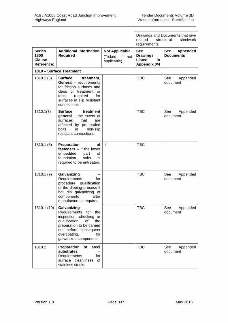
A19 / A1058 Coast Road Junction Improvement Tender Documents Volume 3D Highways England Works Information - Specification
Version 1.0 Page 337 May 2015
Drawings and Documents that give related structural steelwork requirements
Series 1800 Clause Reference:
Additional Information Required
Not Applicable (Ticked if not applicable)
See Drawings Listed in Appendix 0/4
See Appended Documents
1810 – Surface Treatment
1810.1 (5) Surface treatment, General – requirements for friction surfaces and class of treatment or tests required for surfaces in slip resistant connections
TBC See Appended document
1810.1(7) Surface treatment general – the extent of surfaces that are affected by pre-loaded bolts in non-slip resistant connections.
TBC See Appended document
1810.1 (8) Preparation of fasteners – if the lower embedded part of foundation bolts is required to be untreated.
√ TBC
1810.1 (9) Galvanizing – Requirements for procedure qualification of the dipping process if hot dip galvanizing of components after manufacture is required.
TBC See Appended document
1810.1 (10) Galvanizing – Requirements for the inspection, checking or qualification of the preparation to be carried out before subsequent overcoating, for galvanized components.
TBC See Appended document
1810.2 Preparation of steel substrates – Requirements for surface cleanliness of stainless steels.
TBC See Appended document

A19 / A1058 Coast Road Junction Improvement Tender Documents Volume 3D Highways England Works Information - Specification
Version 1.0 Page 338 May 2015
Drawings and Documents that give related structural steelwork requirements
Series 1800 Clause Reference:
Additional Information Required
Not Applicable (Ticked if not applicable)
See Drawings Listed in Appendix 0/4
See Appended Documents
1810 – Surface Treatment Continued
1810.2 (1) Preparation of steel substrates – requirements for the preparation of surfaces to receive corrosion protection if they are to be different from those described in Series 1900 and/or BS ENISO 8501-3:2007 preparation grade P3.
TBC See Appended document
1810.3 Weather resistant steels – requirements for the surface treatment of non-weather resistant steels in contact with uncoated weather resistant steels.
√ TBC
1810.5 Galvanizing – where enclosed spaces shall be sealed after galvanizing and, if so, with what sealant.
TBC See Appended document
1810.6 Sealing of spaces – where weld imperfections permitted by the welding procedure specification require sealing by application of suitable filler material.
TBC See Appended document
1810.6 Sealing of spaces – the method to be used for sealing the interface if mechanical fasteners penetrate the wall of sealed enclosed spaces.
√ TBC
1810.6 (2) Sealing of spaces – internal spaces that are to be hermetically sealed.
√ TBC

A19 / A1058 Coast Road Junction Improvement Tender Documents Volume 3D Highways England Works Information - Specification
Version 1.0 Page 339 May 2015
Drawings and Documents that give related structural steelwork requirements
Series 1800 Clause Reference:
Additional Information Required
Not Applicable (Ticked if not applicable)
See Drawings Listed in Appendix 0/4
See Appended Documents
1810 – Surface Treatment Continued
1810.7 Surfaces in contact with concrete – specific requirements for coating surfaces in contact with concrete.
TBC See Appended document
1810.9 (2) Repairs of coatings to precoated constituent products – method and extent of repair after welding.
TBC See Appended document
1810.10.2 Cleaning of stainless steel components – the method, level and extent of cleaning of stainless steels.
√ TBC
1811 – Geometrical Tolerances
1811.1 Tolerance types – additional information related to special tolerances if these tolerances are specified.
TBC See Appended document
1811.3.3 Alternative criteria – where the specified alternative criteria for functional tolerances may be applied.
TBC See Appended document
1812 – Inspection, Testing and Correction
1812.2.1 (1)
Constituent products – specific testing requirements for proprietary products.
TBC See Appended document
1812.5.1 Inspection of non-preloaded bolted connections – requirements for checking the installation of an insulation system.
TBC See Appended document

A19 / A1058 Coast Road Junction Improvement Tender Documents Volume 3D Highways England Works Information - Specification
Version 1.0 Page 340 May 2015
Drawings and Documents that give related structural steelwork requirements
Series 1800 Clause Reference:
Additional Information Required
Not Applicable (Ticked if not applicable)
See Drawings Listed in Appendix 0/4
See Appended Documents
1812 – Inspection, Testing and Correction Continued
1812.5.2.1 Inspection of friction surfaces – requirements for the inspection and testing of preloaded bolts used for stainless steels connections.
√ TBC
1812.5.5.1 Special fasteners and fastening methods, General – requirements for the inspection of connections using special fasteners or special fastening methods.
√ TBC
1812.7.1 (1)
Inspection of trial erection – additional requirements for the inspection of a trial erection
TBC See Appended document
1812.7.3.4 Location and frequency – additional measurements, other than the position of components adjacent to site interconnection nodes.
TBC See Appended document
1812.7.3.4 Location and frequency – conditions other than under the self weight of steelwork, under which positional measurements should be made.
TBC See Appended document

A19 / A1058 Coast Road Junction Improvement Tender Documents Volume 3D Highways England Works Information - Specification
Version 1.0 Page 341 May 2015
Drawings and Documents that give related structural steelwork requirements
Series 1800 Clause Reference:
Additional Information Required
Not Applicable (Ticked if not applicable)
See Drawings Listed in Appendix 0/4
See Appended Documents
1812 – Inspection, Testing and Correction Continued
1812.7.3.6 Definition of nonconformity – envelope of permissible positions where significant movement of a structure is anticipated.
TBC See Appended document
1812.7.4 Other acceptance tests – specific requirements including tolerance range on the load, if components of a structure are to be erected to a specific load.
TBC See Appended document
2. GeneralThis Appendix 18/1 has been prepared in accordance with BS EN 1090-2 and shall be read as an appended document to the Appendix 18/1 table given in the Specification for Highway Works.
2.2 In addition to the normative references in BS EN 1090-2, the following documents are referred to in this Specification:
(i) NHSS 19A National Highways Sector Schemes for Quality Management in Highway Works, 19A, for corrosion protection of ferrous materials by industrial coatings, UKAS, ISSUE 8-2014.
(ii) NHSS 20 National Highways Sector Schemes for Quality Management in Highway Works, 20, The execution of steelwork in transportation infrastructure assets, UKAS, ISSUE 6 2014.
(iii) EN ISO 8501-1:2007 Preparation of steel substrates before application of paints and related products. Visual assessment of surface cleanliness. Rust grades and preparation grades of uncoated steel substrates and of steel substrates after overall removal of previous coatings.
(iv) BS 8500-1:2006 +A1: 2012 concrete complementary British Standard to BS EN 206-1 –Part 1 Method of Specifying and Guidance for the Specifier.
(v) PD 6705-2:2010+A1: 2013 Published document Structural use of steel and aluminium part 2: Recommendations for the execution of Steel bridges to BS EN 1090 -2.

A19 / A1058 Coast Road Junction Improvement Tender Documents Volume 3D Highways England Works Information - Specification
Version 1.0 Page 342 May 2015
(vi) Several Parts of the Eurocodes are also referenced; in each case, the relevant UK National Annex should be consulted.
2.3 No terms additional to those in BS EN 1090-2 are defined in this Specification.
2.4 The requirements for the execution of structural steelwork shall be given in the Approval in Principle and as shown on the structures drawings listed in Appendix 0/4 of this Specification.
2.5 The designs are based on the construction methods and / or sequences stated on the scheme drawings.
2.6 Fabrication drawings or the equivalent shall be provided to the Project Manager in accordance with Appendix 1/4 of this Specification prior to execution of work.
2.7 Exposure class EXC3 shall generally apply, except where specified otherwise on the drawings.
3. Identification, Inspection and Traceability 3.1 The Contractor shall maintain records of the source of, and test certificates
for, main structural steel elements as follows:
(i) For RHS/SHS/CHS sections, records shall be maintained for each individual piece. A unique item mark shall be made on each piece.
(ii) For deck plates, stiffeners, splice plates, bracing members, and fasteners, the records shall be maintained for each item type. Products of one type may come from more than one source and be installed in more than one location.
(iii) For welding consumables, the records shall be maintained in accordance with stock certification, which shall show that the stock material meets the project requirements as stated on the scheme drawings.
4. Constituent Steel Products 4.1 The grade and quality of structural steel shall be detailed on the structures
drawings.
4.2 Structural steel products shall conform to the requirements of tables 2, 3 & 4 of BS EN 1090-2 unless otherwise specified. Hollow sections shall conform to EN 10210-1 S355J2H and all other steel shall conform to EN 10025-2 S355 J2+N unless otherwise noted.
4.3 Structural steel plates shall be thickness class A in accordance with EN 10029.
4.4 The surface condition shall comply with Class A3 (for flat products) or Class C3 (for sections) to BS EN 10163.
4.5 The surface of the steel material, before surface preparation and protective treatment, shall comply with rust grades A or B in accordance with EN ISO 8501-1. Material which is pitted, i.e. rust grades C or D, shall not be used.
4.6 The Contractor shall ensure that there is no risk of lamerral tearing of any of the materials used in the Works.
4.7 The locations where internal discontinuity quality class S1 is required are specified on the relevant drawings.

A19 / A1058 Coast Road Junction Improvement Tender Documents Volume 3D Highways England Works Information - Specification
Version 1.0 Page 343 May 2015
4.8 Areas where material shall comply with requirements for improved deformation properties perpendicular to the surface according to EN 10164 are specified on the drawings.
4.9 Steel longitudinal beams shall be formed to allow for the pre-camber and to required curvature as detailed on the scheme drawings. The method of achieving the required shape shall eliminate any residual stresses in the steelwork.
5. Welding Consumables 5.1 Welding process 136 is permitted, using one of the options for process 135,
for steels in accordance with EN 10025-5.
6. Mechanical Fasteners 6.1 The property classes of non-preloaded bolts and nuts, and surface finishes,
shall be stated on the scheme drawings.
6.2 The property classes of preloaded bolts and nuts, and surface finishes, shall be HR type conforming to BS EN 14399-3 as detailed on the scheme drawings.
6.3 Reinforcing steels shall not be used for foundation bolts.
6.4 For non-preloaded assemblies, locking devices shall be provided.
7. Grouting Materials 7.1 High strength grouting material / bedding mortar as specified in Appendix
26/1 of this Specification and detailed on scheme drawing shall be used.
8. Identification 8.1 Identification by hard stamping shall only be used in the areas marked on
the drawings.
8.2 Soft or low stress stamps may be used except in any areas specified on the drawings.
9. Cutting 9.1 For carbon steels, hardness of plasma-cut free edge surfaces shall be in
accordance with Table 10 of EN 1090-2, except where all the following apply:
(i) There is no geometrical discontinuity on the surface.
(ii) The surface is not subsequently subject to cold forming.
(iii) Any other surface identified on the drawings.
9.2 Where a hardness limit specified in Table 10 of EN1090-2 is applicable, the processes that are likely to produce local hardness (thermal cutting, shearing, punching) shall have their capability checked. The check of the capability of the processes shall be as specified in Clause 6.4.4.

A19 / A1058 Coast Road Junction Improvement Tender Documents Volume 3D Highways England Works Information - Specification
Version 1.0 Page 344 May 2015
10. Holing 10.1 Holes for fasteners shall be formed by drilling or by punching followed by
reaming.
10.2 Slotted holes shall be executed as specified on the drawings.
10.3 The nominal dimension of countersunk bolts shall be such that the bolt will be flush with the outer face of the outer ply.
11. Cut-outs 11.1 Punched cut-outs shall not be permitted in the Works.
12. Full Contact Bearing Surfaces 12.1 Where full contact bearing is specified, the fit between two surfaces shall be
such that two surfaces mate to give a maximum 0.5 mm gap; the fit may be achieved by machining or grinding.
12.2 Where ends of stiffeners are specified on the scheme drawings as required to be fitted, they shall be ground, where necessary, so that the maximum gap over 60% of the contact area does not exceed 0.25 mm.
13. Assembly 13.1 The acceptability of the addition of any welded temporary attachments and
the making of any butt welds additional to those specified on the scheme drawings shall be verified in accordance with the design rules. A record of the details of such attachments and butt welds shall be provided as part of the Contractors method statement.
13.2 Areas where temporary attachments have been made shall be made good.
13.3 If weld repairs are necessary these shall be carried out in accordance with the requirements of the appropriate European Standard.
13.4 Temporary trial erection of the structure shall be take place at the fabrication yard. The Contractor shall provide details of his proposals for the temporary erection for acceptance by the Project Manager.
13.5 The Contractor shall also provide proposals for the acceptance of the Project Manager for any corrective work required as a result of the temporary erection.
14. Welding 14.1 In general tack welds should be made to the same welding procedure
specification as the permanent welds. If special deposition conditions for tack welds are required, they shall be included in the welding procedure specification.
14.2 For particular joints, detailed on the scheme drawings, pre-production welding tests, qualified in accordance with EN ISO 15613, shall be carried out.
14.3 In general, temporary welded attachments shall not be attached within 25 mm of the edges of flange plates or edge of hollow section curve.
14.4 The use of temporary attachments is permitted as detailed in the scheme drawing.
14.5 Any temporary welded attachments shall be completely removed.

A19 / A1058 Coast Road Junction Improvement Tender Documents Volume 3D Highways England Works Information - Specification
Version 1.0 Page 345 May 2015
14.6 Attachments may be removed by flame cutting not less than 3 mm above the connection on condition that the welded area is subsequently ground flush and checked for cracks using Magnetic Particle Inspection.
14.7 Any welded attachments provided for temporary Works during execution that can, with the agreement of the Project Manager, be left in position, such as lifting cleats on top flanges that are subsequently cast into reinforced concrete, shall be considered as permanent Works and be subjected to appropriate testing and inspection.
14.8 Permanent backing material shall not be used for single sided butt welds.
14.9 For welds on steels with improved atmospheric resistance, C-Mn consumables may be used for single run fillet welds up to 8 mm leg length using welding processes 121, 135 and for butt welds formed by a single run from each side.
14.10 Plug welds shall not be made without previous slot welding.
14.11 Butt welds shall be ground flush only where specified on the scheme drawings.
14.12 The acceptance criteria for imperfection shall be quality level B.
15. Mechanical Fastening 15.1 Non-preloaded bolts shall be provided with locking devices.
15.2 Bolt sizes for structural bolting shall be detailed on the scheme drawings.
15.3 Washers shall be provided under the nut or the bolt head of non-preloaded bolts, whichever is rotated.
15.4 The dimensions and steel grades of plate washers shall be detailed on the scheme drawings
15.5 The area of contact surfaces in preloaded connections shall be detailed on the scheme drawings. If a particular treatment is specified for contact surfaces in slip resistant connections, the treated surfaces shall be adequately protected until they are brought together.
15.6 In addition to the tightening methods in clause 8.5, the part turn method described in 8.505 may be used if the property class 8.8 and assemblies conform to 1805.6.4.
15.7 For the combined method, when using the value Mr,1 for the first tightening step, the simplified expression in clause 8.5.4 of BS EN 1090-2 may be used.
15.8 For the combined method, values given Table 21 of BS EN 1090-2 shall be amended with the value given in Clause 1808.5.4 of the Specification for Highway Works.
15.9 For the HRC method, the first tightening step shall be repeated as necessary if the pre-tightening is relaxed by the subsequent tightening of the remainder of the bolts in the connection.
15.10 Before commencement of preloading, the connected components shall be fitted together and the bolts in a bolt group shall be tightened in accordance with Clause 8.3 of BS EN 1090-2 but the residual gap at the edges shall be limited to 2 mm with the necessary corrective action on steel components.
15.11 Tightening by the part-turn method comprises two steps:

A19 / A1058 Coast Road Junction Improvement Tender Documents Volume 3D Highways England Works Information - Specification
Version 1.0 Page 346 May 2015
(i) A first tightening step, using a torque wrench. The wrench shall be set to a torque value in accordance with Table 18/2 of the Specification for Highways Work. This first step shall be completed for all bolts in one connection prior to commencement of the second step.
(ii) A second final tightening step in which a specified part turn is applied to the turned part of the assembly. The position of the nut relative to the bolt threads shall be marked permanently after the first step, so that the final rotation of the nut relative to the thread in this second step can be easily determined.
15.12 The second step shall be in accordance with the values given Table 18/3 of the Specification for Highways Work.
15.13 Where the part turn method of tightening is adopted, the as-delivered lubrication of high strength bolts for preloading may be altered and to be recorded in HG test report in accordance with BS EN 1090-2.
15.14 The torque method shall not be used for the tightening of preloaded bolts.
16. Erections 16.1 The design is based on the construction method and / or sequences given
on the relevant drawings. All bracings are designed as permanent bracings. The allowances for permanent deformation and other associated dimensions specified on the scheme drawings allow for the following actions, using the design basis method of erection:
(i) After steelwork erection:
a. Self-weight of structural steelwork
(ii) After completion of structure:
a. Self-weight of structural steelwork
b. Self-weight of non-structural parts
16.2 If the Contractor proposes to adopt an alternative construction method and / or sequence to that shown on the contract drawings the Contractor shall verify in accordance with the design rules that the alternative method and / or sequence can be used without detriment to the permanent Works.
16.3 The Contractor shall allow a period of at least six weeks for the acceptance of his erection method statement by the Project Manager.
17. Survey 17.1 The steelwork dimensions on the scheme drawings are specified for a
reference temperature of 12º Celsius.
18. Supports, Anchors and Bearings 18.1 Compensation for settlement of supports shall be made by the Contractor if
such settlement differs from the design assumptions.
18.2 Packing and levelling required during the installation of bridge to be verified in accordance with the construction sequence stated on the relevant drawings. Packing and levelling shall be removed on completion of Work.
18.3 Treatment of steel work, bearing plates and concrete surfaces shall be as specified on scheme drawings.

A19 / A1058 Coast Road Junction Improvement Tender Documents Volume 3D Highways England Works Information - Specification
Version 1.0 Page 347 May 2015
18.4 Area of places where need sealing without grouting shall be specified on drawings.
19. Erection and Work at Site 19.1 Erection method of statement shall be specified on the fabrication drawings
by the Contractor and submitted to the Project Manager for acceptance.
19.2 The erection of the steelwork shall be carried out in accordance with the approved method statement and in such a way as to ensure stability at all times.
19.3 If shims are provided in slip resistant connections, the class of contact surface and surface treatment of the shims shall be the same as for the contact surfaces of the primary components. Shims shall be made of flat steel unless otherwise specified. Shims shall have similar durability to that of the structure.
20. Surface Treatment 20.1 All surfaces shall meet the requirement of BS EN ISO 8501-3: 2007
preparation grade P3 to corrosive category above C3 in accordance with table 22 of BS EN 1090-2.
20.2 All exposed edges that are prepared for coating shall be rounded to a minimum radius of 2 mm.
20.3 Surfaces that shall be in contact with concrete, including parts of the undersides of plates, shall be coated with a protective treatment applied to the steelwork, excluding any cosmetic finishing coat, for a 50mm distance from the exposed edge.
20.4 Areas and surfaces that are difficult to access after assembly shall be coated with a protective treatment before assembly.
20.5 In slip resistance connection, faying surface shall meet the requirements necessary to develop the friction for the specified surface treatment.
20.6 Unless specified otherwise all surfaces shall be treated with the full corrosion protection system.
20.7 Where pre-coated constituent products are welded, all coatings affected by the welding process shall be made good to the original standard.
21. Geometrical Tolerances 21.1 Requirements for special tolerances are given in clauses 11.201 and
11.302.
21.2 The tabulated values in cl D.1 of BS EN 1090-2 shall apply.
21.3 The tolerance on steelwork dimensions and levels at completion shall be as follows:
(i) On level, relative to that specified:
a. At the supports: 5 mm.
b. At mid span: span/1000, up to a maximum of 35 mm.
ii) On level, of one main girder relative to another, adjacent, main girder 20 mm.

A19 / A1058 Coast Road Junction Improvement Tender Documents Volume 3D Highways England Works Information - Specification
Version 1.0 Page 348 May 2015
iii) On plan position of steelwork at bearings (structure at datum temperature): (temporary bearings if used)
Transverse position of bearing top and bottom plates relative to substructure: (temporary bearings if used) ±15 mm
Longitudinal position of bearing top plate relative to bottom plate: (temporary bearings if used) ± (10 mm + Ls/10000)
Where Ls is distance from the fixed point.
21.4 If the steelwork is not within tolerance, it shall be reported to the Project Manager and shall be adjusted at the Contractors expense.
21.5 The tabulated values in cl D.2 of BS EN 1090-2 shall apply and the tolerance class shall be class 1.
22. Inspection, testing and Correction 22.1 Repair by welding on cover plates is not permitted.
22.2 The extent of supplementary Non Destructive Testing (NDT) of the weld shall be as given in Clause 12.4.2.2 and Table 24 of EN 1090-2.
22.3 The frequency of the production tests of the penetration of deep penetration fillet welds shall be defined in the Contractors Inspection and Test Plan.
22.4 The inspection of mechanical fastenings shall be carried out in accordance with the procedure given in clause 12.5.2.3 of BS EN 1090-2. For the torque method, the torque may be applied to the head, if access to apply torque to the nut is not possible. For the part turn method, the first step shall be controlled by use of a calibrated torque wrench. Before the second step starts, the markings of all the nuts relative to the bolt threads shall be visually inspected. Any missing marks shall be corrected. After the second step, the marks shall be inspected with the following requirements:
(i) If the angle of the second step rotation is more than 15° below the specified value, this angle shall be corrected.
(ii) If the angle is more than 30° over the specified angle, or the bolt or the nut has failed, the bolt assembly shall be replaced by a new one.
22.5 Torque value tolerances shall be as stated in clause 8.505.
22.6 All records shall become part of the record of the as-built structure, as required by clause 4.2.4 of BS EN 1090-2.
22.7 Measurements shall be taken on completion of steelwork erection of the position of main booms at Site connections, mid-span, at supports if applicable.
22.8 The positional accuracy of the erected steelwork shall be measured under self-weight of steelwork.

A19 / A1058 Coast Road Junction Improvement Tender Documents Volume 3D Highways England Works Information - Specification
Version 1.0 Page 349 May 2015
APPENDIX 19/1: (SPECIFICATION FOR HIGHWAY WORKS) SHEET NO. FORM HA/P1 (NEW WORKS) PAINT SYSTEM SHEET
Sheet 1: Road Lighting Columns
1. CONTRACT TITLE: STRUCTURE NO: GRID REF:
A19/A1058 Coast Road Junction Improvement Road Lighting Columns N/A
2. DATE OF ISSUE OF DOCUMENTS TO TENDERERS:
3. ENVIRONMENT AND ACCESSIBILITY: Inland and Ready
4. REQUIRED DURABILITY OF SYSTEM: 5. COLOUR OF FINISH:
NO MAINTENANCE: YEARS HA/Aone+ (Area14) - Galvanised with G1 finish for all steel columns. NTC – All columns to be in accordance with NTC specification.
MINOR MAINTENANCE: YEARS
MAJOR MAINTEANCE: YEARS
6. PAINT SYSTEM TO BE APPLIED OVER:
AREA REF: AREA DESCRIPTION:
PROTECTIVE SYSTEM TYPE: (i.e. I, II etc.)
7. DETAILS 1st Coat 2nd Coat 3rd Coat 4th Coat
Registered Description
Item No. and Colour.
BBA HAPAS Roads and Bridges Certificate Reference
Brand Name and Manufacturer’s Ref. No
Manufacturer’s Data Sheet No.
Where applied
How applied
Min dry film thickness (mdft)
Max local dft
Estimated total volume of paint likely to be used (litres)
’A’ type testing required? (YES/NO) (See Cl 1912.3)
’B’ type testing required? (YES/NO) (See Cl 1912.10)
8. STRIPE COAT DESCRIPTION (Including Item No. and colour)
9. PAINT MANUFACTURER’S OFFICIAL STAMP
Workshop:
Site:
10. Mdft (µm) 11. APPROVED BY:
NOTE. The minimum total dry film thickness of the paint system, neglecting primers and sealers under 30 microns, shall be 15% greater (to the nearest 25 microns) than the sum of the mdfts of the individual paint coats. DATE:

A19 / A1058 Coast Road Junction Improvement Tender Documents Volume 3D Highways England Works Information - Specification
Version 1.0 Page 350 May 2015
Sheet 2: Feeder Pillars
1. CONTRACT TITLE: STRUCTURE NO: GRID REF:
A19/A1058 Coast Road Junction Improvement Feeder Pillar NP5 N/A
2. DATE OF ISSUE OF DOCUMENTS TO TENDERERS:
3. ENVIRONMENT AND ACCESSIBILITY: Inland and Ready
4. REQUIRED DURABILITY OF SYSTEM: 5. COLOUR OF FINISH:
NO MAINTENANCE: YEARS Galvanised
MINOR MAINTENANCE: YEARS
MAJOR MAINTEANCE: YEARS
6. PAINT SYSTEM TO BE APPLIED OVER:
AREA REF: AREA DESCRIPTION:
PROTECTIVE SYSTEM TYPE: (i.e. I, II etc.)
7. DETAILS 1st Coat 2nd Coat 3rd Coat 4th Coat
Registered Description
Item No. and Colour.
BBA HAPAS Roads and Bridges Certificate Reference
Brand Name and Manufacturer’s Ref. No
Manufacturer’s Data Sheet No.
Where applied
How applied
Min dry film thickness (mdft)
Max local dft
Estimated total volume of paint likely to be used (litres)
’A’ type testing required? (YES/NO) (See Cl 1912.3)
’B’ type testing required? (YES/NO) (See Cl 1912.10)
8. STRIPE COAT DESCRIPTION (Including Item No. and colour)
9. PAINT MANUFACTURER’S OFFICIAL STAMP
Workshop:
Site:
10. Mdft (µm) 11. APPROVED BY:
NOTE. The minimum total dry film thickness of the paint system, neglecting primers and sealers under 30 microns, shall be 15% greater (to the nearest 25 microns) than the sum of the mdfts of the individual paint coats. DATE:
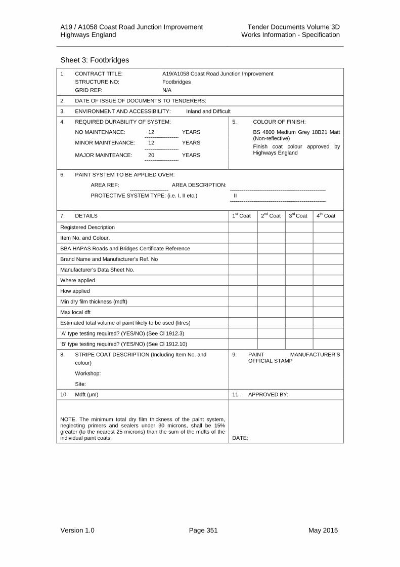
A19 / A1058 Coast Road Junction Improvement Tender Documents Volume 3D Highways England Works Information - Specification
Version 1.0 Page 351 May 2015
Sheet 3: Footbridges
1. CONTRACT TITLE: STRUCTURE NO: GRID REF:
A19/A1058 Coast Road Junction Improvement Footbridges N/A
2. DATE OF ISSUE OF DOCUMENTS TO TENDERERS:
3. ENVIRONMENT AND ACCESSIBILITY: Inland and Difficult
4. REQUIRED DURABILITY OF SYSTEM: 5. COLOUR OF FINISH:
NO MAINTENANCE: 12 YEARS BS 4800 Medium Grey 18B21 Matt (Non-reflective) Finish coat colour approved by Highways England
MINOR MAINTENANCE: 12 YEARS
MAJOR MAINTEANCE: 20 YEARS
6. PAINT SYSTEM TO BE APPLIED OVER:
AREA REF: AREA DESCRIPTION:
PROTECTIVE SYSTEM TYPE: (i.e. I, II etc.) II
7. DETAILS 1st Coat 2nd Coat 3rd Coat 4th Coat
Registered Description
Item No. and Colour.
BBA HAPAS Roads and Bridges Certificate Reference
Brand Name and Manufacturer’s Ref. No
Manufacturer’s Data Sheet No.
Where applied
How applied
Min dry film thickness (mdft)
Max local dft
Estimated total volume of paint likely to be used (litres)
’A’ type testing required? (YES/NO) (See Cl 1912.3)
’B’ type testing required? (YES/NO) (See Cl 1912.10)
8. STRIPE COAT DESCRIPTION (Including Item No. and colour)
9. PAINT MANUFACTURER’S OFFICIAL STAMP
Workshop:
Site:
10. Mdft (µm) 11. APPROVED BY:
NOTE. The minimum total dry film thickness of the paint system, neglecting primers and sealers under 30 microns, shall be 15% greater (to the nearest 25 microns) than the sum of the mdfts of the individual paint coats. DATE:

A19 / A1058 Coast Road Junction Improvement Tender Documents Volume 3D Highways England Works Information - Specification
Version 1.0 Page 352 May 2015
APPENDIX 19/2: REQUIREMENTS FOR OTHER WORK 1. Fasteners 1.1 Unless otherwise specified on the drawings, all new HSFG bolts, nuts and
washers in bridge steelwork shall be hot dipped (spun) galvanised. After the joint is made they shall be prepared and protected as for the joint material. Attention is drawn to the requirements of Clause 1906 of the Specification for Highways Works in respect of application of an adhesion promoter to fasteners before assembly.
1.2 The first coat shall be applied to all galvanised fasteners except for fasteners which have Greenkote® metal coatings as follows:
Shop 1st coat: Item 155, adhesion promoter, applied before joint assembly. The surfaces shall then be rinsed using clean water and dried.
1.3 Form HA/P1 (New Works) Paint System Sheet shall be completed by the Contractor and submitted to the Project Manager.
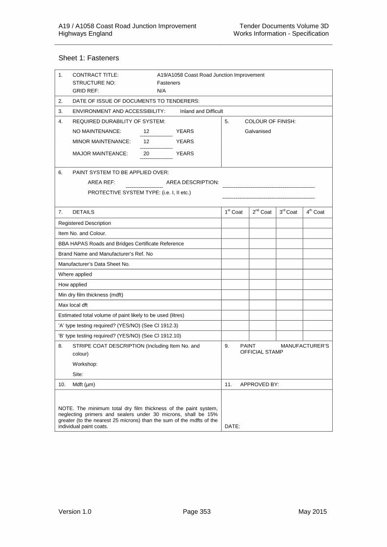
A19 / A1058 Coast Road Junction Improvement Tender Documents Volume 3D Highways England Works Information - Specification
Version 1.0 Page 353 May 2015
Sheet 1: Fasteners
1. CONTRACT TITLE: STRUCTURE NO: GRID REF:
A19/A1058 Coast Road Junction Improvement Fasteners N/A
2. DATE OF ISSUE OF DOCUMENTS TO TENDERERS:
3. ENVIRONMENT AND ACCESSIBILITY: Inland and Difficult
4. REQUIRED DURABILITY OF SYSTEM: 5. COLOUR OF FINISH:
NO MAINTENANCE: 12 YEARS Galvanised
MINOR MAINTENANCE: 12 YEARS
MAJOR MAINTEANCE: 20 YEARS
6. PAINT SYSTEM TO BE APPLIED OVER:
AREA REF: AREA DESCRIPTION:
PROTECTIVE SYSTEM TYPE: (i.e. I, II etc.)
7. DETAILS 1st Coat 2nd Coat 3rd Coat 4th Coat
Registered Description
Item No. and Colour.
BBA HAPAS Roads and Bridges Certificate Reference
Brand Name and Manufacturer’s Ref. No
Manufacturer’s Data Sheet No.
Where applied
How applied
Min dry film thickness (mdft)
Max local dft
Estimated total volume of paint likely to be used (litres)
’A’ type testing required? (YES/NO) (See Cl 1912.3)
’B’ type testing required? (YES/NO) (See Cl 1912.10)
8. STRIPE COAT DESCRIPTION (Including Item No. and colour)
9. PAINT MANUFACTURER’S OFFICIAL STAMP
Workshop:
Site:
10. Mdft (µm) 11. APPROVED BY:
NOTE. The minimum total dry film thickness of the paint system, neglecting primers and sealers under 30 microns, shall be 15% greater (to the nearest 25 microns) than the sum of the mdfts of the individual paint coats. DATE:

A19 / A1058 Coast Road Junction Improvement Tender Documents Volume 3D Highways England Works Information - Specification
Version 1.0 Page 354 May 2015
APPENDIX 19/3: FORM HA/P2 PAINT DATA SHEET
BBA HAPAS Road and Bridges Certificate Reference and Date:
Manufacturer :
Item No. :
Registered Description :
Brand Name and Reference No. :
Consistency and Method of Application :
Weight per 5 Litres (kg)
Specific Gravity: Colour:
For two pack paints :
Base: Activator: Mixed Components:
Volume Solids % :
For two pack paints volume solids % for mixed paints: :
VOC content g/l (mixed) :
Manufacturer’s Minimum Dry Film Thickness Range: :
Recommended lower mdft :
Recommended upper mdft :
Full Application Instruction :
Mix Ratio :
Flash Point :
5ºC 10ºC 20ºC 30ºC
Drying Times (hours)
Surface Dry
Hard Dry
Overcoating Times (hours)
Minimum
Maximum
Pot Life (hours)
Cleaning Solvent :
State effects on Drying Times of Temperatures below 20ºC
:
Manufacturer’s Application Restrictions e.g. for Temperatures or Humidity
:
Manufacturer’s General Recommendations :

A19 / A1058 Coast Road Junction Improvement Tender Documents Volume 3D Highways England Works Information - Specification
Version 1.0 Page 355 May 2015
APPENDIX 19/5: GENERAL REQUIREMENTS 1. The Contractor shall comply with the requirements of Clauses 1902, 1903,
1905, 1906, 1909, 1914, 1915, 1917, 1920 and 1921 of the Specification for Highways Works in the execution and completion of the Works.
2. The paints permitted for use shall be in accordance with Clause 1911 of the Specification for Highways Works except that Type II Aluminium Metal Spray (AMS) system shall not be permitted in the execution and completion of the Works.
3. In lieu of the provision of “A” and “B” samples in accordance with Clause 1912.1 of the Specification for Highways Works, the paint supplier shall provide a Certificate of Conformance to the Project Manager for each type of paint to be used in the works.

A19 / A1058 Coast Road Junction Improvement Tender Documents Volume 3D Highways England Works Information - Specification
Version 1.0 Page 356 May 2015
APPENDIX 20/1: WATERPROOFING FOR CONCRETE STRUCTURES 1. Bridge Deck Waterproofing System 1.1 The Contractor shall comply with Clause 2003 of the Specification of
Highway for Highways Works and IAN 96/07 Rev-1 in the execution and completion of the bridge deck waterproofing Works.
1.2 Immediately before the application of primer or laying of the waterproofing system or protective layer, the concrete surface or primed surface shall be clean, dry and free from ice, frost laitance, loose aggregate, dust and other debris and also where the adhesion to the concrete would be impaired, free from curing liquid compounds and membranes.
1.3 The bridge deck waterproofing system shall be fully covered with tack coat before applying the additional protective layer (APL). The waterproofing system and the APL should be covered as quickly as possible with road surfacing in order to minimise the risk of blistering.
1.4 The Contractor shall only use plant and equipment fitted with rubber tyres for the purpose of laying the APL or any other surfacing material on the bridge deck. Rollers shall not be permitted to stand or travel directly on the water proofing system.
1.5 There are no existing waterproofing systems where repair or replacement is required included in the Works at the time of Tender.
2. Below Ground Level Waterproofing 2.1 All below ground concrete surfaces shall receive two coats of waterproofing
in accordance with Clause 2004 and 2006 of the Specification for Highways Works.
3. Integrity Testing 3.1 Integrity testing of the waterproofing membrane layer shall be carried out
after it has fully cured and before the primer is applied.
3.2 Waterproofing systems to concrete bridge decks shall be integrity tested using a method compatible with the particular system selected. The test method shall be submitted to the Project Manager for acceptance prior to commencement of any such Works.

A19 / A1058 Coast Road Junction Improvement Tender Documents Volume 3D Highways England Works Information - Specification
Version 1.0 Page 357 May 2015
APPENDIX 21/1: BRIDGE BEARING SCHEDULE 2. The Contractor shall execute and complete bridge bearing Works at the
following locations:
(iii) Silverlink A1058 Eastbound Off Slip Footbridge.
(iv) Silverlink A1058 Eastbound On Slip Footbridge.
3. The bridge bearing schedule shall be included on the structures drawings listed in Appendix 0/4 of this Specification.

A19 / A1058 Coast Road Junction Improvement Tender Documents Volume 3D Highways England Works Information - Specification
Version 1.0 Page 358 May 2015
APPENDIX 23/1: BRIDGE DECK EXPANSION JOINTS SCHEDULE 1. The Contractor shall execute and complete bridge deck expansion joint
Works at the following locations:
(i) Tyne Tunnel Central Bridge.
(ii) Silverlink Roundabout North Bridge.
(iii) Silverlink Roundabout South Bridge.
2. All bridge deck expansion joints included in the Works shall satisfy the requirements of BD 33 “Expansion Joints for use in Highway Bridge Decks” of the DMRB.
3. The Contractor shall refer to the structures drawings listed in Appendix 0/4 of this Specification for further details of bridge deck expansion joints.
4. The Contractor shall comply with the requirements of Table 23/1.1 in the provision on bridge deck expansion joints.
Table 23/1.1: Bridge Deck Expansion Joint Requirements
Drawing No. Location Joint Type Horizontal Movement Range (mm)
Vertical Movement Range (mm)
TBC Tyne Tunnel Central Bridge
Asphaltic Plug Joint
± 20 0 / -3
TBC Silverlink Roundabout North Bridge
Asphaltic Plug Joint
± 20 0 / -3
TBC Silverlink Roundabout South Bridge
Asphaltic Plug Joint
± 20 0 / -3

A19 / A1058 Coast Road Junction Improvement Tender Documents Volume 3D Highways England Works Information - Specification
Version 1.0 Page 359 May 2015
APPENDIX 23/2: SEALING OF GAPS SCHEDULE (OTHER THAN IN BRIDGE DECK EXPANSION JOINTS)
1. General 1.1 The Contractor shall execute and complete the sealing of gaps Works at the
following locations:
(i) Tyne Tunnel Central Bridge.
(ii) Silverlink Roundabout North Bridge.
(iii) Silverlink Roundabout South Bridge.
(iv) Silverlink A1058 Eastbound Off Slip Footbridge.
(v) Silverlink A1058 Eastbound On Slip Footbridge.
(vi) All retaining wall capping beams.
1.2 The gaps to be sealed shall be as shown on the structures drawings listed in Appendix 0/4 of this Specification.
2. Filler Requirements 2.1 Joint fillers shall be compressible material complying with clause 1015 of the
Specification for Highway Works.
2.2 Joint filler shall be pre-formed compressible closed cell polyethylene sheet or expanded polystyrene.
3. Sealant Requirements 3.1 Unless noted otherwise on the structures drawings, joints shall be sealed
with polysulphide sealant, applied in accordance with the manufacturer’s instructions.
3.2 The colour of all sealants included in the Works shall be grey.
3.3 Sealants used in the Works shall comply with BS EN IS0 11600:2003.
3.4 The Contractor shall submit the type of joint sealant for acceptance to the Project Manager.
4. Water Stop Requirements 4.1 There are no water stop requirements included in the Works at the time of
Tender.

A19 / A1058 Coast Road Junction Improvement Tender Documents Volume 3D Highways England Works Information - Specification
Version 1.0 Page 360 May 2015
APPENDIX 24/1: BRICKWORK, BLOCKWORK AND STONEWORK 1 There are no locations known at time of Tender where cement for the
purpose of constructing brickwork and blockwork shall be sulphate resistant to BS 4027.
2. Mortar designations shall be Type (i) for all brickwork, blockwork and stonework.
3 There are no additional performance requirements for admixtures other than those stipulated within Clause 2404 of the Specification for Highways Works.
4. All bricks used shall be a Clay Engineering Brick Class B.
5 Bonding for all brickwork and blockwork shall be stretcher bond.
6 All joints in brickwork shall be 10 mm deep struck joints.

A19 / A1058 Coast Road Junction Improvement Tender Documents Volume 3D Highways England Works Information - Specification
Version 1.0 Page 361 May 2015
APPENDIX 25/1: REQUIREMENTS FOR CORRUGATED STEEL BURIED STRUCTURES
1 Design Requirements 1.1 The Contractor shall refer to the Approval in Principal for the Middle Engine
Railway Underpass for details of the design philosophy adopted for the proposed widening Works at Middle Engine Railway (Document Ref: A19T-REP-CIV-S03-2000-0001).
2 Other information 2.1 The Corrugated Steel Buried Structure (CSBS) system that shall be
incorporated in the Works shall have a current Type Approval Certificate and British Board of Agrement Roads and Bridges (BBA) Certificate.
2.2 Material details of the CSBS system are provided below:
(i) Steel grade HR4 to BS 1449: Section 1.1: 1991
(ii) Tolerance to BS EN 10051: 1992
(iii) Minimum yield strength of 229 N/mm2
(iv) Minimum Steel Thickness of 5mm
2.3 The Contractor shall only use grade 10.9 bolts to BS 6104: Part 1: 1981. Bolt lengths shall be sufficient to ensure a full thread in the nut when the plates are drawn together.
2.4 The Contractor shall only use grade 10.9 nuts to BS 6104: Part 2: 1981.
2.5 Bolt tightening values shall be in the range 135 Nm to 270 Nm but shall not be above the maximum torque value of 270 Nm.
2.6 Standard plates shall be pressed, punched then curved to corrugated profile.
2.7 The structural backfill to embankment sections shall be Class 6N in accordance with Table 6/1.1 of this Specification.
2.8 The void between the existing structure and the proposed arch shall be backfilled with class 6N backfill as far as reasonably practical. Where the fill can no longer be adequately compacted due to limited headroom, the remaining void shall then be in-filled with pfa-cement grout.
2.9 The foundation to the CSBS system shall comprise RC concrete springings with mini piled foundations. The concrete and piles shall comply with Appendices 16/1, 16/8, 16/9, 17/1, 17/3, 17/4 and 17/5 of this Specification.
2.10 All surfaces of the steel components shall be hot dip galvanised in compliance with the standards listed in the appropriate Type Approval Certificate and BBA certificate.
2.11 All galvanised steel surfaces of the CSBS shall be protected by an epoxy coating in accordance with the requirement to provide secondary protective coatings to galvanised steel surfaces in accordance with BD12/01 and BD35/06 of the DMRB. The life of this minimum secondary protective coating shall not be taken into account when calculating the required sacrificial steel thickness.

A19 / A1058 Coast Road Junction Improvement Tender Documents Volume 3D Highways England Works Information - Specification
Version 1.0 Page 362 May 2015
APPENDIX 25/5: REQUIREMENTS FOR BURIED RIGID PIPES FOR DRAINAGE STRUCTURES
1. Buried Rigid Pipes Exceeding 900mm Diameter 1.1 Buried rigid pipes exceeding 900mm diameter are shown on the Drainage
Layout drawings A19T-DWG-CIV-S00-0500-0002 – 0006 inclusive. A schedule of these pipes is included in Annex A1, Pipe Schedule of this specification.
1.2 The maximum length of pipe between flexible joints shall not exceed 2.5 m.
1.3 The maximum trench width shall be outside pipe diameter plus 600mm and shall not be exceeded on Site.
1.4 The permitted alternative pipe bedding combinations are shown in the following table. The allowable combinations are the same or higher group than shown specified in the pipe schedule. Limestone aggregate bedding material is not permitted.
Table 25/5.1: Permitted Alternative Pipe Bedding Combinations
Pipe Material
Pre-cast Concrete
Pipe Class
L M H
Bed Type S B S B S B
1050 mm Dia.
4 2 11 8 14 12
1125 mm Dia.
4 2 11 8 14 12
1200 mm Dia.
4 2 11 8 14 12
1.5 To minimise water flows along granular beddings, a 65mm nominal bore weep pipe, 600mm long shall be provided on the upstream side of chamber or headwall as shown on the relevant chamber and headwall drawings.
1.6 Reference to chamber drawings is listed in Appendix 5/1 and in Annex B1 Chamber Schedule of this specification.
1.7 Reference to chamber covers, gratings and frames is listed in Appendix 5/1 and in Annex B1 Chamber Schedule of this specification.
1.8 The hydraulic design relating to drainage pipes and storage tanks is referred to in the Design Input Statement.

A19 / A1058 Coast Road Junction Improvement Tender Documents Volume 3D Highways England Works Information - Specification
Version 1.0 Page 363 May 2015
APPENDIX 26/1: ANCILLARY CONCRETE 1. The Contractor shall provide ancillary concrete at, but not limited to, the
following locations:
(i) Tyne Tunnel Central Bridge.
(ii) Silverlink Roundabout North Bridge.
(iii) Silverlink Roundabout South Bridge.
(iv) Silverlink A1058 Eastbound Off Slip Footbridge.
(v) Silverlink A1058 Eastbound On Slip Footbridge.
(vi) Kerb and Combined Kerb Drainage Unit foundations.
(vii) Lighting and CCTV Columns and Sign Post foundations.
2. The ancillary concrete for structures shall be as shown on the structures drawings listed in Appendix 0/4 of this Specification.
3. Blinding concrete and concrete for back of wall drainage bedding shall be Class FND 3z concrete and shall be in accordance with Table A.13, BS8500 Part 1: 2006.
4. Concrete infill to verges / footways, concrete for protection to waterproofing, if required, shall be class ST2 concrete and shall comply with Table 26/1.1 below.
5. Joint and Rolling block concrete for supporting Asphaltic Plug Joints shall be class ST4 concrete and shall comply with Table 26/1.1 below.
6. All concrete for ancillary purposes shall conform to Clauses 2601 and 2602 of the Specification for Highways Works.
7. All porous no fines concrete shall conform to Clause 2603 of the Specification for Highways Works.

A19 / A1058 Coast Road Junction Improvement Tender Documents Volume 3D Highways England Works Information - Specification
Version 1.0 Page 364 May 2015
Table 26/1.1: Ancillary Concrete Mix Requirements Standardized Prescribed Concrete ST1 ST2 ST5
Requirement to conform to BS 8500-2 Yes Yes Yes
Alternative strength class for designated concrete
GEN0 GEN1 FND
Strength class that may be assumed for structural design.
C6/8 C8/10 C20/25
Characteristic compressive cube strength at 28 days that may be assumed (N/mm2)
8 10 25
Chloride Content Cl 0,10 Cl 0,10 Cl 0,10
Required Type and Class of Cement: BS 4027, SPRY
BS 4027, SPRY
BS 4027, SPRY
Types of Aggregate: All aggregates to comply with BS 8500:2
All aggregates to comply with BS 8500:2
All aggregates to comply with BS 8500:2
Maximum aggregate size 20mm 20mm 20mm
Concrete Unreinforced Unreinforced Unreinforced
Slump class S1 S2 S3

A19 / A1058 Coast Road Junction Improvement Tender Documents Volume 3D Highways England Works Information - Specification
Version 1.0 Page 365 May 2015
APPENDIX 26/2: BEDDING MORTAR 1. The Contractor shall provide bedding mortar to place precast prestressed
concrete beams at the following locations:
(i) Tyne Tunnel Central Bridge.
(ii) Silverlink Roundabout North Bridge.
(iii) Silverlink Roundabout South Bridge.
2. The use of non-flowing or dry pack mortars as bedding mortars underneath the bottom of precast prestressed concrete beams shall be permitted. The Contractor shall refer to additional Clause 2608AR in Appendix 0/1 of this Specification for further details.
3. Resinous bedding mortar shall at no time be subjected to a loading which will induce a compressive stress exceeding 0.25 of its compressive strength
4. Cementitous bedding mortar shall at no time be subjected to a loading which will induce a compressive stress exceeding 0.4 of its compressive strength.
5. Rapid Set Mortars shall comply with the following: Table 26/2.1: Bedding Mortar Mix Requirements Components Mixture of cements, fine aggregates, additive,
activator and/or clean potable water
Workability Time: 10 + 5 minutes
Initial Setting Time: 25 + 10 minutes
Layer Thickness Range: 2 to 40mm
Temperature Range: -10 to +30_C
Colour: Grey
Compressive Strengths:
1 Hour 20 + 5N/mm2
2 Hours 30 + 10N/mm2
3 Hours* 40 + 5N/mm2
28 Days 70 + 5N/mm2
Tensile Strength*: Greater than 8 MPa
* - Resinous bedding mortars only
1. Permanent metal shims shall be acceptable underneath chamber cover frames and gully grating frames at each corner.
2. Bedding mortars may be loaded once they shall have achieved a minimum compressive strength of 40 N/mm2.
3. Four mortar cubes shall be made for each pour of mortar in accordance with Clause 2601 of the Specification for Highways Works.
4. The mortar cubes shall be tested for compressive strength in sets of two, at times determined by the Contractor, until the compressive strength of both cubes in a set is not less than 40N/mm2.

A19 / A1058 Coast Road Junction Improvement Tender Documents Volume 3D Highways England Works Information - Specification
Version 1.0 Page 366 May 2015
APPENDIX 26/3: CORED THERMOPLASTIC NODE MARKERS 1. The Contractor shall execute and complete thermoplastic node markers in
accordance with the requirements of Clause 2606 of the Specification for Highways Works.
A19 / A1058 Coast Road Junction Improvement Tender Documents Volume 3D Highways England Works Information - Specification
Version 1.0 Page 367 May 2015
APPENDIX 30/1: GENERAL 1. Notice and Liaison 1.1 Forty eight hours’ notice period shall be required for the operations listed in
Clause 3001.2 of the Specification for Highways Works.
1.2 The location and extent of Sites of nature conservation and / or archaeological interest that lie adjacent or close to either the existing or proposed highway boundary and may be vulnerable to the Works are detailed in the Environmental Assessment Report (Ref: )
1.3 Badger setts, soft estate areas where reptile and great crested newts are known to be present and other features of ecological importance, such as bats and water voles, are also detailed in the Environmental Assessment Report (Ref: ).
2. Peat 2.1 Peat or peat-based products shall not be used.
3. Pesticide Application 3.1 Pesticide Record Forms on the following pages shall be submitted by the
Contractor at monthly intervals, or within one month of application if less frequent. They shall set out, as a minimum, the level of information specified in Clause 3001.13 of the Specification for Highways Works.
4. Bird Nesting Season 4.1 The bird nesting season shall be from the 1st March to 1st September.
Vegetation shall not be removed or disturbed during this period. If this is unavoidable, then an ornithological check shall be carried out to ensure that there are no nests in the vegetation to be removed.
4.2 When there is a requirement for any such Works that may cause disturbance to nesting birds outside of this season and weather conditions have been such that the Environmental Manger considers that there may be a possibility of nesting birds, an ornithological check shall be carried out prior to commencement of the Works to ensure there are no nests in the vegetation to be removed.
4.3 If nesting birds are discovered within the Works area or close to it, the location of the nest must be left, with an agreed buffer zone of vegetation, as advised by the Ecologist. This location / area of vegetation shall only be entered or disturbed when the nest is no longer in use.
5. Inspection Reports 5.1 The Contractor shall maintain the new planting, newly seeded areas,
existing and retained woody vegetation as detailed within this Specification throughout the 5 year Defects Liability and Establishment Period (the ‘Aftercare Period’).
5.2 Visits shall be made on a minimum of a monthly basis. Inspection Reports shall be submitted by the Contractor at monthly intervals during this period. The reports shall identify the level of work activities undertaken for each operation on the Landscape Works - Inspection Report form.

A19 / A1058 Coast Road Junction Improvement Tender Documents Volume 3D Highways England Works Information - Specification
Version 1.0 Page 368 May 2015
6. Risk Assessments 6.1 The Contractor shall submit Risk Assessments and Methods Statements for
each of the operations listed in Clause 3001.2 of the Specification for Highways Works.
6.2 The Contractor shall also submit Risk Assessments and Methods Statements for specific risks / methods associated with working:
(i) adjacent to sensitive locations.
(ii) within translocated woodlands.
(iii) within areas of retained on-Site vegetation.
(iv) on embankments/cuttings.
(v) above / close to retaining structures.
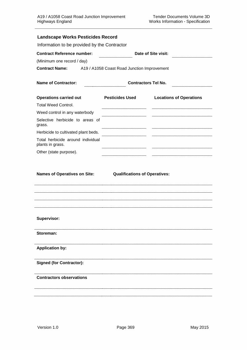
A19 / A1058 Coast Road Junction Improvement Tender Documents Volume 3D Highways England Works Information - Specification
Version 1.0 Page 369 May 2015
Landscape Works Pesticides Record Information to be provided by the Contractor
Contract Reference number: Date of Site visit:
(Minimum one record / day)
Contract Name: A19 / A1058 Coast Road Junction Improvement
Name of Contractor: Contractors Tel No.
Operations carried out Pesticides Used Locations of Operations
Total Weed Control.
Weed control in any waterbody
Selective herbicide to areas of grass.
Herbicide to cultivated plant beds.
Total herbicide around individual plants in grass.
Other (state purpose).
Names of Operatives on Site: Qualifications of Operatives:
Supervisor:
Storeman:
Application by:
Signed (for Contractor):
Contractors observations

A19 / A1058 Coast Road Junction Improvement Tender Documents Volume 3D Highways England Works Information - Specification
Version 1.0 Page 370 May 2015
Landscape Works Inspection Report Information to be provided by the Contractor
Contract Reference number: Date of Site visit:
(Minimum one record / day)
Contract Name: A19 / A1058 Coast Road Junction Improvement
Name of Contractor: Contractors Tel No.
Operations carried out Locations of Operations
Names of Operatives on Site: Qualifications of Operatives:
Contractors observations on damage by others, additional work required or general condition of the Works:
Observations of the Project Manager on standards of workmanship, additional work required or general condition of the Works
This maintenance visit has been successfully completed:
Signed (for Contractor):
Name: Date:
Signed (for Project Manager):
Name: Date:

A19 / A1058 Coast Road Junction Improvement Tender Documents Volume 3D Highways England Works Information - Specification
Version 1.0 Page 371 May 2015
APPENDIX 30/2: WEED CONTROL 1. General 1.1 Weed control regimes detailed below shall be applied to areas of proposed
seeding and planting, (on Site and woodland creation) and to existing grasslands throughout the Maintenance Period.
1.2 The Landscape Contractor shall carry out weed control to the injurious species listed below and refer to the Invasive Species Identification and Control Technical Specification
(i) Broad Leaf Dock
(ii) Curcle Dock
(iii) Common Ragwort
(iv) Creeping tistle
(v) Spear thistle
(vi) Himalayan Balsam
(vii) Giant Hogweed
(viii) Japanese Knotweed
1.3 Weed control of any other injurious species shall be carried out over the entire contract area three times during the active growing season throughout the Maintenance Period, or as required to ensure effective control of each species. The Environmental Manager shall instruct when these operations shall be carried out and adjust the frequency.
1.4 Inspection and Maintenance Reports shall be submitted in accordance with Clause 3001.15 of the Specification for Highways Works and as described in Appendix 30/1.
2. Total Weed Control 2.1 Residual herbicides shall be applied to all areas of hard standing and gravel
areas.
2.2 Total weed control as Site preparation shall be carried out, as required, to achieve weed free ground conditions to all areas of proposed grassland (including proposed tree planting areas and any re-enforced / steepened slopes), wildflower grassland and proposed heathland. Extent of required control will be dependent upon timing of earthworks and seeding seasons and the extent is to be agreed with the Environmental Manager, dependent upon cover at the time of proposed seeding.
2.3 Total weed control shall be carried out to any existing open drainage ditches, pollution control ditches, filter drains etc. to ensure that the weed growth is not impeding the drainage system. This shall be carried out as necessary in locations and at frequencies instructed by the Environmental Manager. Where herbicide application is required adjacent to, or in close proximity to, existing drainage features, water bodies or watercourses, the type of herbicide and frequency of application shall be to the approval of the Environment Agency.
A19 / A1058 Coast Road Junction Improvement Tender Documents Volume 3D Highways England Works Information - Specification
Version 1.0 Page 372 May 2015
3. Selective Weed Control in Grass 3.1 Targeted weed control shall be carried out to all newly seeded verges,
heathland and grassland areas, (once established), all newly planted areas, (including woodland creation areas) and around waterbodies, (using appropriate herbicides). Frequency shall be determined by the Environmental Manager, dependent upon extent of broadleaved weeds and degree of previous control. Selective herbicides shall not be used in Wildflower grassland areas.
4. Weed Control by Spot Application of Herbicide 4.1 Weed control by spot application of herbicide shall be carried to all injurious
weeds including the following locations/species throughout the Maintenance Period:
(i) Common Ragwort rosettes from mid-April to the end of May in locations agreed with the Environmental Manager. The contractor shall refer to the ‘Code of Practice on how to ‘Prevent the Spread of Ragwort’, published by DEFRA, and adhere to guidance therein.
(ii) Japanese knotweed, as necessary, in locations agreed with the Environmental Manager.
(iii) Other injurious weeds as necessary, in locations agreed with the Environmental Manager.
5. Weed Control by Pulling / Hand Weeding 5.1 Weed control by hand pulling shall be carried out to:
(i) Any remaining Common Ragwort during the active growing season and before the plants set seed in June / July in locations agreed with the Environmental Manager. Operatives carrying out the work shall wear protective clothing as necessary to ensure that there is no contact with the weed or sap from the weed.
(ii) Tree shelters.
(iii) Wildflower / Species Rich Grasslands.
6. Weed Control by Cutting 6.1 Any weeds not controlled by the above operations shall be controlled by
cutting / strimming prior to setting seed.
7. Arising’s from Weed Control Operations 7.1 Arising’s from hand weeding Common Ragwort shall be removed from Site.
7.2 Arising’s from control of Japanese knotweed shall be disposed of as set out in a methodology to be submitted by the Contractor.
7.3 Any such arisings from non-injurious Weeds collected shall be removed to tip from the Site.

A19 / A1058 Coast Road Junction Improvement Tender Documents Volume 3D Highways England Works Information - Specification
Version 1.0 Page 373 May 2015
APPENDIX 30/3: CONTROL OF RABBITS AND DEER 1. General 1.1 All areas within the new highway boundary and woodland creation areas
shall be subject to Rabbit Control prior to the first planting season. The contractor shall provide this in accordance with Clauses 3003.1 to 3003.13 of the Specification for Highways Works.
1.2 Joint inspections shall be undertaken at three monthly intervals between the Contractor and Environmental Manager.
1.3 The time period shall be from the commencement of the contract until Practical Completion and for a further 60 months until Final Completion.

A19 / A1058 Coast Road Junction Improvement Tender Documents Volume 3D Highways England Works Information - Specification
Version 1.0 Page 374 May 2015
APPENDIX 30/4: GROUND PREPARATION 1. General 1.1 Requirements for topsoil and subsoil shall be in accordance with the
requirements of Appendix 6/8 – Topsoil and shall be completed prior to the landscape contract commencing.
1.2 The location of areas in which existing topsoil and vegetation shall be left in place and where topsoil shall be stripped as turf are shown on Drawings Ref. A19T-DWG-CIV-S00-0600-0001 to 0007 inclusive.
1.3 The location of potentially suitable Class 5A materials is identified on Drawings Ref. A19T-DWG-CIV-S00-0600-0001 to 0007 inclusive.
1.4 If there is insufficient topsoil arising on Site, the Contractor shall import Class 5B topsoil that shall comply with BS 3882:2007.
1.5 Topsoil and subsoil finishes are as follows:
(i) Wildflower grassland – this shall be generally sown on subsoil’s that has been broken up and which has had stones over 75mm removed. Subsoil should be 75 - 125mm depth of approved Site-won subsoil. 50mm of topsoil can be implemented on steeper soils to ensure stability. Detail is provided in Appendix 30/5.
(ii) General grasslands, grass verges - minimum 75 - 125mm of topsoil or approved Site- won sub-soil.
(iii) Tree planting plots (Newly topsoiled) – Minimum 300mm depth topsoil on suitable subsoil or agreed structural sub-base material.
2. Vegetation Clearance 2.1 Any grass and herbaceous vegetation in areas of proposed tree and shrub
planting and seeding shall be cut in accordance with Clause 3004.1 of the Specification for Highways Works.
2.2 The Contractor shall consult and comply with the Environmental Manager to determine the extent of areas requiring vegetation clearance. If vegetation clearance is necessary, it shall be instructed by the Environmental Manager. If no cutting is deemed necessary, the Contractor shall confirm that he is happy with the surface finish for preparation of seed beds.
2.3 The Environmental Manager shall consult the Ecologist prior to vegetation clearance in planting or seeding areas to determine whether there are any ecological constraints to the cutting and adopt any particular working practices recommended by the Ecologist in any such vegetation clearance.
2.4 Herbicide shall be applied in accordance with sub-Clause 3002.4 of the Specification for Highways Works.
3. Subsoil Treatment 3.1 Subsoil and topsoil shall not be handled when the soil shall be waterlogged,
when the moisture content of the soil exceeds its Plastic Limit as defined in BS 1377: 1990 during precipitation or until at least two hours have passed after light rainfall (less than 2 mm in any one hour) or at least four hours have passed after heavy rainfall (more than 2 mm in any one hour), or as directed by the Project Manager.

A19 / A1058 Coast Road Junction Improvement Tender Documents Volume 3D Highways England Works Information - Specification
Version 1.0 Page 375 May 2015
3.2 The Contractor shall carry out subsoil cultivation / decompaction in accordance with Clauses 3004.5 and 3004.6 of the Specification for Highways Works.
3.3 Subsoil decompaction shall be carried out when the soil shall be in a dry condition in order to achieve maximum heave.
3.4 On steep slopes, avoid over-compaction of sub-soil layers and place topsoil in uncompacted layers.
4. Final Preparation of Soils 4.1 Final preparation of soils for planting and seeding shall be in accordance
with the requirements of Clauses 3004.8 to 3004.11 of the Specification for Highways Works. This applies to all areas to be planted or seeded and all areas of subsoil and topsoil, not only compacted material.
4.2 Clause 3004.9 of the Specification of Highways Works shall not apply.
4.3 Finished levels of material after settlement shall be at the same level as adjoining areas.
4.4 Unless otherwise stated in the Contract, finished levels of grass areas shall be 30 mm above adjoining paving or kerbs; 150 mm below the damp proof course of adjoining buildings and not more than 75 mm above previous soil levels at butt of existing trees.
4.5 Levels shall be arranged to give gentle falls for drainage and to avoid ponding hollows.
4.6 Where finished levels shall not have been given in the Design, the levels shall be such that the finished surface shall have a smooth even fall (or gently rolling curve if shown) between the finished levels on the boundaries of the areas.
4.7 Any area unduly compacted during the work or grading shall be loosened by forking or harrowing.
4.8 The use of heavy rollers to roll out mounds shall not be permitted, and if a panned layer shall be found in the surface soil the seed bed shall be rectified.

A19 / A1058 Coast Road Junction Improvement Tender Documents Volume 3D Highways England Works Information - Specification
Version 1.0 Page 376 May 2015
APPENDIX 30/5: GRASS SEEDING, WILDFLOWER SEEDING AND TURFING
1. Season 1.1 Wildflower seed shall be sown in September / October (optimum season) or
March to May depending on the construction programme and availability of areas. Grass seed shall be sown in March to May or September / October.
1.2 Grass and / or wildflower seeding may be undertaken outside of these periods if instructed by the Environmental Manager.
2. Final Cultivations 2.1 Final cultivations shall be carried out to all areas to be seeded in accordance
with Clause 3005.2 of the Specification for Highways Works immediately prior to sowing.
2.2 The Contractor shall submit a method statement for the preparation of any areas that shall have slopes steeper than 1:2, which are too steep for mechanical cultivations, and / or hydraulically seeded areas which may be stony or rocky.
2.3 All areas to be turfed or seeded shall be finely graded to bring them to a uniform and even grade at the correct finished levels and remove all minor hollows and ridges.
2.4 Final grading shall be to smooth, flowing contours, and shall be agreed with the Project Manager.
2.5 Where new grass shall be sown adjoining existing turf or any other edging material, the surface shall grade evenly into the other material.
2.6 In the case of grass, the cultivation operations shall be extended not less than 600 mm into the existing grass areas to achieve proper marrying-in.
2.7 For general grasslands, pre-seed Fertiliser is to be applied to Highway Mix grass seed areas only. This shall be N:P:K 6:9:6 or equivalent, at a rate of 25 g/m2. Any equivalent is subject to approval by the Environmental Manager.
2.8 Fertilisers shall not be used in areas of wildflower / heathland grassland.
2.9 During and after cultivation, the areas to be seeded shall not be traversed by the Contractors plant except those necessary for seeding and planting Work, and such trafficking shall be kept to a minimum.
3. Seed 3.1 The following seed mixes shall be used in areas shown on the Landscape
layout plans (Ref: A19T-DWG-CIV-S00-3000-0001 to 0007 inclusive), to areas of new grasslands, wildflower grassland, heathland, proposed planting plots and pond margins, these have been agreed with the Ecologist but are subject to change dependant on Site conditions

A19 / A1058 Coast Road Junction Improvement Tender Documents Volume 3D Highways England Works Information - Specification
Version 1.0 Page 377 May 2015
(i) Highway Mix. DLF Trifolium PRO 85 DOT, or equal approved by the Environmental Manager to general grassland areas, grass verges and proposed tree and shrub planting plots.
Percentage
25 ESQUIRE PERRENIAL RYEGRASS
20 MAXIMA STRONG CREEPING RED FESCUE
30 TRIANA HARD FESCUE
10 EVORA SMOOTH STALKED MEADOW GRASS
10 HIGHLAND BROWN TOP BENT
5 RIVENDEL WHITE CLOVER
100
(ii) Species-rich Mix (SRG)
The mixes Species Rich Grassland, these are subject to approval by ecologist and locations will be decided on Site once soil type is known.
4. Conventional Sowing
4.1 Seed shall be sown at the following rates:
(i) DLF Trifolium PRO 85 DOT (or equal approved) – 20g/m2
(ii) SRG 4g/ m2
5. Hydraulic Seeding 5.1 Hydraulic seeding shall be applied to steep slopes as described in Clause 2
of this Appendix 30/5.
5.2 The overall Hydraulic seeding mulch shall be applied at 100g/m2, giving the same seed sowing rates as for conventional seeding as specified in Clause 4 of this Appendix 30/5.
5.3 The Hydraulic seeding mulch mixture shall be a constitution of Jute or Cotton fibre (by-product of the textile industry) mixed with a binding agent of Guar Gum powder at 5g/m2.
5.4 The Hydraulic seeding mulch mixture is completed with the addition of water producing a homogenous slurry. This homogenous slurry is to be kept constantly stirred during application to prevent separation of the mixture.
5.5 Liquid Slow-Release Fertiliser shall be incorporated with the mulch. This shall be calibrated for an application rate of 20 litre/ha.
5.6 Liquid Slow Release Fertiliser shall only to be used for Highway Seed mixtures.
5.7 Liquid fertiliser shall not be used for Wildflower Seed (SRG) mixtures.

A19 / A1058 Coast Road Junction Improvement Tender Documents Volume 3D Highways England Works Information - Specification
Version 1.0 Page 378 May 2015
5.8 Clauses 3005.12 to 3005.26 inclusive of the Specification for Highways Works shall not apply to this Contract.
6. Establishment Cuts 6.1 Clause 3005.28 of the Specification for Highways Works shall not apply to
this Contract.
6.2 All areas of new grass, including on Site tree planting plots, and wildflower grassland seeding shall be cut as follows during the first twelve months following seeding:
(i) Newly established grassland shall be cut to 50mm when grass exceeds a height of 150mm. Subsequent cuts shall be to a height of 75 - 100mm whenever growth exceeds 150mm. Cutting for the remainder of the Maintenance Period shall be as described in Appendix 30/7 of this Specification. There shall be a maximum of six establishment cuts.
(ii) Wildflower grasslands areas sown in autumn shall be cut in mid-May of the following year. Areas sown in spring shall be cut in late September. Cutting shall be to a height of 75mm with flail mower or tractor mounted rotary cutter. Where wheeled vehicles are used for cutting grass areas they shall have low pressure tyres. Two to three establishment cuts may be needed depending on growth and Site conditions; this shall be agreed with the Environmental Manager.
(iii) Seeding on steepened slopes – the Contractor shall submit his Method Statement for maintenance of steepened slopes. This shall be agreed with the Environmental Manager.
6.3 Arising’s from mowing may be left evenly spread on Site except in wildflower grassland areas (excluding first cut) where they shall be removed and composted in an onsite location agreed with the Environmental Manager or disposed of off Site.

A19 / A1058 Coast Road Junction Improvement Tender Documents Volume 3D Highways England Works Information - Specification
Version 1.0 Page 379 May 2015
APPENDIX 30/6: PLANTING 1. Plants 1.1 The Contractor shall provide all plants as detailed within the planting
schedules as shown on the Landscape layout plans (Ref: A19T-DWG-CIV-S00-3000-0001 to 0007 inclusive).
1.2 Clause 3006.5 of the Specification for Highways Works shall not apply to this Contract.
1.3 Only native plant stock shall be used.
1.4 The National Plant Specification referred to in Clause 3006.8 of the Specification for Highways Works is available electronically at http://www.gohelios.co.uk/.
1.5 The Contractor shall retain all plant labels for a period of twelve months after planting.
1.6 All plants that shall be used in the execution of the Works shall be hardened-off at the source nursery prior to planting out.
1.7 All containerised feathered trees shall have been containerised for a minimum of two growing seasons.
1.8 Feathered trees shall be in minimum 15 litre containers.
1.9 Trees shall be carefully packed prior to transit, either individually or in bundles, with straw and wrapped in hessian to prevent rubbing of branches and drying out of roots (if bare-rooted).
1.10 Any plants packed in crates for transit shall be unpacked immediately or within 24 hours of delivery at the latest.
1.11 The plants shall be carefully checked for damage (breakage and bruising and the like).
1.12 Container-grown plants shall be checked to ensure that the soil and root system shall not be neither dried out nor waterlogged.
1.13 All plant material shall be stored such that they are protected from damage by frost or drying out.
2. Topsoil, Compost, Fertiliser and Anti-Desiccants 2.1 The Contractor shall provide any such imported topsoil in accordance with
BS 3882: 2007 Specification for Topsoil and Requirements for Use.
2.2 Imported topsoil for tree pits shall be Multipurpose Topsoil as defined by the British Standard.
2.3 The Contractor shall be responsible for providing analysis of imported topsoil and interpretation of the results to demonstrate compliance with the British Standard.
2.4 Compost shall be incorporated into the soil during pit / hedge preparation at the following rates:
(i) Compost required at a rate of 24 litres per metre run of hedge trench.
(ii) Planting pits, 3 litres per pit.
A19 / A1058 Coast Road Junction Improvement Tender Documents Volume 3D Highways England Works Information - Specification
Version 1.0 Page 380 May 2015
(iii) Fertiliser to be added to remaining planting plots at 35 gms per pit and in accordance with Clause 3006.15 of the Specification for Highways Works.
2.5 Peat-free organic composted material shall have:
(i) Ph level: 7.0 – 8.7.
(ii) Conductivity: 2000 μS/cm or 200 mS/m max.
(iii) Nutrient composition: N: medium, P: medium, K: high.
2.6 Fertiliser to be Bone meal applied at 35 gm per plant applied to top of all planting stations after planting and lightly forked in.
3. Time of Planting 3.1 Planting shall take place during favourable weather and soil conditions
between the start of November and the end of March.
3.2 Clause 3006.19 of the Specification for Highways Works shall not apply to this Contract.
3.3 All Ilex aquifolium shall be planted 20 - 25mm deeper than the nursery soil mark.
4. Notch Planting of Trees, Shrubs and Hedges 4.1 Planting of bare root material shall be undertaken, in existing / re-spread
soils, using a proprietary tool such as a Canadian Tree Spade. Planting method shall be as follows;
(i) Insert spear vertically, push back and forward slightly and then twist through 180 degrees. In heavy clay it may be necessary to insert again at 90 degrees to the first cut and twist again.
(ii) Adjust the depth of the notch according to the length of the roots. Don't make a deeper notch than necessary. This is to ensure no air pocket is left resulting in roots being suspended and drying out. Crown of bare roots to be level with soil.
(iii) Insert spear about 5 cm toward the planter and pull handle toward planter to firm soil at bottom of plug and close any air pocket.
(iv) Push handle forward to firm soil at top of plug. Close ground with toe taking care not to scuff the plant.
(v) Surrounding soil shall be firmed back after planting.
5. Planting Pits, Beds and Trenches 5.1 Staked selected standard and small feathered trees, container grown trees,
shrubs and any bare rooted whips and transplants not notch planted shall be pit / trench planted in accordance with this clause and Table 30/1 of the Specification for Highways Works:
5.2 Planting Pits, Beds and Trenches. Pits for whips and transplants shall be excavated to the specified dimensions and backfilled with a mixture of topsoil and compost. The Contractor shall import any shortfall in topsoil required to fulfil this requirement.
5.3 Planting Trenches for hedge planting shall be prepared to a width of 600mm and a depth of 300mm. Subsoil shall be broken up to a depth of 150mm.

A19 / A1058 Coast Road Junction Improvement Tender Documents Volume 3D Highways England Works Information - Specification
Version 1.0 Page 381 May 2015
5.4 Surplus arisings (i.e. not topsoil), from all pit excavations shall be spread evenly throughout the planting area unless this is deleterious material. Material shall be spread so that it shall not interfere with any adjacent drainage.
5.5 Clause 3006.27 of the Specification for Highways Works shall not apply to this Contract.
6. Planting in Cultivated Beds and Hedges 6.1 Clause 3006.30 of the Specification for Highways Works shall not apply to
this Contract.
6.2 Where mixes of different shrub and transplant species and varieties shall be planted in one specified area, they shall be distributed in a random manner.
6.3 Random distribution shall be achieved by dispersing and planting individual species across the area in groups. The Contractor shall ensure that no repetitive or recurring patterns shall be achieved in the execution of the Works.
7. Planting of Whips, Transplants and Shrubs into Pits or trenches 7.1 Clauses 3006.49 to 51 inclusive of the Specification for Highways Works
shall not apply to this Contract.
7.2 Transplant and Shrub pits and Tree pits for feathers and whips shall be positioned in rows, each row staggered with the previous row. The rows shall run parallel with the longest boundary of the planting area. Plants shall be spaced at approximately equal centres to obtain a natural dense cover when mature.
7.3 Where an area shall be filled with Shrubs, Climbers and / or Transplants the extent of the area to be filled shall first be defined by plants spaced around the perimeter. The remaining plants shall then be used to fill the centre of the area in an informal manner, avoiding straight line and regular geometric patterns.
7.4 The plants shall be positioned to allow 75 mm clearance between the root-ends when fully spread, or the perimeter of the root-ball and the sides and bottom of the excavated position.
8. Planting of Trees 8.1 Clauses 3006.38 and 43 to 45 inclusive of the Specification for Highways
Works shall not apply to this Contract.
8.2 Pits for selected standard trees in Tree mix areas shall be laid out informally to avoid pits in straight lines.
8.3 No tree shall be planted within 2 m of any footway or road kerb.
8.4 Trees shall be positioned to achieve even spacing and matching of shapes.
9. Tubes, Guards and Ties 9.1 The Contractor shall use ‘Tubex’ or equivalent approved tree shelters 60cm
high with an internal diameter of 200mm supported by a Sweet Chestnut pail approx. 90 cm high, 20 - 30mm diameter with two releasable ratchet ties for all deciduous tree and shrub transplants.
9.2 Evergreens species shall have polypropylene mesh guards minimum 600mm high.

A19 / A1058 Coast Road Junction Improvement Tender Documents Volume 3D Highways England Works Information - Specification
Version 1.0 Page 382 May 2015
9.3 Standard and feathered trees shall have spiral guards minimum 600mm high.
10. Mulches: Ground Preparation 10.1 Clause 3006.53 of the Specification for Highways Works shall not apply to
this Contract.
11. Organic Mulches 11.1 Clauses 3006.54 to 57 inclusive of the Specification for Highways Works
shall not apply to this Contract.
12. Individual Mulch Mats 12.1 Clauses 3006.58 to 60 inclusive of the Specification for Highways Works
shall not apply to this Contract.
13. Sheet Mulch 13.1 Clauses 3006.61 to 64 inclusive of the Specification for Highways Works
shall not apply to this Contract.
14. Planting of Bulbs 14.1 Clauses 3006.65 to 67 inclusive of the Specification for Highways Works
shall not apply to this Contract.
14.2 Bulbs shall be thrown on the ground in loose drifts in areas indicated to ensure ‘natural’ spacing.
15. Wildflower Plant Preparation and Planting 15.1 Clauses 3006.68 to 72 inclusive of the Specification for Highways Works
shall not apply to this Contract.
16. Planting of Reeds, Rushes, Marginal, Emergent and Aquatic Plants 16.1 Clause 3006.73 of the Specification for Highways Works shall not apply to
this Contract.
17. Marker Posts for Planted Areas 17.1 The boundaries of seeding and planted areas shall be marked out in
accordance with Clauses 3006.80 and 3006.81 of the Specification for Highways Works.
18. Replacement of Failed or Defective Plants 18.1 The Contractor shall replace all plants which are missing, have died, or
which in the opinion of the Project Manager are failing to make satisfactory extension growth for the duration of the sixty month maintenance period following the date at which the planting Works are certified as completed.
18.2 Any such replacements shall be executed in the planting season following practical completion and in all subsequent years unless instructed by the Environmental Manager.
18.3 A schedule of proposed replacements in this respect must be made at the end of each growing season and submitted for the approval of the Project Manager. Subject to this approval, all dead and defective plants shall be replaced in the forthcoming planting season.

A19 / A1058 Coast Road Junction Improvement Tender Documents Volume 3D Highways England Works Information - Specification
Version 1.0 Page 383 May 2015
19. Pruning 19.1 All Cornus, Salix and Corylus transplants shall be cut back by two thirds
immediately before or after planting.

A19 / A1058 Coast Road Junction Improvement Tender Documents Volume 3D Highways England Works Information - Specification
Version 1.0 Page 384 May 2015
APPENDIX 30/7: GRASS, BULBS AND WILDFLOWER MAINTENANCE 1. General Grass Maintenance 1.1 Grassed areas to be maintained in accordance with Table 30/7.1 throughout
the 5 year period.
Table 30/7.1: Grass Maintenance Requirements
Grass Type Location Requirements
Highway Mix Planted plots.
General grassland Areas
Minimal Frequency in July to August
Species Rich Mix (SRG)
Species rich grassland plots
Sub-clause (ii) of Clause 3007.26 of the Specification for Highways Works in July or August
Existing / Retained Soft Estate Minimal frequency in August to September
1.2 No cutting shall be carried out within 500mm of individual trees and shrubs.
1.3 Grass clipping and arising shall be treated as described in Clause 3007.6 of the Specification for Highways Works with the exception of new species rich mix areas.
2. Grass Cutting: High Frequency 2.1 Clauses 3007.9 to 12 inclusive of the Specification for Highways Works shall
not apply to this Contract.
3. Grass Cutting: Medium Frequency 3.1 Clauses 3007.13 to 16 inclusive of the Specification for Highways Works
shall not apply to this Contract.
4. Grass Cutting: Low Frequency 4.1 The Contractor shall cut all verges within the limits of the Site in accordance
with the requirements of Clause 3007.17 of the Specification for Highways Works.
5. Grass Cutting: Minimal Frequency 5.1 The Contractor shall cut the following areas once per season, cuttings shall
be evenly spread on Site:
(i) New on Site planting plots.
(ii) New woodland creation areas.
(iii) Swathe cuts 2m width from the edge of carriageway/back of concrete drainage channel or the first 1m width of grassland.
(iv) General grasslands including those around scattered trees.
5.2 Areas designated for heathland creation, new and existing / retained, are not to be cut to allow establishment of habitat and to protect colonising species.

A19 / A1058 Coast Road Junction Improvement Tender Documents Volume 3D Highways England Works Information - Specification
Version 1.0 Page 385 May 2015
6. Grass Cutting: Areas of Planting 6.1 Highway grass seeded areas within Planted Plots shall be maintained in
accordance with Clause 3007.25 of the Specification for Highways Works for a period of sixty months. No cutting shall be undertaken within 500mm of individual plants. The Environmental Manager may instruct cutting at more frequent intervals.
7. Wild Flower Areas and Areas of Nature Conservation Value 7.1 The Contractor shall ensure that the minimum height of cut shall be 125mm
and any arisings and / or clippings shall be removed and composted in an on Site location.
7.2 Cutting shall include the cutting of bramble, tree and shrub seedlings.
7.3 Weed control by spot application of translocated herbicide shall be carried out once per annum to all areas of new grassland and species rich grass in accordance with Clause 3007.29 of the Specification for Highways Works.
7.4 Weed control within wildflower grassland shall be undertaken by hand weeding where chemical control cannot be undertaken without risk of damage to wildflowers in accordance with the requirements of Appendix 30/2 Clause 5. The risk of damage shall be assessed by the Environmental Manager and their decision shall be final.
8. Bulbs and Perennials 8.1 Clause 3007.32 of the Specification for Highways Works shall not apply to
this Contract.

A19 / A1058 Coast Road Junction Improvement Tender Documents Volume 3D Highways England Works Information - Specification
Version 1.0 Page 386 May 2015
APPENDIX 30/8: WATERING 1. Establishment Watering 1.1 The Contractor shall, from the date of seeding and / or planting until
completion of the sixty months maintenance period, water any such seeding / planting undertaken under the contract in accordance with Clauses 3008.5 and 3008.6 of the Specification for Highways Works.

A19 / A1058 Coast Road Junction Improvement Tender Documents Volume 3D Highways England Works Information - Specification
Version 1.0 Page 387 May 2015
APPENDIX 30/9: ESTABLISHMENT MAINTENANCE FOR PLANTING 1. General 1.1 All areas of new planting and woodland creation shall be maintained by the
Contractor during the implementation of the Works (as may be necessary) and throughout the sixty months maintenance period.
2. Stakes, Tubes, Guards and Their Ties 2.1 In addition to the requirements described in Clause 3009.3 of the
Specification for Highways Works, the Contractor shall:
(i) Ensure that tree and shrub shelters, and guards are securely fixed and upright as specified and shall straighten to an upright position and re-fix any leaning shelters as necessary at each Site maintenance visit.
(ii) Remove weed growth within the shelters and guards by hand weeding.
(iii) Removal all stakes and guards that are defective or from plants that have died.
2.2 The Contractor shall carefully remove all guards one month before the end of the sixty month maintenance period. Any branches of plants growing through net guards shall be pruned back to the guard prior to removal of the guard. Ratchet ties and guards shall be removed in one piece.
2.3 The Contractor shall dispose of any arisings from prunings off Site.
3. Weed Control: Young Trees and Shrubs in Grass Plots 3.1 Weed control shall be carried out in accordance with Clauses 3009.9 to 12
inclusive of the Specification for Highways Works to the plant circle of all new planting (including saplings in woodland creation area and shrubs with intermittent trees) as follows:
(i) twice per annum in years 1 – 3 of the maintenance period.
(ii) once per annum in years 4 and 5 of the maintenance period.
3.2 Clause 3009.13 to 19 inclusive of the Specification for Highways Works shall not apply to this Contract.
4. Weed Control: Hedges 4.1 Clauses 3009.20 to 21 inclusive of the Specification for Highways Works
shall not apply to this Contract.
5. Individual Trees in Urban Streets 5.1 Clauses 3009.24 to 25 inclusive of the Specification for Highways Works
shall not apply to this Contract.
6. Thinning 6.1 The Environmental Manager shall inspect the planting areas in year 5 of the
maintenance period and, if necessary, shall instruct thinning of up to 25% (by number) of plants within each new planting plot.

A19 / A1058 Coast Road Junction Improvement Tender Documents Volume 3D Highways England Works Information - Specification
Version 1.0 Page 388 May 2015
APPENDIX 30/10: MAINTENANCE OF ESTABLISHED TREES AND SHRUBS
1. General 1.1 The areas of existing vegetation that shall have been retained shall be
inspected annually by an arboriculturalist registered with the Arboricultural Association and a qualified Ecologist. In addition to on-Site woody vegetation, they shall also inspect existing vegetation immediately adjacent to the Site boundary which potentially may have been adversely affected / impacted by the works.
1.2 The Contractor shall comply with Clauses 3010.2 to 71 inclusive of the Specification for Highways Works for any such maintenance Works instructed by the Project Manager during the sixty month maintenance period.
2. Scrub Control in Grass 2.1 The Contractor shall carry out total weed control of all woody species of any
height or diameter in all species rich grassland areas to prevent species rich grassland habitats progressing to woodland.