Embed Size (px)
Citation preview
INSTALLATION INSTRUCTIONS Super Duty Drop Spindle Kits
A141-1, A142-1, A143-1A144-1, A145-1, A146-1
______________________________________________________________________
Thank you for choosing STAINLESS STEEL BRAKES CORPORATION for your brakingneeds. Please take the time to read and carefully follow these instructions to insure the ease ofyour installation as well as the proper performance of the complete system.
Before beginning your installation, please verify you have received all the parts indicated onthe packing slip. If you believe anything to be missing or incorrect, please call our Customer ServiceDepartment at 716-759-8666.
To assure your installation will go safely and smoothly, have the following items on hand toassist you:
JACK & JACK STANDS WRENCH SETLUG WRENCH TUBE WRENCHESTORQUE WRENCH MALLETSOCKET SET WHEEL BEARING GREASEBRAKE CLEANER BRAKE FLUID
Stainless Steel Brakes Corporation
Stainless Steel Brakes Corporation • 11470 Main Road • Clarence, NY 14031Phone: (800) 448-7722 • (716) 759-8666 • Fax: (716) 759-8688
www.ssbrakes.com • [email protected]
TIP: BEFORE BEGINNING INSTALLATION, SPRAY ALL FITTINGS AND FASTENERS WITHPENETRATING OIL.
FRONT DRUM BRAKE REMOVAL1. Raise the vehicle until the wheels and tires clear the floor and support the vehicle on jack
stands. Remove the front wheel and tire assemblies from the drums.
2. Pull the brake drum off the hub. If the drum will not come off easily, retract shoes by inserting a narrow screwdriver through the brake adjusting slot in the backing plate and disengage the adjusting lever from the adjusting screw. While holding the adjusting lever away from the adjusting screw, back off the adjuster.
3. With the drum removed, all the shoes, hardware and springs should be removed from the backing plates.
4. Drain system of all brake fluid as follows:a) Remove master cylinder cover. Use a syringe to remove as much fluid as possible.b) Attach hoses to front bleeder screws and place other end of hose in a container. Open
bleeder screw and allow all fluid to drain.
BE CAREFUL NOT TO GET BRAKE FLUID ON THE PAINT. IT CAN CAUSEDAMAGE!!
c) When fluid stops draining, disconnect the flexible brake hose from the rigid line at the frame rail. Use plenty of penetrating oil between the tube nut and the mating fitting.We strongly recommend the use of a tube wrench available from any tool supply storeincluding Sears.
5. Drum Backing Plate Removal.a) Remove the two lower bolts that go through the drum backing plate. This will allow
you to slide the steering arms off the drum spindles and out of the way without having to remove them from the car.
b) Before the spindles can be removed, the coil springs must be compressed and secured in place. Place a hydraulic floor and jack directly under the spring pocket of the lower control arm and jack the control arm up using the weight of the car to compress the spring. To insure that the jack stays in position and that the spring can be fully compressed, a heavy duty safety chain should be placed around the frame rail of the car and around the frame of the hydraulic jack.
c) With the safety chain in place and the spring compressed, the cotter pins and castellated nuts can be removed from the upper and lower ball joints. A pickle fork can then be used to separate the ball joints from the original spindle. With the ball joints free, the spindle assembly can be removed and discarded.
6. Installation of Spindles and Caliper Mounting Brackets.a) Check condition of ball joints prior to installation of new spindles. If ball joints show
excessive wear, they should be replaced prior to installation of new spindles.
1A141-1, A142-1, A143-1, A144-1, A145-1, A146-1 Revision 1
SPINDLE BEARING SURFACES ARE PRECISION MACHINED. PROTECT MACHINE SURFACES AGAINST DAMAGE.
b) With the condition of the ball joints determined, the new spindles can be placed in position on the ball joints and the castellated nuts and cotter pins can be reinstalled. The castellated nuts should be torqued to 65 ft/lbs on the lower ball joints and 50 ft/lbs on the uppers.
c) With the new spindles installed and the nuts and cotter pins in place, the safety chain and floor jack can be removed.
d) The caliper mounting brackets bolt to the two tapped holes in each spindle. Thebrackets bolt to the front side of the spindles and will point back towards the firewall. Secure the brackets using the 12mm bolts and lockwashers and torque to 55 ft/lbs.
7. Installation of Rotors and Bearings.a) Remove the protective coating from the new rotor with brake cleaner (available at most
parts stores).b) Pack the inner (larger) bearing with hi-temp wheel bearing grease and place in the
inner cup (which is already in the rotor assembly). Pack grease lightly between the lips of the grease seal before installation. Use a soft mallet or a piece of wood so as not to distort seal while tapping it into place.
c) Install the rotor assembly on the spindle.d) Pack and install the outer wheel bearing, washer and adjusting nut.e) The wheel bearing adjustment as follows is especially important with disc brakes:
Rotate rotor while torquing spindle nut to 17-25 ft/lbs. Back off the adjusting nut 1/2 turn and retighten to 10-15 ft/lbs. Lock adjusting nut with cotter pin. If cotter pin hole does not line up, turn nut until hole does line up. Install grease cap and make sure rotor spins freely.
BE CAREFUL THAT ALL HYDRAULIC COMPONENTS CARE KEPT CLEAN AND FREE OF DEBRIS INSIDE AND OUT.
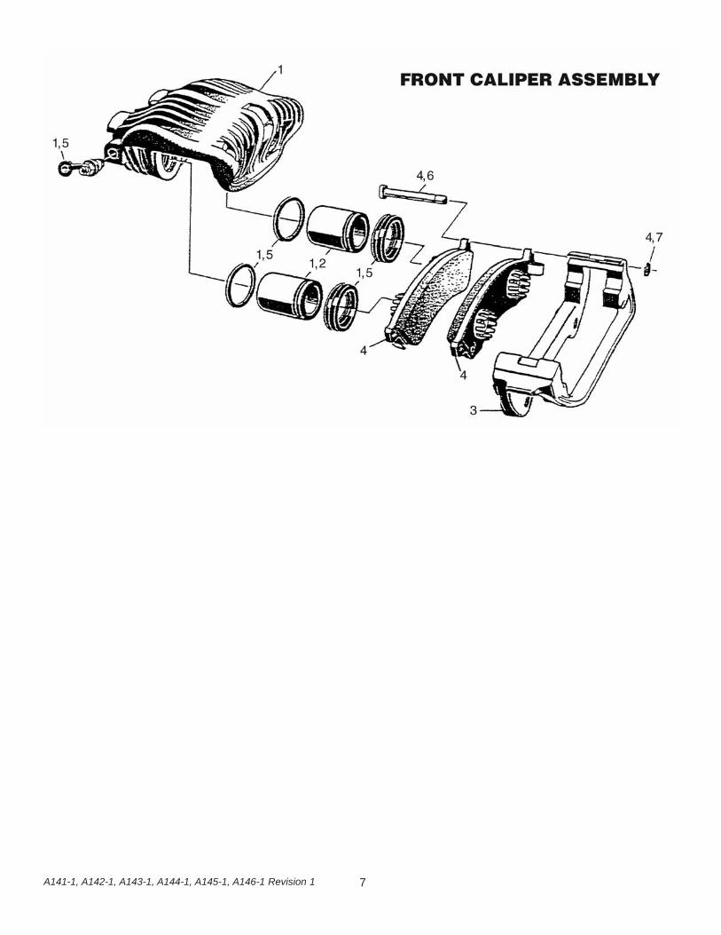
8) Installation of brake calipersa) Calipers are sent as complete assemblies with pads already installed (Figure 1). Make
sure to select correct caliper so bleeder screw is facing up. Slide caliper over rotor and line up holes in caliper bracket with those in the spindle. Using the 14mm bolts supplied in the kit, bolt bracket to spindle and torque to 90ft-lbs.
b) Attach the new flex line to caliper using banjo bolt and 1 new copper washer on either side of the end of the hose. Torque banjo bolt to 20 ft-lbs. Attach the other end of the flex hoses to the rigid line on the chassis.
c) With all hardware bolted on, turn wheels� lock to lock making sure there is nointerference or twisting of flexible brake hose.
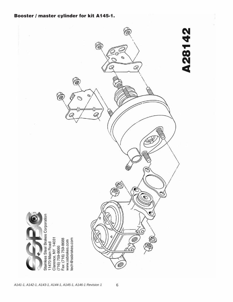
9) Installation of Booster and Master Assembly.a) If you have ordered the non-power kit, the master cylinder will bolt directly in place of
the drum brake master and the stock pushrod can be reused. If your car was originallypower drum and you are converting to non-power disc, you will need a non-power pushrod. This can be purchased from many aftermarket suppliers or obtained from a parts car.
2A141-1, A142-1, A143-1, A144-1, A145-1, A146-1 Revision 1

b) If you have ordered the power conversion kit, the booster and master cylinder are shipped assembled. For ease of installation and to allow for bench bleeding of the master cylinder, remove the master cylinder from the booster.
c) Install the jam-nut and clevis on the booster pushrod and set the booster in place on the four studs on the firewall. With the booster in place, secure the booster to the firewall with the four nuts and connect the clevis to the lower hole in the brake pedal.
d) The booster must be connected to a source of engine vacuum. The most convenient source for this is at the intake manifold. The hose used to connect this to the booster must be rated for vacuum service and have an outside diameter of no less than 11/32�.
NOTE: FOR PROPER BOOSTER OPERATION, THE ENGINE MUST DEVELOPNO LESS THAN 16� HG OF VACUUM AT IDLE.
e) The master cylinder MUST be bench bled prior to installation. See the attached page for proper bench bleeding procedures.
f) With the master cylinder bench bled, It can be installed on the booster cylinder and secured in place using the two nuts supplied with the booster.
g) There are three pieces of steel brake line provided with the kit. These lines have the correct oversize fittings for connection to the master cylinder and distribution block. Depending on the location of the factory distribution block and the way you choose to route your lines, you may or may not use these lines. If you choose to make up your own lines, be sure to reuse the fittings from the lines we supply to insure properinstallation.
IF YOU CHOOSE TO MAKE YOUR OWN LINES, KEEP THESE POINTS IN MIND:A. THE FRONT PORT OF THE MASTER CYLINDER SERVICES THE FRONT BRAKES.B. THE REAR PORT OF THE MASTER CYLINDER SERVICES THE REAR BRAKES.C. THE ADJUSTABLE PROPORTIONING VALVE CAN BE INSTALLED ANYWHERE IN THE FRONT TO REAR BRAKE LINE AS LONG AS IT�S AFTER THE FACTORY DISTRIBUTION BLOCK AND BEFORE THE REAR FLEX HOSE.D. REFER TO THE PROPORTIONING VALVE INSTRUCTIONS FOR PROPER ADJUSTMENT AND INSTALLATION.
10) Filling and Bleeding systema) It is advisable to replace the brake fluid if the color is brown or muddy. This is due to
water that has been absorbed by the fluid which will eventually corrode the brake lines and master cylinder. This absorbed moisture can also cause a vapor lock situation under extreme braking conditions. Flush system with clean brake fluid and replace with a good grade of disc brake fluid. DOT 3 or DOT 4 fluids are acceptable as well asDOT 5 if entire system is being changed.
b) The simplest and most effective way to bleed your brakes is to use the gravity bleedingapproach as follows:1) With calipers installed, make sure all fittings are tight and master cylinder is
topped off with fluid.2) Open one bleeder screw at a time starting at the wheel farthest from the master
cylinder and working your way back around the wheel closest to the master.
3A141-1, A142-1, A143-1, A144-1, A145-1, A146-1 Revision 1
With bleeder screw open, observe bleeder. At first the fluid will begin to escape with intermittent air bubbles. When the air bubbles stop and a steady flow of fluid is observed for several seconds, close the bleeder valve and move on to the next wheel.
MAKE SURE TO KEEP A CLOSE WATCH OVER THE FLUID LEVEL INSIDETHE MASTER CYLINDER DURING THE BLEEDING PROCESS. NEVER LETTHE RESERVOIR RUN DRY. ALWAYS KEEP IT AT LEAST 1/3 FULL.
3) After bleeding all four wheels and topping of the master cylinder, make 20-30 applications of the brake pedal. If a hard petal is experienced, no further bleeding is required. If pedal is spongy, repeat bleeding process until a hard pedal is achieved.
NOTE: BRAKE PEDAL END PLAY SHOULD BE 1/2� TO 3/4�. END PLAY CAN BEADJUSTED BY CHANGING THE LENGTH OF THE PUSHROD AT THE CLEVIS.
FINAL INSPECTION11) Once a hard pedal is achieved, all fittings and connections must be inspected to make sure
there are no leaks. Also check the level in both reservoirs of the master cylinder and top off, if needed.
12) Put wheels back on the car and turn wheel by hand to insure that the wheel spins freely and does not interfere with any brake components. If any interferences are detected, DO NOT drive vehicle until problem can be identified and corrected.
DO NOT DRIVE IN TRAFFIC UNTIL THE BRAKES SAFELY STOP THE CAR A SAFEDISTANCE WITHOUT A SPONGY PEDAL FEEL! BRAKING TESTS SHOULD ALWAYS BE
DONE IN A SAFE OPEN AREA!
TECH LINE -- If technical help is required, please call 716-759-8666.
NOW ENJOY TRUE PERFORMANCE BRAKING!
4A141-1, A142-1, A143-1, A144-1, A145-1, A146-1 Revision 1
5A141-1, A142-1, A143-1, A144-1, A145-1, A146-1 Revision 1
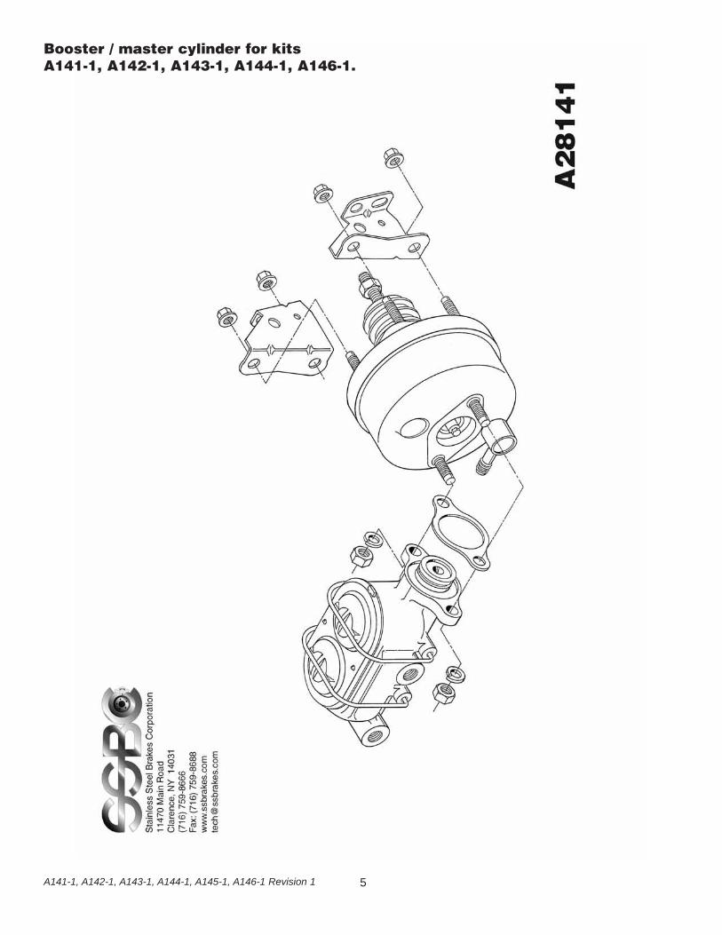
Booster / master cylinder for kits A141-1, A142-1, A143-1, A144-1, A146-1.
6A141-1, A142-1, A143-1, A144-1, A145-1, A146-1 Revision 1
Booster / master cylinder for kit A145-1.
7A141-1, A142-1, A143-1, A144-1, A145-1, A146-1 Revision 1

Solutions Guide Revision 5 716-759-8666 • [email protected]
How do you bench bleed a MasterCylinder?
Secure one of the ears in a vise so that you can take alarge screwdriver and push the piston in. Fill thereservoir with clean fluid. Take a dummy line or our M/Cbleeding kit and hook it up to the two ports. Front line tofront and rear line to rear reservoirs. Slowly stroke themaster and let it return slowly. You should see many airbubbles in the fluid. Repeat this step until you do notsee any more air bubbles. SSBC recommends ten (10)slow pumping strokes after you see no more airbubbles. This will insure a good hard pedal. (See SSBCpart #0460 Instruction Sheet)
What is the best pad for my vehicle?
Your choice of pads should be determined by how andwhere you drive the vehicle. If you drive in heavy stopand go traffic you would need a different pad thansomeone who is road racing. Contact SSBC for thecorrect application.
How often should brake fluid bechanged? (street application only,not racing)
When brake fluid turns brown, it is time to change thefluid. The brown color indicates that the fluid hasabsorbed water and dirt. D.O.T. #3 & #4 fluids absorbwater. Silicone brake fluid is not for track racing.
How can I tell which reservoir is thefront or rear of the Master Cylinder?
The front reservoir is usually larger than the rear. Insome cases, they are the same size. As a rule, for GMcars & trucks, the rear reservoir is for the rear brakes.On Ford cars & trucks, the front reservoir is for the rearbrakes. On front wheel drive vehicles, the brakes aresplit diagonally. Each bowl of the master cylinderservices one front wheel and one rear wheel. This willbe important if you are installing a distribution block,proportioning valve, or residual valve. Hint: The largerbowl will feed the disc brakes.
1
Why is my brake pedal soft?
1) In most cases, Air is trapped in the lines or calipers.Try re-bleeding the system. Do not force new fluid intonew brake lines. It may foam and be very difficult tobleed. Make sure that the bleeder screws on thecalipers are facing upward!
2) If all the air is out of the system, the pushrod fromthe booster may need adjustment, under the dash, tomake it longer. Do not extend it too long or it will notallow the fluid to return, causing brakes to drag. Yourpushrod may not be adjustable. If the pushrod can bemade longer, try ¼ turn adjustments at a time. SSBCstocks adjustable pushrods for many vehicles. Inaddition, the pushrod between the Booster and theMaster Cylinder may need adjustment. Not all Boosterto Master pushrods are adjustable.
3) You may have a bad Master Cylinder. Before youdetermine this, you should make sure that all the air isout of the system. When installing a new MasterCylinder, always bench bleed first. If you did not, takeoff the Master Cylinder and bench bleed it. (See BenchBleeding Instructions below)
Why does the car pull to one side?
The side that the car is pulling to is the caliper that isworking. Re-bleed the opposite side and try carefullystopping again.
Why does it feel like there is noPower Assist?
The Booster may not be getting enough vacuum tooperate. On some high lift cams, the engine does notdevelop enough vacuum. The Booster needs at least16” of vacuum to operate correctly at idle. If you do nothave at least 16 inches of vacuum at idle, you may haveto add a vacuum pump to your system.Check for vacuum leaks. There may be leaks in theintake manifold or hoses that would cause low vacuum.The Booster may be bad. Do a vacuum test. If theBooster can retain a vacuum for three (3) minutes afterthe vehicle is shut off, it is not a bad Booster (refer tosteps 1 & 2). All Master Cylinders must be bench bledin a vise before being installed on the vehicle.
Solutions Guideto commonly asked questions.
Solutions Guide Revision 5 716-759-8666 • [email protected]
Where is the best place to install aproportioning valve?
The best place to install a proportioning valve is afterthe distribution block. Do Not install it between theDistribution Bock and the Master Cylinder. You willnot be able to get a hard pedal. Anywhere after theDistribution Block and before the rear flex hose isacceptable for installation.
Why should the flex hoses bereplaced? They look O.K. from theoutside.
Flex hoses should be replaced every time the calipersare serviced. They flex up and down, just like a shockabsorber. They are also under high pressure internally.Flex hoses have a rubber liner that will collapse overtime. If it does collapse, it will act as a check valve andnot allow fluid to return to the Master Cylinder.
Will my pedal get harder by replacingthe flex hoses?
No. When the flex hoses are replaced, re-bleed thebrake system. Normally what happens is that bleedingcauses a harder brake pedal. A better bleeding job andtaking your time will result in the same situation.
Are the rubber flex hoses expandingcausing a soft pedal?
Not likely. A soft pedal is usually a sign of air in thesystem due to poor bleeding. Flex hoses have nylonwebbing that is molded into the internal rubber. It is verystrong and will hold up to 3,000 P.S.I. Installing braidedstainless steel hoses is not necessary; it only improvesappearance.
How much brake pressure does ittake to stop my vehicle?
Most vehicles, power or non power brake, develop1,200 P.S.I. When you panic stop or jump on the brakeshard, a surge of 1,400 P.S.I. can be achieved. If afactory proportioning valve installed on the vehicle, therear brakes are only developing 600 – 700 P.S.I. Drumbrakes require lower pressure because they grab morequickly. When rear disc brakes are installed, the rearbrake pressure may be increased to 800 – 1,000 P.S.I.or more. A good way to check the pressures and to seeif the system is working correctly, use a pressure gaugescrewed into the bleeder port (SSBC part # A1704). Avehicle with less than 600 P.S.I will not stop!
How tight should the wheel bearingsbe?
The front bearings should always be torqued. Not justhand tightened. Bearings usually require 12-15 Ft./Lbs.of torque. Then you will probably need to back off a littleto align the cotter pin hole. Do Not over tighten; thebearing life will be shortened. This procedure onlyapplies to rear wheel drive vehicles with separatebearings and races. On vehicles with one piece sealedbearing assemblies or hub assemblies, refer to aservice manual.
What type of differential fluid shouldI use in my rear axle?
If you have positraction, use a Hypoid or Limited Slipadditive that is designed for your particular rear end. Ifyou do not have positraction, any type of 80 –90 weightgear lube is acceptable. Fluid should be changed oftenif you are trailering or any type of extreme usage. Thisfluid does brake down with time and usage.

3Solutions Guide Revision 5 716-759-8666 • [email protected]
Replacement Pads for SSBC Performance Brake Kits
*RE-ORDER PADS DIRECTLY FROM SSBC
A109A109-1A109AFA109ARA109SA110A110-10A110-11A110-12A110-13A110-14A110-15A110-16A110-17A110-18A110-19A110-2A110-3A110-4A110-5A110-6A110-7A110-8A110-9A111A111-10A111-11A111-12A111-13A111-14A111-15A111-16A111-17A111-18A111-19A111-2A111-20A111-21A111-22A111-23A111-24A111-25A111-26A111-27A111-28A111-29A111-3A111-30A111-31A111-32A111-33A111-4A111-5A111-6A111-7A111-8A111-9A112A112-1A112-11A112-12A112-13A112-14A112-15A112-16A112-17
A112-2A112-3A112-4A112-5A112-6A112-7A112-8A112-9A112-93A113A113-1A113-10A113-11A113-12A113-4A113-5A113-6A113-7A113-8A113-9A114A115A116A117A117-1A117-10A117-11A117-12A117-13A117-14A117-15A117-2A117-3A117-4A117-5A117-6A117-7A117-8A117-9A118A120A120-10A120-11A120-12A120-2A120-2PA120-2POA120-2PPOA120-3A120-4A120-5A120-6A120-7A120-7AA120-7MA120-8A120-9A120DA120PA121A121-2PA121-2PAA121-2PAPOA121-2PMA121-2PMPOA121P
A121P-AA121P-MA123A123-1A123-13A123-14A123-15A123-16A123-17A123-18A123-1AA123-1CA123-2A123-3A123-3AA123-4A123-4AA123-5A123-58A123-58AA123-59A123-59AA123-5AA123-6A123-67A123-68A123-69A123-6AA123-7A123-8A123-9A123-AA124A125A125-1A125-10A125-11A125-12A125-13A125-14A125-15A125-16A125-17A125-18A125-19A125-1FA125-2A125-20A125-21A125-22A125-23A125-24A125-25A125-26A125-27A125-28A125-29A125-3A125-30A125-31A125-32A125-33A125-34A125-35A125-36A125-4
A125-5A125-6A125-7A125-8A125-9A125-FA125PA126A126-1A126-10A126-11A126-12A126-13A126-14A126-15A126-16A126-17A126-18A126-19A126-2A126-20A126-21A126-22A126-23A126-24A126-25A126-26A126-27A126-28A126-29A126-3A126-30A126-31A126-32A126-33A126-34A126-35A126-37A126-38A126-39A126-4A126-40A126-41A126-46A126-5A126-51A126-6A126-61A126-7A126-71A126-71AA126-7AA126-8A126-9A127A127-1A127-2A127-3A127-4A127-5A127-6A127-7A127-8A127-9A128A128-1
101210108101281012810121049101291011310113101510135109510128101281047101131047101281012810151015101101011010129104910151015101101011010110101101012910129101291012910471011310113101131011310151013510951012810151012910135109510128101281012810128101281012810128A1015-3101510471047109510951011310471047109510133-1
1047107110471061-11012810711012810151047107110711071101510951012810151012810128107010128104710471049104710471011310951095101131011310113104710711071101281012810128104710951049A103310128101281012810110101101012910129101281014410144101281012810128101281012810128A1033A1033A103310110101101011010110A10129A1033
A1033A103310501050109510951011610116109510951015105010711050101510501015105010501015105010151015107110711071107110711012810128101281015104710471047101281012810128101281015101510151015101101011010471047101101012810129101291012910129101131011310113101131047101131015101510135109510128101281047
1047104710471012810128104710471070P10471015101510151094A1094A1094A1094A1094A10151094A10471015101291012810128101281012810128101281012810128A1094B10128101281015101281012810128109510951095A1094B101261012610126104710471050105010941094A1094A109410941049104710128107010711012810128101510471015104710471047
D-8D-531D-531D-531D-8D-204D-43D-154D-154D-52D-137D-731D-531D-531D-347D-154D-347D-531D-531D-52D-52D-11D-11D-43D-204D-52D-52D-11D-11D-11D-11D-43D-43D-43D-43D-347D-154D-154D-154D-154D-52D-137D-731D-531D-52D-43D-137D-731D-531D-531D-531D-531D-531D-531D-531*D-52D-347D-347D-731D-731D-154D-347D-347D-731D-784
D-347D-347D-347D-531D-531D-347D-347D-413D-347D-52D-52D-52D-370D-370D-370D-370D-370D-52D-370D-347D-52D-43D-531D-531D-531D-531D-531D-531D-531D-531*D-531D-531D-52D-531D-531D-531D-731D-731D-731*D-834D-834D-834D-347D-347D-52D-52D-369D-369**D-369D-204D-347D-531D-413D-412D-531D-531D-52D-347D-52D-347D-347D-347
**D-52D-52D-731D-731D-749D-749D-731D-731D-52D-52D-412D-52D-52D-52D-52D-52D-52D-52D-52D-52D-52D-412D-412D-412D-412D-412D-531D-531D-531D-52D-347D-347D-347D-531D-531D-531D-531D-52D-52D-52D-52D-11D-11D-347D-347D-11D-531D-43D-43D-43D-43D-154D-154D-154D-154D-347D-154D-52D-52D-137D-731D-531D-531D-347
D-347D-412D-347D199D-531D-412D-531D-52D-347D-412D-412D-412D-52D-731D-531D-52D-531D-531D-413D-531D-347D-347D-204D-347D-347D-154D-731D-731D-154D-154D-154D-347D-412D-412D-531D-531D-531D-347D-731D-204*D-531D-531D-531D-11D-11D-43D-43D-531D-289D-289D-531D-531D-531D-531D-531D-531***D-11D-11D-11D-11**
SSBC SSBCKit # Pad # FMSI #
SSBC SSBCKit # Pad # FMSI #
SSBC SSBCKit # Pad # FMSI #
SSBC SSBCKit # Pad # FMSI #
4Solutions Guide Revision 5 716-759-8666 • [email protected]
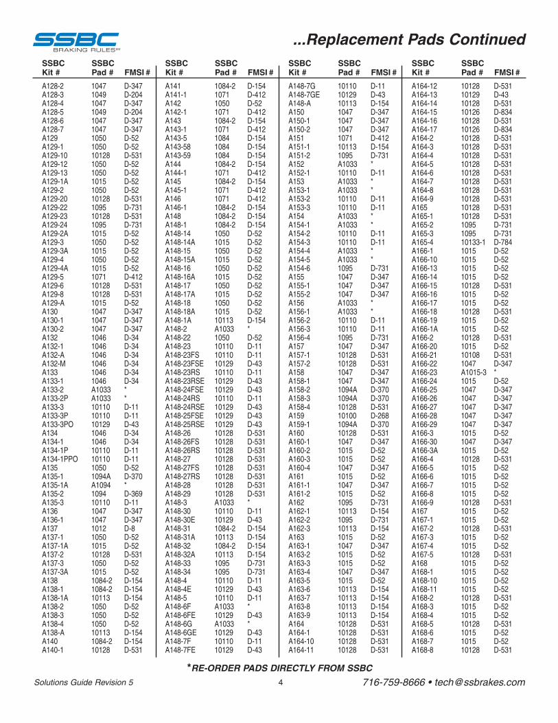
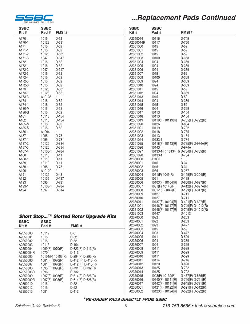
...Replacement Pads Continued
*RE-ORDER PADS DIRECTLY FROM SSBC
A128-2A128-3A128-4A128-5A128-6A128-7A129A129-1A129-10A129-12A129-13A129-1AA129-2A129-20A129-22A129-23A129-24A129-2AA129-3A129-3AA129-4A129-4AA129-5A129-6A129-8A129-AA130A130-1A130-2A132A132-1A132-AA132-MA133A133-1A133-2A133-2PA133-3A133-3PA133-3POA134A134-1A134-1PA134-1PPOA135A135-1A135-1AA135-2A135-3A136A136-1A137A137-1A137-1AA137-2A137-3A137-3AA138A138-1A138-1AA138-2A138-3A138-4A138-AA140A140-1
A141A141-1A142A142-1A143A143-1A143-5A143-58A143-59A144A144-1A145A145-1A146A146-1A148A148-1A148-14A148-14AA148-15A148-15AA148-16A148-16AA148-17A148-17AA148-18A148-18AA148-1AA148-2A148-22A148-23A148-23FSA148-23FSEA148-23RSA148-23RSEA148-24FSEA148-24RSA148-24RSEA148-25FSEA148-25RSEA148-26A148-26FSA148-26RSA148-27A148-27FSA148-27RSA148-28A148-29A148-3A148-30A148-30EA148-31A148-31AA148-32A148-32AA148-33A148-34A148-4A148-4EA148-5A148-6FA148-6FEA148-6GA148-6GEA148-7FA148-7FE
A148-7GA148-7GEA148-AA150A150-1A150-2A151A151-1A151-2A152A152-1A153A153-1A153-2A153-3A154A154-1A154-2A154-3A154-4A154-5A154-6A155A155-1A155-2A156A156-1A156-2A156-3A156-4A157A157-1A157-2A158A158-1A158-2A158-3A158-4A159A159-1A160A160-1A160-2A160-3A160-4A161A161-1A161-2A162A162-1A162-2A162-3A163A163-1A163-2A163-3A163-4A163-5A163-6A163-7A163-8A163-9A164A164-1A164-10A164-11
A164-12A164-13A164-14A164-15A164-16A164-17A164-2A164-3A164-4A164-5A164-6A164-7A164-8A164-9A165A165-1A165-2A165-3A165-4A166-1A166-10A166-13A166-14A166-15A166-16A166-17A166-18A166-19A166-1AA166-2A166-20A166-21A166-22A166-23A166-24A166-25A166-26A166-27A166-28A166-29A166-3A166-30A166-3AA166-4A166-5A166-6A166-7A166-8A166-9A167A167-1A167-2A167-3A167-4A167-5A168A168-1A168-10A168-11A168-2A168-3A168-4A168-5A168-6A168-7A168-8
1047104910471049104710471050105010128105010501015105010128109510128109510151050101510501015107110128101281015104710471047104610461046104610461046A1033A103310110101101012910461046101101011010501094AA10941094101101047104710121050101510128105010151084-21084-210113105010501050101131084-210128
1084-21071105010711084-210711084108410841084-210711084-2107110711084-21084-21084-2105010151050101510501015105010151050101510113A10331050101101011010129101101012910129101101012910129101291012810128101281012810128101281012810128A103310110101291084-2101131084-21011310951095101101012910110A103310129A1033101291011010129
1011010129101131047104710471071101131095A103310110A1033A10331011010110A1033A10331011010110A1033A10331095104710471047A1033A10331011010110109510471012810128104710471094A1094A10128101001094A1012810471015101510471015104710151095101131095101131015104710151015104710151011310113101131011310128101281012810128
101281012910128101261012810126101281012810128101281012810128101281012810128101281095109510133-1101510151015101510128101510151012810151015101281015101081047A1015-3101510471047104710471047101510471015101281015101510151015101281015101510128101510151012810151015101510151012810151015101281015101510128
D-347D-204D-347D-204D-347D-347D-52D-52D-531D-52D-52D-52D-52D-531D-731D-531D-731D-52D-52D-52D-52D-52D-412D-531D-531D-52D-347D-347D-347D-34D-34D-34D-34D-34D-34**D-11D-11D-43D-34D-34D-11D-11D-52D-370*D-369D-11D-347D-347D-8D-52D-52D-531D-52D-52D-154D-154D-154D-52D-52D-52D-154D-154D-531
D-531D-43D-531D-834D-531D-834D-531D-531D-531D-531D-531D-531D-531D-531D-531D-531D-731D-731D-784D-52D-52D-52D-52D-531D-52D-52D-531D-52D-52D-531D-52D-531D-347*D-52D-347D-347D-347D-347D-347D-52D-347D-52D-531D-52D-52D-52D-52D-531D-52D-52D-531D-52D-52D-531D-52D-52D-52D-52D-531D-52D-52D-531D-52D-52D-531
D-11D-43D-154D-347D-347D-347D-412D-154D-731*D-11**D-11D-11**D-11D-11**D-731D-347D-347D-347**D-11D-11D-731D-347D-531D-531D-347D-347D-370D-370D-531D-268D-370D-531D-347D-52D-52D-347D-52D-347D-52D-731D-154D-731D-154D-52D-347D-52D-52D-347D-52D-154D-154D-154D-154D-531D-531D-531D-531
D-154D-412D-52D-412D-154D-412D-154D-154D-154D-154D-412D-154D-412D-412D-154D-154D-154D-52D-52D-52D-52D-52D-52D-52D-52D-52D-52D-154*D-52D-11D-11D-43D-11D-43D-43D-11D-43D-43D-43D-531D-531D-531D-531D-531D-531D-531D-531*D-11D-43D-154D-154D-154D-154D-731D-731D-11D-43D-11*D-43*D-43D-11D-43
SSBC SSBCKit # Pad # FMSI #
SSBC SSBCKit # Pad # FMSI #
SSBC SSBCKit # Pad # FMSI #
SSBC SSBCKit # Pad # FMSI #
5Solutions Guide Revision 5 716-759-8666 • [email protected]
...Replacement Pads Continued
*RE-ORDER PADS DIRECTLY FROM SSBC
A170A170-1A171A171-1A171-2A171-3A172A172-1A172-2A172-3A172-4A172-5A172-6A173A173-1A173-3A174A174-1A180-MA180-SA181A182A185-MA185-SA186-1A187A187-1A187-2A187-3A187-4A188A188-1A189A189-1A190A191A192A193A193-1A194
A2350014A2350014RA2351000A2351001A2351002A2351003A2351004A2351005A2351006A2351007A2351008A2351009A2351010A2351011A2351012A2351013A2351014A2351015A2351016A2351017A2351018A2351019A2351020A2351021A2351022A2351023A2351024A2351025A2351026A2351027A2351028A2360000A2360001A2360002A2360003A2360004A2360005A2360006A2360007A2360008A2360009A2360010A2360011A2361001A2361002A2361003A2370000A2370001A2370002A2370003A2370004A2370005A2370006A2370007A2370008A2370009A2370010A2370011A2370012A2370013A2370014A2370015A2370016A2370017A2380001A2380002
1015101281015101510128104710151015104710151015101510151012810128A101351015101510151015101131011310151015A109410951095101261012610133-11011010110101101095A101291012910135109510133-11097
10116101171015101510151010010941094109410151010010941094101510941015109410151094101131011310118(F) 10119(R)1012610119101181011310133-110118(F) 10143(R)1014310133-1(F) 10134(R)10133-1A10331046104610661061(F) 1049(R)106110103(F) 10104(R)1081(F) 10145(R)1061-1(F) 1047(R)101271012710137(F) 10104(R)10146(F) 10147(R)10146(F) 10147(R)10147109210921093101510931011110941094101111011110111101141012010125101251093(F) 10139(R)10140(F) 10141(R)10142(F) 10141(R)10121(F) 10122(R)10123(F) 10124(R)
D-52D-531D-52D-52D-531D-347D-52D-52D-347D-52D-52D-52D-52D-531D-531*D-52D-52D-52D-52D-154D-154D-52D-52*D-731D-731D-834D-834D-784D-11D-11D-11D-731*D-43D-137D-731D-784D-614
D-749D-750D-52D-52D-52D-368D-369D-369D-369D-52D-368D-369D-369D-52D-369D-52D-369D-52D-369D-154D-154D-785(F) D-792(R)D-834D-792D-785D-154D-784D-785(F) D-974A(R)D-974AD-784(F) D-785(R)D-784*D-34D-34D-237D-199(F) D-204(R)D-199D-600(F) D-627(R)D-412(F) D-627A(R)D-199(F) D-347(R)D-711D-711D-491(F) D-627(R)D-749(F) D-1012(R)D-749(F) D-1012(R)D-1012D-203D-203D-477D-52D-477D-529D-369D-369D-529D-529D-529D-746D-820D-702D-702D-477(F) D-666(R)D-790(F) D-791(R)D-945(F) D-791(R)D-591(F) D-512(R)D-592(F) D-592(R)
SSBC SSBCKit # Pad # FMSI #
Short Stop...™ Slotted Rotor Upgrade KitsSSBC SSBCKit # Pad # FMSI #
A2350000A2350001A2350002A2350003A2350004A2350004RA2350005A2350006A2350007A2350008A2350008RA2350009A2350009RA2350010A2350012A2350013
1011210151015101131099(F) 1070(R)107010101(F) 10102(R)1081(F) 1070(R)1081(F) 1070(R)1095(F) 1096(R)10961097(F) 1098(R)1097(F) 1098(R)101510151081
D-8D-52D-52D-154D-623(F) D-413(R)D-413D-294(F) D-295(R)D-412 (F) D-413(R)D-412 (F) D-413(R)D-731(F) D-732(R)D-732D-614(F) D-628(R)D-614(F) D-628(R)D-52D-52D-412
SSBC SSBCKit # Pad # FMSI #

Solutions Guide Revision 5 716-759-8666 • [email protected]
REPLACEMENT
PARTS
ORDER FORM
DATE: __________________________ CUSTOMER # (from receipt): ____________
ORDERED BY:NAME: _______________________________
COMPANY: ____________________________
STREET: ______________________________
CITY: ___________ ST: ____ ZIP: _________
DAY PHONE: ___________________________
FAX: _________________________________
E-MAIL: ______________________________
SHIP TO:NAME: _______________________________
COMPANY: ____________________________
STREET: ______________________________
CITY: ___________ ST: ____ ZIP: _________
DAY PHONE: ___________________________
FAX: _________________________________
E-MAIL: ______________________________
VEHICLE INFORMATION:TYPE OF AUTOMOBILE: _________________________
YEAR ______ ENGINE: __ 4 CYL. __ 6 CYL. __ 8 CYL.
TYPE OF DRIVING:__ STREET __ RACING
__ STREET & SLALOM __ STREET MODIFIED
QUANTITY PART # DESCRIPTION UNIT PRICE AMOUNT
METHOD OF PAYMENT:__ CHECK/MONEY ORDER __ VISA __ MASTERCARD __ DISCOVER __ AMEX
CREDIT CARD #: _____________________________ EXP: _____________
SIGNATURE: ___________________________________________________
Price subject to change without notice. Not responsible for typographical errors.
NOTE: Name, address & telephone number must be printed on checks. Driver’s License numberrequired for personal checks.
Total Merchandise
NY Residents Sales Tax
Ins. (add $0.35 per $100.00)
UPS Shipping (please call)
TOTAL
FREE FREIGHTIF ORDERED WITHIN 30 DAYS OF INITIAL ORDER
MAIL OR FAX YOUR ORDER!
ORDER INFORMATION:
6
Stainless Steel Brakes Corporation11470 Main Road • Clarence, NY 14031Ph: 716-759-8666 Fx: 716-759-8688ssbrakes.com • [email protected]

7Solutions Guide Revision 5 716-759-8666 • [email protected]
How and why do I bench bleed a master cylinder?
When installing or replacing a master cylinder, it is critical that allair is removed from the master cylinder. This can easily be doneby bench bleeding the master cylinder prior to installation. Usingthe SSBC master cylinder bleeder kit (#0460):
1) Place your master cylinder in a vise by the ears (not body).Make sure it is level.
2) Attach a piece of clear plastic hose to the short end of one ofthe plastic nozzles. Do the same to the other hose andnozzle.
3) Clip the plastic bridge to the wall and push the ends of thehose through the holes so they are SUBMERGED in the reservoir on either side of the wall.
4) Press the tapered end of the nozzle FIRMLY into the cylinder port hole with a twisting motion. Repeat thisprocedure on the other port hole.
5) Fill the reservoir with CLEAN brake fluid recommended by the manufacturer.6) Using full strokes, push the piston in, then release. Do this until ALL the air bubbles have disappeared
from the clear plastic hose. (CAUTION-MASTER CYLINDER WILL NOT BLEED PROPERLY UNLESSHOSES ARE SUBMERGED IN BRAKE FLUID UNTIL THE BLEEDING PROCESS IS COMPLETED.)
Now mount master cylinder and avoid brake fluid leaking out of front and rear ports during installation.
Bleeding steps for Dual Port Master Cylinder
If you have a master cylinder with dual port holes (4 port holes - 2 on each side), it is necessary to bleed bothport sides of the master cylinder. If both sides of the master cylinder are not bled, there will be air trapped inthe master cylinder and your brakes will not function properly.
To bleed dual port master cylinders:
1) Follow steps 1 - 6 above on the side you will be hooking the brake lines to. Plug the other side.2) Once the air bubbles are no longer visible in the plastic hose, open the bleeder screws in the supplied
plugs and allow the mater cylinder to gravity bleed. DO NOT push the master cylinder piston in while theplugs are gravity bleeding.
3) When clear, steady streams of fluid are coming out of both bleeders, close and tighten the bleeders. Givethe master cylinder piston several strokes, making sure there are still no bubbles present in the clearplastic tubes.
4) Remove the tubes and plastic fittings and mount the master cylinder on the vehicle being careful not tospill brake fluid on any painted surfaces.

8Solutions Guide Revision 5 716-759-8666 • [email protected]
TORQUE SPECIFICATIONSBEFORE DRIVING YOURVEHICLE, YOU SHOULDCHECK THE TORQUE ON ALLNUTS AND BOLTS IN THE KIT,INCLUDING ANY SLIDERBOLTS ON THE CALIPERS.RE-TORQUE CALIPER BOLTSAFTER 500 MILES. ALLSPECIFICATIONS ARE IN FT-LBS.
SAE 2 SAE 7 SAE 8SAE 5
5.8 9.8 10.98.8
LowCarbon(soft)
MediumCarbon Alloy
MediumCarbonHeat Treat
MediumCarbonAlloy
U.S.
SteelType
Metric
BOLT GRADES
1/4” 20 4 3 8 6 10 8 12 9 14 111/4” 28 6 4 10 7 12 9 14 10 16 135/16” 18 9 7 17 13 21 16 25 18 29 235/16” 24 12 9 19 14 24 18 29 20 33 263/8” 16 16 12 30 23 40 30 45 35 49 393/8” 24 22 16 35 25 45 35 50 40 54 447/16” 14 24 17 50 35 60 45 70 55 76 617/16” 20 34 26 55 40 70 50 80 60 85 681/2” 13 38 31 75 55 95 70 110 80 113 901/2” 20 52 42 90 65 100 80 120 90 126 1009/16” 12 52 42 110 80 135 100 150 110 163 1309/16” 18 71 57 120 90 150 110 170 130 181 1445/8” 11 98 78 150 110 140 140 220 170 230 1845/8” 18 115 93 180 130 210 160 240 180 255 2043/4” 10 157 121 260 200 320 240 380 280 400 3203/4” 16 180 133 300 220 360 280 420 320 440 3507/8” 9 210 160 430 320 520 400 600 460 640 5107/8” 14 230 177 470 360 580 440 660 500 700 5601” 8 320 240 640 480 800 600 900 680 980 7801” 12 350 265 710 530 860 666 990 740 1060 845
Bolt Thread Dry Oiled Dry Oiled Dry Oiled Dry Oiled Dry OiledDia. per inch
SAE Bolt 2 2 5 5 7 7 8 8 Socket SocketGrade Head Head
Cap CapScrew Screw
5mm 3.5 5 6 86mm 6 9 10.5 128mm 15 22 25 3210mm 29 44 51 6212mm 51 76 89 111
Bolt Dia. Oiled Oiled Oiled Oiled
METRIC 5.8 8.8 9.8 10.9 Per SAE J1701 and SAE J1701M specifications.

9Solutions Guide Revision 5 716-759-8666 • [email protected]
UNIVERSAL FRONT DISC BRAKE CHECKLIST[ ] 1) Spindle Properly secured to ball joints and tie rods with castle nut and cotter pin.
[ ] 2) All mounting bolts properly tightened.
[ ] 3) Wheel bearings properly packed with grease.
[ ] 4) Inner bearing must be installed before grease seal.
[ ] 5) Rotor / bearings slide onto spindle with ease.
[ ] 6) Washer, castle nut properly torqued and cotter pin installed.
[ ] 7) Calipers installed and properly torqued.
[ ] 8) Spin rotor and check for any interference. (If any interference is found, resolve problembefore driving vehicle.)
[ ] 9) Flex lines are properly installed with no interference.
[ ] 10) Power booster (if applicable) installed properly.
[ ] 11) Master cylinder bench bled according to the instructions.
[ ] 12) All brake lines are properly tightened and free of leaks.
[ ] 13) Turn wheels lock to lock and check for any interference.
[ ] 14) Place wheel onto vehicle and spin the wheel to make sure there is no interferencebetween the brakes and wheel.
UNIVERSAL REAR DISC BRAKE CHECKLIST[ ] 1) All bolts on base bracket properly tightened.
[ ] 2) All caliper mounting bolts properly tightened.
[ ] 3) Rotor slides onto axle with ease.
[ ] 4) No interference with rotor and any other parts (splash shield, brackets, etc.).
[ ] 5) Caliper is centered over the rotor (because of difference in axle lengths, you may have toshim caliper in or out).
[ ] 6) No interference with caliper and rotor.
[ ] 7) All brake lines are tight with no leaks.
[ ] 8) Parking brake is properly adjusted and not dragging, with vehicle on ground.
[ ] 9) Adjustable proportioning valve installed (if applicable).
[ ] 10) Distribution block modification made (if applicable).
[ ] 11) Brake system properly bled.
WITH EVERY NEW SET OF ROTORS AND PADS, YOU SHOULD GIVE YOUR VEHICLE 200 - 250 MILES OF EASY DRIVING TO PROPERLY SEAT THE PADS TO THE ROTORS. DO NOT TAKE THE VEHICLE UP TO 60 MPH AND JAM ON THE BRAKES BEFORE THE FIRST 200 - 250 MILE BREAK IN PERIOD IS OVER, OR YOU WILL GLAZE THE PADS AND ROTORS.
Solutions Guide Revision 5 716-759-8666 • [email protected]
TECHNICAL SUPPORT / WARRANTY POLICY
You have just purchased a high quality product manufactured by Stainless Steel BrakesCorporation. To ensure proper installation, please read all instructions thoroughly beforebeginning your work. In most applications, your kit will install as the instructions indicate.From time to time, the original equipment on some vehicles may have slight variationsthat can effect the ease of installation. Minor modifications during installation may benecessary to successfully install your kit. If modifications are necessary, please refer toa licensed mechanic and/or contact our technicians for modification approval.
Installation of braking, steering and suspension components and systems require properprocedures and methods to assure safe and correct operations.
Always test completed installations in a safe area. For proper operation, and ifquestionable, correct prior to placing the vehicle in service.
Our company maintains experienced technical service personnel, including a licensedprofessional engineer who have the knowledge and background to help you withinstallation or operating problems. Our technicians may be reached by telephone at 716-759-8666, Monday - Friday, 9:30 AM - 5:30PM EST. If unavailable, please leave a briefmessage, including your day phone number, and they will return your call as soon aspossible. You can also e-mail us at [email protected]. If you prefer, we will be pleasedto speak with your installing mechanic.
If it becomes necessary to return an item for any reason, a Return Goods Authorization(RGA) Number must first be obtained by telephone. A simple written description of thereason for the return should be included with the part. Your name and phone numbershould also be included. (Use the attached form.) “Defective” is not enough of adescription. See following page for detailed instructions.
We urge you not to disassemble or alter any part supplied, nor purchase additional partsor services in order to facilitate installation. Lack of prior approval by our company willconstitute a violation of our warranty with consequent denial of reimbursement for parts -faulty or not.
Before contracting outside professional assistance, please be aware that we do notreimburse for labor charges under any circumstance. Consult our standard warranty cardprovided with your order.
Solutions Guide Revision 5 716-759-8666 • [email protected]
NEED TO RETURN A PART?FOLLOW THESE INSTRUCTIONS.
> Did you call our Technical Assistance (716-759-8666) before you decided to make areturn? If not, you should do so now.
> You must have a Return Goods Authorization Number (RGA) issued to you prior toreturning any item. If you return without an RGA #, you run the risk of not receivingcredit.
> Make sure to include the completed Return Form with invoice and RGA # with yourparts.
> Whenever possible, please return item in original box with invoice and RGA # clearlymarked on the outside of the box.
> Any return must be shipped postage paid - NO collect shipments will be accepted.
> All warranty items will be sent ground UPS. Any other type of shipping service will beat customer’s expense.
It is a good idea to insure the returned part(s) for the full value to protect yourself againstloss. We strongly suggest you ship by UPS or U.S. Mail, no BUS or AIR shipments willbe accepted. All foreign returns must have authorization.
NOTE: Under no circumstance should any product(s) or part(s) be returned withoutprior authorization number (RGA #). Any part which, in our opinion, showsevidence of being used, installed contrary to SSBC instruction, defaced,subjected to improper handling, packaging or shipping by the customer will notbe eligible for exchange, refund or warranty consideration.

Solutions Guide Revision 5 716-759-8666 • [email protected]
RETURN FORM
Name: _____________________________ Invoice #: _________________________
Address: ___________________________ Date Purchased: ____________________
___________________________________ Purchased From: ___________________
Phone: ____________________________
List item(s) and a detailed explanation of why you are returning the item(s):
__________________________________________________________________________________________________________________________________________________________________________________________________________________________________________________________________________________________________________________________________________________________________________________________________________________________________________________________________________________________________________________________________________________________________________________________________________________________________________________________________________________________________________________________________________________________
RGA # ____________________________
Use this label for your package.
From: ____________________________________________________________________________________
TO: Stainless Steel Brakes Corp.11470 Main RoadClarence, NY 14031
RGA #: ______________ Invoice #: _____________