Embed Size (px)
Citation preview

A Wirelessly Tunable Electrical Stimulator forionic Electroactive Polymers
Yi Huang, Student Member, IEEE, Daniel Browe, Joseph Freeman, and Laleh Najafizadeh, Senior Member, IEEE
Abstract— ionic electroactive polymers (iEAPs) respond toelectrical stimulation by changing in shape, caused by iondisplacement inside the polymer. Due to similarities between themechanism of action of iEAPs and the physiology of native muscletissue, iEAPs have great potentials in applications requiringskeletal muscle regeneration. This paper presents a new system-level solution for the realization of a tunable electrical stimulatorfor iEAPs, capable of remotely altering the degree and thedirection of the movement of iEAPs. Without using digitalmodulation schemes, the proposed stimulator uses frequencyat the primary side, to wirelessly tune the magnitude and thepolarity of the electric field generated at the secondary side,enabling remote stimulation of iEAPs. As a proof of concept, theproposed stimulator is implemented using custom-off-the-shelfcomponents. The performance of the stimulator is extensivelyevaluated under various conditions, including coil misalignment.The stimulator is also integrated with iEAP samples, and thefunctionality of the end-to-end module is examined based on theresponse and the movement characteristics of iEAPs in a series ofin vitro experiments. Results demonstrate the feasibility of usingthe proposed system as a reliable electrical stimulator for iEAPs.
Index Terms— Electrical stimulators, ionic electroactive poly-mers (iEAPs), actuation, implantable medical devices, wirelesspower transfer.
I. INTRODUCTION
Functional loss and impairment of skeletal muscle couldoccur as a result of a diverse range of causes including trauma,aging, and diseases such as amyotrophic lateral sclerosis[1], vascular disease, or cancer [2], [3]. Once a muscle isinjured, satellite cells are activated to help regenerate muscle[4]. However, satellite cell incidence in the tissue is ex-tremely low, and is dependent on the age and muscle fibercomposition [4]. Several approaches, such as intramuscularinjections of skeletal myoblasts [5], have been sought to aidin the regeneration of deteriorated tissue. However, existingsolutions display contractility only “after” new muscle hasbeen regenerated, which typically is a lengthy process. Theselimitations highlight the need for the development of newtechnologies that can provide function and regeneration of losttissue in a timely manner, to improve the patient’s quality oflife over both short and long terms.
A possible solution to these problems is envisioned to bemade by combining ionic electroactive polymers (iEAPs) [6]-[10] with their tunable electrical stimulators [3], [11], forming
Y. Huang and L. Najafizadeh are with the Department of Electrical andComputer Engineering, Rutgers University, Piscataway, NJ 08854, USA.Y. Huang is also with Intersil Corporation, Bridgewater, NJ 08807, USA,email: [email protected], [email protected]. D. Browe andJ. Freeman are with the Department of Biomedical Engineering, Rutgers Uni-versity, Piscataway, NJ 08854, USA, email: [email protected],[email protected]. Corresponding Author: Laleh Najafizadeh.
This work was supported by NSF under grant 1408202.
contractile scaffolds. The development of such a subcutaneousmodule with the ability to actuate at different levels, priorto tissue regeneration, will enable restoring muscle functionimmediately upon the loss of skeletal muscle. Furthermore,since mechanical stimulation facilitates the formation of newmuscle tissue by enhancing cellular proliferation [12], it isexpected that such a module will also speed up the process oftissue regeneration. Thereby, the technology has the potentialto significantly impact the quality of life of many people whodeal with problems related to loss of muscle function.
iEAPs respond to electrical stimulation by changing inshape that is caused by ion displacement inside the polymer[7], [10], [13]. The degree and the direction of contraction aredependent on the magnitude and the polarity of the electricfield supplied by the stimulator. As such, to achieve differentlevels of actuation after implanting the module in the body,both the magnitude and the polarity of the electric fieldmust be made wirelessly tunable. In this paper, we presenta new system-level solution for the design of a stimulatorthat enables the remote alteration of both the magnitude andthe polarity of the electric field required for actuating iEAPs,without using digital modulation schemes. In our previouswork [3], [14] we had demonstrated the concept of using alow dropout (LDO) regulator to provide electrical stimulationto iEAPs. In [11] we presented that frequency can be utilizedto generate tunable voltage magnitudes. However, only thevoltage magnitude was made remotely tunable. This paperpresents a complete system capable of wireless tuning ofboth the magnitude and the polarity of the voltage, thereby,accommodating the stimulation requirements of iEAPs. Tothe best of our knowledge, this is the first work that targetsdesigning a wirelessly tunable electrical stimulation systemfor iEAPs. While here we are targeting iEAPs, the proposedsystem can be also utilized in other biomedical applicationswhere tunable electrical stimulation is required.
The rest of the paper is organized as follows. In Section II,an overview of iEAPs and their actuation process is presented.Section III presents the system-level overview of the proposedtunable stimulator. As a proof of concept, the stimulatoris implemented using custom-off-the-shelf (COTS) products.Details of this implementation are provided in Section IV.Extensive experiments have been conducted to evaluate theperformance of the stimulator, and results are presented inSection V. To assess the capabilities of the proposed systemin serving as the electrical stimulator for iEAPs, in vitroexperiments have been performed and results are described inSection VI. In Section VII, future directions towards realizingan implantable module are discussed, and finally the paper isconcluded in Section VIII.

Fig. 1. Conceptual illustration of the operating mechanism of iEAPs insidean electric field (after [14]).
II. BIOCOMPATIBLE IONIC ELECTROACTIVE POLYMERS
iEAPs have the potential to be used as artificial muscles andas scaffolds for skeletal muscle tissue engineering, becausethere are parallels between the mechanism of action of iEAPsand the physiology of native muscle tissue. When iEAP gels(hydrogels) are exposed to an electric field, charged ionsdiffuse through the gel and cause actuation. Fig. 1 conceptuallyillustrates this action [14]. Inside the hydrogels, there existfixed partial negative charges that are attached to the poly-mer backbone. When swelled with phosphate buffered saline(PBS), positively-charged cations associate with the watermolecules via hydrogen bonds, and evenly disperse throughthe hydrogel. When an electric field is applied, the positively-charged cations and associated water molecules move towardsthe negative electrode, causing one side of the hydrogel toswell. The swelling results in an overall bending actuation inthe construct [15] (as seen in Fig. 1). This mechanism of actionis similar to muscle tissue, in which an external source ofdepolarization (nerve signal) leads to conformational changesand movement (contraction for muscle) [16].
iEAPs in this study were constructed using poly(ethyleneglycol) diacrylate (PEGDA, or PEG for short) and acrylicacid (AA). PEG is a biocompatible, hydrogel-forming poly-mer that is relatively biologically inert. Depending on theapplication, different polymers and moieties (e.g. poly(vinylalcohol) (PVA), poly(acrylic acid) (PAA)) can be used to formthe hydrogels, and different methods can be used to form thenetwork (e.g. freezing, cycling, heating) [14], [17], [18]. Weused AA monomers because they introduce a highly polarfunctional group, which can easily be tuned by changing theirrelative concentration.
The crosslinked copolymer of PAA and PEG was createdusing the reaction in which the chemistry of PEG was al-tered to make it more electroactive through the binding ofthe polar monomer AA [14]. In the fabrication process, aprepolymer solution containing AA monomer, PEGDA witha molecular weight of 4000 Daltons, and a photoinitia-tor solution (2,2-dimethoxy-2-phenyl acetophenone, n-vinyl-2-pyrrolidinone, 300 mg/mL) was exposed to long-wavelengthUV light (365 nm, 10 mW/cm2) for up to five minutes. Thephotoinitiator is converted into a free radical via cleavage andinitiates the polymerization of AA into PAA, simultaneouslyincorporating PEGDA via the acrylate groups as it progresses
Fig. 2. Block diagram of the proposed tunable electrical stimulator for iEAPs.
[14]. Since each C=C bond provides two reactive sites, randompolymerization and crosslinking of the PEG-PAA hydrogeloccurs once activated by the free radical. Following thesefabrication steps, the biocompatible PAA-PEG hydrogels candemonstrate reversible, repeatable actuation while supportingcell growth [14].
III. SYSTEM OVERVIEW
The proposed system is designed to enable wireless tuningof both the degree and the direction of the movement of iEAPs.The application does not require stimulating a large number ofsites to justify the incorporation of digital modulation schemescommonly used in implantable stimulators [19]- [24]. As such,in order to save on the area and the size of the implant, analternative solution is proposed here.
Fig. 2 shows the block diagram of the proposed stimulator,where the power unit is also included for wirelessly poweringup the circuits on the secondary side. To provide tunablestimulation, the proposed control unit uses the frequency onthe primary side as the tuning variable. This is motivatedby the fact that unlike the amplitude, the frequency of thesignal received at the secondary side is immune to attenuationand distortion that could be experienced across the inductivelink. The overall aim here is to design a system-level solutionthrough which both the polarity and the magnitude of theelectric field at the secondary side, can be changed by tuningthe frequency at the primary side. Note that the word “control”is used here to refer to the ability of the system to alter (ortune) the magnitude and the polarity of the output voltage.
To be able to tune both the polarity and the magnitude ofthe output voltage using the input frequency, it is proposed todivide the input frequency range into three regimes (see Fig. 3-b). The input frequencies corresponding to “Regime 1” will beused to generate output voltages with positive polarity, and theinput frequencies corresponding to “Regime 2” will be usedto generate output voltages with negative polarity. Therefore,the inductive link and the resonant circuitry at the control unitshould be designed such that a reasonably flat response isobtained across the frequency range considered for tuning.
In order to use the input frequency (fIN) as the tuningvariable, it needs to be converted to an electrical signal[25] with a magnitude proportional to the frequency. Theconversion can be achieved through the use of frequency tovoltage conversion (FVC) units. One way to realize the FVC

Fig. 3. a) Block diagram of the proposed wirelessly-tunable electrical stimulator system, and b) signals versus input frequency range.
unit is shown in Fig. 3-a. This FVC unit consists of three mainstages. The first stage generates a square waveform, VSQAURE,with the same frequency as the received signal. Convertingthe signal into a square waveform at this stage ensures thatthe frequency information, despite possible distortion that mayoccur in the amplitude, or the shape of the received signalafter going through the inductive link, is preserved. In thenext stage, using the rising edges of VSQUARE, the squarewaveform VCOT with the same frequency as fIN but constant“On”-time duration (TON) is generated. That is, regardless ofwhat the input frequency is, the duration of the “On” periodof the square waveform VCOT will remain the same. Usingthis approach, the mean of the square waveform VCOT will bedirectly related to its frequency (fIN). As such, in the last stage,an averaging circuit is incorporated to generate VCONTROL,which equals the DC level of the VCOT waveform, obtainedas
VCONTROL = VCC ×DVCOT = VCC × TON × fIN, (1)
where DVCOT denotes the duty cycle of the VCOT squarewaveform, and VCC refers to the high voltage level of the pulseduring the “On” period. As (1) shows, VCONTROL is dependenton VCC. Therefore, on the secondary side, the VCC needs to begenerated in a stable way and with minimum variations. Suchvariations could for example occur due to coil misalignmentin the power unit. To achieve this goal, a pre-regulator is usedas seen in Fig. 2. As long as the pre-regulator is operatingnormally, variations in VREC due to coil misalignment in thepower unit will not be impacting the reliable operation ofFVC unit. To further increase the reliability of the system,misalignment compensation approaches for inductive powerlink [26]–[28] can also be incorporated, but at the cost ofadded design complexity and increased space on the implantside.
Recall that the input frequency (see Fig. 3-b) should set boththe polarity and the magnitude of the output of the system. Toachieve this goal, a comparator generating a decision signal(VLOGIC) which is then applied to two dual single pole doublethrow (SPDT) switches, is used in the system (see Fig. 3-a).The reference level input to the comparator (VCONSTANT1) canbe chosen based on the value of VCONTROL corresponding tothe frequency in the middle of the tuning range. To tune the
Fig. 4. Top and bottom layers of the proof of concept circuit board.
magnitude, a simple circuit for the realization of the VOUTgenerator block in Fig. 2 is shown in Fig. 3. It is easy tosee that depending on the state of VLOGIC, the SPDT switchwill make this stage to act as either a voltage adder (whenVLOGIC is high) or a voltage subtractor (when VLOGIC is low),to generate a frequency-dependent VOUT. Resistors R1 to R4
can be selected such that the generated VOUT for the twofrequency regimes have very close minimum and maximumvalues. Finally, to determine the polarity of the output voltage,a second dual SPDT switch is used. Based on the logic state ofVLOGIC, each of the two output terminals (VOUT- and VOUT+)can be either at the ground level or be equal to VOUT. Thesystem is therefore, capable of providing an output voltagewhose magnitude and polarity are wirelessly tunable throughadjusting the frequency at the primary side.
IV. PROOF OF CONCEPT
As a proof of concept, the proposed system, consisting ofboth the power unit and the control unit, was built using COTSproducts [29]. A 2-layer PC board with an active area of 3×2 cm2 was designed and fabricated (Fig. 4). The key COTSitems used in the proposed system include the pre-regulator[30], the op-amp in the VOUT generator [31], and the switcheswith integrated comparator [32]. The information about thecomponents used in building the class E power amplifier inthe power unit, the driver circuit and the FVC unit can befound in Figs. 5, 6, and 7, respectively.
The system was designed to provide a tunable voltagewithin the range of 3 V to 5 V, with both positive andnegative polarities. This voltage range was decided based on

Fig. 5. Schematic of the circuit used for the power unit.
the results from our previous experimental study [14]. Thecarrier frequency for the power link was set at 13.56 MHz,which has been also previously used in other studies [33], [34].
The tunable frequency range for the control unit was chosento be from 1 MHz to 5 MHz. This frequency range was chosenbased on the availability of coils, and also making sure it issufficiently distant from the carrier frequency of the power coilto minimize the cross talk. Frequencies in this range have beenused in a series of prior work focusing on biomedical implants[35]–[37]. The coils for each link were COTS products andwere chosen based on their Q values in the selected frequencyranges for the power and control units.
In what follows we provide details for the implementationof each block.
A. Power Unit
Wireless power transfer has been used in several studies forremote powering of biomedical implants [33], [34], [38]–[45].The schematic of the wireless power transfer system used hereto implement the power unit is shown in Fig. 5.
A 13.56 MHz square wave signal was used to drive theClass E power amplifier (PA) [46] on the primary side. By us-ing a full-bridge rectifier, a raw DC voltage VREC is generatedto be used as the line voltage on the secondary side. A Zenerdiode is incorporated to avoid the instantaneous over voltagecondition at VREC, and to protect succeeding components.Since VREC can still suffer from ripples and variations (e.g. dueto coil misalignment), a low dropout regulator (LDO) poweredup by VREC is also included to generate a regulated supplyvoltage for the circuits used in the control unit (see Fig. 2).
B. Control Unit
Fig. 6-a shows the schematic for the inductive link inthe control unit. The input signal via a voltage buffer goesto a seriesparallel (SP) inductively coupled data link [47].The aim is to obtain a reasonably flat response across theconsidered tuning frequency range, and significant attenuationfor frequencies outside this range, specially at 13.56 MHz,which is the carrier frequency in the power unit. The selectedRLC components in the primary side and the secondary sideform two resonant tanks around 1 MHz and 5 MHz [48]. Fig.6-b shows the measured frequency response of the link fordifferent distances between the two data coils. It can be seenthat a reasonably flat response is obtained over the frequencyrange of 1 MHz to 5 MHz, while a rejection of more than 25dB is achieved at 13.56 MHz. In the experiments, the distancebetween the two coils of the inductive link in the control unitwas set to 5 mm.
Fig. 6. a) Schematic of inductive link in the control unit, and b) its measuredfrequency response under three different distances of primary and secondarycoils.
Fig. 7. Schematic of the frequency to voltage conversion block.
The generated signal VRx in Fig. 6-a was then fed intothe FVC block, which was implemented based on the circuitshown in Fig. 7. For the realization of the square waveformgenerator stage, capacitor CINV and resistor RINV along withan inverter were used. Assuming the current passing throughRINV is negligible, the DC voltage levels at the inverter’sinput and the output are equal. As such, the inverter is biasedin its linear mode acting as a high gain inverting amplifier[49], [50]. As a result, a square waveform can be generated atthe output of the inverter with the same frequency as the inputsignal to the FVC stage. The constant “On”-time generator wasimplemented using a monostable multivibrator [51], [52]. Theduration of “On” period was set to a fixed value using externalcomponents RMM and CMM . As discussed earlier, usingthis approach, the average of the generated square waveformwill be directly related to the input frequency. For the laststage, an RC low pass filter (consisting of RLPF and CLPF )was designed to generate the averaged DC signal, VCONTROL.Dual SPDT switches were implemented using MAX4855. ThisCOTS product also has an integrated comparator, which wasused for realizing the logic control circuit shown in Fig. 3. TheDC level of VLOGIC determines the mode of the VOUT generator(adder or subtractor) to create the targeted VOUT.
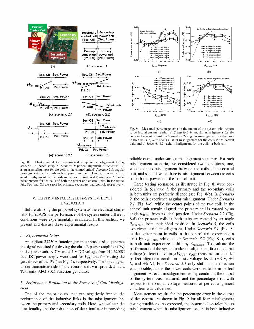
Fig. 8. Illustration of the experimental setup and misalignment testingscenarios: a) bench setup, b) Scenario 1: perfect alignment, c) Scenario 2.1:angular misalignment for the coils in the control unit, d) Scenario 2.2: angularmisalignment for the coils in both power and control units, e) Scenario 3.1:axial misalignment for the coils in the control unit, and f) Scenario 3.2: axialmisalignment for the coils of both the power and control units. In the figure,Pri., Sec. and Ctl are short for primary, secondary and control, respectively.
V. EXPERIMENTAL RESULTS-SYSTEM LEVELEVALUATION
Before utilizing the proposed system as the electrical stimu-lator for iEAPS, the performance of the system under differentconditions were experimentally evaluated. In this section, wepresent and discuss these experimental results.
A. Experimental Setup
An Agilent 33250A function generator was used to generatethe signal required for driving the class E power amplifier (PA)in the power unit. A 7 V and a 5 V DC voltage from HP 6205Cdual DC power supply were used for VDD and for biasing thegate driver of the PA (see Fig. 5), respectively. The input signalto the transmitter side of the control unit was provided via aTektronix AFG 3021 function generator.
B. Performance Evaluation in the Presence of Coil Misalign-ment
One of the major issues that can negatively impact theperformance of the inductive links is the misalignment be-tween the primary and secondary coils. Here, we evaluate thefunctionality and the robustness of the stimulator in providing
-15 -10 -5 0 5 10 15 20 25 30-0.25
0.00
0.25
Under the perfect alignment condition
Sys
tem
out
put e
rror
(%)
ctl_coil (Degree)
+3V system output +4V system output +5V system output -3V system output -4V system output -5V system output
(a)
-0.50 -0.25 0.00 0.25 0.50 0.75-1.00
-0.75
-0.50
-0.25
0.00
0.25Under the perfect alignment condition
+3V system output +4V system output +5V system output -3V system output -4V system output -5V system output S
yste
m o
utpu
t err
or (%
)
dboth_coils (cm)
(b)
0.00 0.25 0.50 0.75 1.00 1.25 1.50-0.50
-0.25
0.00
0.25
Under the perfect alignment condition
+3V system output +4V system output +5V system output -3V system output -4V system output -5V system output
Sys
tem
out
put e
rror
(%)
dctl_coil (cm)
(c)
-0.50 -0.25 0.00 0.25 0.50 0.75-1.00
-0.75
-0.50
-0.25
0.00
0.25Under the perfect alignment condition
+3V system output +4V system output +5V system output -3V system output -4V system output -5V system output S
yste
m o
utpu
t err
or (%
)
dboth_coils (cm)
(d)
Fig. 9. Measured percentage error in the output of the system with respectto perfect alignment, under: a) Scenario 2.1- angular misalignment for thecoils in the control unit, b) Scenario 2.2- angular misalignment for the coilsin both units, c) Scenario 3.1- axial misalignment for the coils in the controlunit, and d) Scenario 3.2- axial misalignment for the coils in both units.
reliable output under various misalignment scenarios. For eachmisalignment scenario, we considered two conditions, one,when there is misalignment between the coils of the controlunit, and second, when there is misalignment between the coilsof both the power and the control unit.
Three testing scenarios, as illustrated in Fig. 8, were con-sidered. In Scenario 1, the primary and the secondary coilsin both units are perfectly aligned (see Fig. 8-b). In Scenario2, the coils experience angular misalignment. Under Scenario2.1 (Fig. 8-c), while the center points of the two coils in thecontrol unit remain aligned, the primary coil is rotated by anangle θctl coil from its ideal position. Under Scenario 2.2 (Fig.8-d) the primary coils in both units are rotated by an angleθboth coils from their ideal position. In Scenario 3, the coilsexperience axial misalignment. Under Scenario 3.1 (Fig. 8-e) the center point in coils in the control unit experience ashift by dctl coils, while under Scenario 3.2 (Fig. 8-f), coilsin both unit experience a shift by dboth coils. To evaluate theperformance of the system under misalignment, first the outputvoltage (differential voltage VOUT+-VOUT-) was measured underperfect alignment condition at six voltage levels (±3 V, ±4V, and ±5 V). For Scenario 3.1 only shift in one directionwas possible, as the the power coils were set to be in perfectalignment. At each misalignment testing condition, the outputof the system was measured, and the percentage error withrespect to the output voltage measured at perfect alignmentcondition was calculated.
Measurement results for the percentage error in the outputof the system are shown in Fig. 9 for all four misalignmenttesting conditions. As expected, the system is less tolerable tomisalignment when the misalignment occurs in both inductive
Input Frequency (MHz)
VOUT+- VOUT- (V)
VOUT (V)
VLOGIC Logic "0"
Logic "1"
Logic "0"
Logic "1"
Regime 2
VCONTROL (V)
Regime 1
Dead zone 2.91 2.94 2.97 3.00 3.03 3.06 3.09
Input Frequency (MHz)
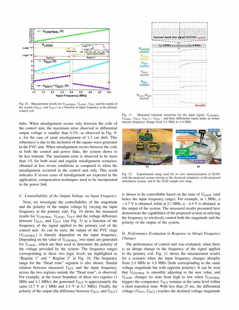
Fig. 10. Measurement results for VCONTROL, VLOGIC, VOUT and the output ofthe system (VOUT+ and VOUT-) as a function of input frequency at the primarycontrol coil.
links. When misalignment occurs only between the coils ofthe control unit, the maximum error observed in differentialoutput voltage is smaller than 0.5%, as observed in Fig. 9-c, for the case of axial misalignment of 1.5 cm shift. Thisrobustness is due to the inclusion of the square-wave generatorin the FVC unit. When misalignment occurs between the coilsin both the control and power links, the system shows tobe less tolerant. The maximum error is observed to be morethan 1% for both axial and angular misalignment scenarios,obtained at less severe conditions as compared to when themisalignment occurred in the control unit only. This resultindicates if severe cases of misalignment are expected in theapplication, compensation techniques need to be incorporatedin the power link.
C. Controllability of the Output Voltage via Input Frequency
Next, we investigate the controllability of the magnitudeand the polarity of the output voltage by varying the inputfrequency at the primary side. Fig. 10 shows the measuredresults for VCONTROL, VLOGIC, VOUT and the voltage differencebetween VOUT+ and VOUT- (see Fig. 3) as a function of thefrequency of the signal applied to the primary coil of thecontrol unit. As can be seen, the output of the FVC stage(VCONTROL) is linearly dependent on the input frequency.Depending on the value of VCONTROL, two states are generatedfor VLOGIC, which are then used to determine the polarity ofthe voltage provided by the system. The frequency rangescorresponding to these two logic levels are highlighted as“Regime 1” and “ Regime 2” in Fig. 10. The frequencyrange for the “Dead zone” segment is also shown. Similarrelation between measured VOUT and the input frequency,across the two regimes outside the “Dead zone”, is observed.For example, at the lower boundary of these two regimes (1MHz and 3.1 MHz), the generated VOUT is approximately thesame (2.7 V at 1 MHz and 2.8 V at 3.1 MHz). Finally, thepolarity of the output (the difference between VOUT+ and VOUT-)
Fig. 11. Measured transient waveform for the input signal, VCONTROL,VLOGIC, VOUT, VOUT+, VOUT− and their differential signal under an instan-taneous frequency change from 2.8 MHz to 4.9 MHz.
Fig. 12. Experimental setup used for in vitro characterization of iEAPswith the proposed system serving as the electrical stimulator, a) the proposedstimulation system, and b) the iEAP sample test setup.
is shown to be controllable based on the state of VLOGIC (andhence the input frequency range). For example, at 1 MHz, a+2.7 V is obtained, while at 3.1 MHz, a −2.8 V is obtained, atthe output of the system. The measured results presented heredemonstrate the capabilities of the proposed system in utilizingthe frequency to wirelessly control both the magnitude and thepolarity of the output of the system.
D. Performance Evaluation in Response to Abrupt FrequencyChanges
The performance of control unit was evaluated, when thereis an abrupt change in the frequency of the signal appliedto the primary coil. Fig. 11 shows the measurement resultsfor a scenario when the input frequency changes abruptlyfrom 2.8 MHz to 4.9 MHz (both corresponding to the samevoltage magnitude but with opposite polarity). It can be seenthat VCONTROL is smoothly adjusting to the new value, andVLOGIC changes its state from high to low when VCONTROLtriggers the comparator. VOUT remains at the same level withina short transition time. With less than 25 ms, the differentialvoltage (VOUT+-VOUT-) reaches the destined voltage magnitude

Fig. 13. Top view of a) the initial state of the iEAP sample in the absence of electric field, b) and c) the iEAP sample bends after 3 minutes of continuouselectrical stimulation at +5 V and −5 V.
and polarity. This response time, which is comparable to theresponse time of muscles [53], can be further adjusted by thecomponents used in the system (e.g. the settling time of RLPF
and CLPF components in Fig. 7).
VI. EXPERIMENTAL RESULTS-In VitroCHARACTERIZATION
The proposed system was used as the electrical stimulatorfor iEAP samples. The functionality of the end-to-end systemwas evaluated based on the movement characteristics of iEAPsamples while being stimulated by the proposed system. Twotesting conditions were considered. First, the movement ofiEAPs in terms of the rate of change in the bending angle(angular speed) was characterized when the sample is con-tinuously stimulated at a fixed voltage over a given durationof time [54]. Second, changes in the bending angle of iEAPswhen there is an abrupt change in the input frequency werestudied. For each test, four samples were used, which is atypical sample size for characterizing iEAPs [13]. In thissection, we present and discuss the results of these in vitromeasurements.
A. Experimental Setup
Fig. 12 illustrates the in vitro measurement setup. Theoutput of the proposed system was used to provide theelectrical stimulation to the iEAP samples, via two Platinum(Pt) electrodes that on one end are attached to the VOUT+and VOUT- terminals of the stimulator (see Fig. 12-a). Theseelectrodes are suspended, 3 cm apart from one another, in awell of PBS solution, which has similar ion concentrationsas body fluids [14]. The distance was decided based on pastexperiments with similar iEAP samples [14], [54]. The PAA-PEG hydrogel sample, with a dimension of 20 × 4 × 0.76mm3, was propped up between two pegs between the twoelectrodes. Pegs hold the sample in place during the test andprevent it from displacing between the electrodes. To improvethe visibility of the iEAP sample in Fig. 12, the sample wassoaked in green dye (normally, samples are transparent). Notethat although these experiments do not explicitly use the mediaused in typical in vitro experiments (such as tissue culturemedia), the aspect of the media (ionic environment) that leadsto the movement of iEAPs (when implanted in the body) hasbeen considered similar to what is seen in PBS. Similar invitro experimental setup has been previously used in [13].
B. Movement Characterization: Angular Speed
To evaluate how iEAPs respond to electrical stimulationprovided by the proposed system, their movement was char-acterized by measuring the angular speed for different inputfrequencies. The angular speed has been previously used tocharacterize the movement of similar scaffolds [13], [14], [54]and was used here again to ensure the effectiveness of thetesting protocol. The angular speed for a given input frequencyis obtained as follows. With the initial state being the absenceof electrical stimulation (time = 0), the input frequency is setto a given value, and is held for 3 minutes. The movementof the iEAP samples are then videotaped. The angle at whichthe sample reaches (with respect to its initial state) after 3minutes of continuous stimulation is measured. The angularspeed is then calculated as this measured angle divided by theduration of stimulation (3 minutes) [54]. Figs. 13-a, 13-b and13-c show top view of an iEAP sample being at the initial state(no electrical stimulation), and after 3 minutes of continuouselectrical stimulation at two voltage conditions, respectively.
Measuring angular speed was performed at six differentfrequencies: 1.2 MHz (corresponding to +3 V), 2.0 MHz(corresponding to +4 V), 2.8 MHz (corresponding to +5 V),3.2 MHz (corresponding to −3 V), 4.1 MHz (corresponding to−4 V) and 4.9 MHz (corresponding to −5 V). Fig. 14 showsthe averaged angular speed and 1σ variation across samples,obtained for each frequency. The voltage generated by thesystem for each input frequency value is also shown (in red).As can be seen, the measured angular speed is proportionalto the applied voltage, as expected [14], [54]. It can alsobe observed that for the positive and the negative polaritiesof a given voltage value, the angular speed that the iEAPsamples achieve are almost the same. Results obtained hereare also comparable with what we had previously reportedin [14] where electrical stimulations to iEAP samples wereprovided by directly changing the voltage levels using an LDO.These results demonstrate the feasibility of using the proposedsystem as a reliable wireless electrical stimulator for the iEAPsamples.
C. Movement Characterization: Response to Rapid FrequencyChanges
Next, we studied how the iEAPs respond when there is asudden change in the frequency at the input of the proposedstimulator. To perform such a study, the input frequency was
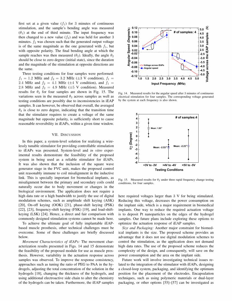
first set at a given value (f1) for 3 minutes of continuousstimulation, and the sample’s bending angle was measured(θ1) at the end of third minute. The input frequency wasthen changed to a new value (f2) and was held for another 3minutes. f2 was chosen such that the generated output voltageis of the same magnitude as the one generated with f1, butwith opposite polarity. The final bending angle at which thesample reaches was then measured (θ2). Ideally, the angle θ2should be close to zero degree (initial state), since the durationand the magnitude of the stimulation at opposite directions arethe same.
Three testing conditions for four samples were performed:f1 = 1.2 MHz and f2 = 3.2 MHz (±3 V condition), f1 =2.4 MHz and f2 = 4.1 MHz (±4 V condition), and f1 =2.8 MHz and f2 = 4.9 MHz (±5 V condition). Measuredresults for θ2 for four samples are shown in Fig. 15. Thevariations seen in the measured θ2 across samples as well astesting conditions are possibly due to inconsistencies in iEAPsamples. It can however, be observed that overall, the averagedθ2 is close to zero degree, indicating that the transition timethat the stimulator requires to create a voltage of the samemagnitude but opposite polarity, is sufficiently short to causereasonable reversibility in iEAPs, within a given time window.
VII. DISCUSSION
In this paper, a system-level solution for realizing a wire-lessly tunable stimulator for providing controllable stimulationto iEAPs was presented. System-level and in vitro exper-imental results demonstrate the feasibility of the proposedsystem in being used as a reliable stimulator for iEAPs.It was also shown that the inclusion of the square wavegenerator stage in the FVC unit, makes the proposed controlunit reasonably immune to coil misalignment in the inductivelink. This is specially important for biomedical implants, asmisalignment between the primary and secondary coils couldnaturally occur due to body movement or changes in thebiological environment. The application does not require ahigh data rate or a high bandwidth to justify the use of digitalmodulation schemes, such as amplitude shift keying (ASK)[20], On-off keying (OOK) [21], phase-shift keying (PSK)[22], [23], frequency-shift keying (FSK) [19], and load-shift-keying (LSK) [24]. Hence, a direct and fair comparison withcommonly designed stimulation systems cannot be made here.
To achieve the ultimate goal of fully implantable iEAP-based muscle prosthesis, other technical challenges must beovercome. Some of these challenges are briefly discussedbelow.
Movement Characteristics of iEAPs: The movement char-acterization results presented in Figs. 14 and 15 demonstratethe feasibility of the proposed module for use as muscle pros-thesis. However, variability in the actuation response acrosssamples was observed. To improve the response consistency,approaches such as tuning the ratio of PEG to PAA in the hy-drogels, adjusting the total concentration of the solution in thehydrogels [18], changing the thickness of the hydrogels, andusing additional electroactive side chain to alter the chemistryof the hydrogels can be taken. Furthermore, the iEAP samples
1.0 1.5 2.0 2.5 3.0 3.5 4.0 4.5 5.0-0.12-0.10-0.08-0.06-0.04-0.020.020.040.060.080.100.12
Angular speed
# of samples: 4
Volta
ge a
cros
s th
e iE
AP s
ampl
es
(V)
Angu
lar S
peed
(Deg
ree/
s)
Input Frequency (MHz)
-5.0-4.5-4.0-3.5-3.0-2.52.53.03.54.04.55.0
Voltage across iEAPs
Fig. 14. Measured results for the angular speed after 3 minutes of continuouselectrical stimulation for four samples. The corresponding voltage generatedby the system at each frequency is also shown.
-6-5-4-3-2-1012345
# of samples:4
Mean: -2.23oMean: -2.53o
Mean: 1.85 o
+3V to -3V +4V to -4V +5V to -5V
Testing Conditions
q 2 (D
egre
e)
Fig. 15. Measured results for θ2 under three rapid frequency change testingconditions, for four samples.
here required voltages larger than 3 V for being stimulated.Reducing this voltage, decreases the power consumption onthe implant side, which is a major requirement in biomedicalimplants. One way to reduce the required actuation voltageis to deposit Pt nanoparticles on the edges of the hydrogelsamples. Our future plans include exploring these options tooptimize the actuation response of iEAP samples.
Size and Packaging: Another major constraint for biomed-ical implants is the size. The proposed scheme provides anadvantage that it does not use digital modulation schemes tocontrol the stimulation, as the application does not demandhigh data rates. The use of the proposed scheme reduces thecomplexity of the design, and consequently, will save on thepower consumption and the area on the implant side.
Future work will involve investigating technical issues re-lated to the integration of the stimulator with iEAPs, designinga closed-loop system, packaging, and identifying the optimumposition for the placement of the electrodes. Encapsulationtechniques, such as using polymeric materials or dual-layerpackaging, or other options [55]–[57] can be investigated as

possible solutions.
VIII. CONCLUSIONS
A new tunable electrical stimulation system for iEAPs waspresented in this paper. The system employs a reliable designsolution to remotely control both the degree and the directionof the movement of iEAP samples, without incorporatingdigital modulation schemes, thereby saving on the size andthe design complexity, making it suitable for subcutaneousapplications. Extensive board-level and in vitro experimentalresults demonstrated the feasibility of the proposed systemin providing reliable electrical stimulation to iEAPs. Whenintegrated with iEAPs, the module has the potential to beused as part of subcutaneous technologies to provide functionand regeneration of lost tissue in a timely manner, followingimplantation.
ACKNOWLEDGMENT
The authors are grateful to Sanjeevi Thirumurgusan andJingxuan Chen for their help with the PCB layout and ex-periments.
REFERENCES
[1] B. R. Brooks, R. G. Miller, M. Swash, and T. L. Munsat, “El Esco-rial revisited: revised criteria for the diagnosis of amyotrophic lateralsclerosis,” Amyotrophic Lateral Sclerosis, vol. 1, no. 5, pp. 293–299,2000.
[2] K. Ziegler-Graham, E. J. MacKenzie, P. L. Ephraim, T. G. Travison, andR. Brookmeyer, “Estimating the prevalence of limb loss in the UnitedStates: 2005 to 2050,” Archives of physical medicine and rehabilitation,vol. 89, no. 3, pp. 422–429, 2008.
[3] Y. Huang, F. Kong, J. Freeman, and L. Najafizadeh, “A low drop-outregulator for subcutaneous electrical stimulation of nanofibers used inmuscle prosthesis,” in IEEE Biomedical Circuits and Systems Confer-ence, Oct. 2015, pp. 101–104.
[4] A. Bach, J. Beier, J. Stern-Staeter, and R. Horch, “Skeletal muscle tissueengineering,” Journal of cellular and molecular medicine, vol. 8, no. 4,pp. 413–422, 2004.
[5] W. Bian and N. Bursac, “Engineered skeletal muscle tissue networkswith controllable architecture,” Biomaterials, vol. 30, no. 7, pp. 1401–1412, 2009.
[6] K. McKeon-Fischer, D. Flagg, and J. Freeman, “Coaxial electrospunpoly (ε-caprolactone), multiwalled carbon nanotubes, and polyacrylicacid/polyvinyl alcohol scaffold for skeletal muscle tissue engineering,”J. of Biomedical Materials Research Part A, vol. 99, no. 3, pp. 493–499,2011.
[7] K. McKeon-Fischer, J. H. Rossmeisl, A. R. Whittington, and J. W.Freeman, “In vivo skeletal muscle biocompatibility of composite, coaxialelectrospun, and microfibrous scaffolds,” Tissue Engineering Part A,vol. 20, no. 13-14, pp. 1961–1970, 2014.
[8] K. Kruusamae, A. Punning, A. Aabloo, and K. Asaka, “Self-sensingionic polymer actuators: a review,” in Actuators, vol. 4, no. 1, 2015, pp.17–38.
[9] I. Fasolino, V. Guarino, V. Cirillo, and L. Ambrosio, “5-azacytidinemediated hMSC behaviour on electrospun scaffolds for skeletal muscleregeneration,” Journal of Biomedical Materials Research Part A, 2017.
[10] F. Carpi and E. Smela, Biomedical Applications of Electroactive PolymerActuators. Wiley, 2009.
[11] Y. Huang and L. Najafizadeh, “A wirelessly tunable low drop-outregulator for subcutaneous muscle prosthesis,” in IEEE InternationalSymposium on Circuits and Systems (ISCAS), 2016, pp. 850–853.
[12] D. Becker, D. S. Gary, E. S. Rosenzweig, W. M. Grill, and J. W.McDonald, “Functional electrical stimulation helps replenish progenitorcells in the injured spinal cord of adult rats,” Experimental neurology,vol. 222, no. 2, pp. 211–218, 2010.
[13] D. Browe, C. Wood, M. Sze, K. White, T. Scott, R. Olabisi, and J. Free-man, “Characterization and optimization of actuating poly(ethyleneglycol) diacrylate/acrylic acid hydrogels as artificial muscles,” Polymer(In Press, Accepted Manuscript).
[14] Y. Huang, D. Browe, S. Thirumurugesan, J. Freeman, and L. Na-jafizadeh, “In Vitro characterization of electronically stimulated ionicelectroactive polymers with application to muscle prosthesis,” in IEEEBiomedical Circuits and Systems Conference, 2016, pp. 428–431.
[15] M. Shahinpoor and K. J. Kim, “Ionic polymer-metal composites: I.Fundamentals,” Smart materials and structures, vol. 10, no. 4, p. 819,2001.
[16] E. P. Widmaier, H. Raff, and K. T. Strang, Vander’s human physiology.McGraw Hill Boston, USA, 2006.
[17] W. Cui, L. Liu, and X. Zhu, “Bending behaviors of electroresponsivePVA/PAA SIPN hydrogels under electric field,” in 6th InternationalForum on Strategic Technology (IFOST), vol. 1, 2011, pp. 122–125.
[18] S. J. Kim, S. J. Park, S. G. Yoon, I. Y. Kim, and S. I. Kim, “Characteri-zation of smart hydrogels for biometric sensors and actuators,” in IEEEEMBS Asian-Pacific Conference on Biomedical Engineering, 2003.
[19] M. Ghovanloo and K. Najafi, “A wideband frequency-shift keyingwireless link for inductively powered biomedical implants,” IEEE Trans-actions on Circuits and Systems I, vol. 51, no. 12, pp. 2374–2383, 2004.
[20] G. Yilmaz, O. Atasoy, and C. Dehollain, “Wireless energy and datatransfer for in-vivo epileptic focus localization,” IEEE Sensors Journal,vol. 13, no. 11, pp. 4172–4179, 2013.
[21] E. G. Kilinc, C. Baj-Rossi, S. Ghoreishizadeh, S. Riario, F. Stradolini,C. Boero, G. De Micheli, F. Maloberti, S. Carrara, and C. Dehollain, “Asystem for wireless power transfer and data communication of long-termbio-monitoring,” IEEE Sensors Journal, vol. 15, no. 11, pp. 6559–6569,2015.
[22] M. Monge, M. Raj, M. H. Nazari, H.-C. Chang, Y. Zhao, J. D. Weiland,M. S. Humayun, Y.-C. Tai, and A. Emami, “A fully intraocular high-density self-calibrating epiretinal prosthesis,” IEEE Trans. on BiomedicalCircuits and Systems, vol. 7, no. 6, pp. 747–760, 2013.
[23] S.-Y. Lee, C.-H. Hsieh, and C.-M. Yang, “Wireless front-end with powermanagement for an implantable cardiac microstimulator,” IEEE Trans.on Biomedical Circuits and Systems, vol. 6, no. 1, pp. 28–38, 2012.
[24] J. Zhao, L. Yao, R.-F. Xue, P. Li, M. Je, and Y. P. Xu, “An integratedwireless power management and data telemetry IC for high-compliance-voltage electrical stimulation applications,” IEEE Trans. on BiomedicalCircuits and Systems, vol. 10, no. 1, pp. 113–124, 2016.
[25] H. Toreyin and P. Bhatti, “A field-programmable analog array de-velopment platform for vestibular prosthesis signal processing,” IEEEtransactions on biomedical circuits and systems, vol. 7, no. 3, pp. 319–325, 2013.
[26] A. K. RamRakhyani, S. Mirabbasi, and M. Chiao, “Design and optimiza-tion of resonance-based efficient wireless power delivery systems forbiomedical implants,” IEEE Trans. on Biomedical Circuits and Systems,vol. 5, no. 1, pp. 48–63, 2011.
[27] G. Simard, M. Sawan, and D. Massicotte, “High-speed OQPSK andefficient power transfer through inductive link for biomedical implants,”IEEE Trans. on Biomedical Circuits and Systems, vol. 4, no. 3, pp.192–200, 2010.
[28] F. Kong, Y. Huang, and L. Najafizadeh, “A coil misalignment compen-sation concept for wireless power transfer links in biomedical implants,”in IEEE Wireless Power Transfer Conference (WPTC), 2015, pp. 1–4.
[29] Y. Huang, D. Browe, J. Freeman, and L. Najafizadeh, “Live demon-stration: A frequency-based system for wireless electrical stimulationof ieaps,” in IEEE International Symposium on Circuits and Systems(ISCAS), 2017, pp. 1–1.
[30] “REG101 data sheet,” Texas Instruments, Dallas, Texas.[31] “AD8397 data sheet,” Analog Devices, Norwood, Massachusetts.[32] “MAX4855 data sheet,” Maxim Integrated, San Jose, California.[33] B. Lee, M. Kiani, and M. Ghovanloo, “A triple-loop inductive power
transmission system for biomedical applications,” IEEE Trans. onBiomedical Circuits and Systems, vol. 10, no. 1, pp. 138–148, 2016.
[34] J. Coulombe, M. Sawan, and J.-F. Gervais, “A highly flexible systemfor microstimulation of the visual cortex: Design and implementation,”IEEE Trans. on Biomedical Circuits and Systems, vol. 1, no. 4, pp.258–269, 2007.
[35] M. Karimi, A. M. Sodagar, M. E. Mofrad, and P. Amiri, “Auxiliary-carrier load-shift keying for reverse data telemetry from biomedical im-plants,” in IEEE Biomedical Circuits and Systems Conference (BioCAS),2012, pp. 220–223.
[36] L. H. Jung, P. Byrnes-Preston, R. Hessler, T. Lehmann, G. Suaning, andN. H. Lovell, “A dual band wireless power and fsk data telemetry forbiomedical implants,” in Annual International Conference of the IEEEEngineering in Medicine and Biology Society, 2007, pp. 6596–6599.
[37] W. Liu, K. Vichienchom, M. Clements, S. C. DeMarco, C. Hughes,E. McGucken, M. S. Humayun, E. De Juan, J. D. Weiland, andR. Greenberg, “A neuro-stimulus chip with telemetry unit for retinal

prosthetic device,” IEEE J. of Solid-State Circuits, vol. 35, no. 10, pp.1487–1497, 2000.
[38] K. M. Silay, C. Dehollain, and M. Declercq, “Inductive power link fora wireless cortical implant with two-body packaging,” IEEE SensorsJournal, vol. 11, no. 11, pp. 2825–2833, 2011.
[39] ——, “A closed-loop remote powering link for wireless cortical im-plants,” IEEE Sensors Journal, vol. 13, no. 9, pp. 3226–3235, 2013.
[40] T. T. Nguyen, L. A. L. Fernandes, and P. Hafliger, “An energy-efficientimplantable transponder for biomedical piezo-resistance pressure sen-sors,” IEEE Sensors Journal, vol. 14, no. 6, pp. 1836–1843, 2014.
[41] J. Y. Shin, J.-H. Ahn, K. Pi, D.-i. D. Cho, and Y. S. Goo, “Electrodeless,non-invasive stimulation of retinal neurons using time-varying magneticfields,” IEEE Sensors Journal, vol. 16, no. 24, pp. 8832 – 8839, 2015.
[42] P. Cong, W. H. Ko, and D. J. Young, “Wireless batteryless implantableblood pressure monitoring microsystem for small laboratory animals,”IEEE Sensors Journal, vol. 10, no. 2, pp. 243–254, 2010.
[43] E. G. Kilinc, G. Conus, C. Weber, B. Kawkabani, F. Maloberti, andC. Dehollain, “A system for wireless power transfer of micro-systemsin-vivo implantable in freely moving animals,” IEEE Sensors Journal,vol. 14, no. 2, pp. 522–531, 2014.
[44] B. M. Badr, R. Somogyi-Gsizmazia, K. R. Delaney, and N. Dechev,“Wireless power transfer for telemetric devices with variable orientation,for small rodent behavior monitoring,” IEEE Sensors Journal, vol. 15,no. 4, pp. 2144–2156, 2015.
[45] P. Yeon, S. A. Mirbozorgi, and M. Ghovanloo, “Optimal design of a3-coil inductive link for millimeter-sized biomedical implants,” in IEEEBiomedical Circuits and Systems Conference (BioCAS), 2016, pp. 396–399.
[46] N. O. Sokal and A. D. Sokal, “Class E-A new class of high-efficiencytuned single-ended switching power amplifiers,” IEEE J. of solid-statecircuits, vol. 10, no. 3, pp. 168–176, 1975.
[47] M. Kiani and M. Ghovanloo, “Near-Field Wireless Power and DataTransmission to Implantable Neuroprosthetic Devices,” in Neural Com-putation, Neural Devices, and Neural Prosthesis. Springer, 2014, pp.189–215.
[48] C. Sauer, M. Stanacevic, G. Cauwenberghs, and N. Thakor, “Powerharvesting and telemetry in CMOS for implanted devices,” IEEE Trans-actions on Circuits and Systems I: Regular Papers, vol. 52, no. 12, pp.2605–2613, 2005.
[49] “AN-88: CMOS Linear Applications,” Applications Note, FairchildSemiconductor, 2003.
[50] RCA Solid State Division, COS/MOS Integrated Circuits Manual, 1972.[51] “SN74LVC1G123-Q100 data sheet,” Nexperia Inc., Netherlands.[52] J. Millman and A. Grabel, Microelectronics. McGraw-Hill, 1987.[53] K. Yotani, H. Nakamoto, S. Ikudome, and A. Yuki, “Muscle contraction
and relaxation-response time in response to on or off status of visualstimulus,” Journal of physiological anthropology, vol. 33, no. 1, p. 23,2014.
[54] K. McKeon-Fischer, D. Flagg, and J. Freeman, “Poly (acrylic acid)/poly(vinyl alcohol) compositions coaxially electrospun with poly (-caprolactone) and multi-walled carbon nanotubes to create nanoactuatingscaffolds,” Polymer, vol. 52, no. 21, pp. 4736–4743, 2011.
[55] D. Welch and J. B. Christen, “Seamless integration of cmos andmicrofluidics using flip chip bonding,” Journal of Micromechanics andMicroengineering, vol. 23, no. 3, p. 035009, 2013.
[56] R. Jegadeesan, S. Nag, K. Agarwal, N. V. Thakor, and Y.-X. Guo, “En-abling wireless powering and telemetry for peripheral nerve implants,”IEEE J. of Biomedical and Health Informatics, vol. 19, no. 3, pp. 958–970, 2015.
[57] A. Cavallini, T. R. Jost, S. S. Ghoreishizadeh, J. Olivo, M. O. de Beeck,B. Gorissen, F. Grassi, G. De Micheli, and S. Carrara, “A subcutaneousbiochip for remote monitoring of human metabolism: packaging andbiocompatibility assessment,” IEEE Sensors Journal, vol. 15, no. 1, pp.417–424, 2015.
Yi Huang (S’14) received his B.S. degree fromBeijing University of Aeronautics and Astronautics,China, his M.S. from Stony Brook University-StateUniversity of New York, and his Ph.D. from RutgersUniversity, Piscataway, NJ. He has currently holdsthe position of Senior Applications Engineer at theIntersil Corporation, New Jersey development center.His research interests include analog/mixed-signalcircuit design for biomedical applications, and con-trol and modeling of power electronics converters. Yiis the recipient of 2016 IEEE Circuits and Systems
Society (CAS) student travel award, and the best student paper award (RunnerUp) from the 2014 IEEE International Symposium on Circuits and Systems(ISCAS).
Daniel Browe graduated from the University ofPittsburgh in 2012 with a B.S. in Bioengineering anda concentration in Biomechanics. He has since beenworking in the laboratory of Dr. Joseph Freeman atRutgers University to pursue a Ph.D. in BiomedicalEngineering. His thesis project is on the design andoptimization of an actuating scaffold for skeletalmuscle tissue engineering.
Joseph Freeman is an Associate Professor in theDepartment of Biomedical Engineering at RutgersUniversity. He received his bachelors degree inChemical Engineering from Princeton University in1997, his doctorate in Biomedical Engineering fromRutgers University and the University of Medicineand Dentistry of New Jersey in 2003.
Dr. Freemans expertise is in the area of muscu-loskeletal tissue engineering. As the director of theMusculoskeletal Tissue Regeneration (MoTR) Lab-oratory he develops novel biomaterials and scaffolds
for the replacement and regeneration of ligament, tendon, muscle, and bone.Dr. Freeman also has active projects in the areas of cancer research andligament healing therapies. He is an Editorial Board member of PhysicalReview Applied and Regenerative Engineering and Translational Medicine.Dr. Freeman has co-authored over 50 articles in peer reviewed journals andhas been a guest editor for Materials Science and Engineering: Part-C andNano Life. He is a past recipient of the Coulter Foundation Early CareerTranslational Research Award, a Ford Foundation Fellow, and a RutgersChancellors Scholar.
Laleh Najafizadeh (SM’17) received her B.Sc. fromIsfahan University of Technology, Isfahan, Iran, herM.Sc. from the University of Alberta, Edmonton,AB, Canada, and her Ph.D. from the Georgia In-stitute of Technology, Atlanta, GA, USA, all inElectrical Engineering. From 2003 to 2004, she waswith the iCORE Wireless Communications Labora-tory at the University of Alberta, and from 2010 to2012 she was a postdoctoral fellow at the NationalInstitutes of Health (NIH), Bethesda, MD, USA. Shecurrently is an Assistant Professor in the Department
of Electrical and Computer Engineering, at Rutgers University, Piscataway,NJ.
Dr. Najafizadeh is a member of the Analog Signal Processing TechnicalCommittee (ASPTC) of the IEEE Circuits and Systems Society (CASS), andtechnical committee member of IEEE BCICTS, and is the publication chair forthe 2018 IEEE Biomedical Circuits and Systems Conference (BioCAS). Shehas co-authored two book chapters and more than 80 peer-reviewed papers inpremier journals and conference proceedings. Dr. Najafizadeh is the recipientof a Texas Instruments Leadership Fellowship, a Delta Kappa Gamma WorldFellowship, and competitive scholarships from the Alberta Ingenuity Fund,and the Alberta Informatics Circle of Research Excellence. Together with herstudents she received the best student paper award (Runner-Up) from the 2014IEEE ISCAS.