Embed Size (px)
Citation preview

A visual environment to define composition of interacting graphical objects
G.P. F a c o n t i a n d F. P a t e r n 6
C N U C E - C.N.R. , Via S. Mar ia , 36, 1-56100 Pisa, I taly
This work presents the FP visual language that specifies the components of a user in- terface and their relationship. Each com- ponent is an instance of an interactor that is a general description of a basic graphical interaction. By a visual language, it is pos- sible to specify in a flexible way the logical structure of a user interface defined as a composition of interacting graphical ob- jects. The graphical tool allows the design- er to investigate the correctness of user in- terfaces and their properties.
Key words: Graphical interaction - User interface management systems - Visual languages
Correspondence to: F. Pa te rn6
1 Introduction
A user interface management system (UIMS) (Duce et al. 1991) is comprised of a run-time sup- port system and a set of design, specification, and evaluation tools. New trends in designing the archi- tectures of UIMS (Duce et al. 1991; Bass and Coutaz 1991) focus on the description of sets of autonomous cooperating components exchanging input/output data and control information. The practical consequence of this approach results in the management of a very large number of logical modules working concurrently and communicating through a network that may quickly become very complex. Consequently, the logical structure of such an environment is more complicated with re- spect to traditional user interfaces. Programmers have shown difficulties in specifying their application exploiting the capabilities of par- allel languages mainly due to their custom of rea- soning and working in a sequential way using se- quential systems. One important problem is that in a textual parallel language the relationship across the modules realized by the concurrent com- mands are difficult to understand and to remember. This implies that the user interface designer has difficulties in obtaining correct specifications and investigating their properties, especially when using a parallel approach. A new generation of visual languages (Shu 1985), based on the direct manipulation of multidimen- sional objects for building programming constructs has been proven to be of great help for specifying complex environments. These languages allow for an application to be graphically described, obtain- ing a specification that is easier to realize and intui- tively clearer. Using visual languages, the produc- tivity of programmers and users is dramatically in- creased with respect to the use of traditional meth- ods. By directly manipulating graphical objects and specifying their relationship in a bidimensional space, it is possible to obtain representations closer to their conceptual model. Chang (1986) distinguished the visual languages in four categories: iconic languages for visual pro- gramming using a visual representation for lan- guage constructs and for objects not inherently vi- sual; iconic languages to process visual information that appear to the user as graphical representations for objects such as images; textual languages to support visual interaction, that make it possible to realize graphical interactions (such as GKS, PHIGS, PostScript and Xlib; textual languages to process visual information that manipulate images
The Visual Computer (1992) 9: 73-83 ,-/r) �9 Springer-Verlag 1992 1 0

and similar data common in the field of image pro- cessing, office automation, and robotics. Following Chang's categorization, the aim of our work is to define a graphical language for specify- ing the logical structure of user interfaces that are not inherently graphic objects. Within this frame- work, the graphical specification of the logical structure of a user interface is addressed by a visual language for describing the instances of interaction object or interactors (Faconti and Patern6 1989) and their relationships. A different taxonomy was also proposed by Myers (1990). He divides general programming languages depending on different criteria: languages based on visual programming (based on two or more dimen- sional specifications) or not on example-based pro- gramming or not interpretive or compiled. Visual programming is divided into two categories: 1) vi- sual programming systems groupded depending on how they represent the programs (using flowcharts, Petri nets, data flow graphs, matrices, forms, and iconic sentences) and 2) program visualization sys- tems (where graphics are used to illustrate some aspect of the program after it is written) classified depending on the constituents of programs they visualize, such as code, data, or underlying algor- ithmical structure. Here our system can be categor- ized under visual programming systems using data flow graphs as graphical representations. One of the most commonly used techniques in graphically specifying user interfaces is in editing state transition diagrams. As an example, Jacob (1986) uses this technique to describe both the syn- tactical and lexical entities in separated windows. A more direct approach is found in ConMan (1988). Here the programmer realizes different types of interaction, manipulation, and visualiza- tion of graphical objects by requesting the services of a connection manager that allows for dynamic connections between the components. However, there is not a uniform description of the architcture of such components. In Singh (1990), a visual envi- ronment that mainly creates instances of interac- tion techniques and interactively refines their ap- pearance is proposed, but the problem of creating higher-level interfaces by composing lower-level objects is not addressed.
2 Interactor model In our visual environment we have graphic objects, namely icons, whose meaning is to represent other
74
objects that are interactors; the difference is that the former ones are passive graphic representations (used in the specification phase) of the latter ones that have, other than the appearance (realized at run-time), also a dynamic behavior. A behavior of an interactor is further divided in two well-defined parts: - The external one, which has an influence on the modification of the external appearance towards the user. - The internal one, consisting of receiving, elabor- ating, and sending higher-level input data to other interactors or application processes. In this way, we integrate the approach of graphics systems, such as GKS and PHIGS, and the ap- proach of window-management-system toolkits. In the first ones, the logical input devices are charac- terized only by the data type they return (locator, pick and valuator) and the application program- mer cannot affect their external appearance. While in the latter the interaction techniques are modeled in a class tree depending on their external behavior. They allow the designer to obtain user interfaces that are a flat distribution of interaction techniques and that interact immediately with application pro- cedures. In fact, they can communicate among themselves only for layout management and ex- change of basic events of the underlying window system, but they cannot be composed to realize hierarchical input data processing. Visual language allows the specification of the logi- cal structure of user interfaces supporting a large set of functionalities:
- Unique description of objects f rom physical de- vices to applications.
- Generation of continuous and multiple feedback from within the user interface.
- Capability of handling multiple threads of interac- tion simultaneously.
- Extendability of functionality.
- Various ways to control the dialog between user interface and application.
To obtain these goals, user interfaces are logically developed by composition of interactors. One in- teractor is an entity supporting the conversion be- tween higher- and lower-level input and/or output in both directions. It has the aim of providing a general description of an interaction with graphical devices. Another attempt to encapsulate dynamic behavior of graphical interaction is in Myers

(1989), where a set of possible general descriptions are indicated while we are able to provide a unique abstract description for all possible interactions with graphical devices. In Duce et al. (1990), the hierarchical composition of only input devices is addressed. An interactor is seen by itself as a set of concurrent processes describing one basic graphical interac- tion. The capabilities of interactors have been de- scribed by using the typical constructs provided by concurrent languages to manage the exchange of messages, activate and deactivate processes, evaluate concurrent situations, and handle parallel- ism in general. This allows us to specify the cooper- ative tasks between the user interface components in a very flexible way. There have already been some proposals for ap- pliying concurrent languages to the user interface specification (Cardelli and Pike 1985; Hill 1986). One strong problem with using them is that the textual syntax of those languages has generally hid- den meanings and consequently the resulting pro- grams are not easily understood by non specialists. For this reason, it is obviously important to ad- dress the capabilities offered by visual program- ming (because they are more clear, more powerful, and the interrelations among different items are expressed in amore understandable way) to specify concurrent interactors and their behavior. A basic interaction unit, or interactor, mainly con- sists of five functions: - T r i g g e r , to identify a significant moment in time. - M e a s u r e , applied to the input data (when the trigger is verified) to build a new input data for the next higher level.
F e e d b a c k , to generate the output toward the user (a picture composed of lower-level output primi- tives). - C o l l e c t i o n , to describe the output primitives as- sociated with the interactor that are interpreted and sent to the feedback for visualization. - C o n t r o l , to deliver the result of the measure to other interactors or to the application. Each of these functionalities is distinguished by a set of parameters and all together make it possible to encapsulate the general behavior of a basic graphical interaction. A visual language for the graphical specification of the parameters indicating instances of interactors and their possible connec- tions is a powerful tool that gives the designer the capability to develop the user interface in more
easily. On the resulting specification, automatic tools can be applied to investigate properties and dynamic behavior.
3 What the language has to specify
The model of an i n t e r a c t o r was described through constructs of the ECSP concurrent language (Baiardi and Vanneschi 1985), which is an exten- sion of CSP (Hoare 1985) already used as specifica- tion language for graphical input (Duce et al. 1990). CSP is a formal notation to describe concurrent processes that communicate by synchronous events. ECSP provides, more than CSP, explicit and compact ways to use different protocols: sym- metric synchronous (where two components com- municate in a synchronous way), asymmetric syn- chronous (more processes can send data to one process in a synchronous way) and symmetric asynchronous (two processes communicate in an asynchronous way by a buffer) and has some dy- namic features, such as the capability of allocating communications channels by means of variables of type process name. These allow a process to use the same channel to receive data from different processes at different times. The channels are modi- fiable data that belong to the receiving process. It is possible to change the sender process part. An interactor can belong to three different categor- ies (input/output, input, output) depending on if it has an external and internal behavior, only the internal one, or only the external one. In the more general case (input/output), it can communicate with the outside by six channels (four input and two output channels) as presented in Fig. 1. It re- ceives input in four channels: one to receive control requests, one to receive the high-level output primi- tives defining the external appearance of the inter-
Output primitives for the collection
I Interactor tr igger measure traversa/
Picture (Result of Ihe external bel~avior) Input for the
measure function
Fig. 1. Interactor 's environment
Control requests Higher level input data
(Rcsull of /he inlernal behavior)
J
Input for the trigger function
75

actor into a collection, one to receive input to the trigger function, and one to receive input to the measure function. It generates output by two chan- nels: one to send the high level input data that it produces to other interactors or application pro- cesses (this defines its internal behaviour) and one to produce output information after having pro- cessed the primitives internally stored in a compo- sition (this defines its external behavior). Our graphical language is based on the ECSP spec- ification of interactors: it provides a graphical rep- resentation of constructs built on top of the lan- guage. Another choice was possible: to define a graphical syntax of ECSP to describe interactors behavior and their composition. In this way, we would have obtained a very large, difficult-to-inter- pret, graphical representation. We chose to asso- ciate a compact graphical representation directly with the set of modules of ECSP commands de- scribing an interactor. This allows us to obtain clear and compact graphical representations and then we can further define the particular behavior of an interactor instance by interactively providing the current value of a set of parameters. The parameters required to completely define a user interface based on interactors are of two types (in Sects. 5 and 6 we describe how the designer can specify them): - To indicate speci f ic e laborat ions real ized by each in terac tor - data types transmitted on the channels and functions to define processing of the trigger and the measure functions. - To def ine their coopera t ion sender and the re- ceiver for each external channel, which means to define the connections among interactors in order to realize their composition, obtain complex inter- actions and provide the logical structure of the en- tire user interface (defining all the possible paths for the data exchanged between user and applica- tion). Composition rules among interactors allow them to send the result of the internal behavior of one interactor as input for the functions defining the internal behavior of another interactor. The result of the external behavior is as sent input to the function defining the external behavior of another interactor. When an interactor has to be specified, the first step is to select the class defined by the data type it returns towards the application (internal behav- ior). Then its subclass is defined by indicating the data types it receives in order to elaborate its input
Int_l t i n
Fig. 2. Hierarchical composition of input interactions
functions. As an example, Fig. 2 shows a set of input interactors, where two interactors (Int_0 and Int_3) have the same class (Position), but with dif- ferent subclass (Int_0 receives for the trigger a Real and for the measure a String; Int_3 receives for the trigger a Boolean and for the measure an In- teger and a Position). The physical devices can be seen as particular in- stances of interactors of input or output classes. Their distinguishing features are they can only gen- erate events depending on user actions or visualize graphic output generated by other interactors. When the programmer specifies a user interface, he begins by indicating the physical devices that will be used by the user interface by placing the related icons in the low part of the space for the visual program. Then, going upwards, he has to indicate the interactors communicating with physi- cal devices until arriving at the interactors that communicate with the application processes. This type of logical structure implies a temporal ordering among the events generated by interac- tors, because one of them at a certain level does not generate its data towards the application until all the others in the paths between it and the physi- cal interactors have generated their data. At each level of composition, it is possible to generate out- put feedback indicating the evolution of a complex interaction. When the user interface is specified in this way, its control is mainly determined by the connections along which the data flow and by the trigger functions that can be considered Boolean
76
functions. When they are verified, the related inter- actors generate higher-level input data for other interactors or the application. ECSP provides dynamic channels. This allows us also to reconfigure dynamically the set of commu- nications among the interactors. The only con- straint is that the data produced are always of the same type. More generally speaking, it is possible to have a dynamic environment where the designer can change the current set of instances of interac- tors and their connections. For example, if we have interactor A returning a triplet defining a rotation in the 3 D space, it can receive the three Reals from three Scrollbars, but a reconfiguration of its input- measure channel can be realized in order to receive the three Reals from interactors associated with three textual inputs by the keyboard.
4 Definition of the visual language
The syntax of a language defines how to compose its lexical elements. Textual programming lan- guages have a syntax that is defined by particular rules applied on string elements that can be com- bined only in a linear sequence. In the case of visual languages, we have a graphical syntax defining the rules that have to be applied on graphical symbols that can be composed in various ways over the bidimensional space of the screen. To define our visual language for user interfaces based on interac- tors, the main items to specify are: - I n s tances o f compos ing in teractors .
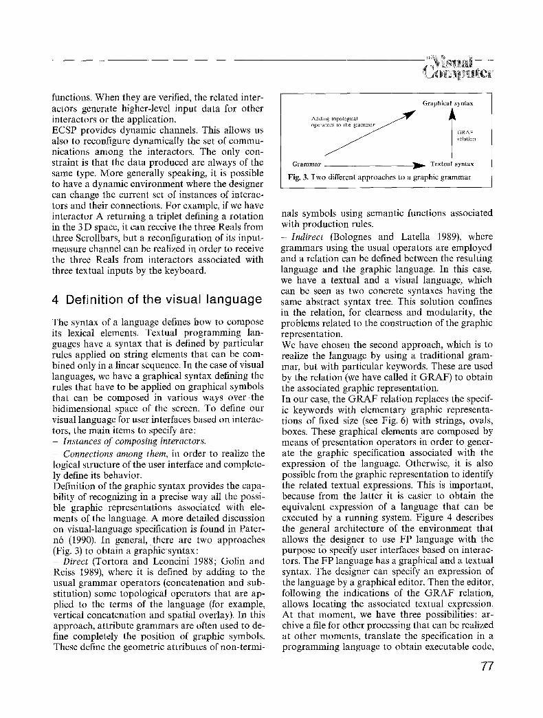
- Connec t ions among them, in order to realize the logical structure of the user interface and complete- ly define its behavior. Definition of the graphic syntax provides the capa- bility of recognizing in a precise way all the possi- ble graphic representations associated with ele- ments of the language. A more detailed discussion on visual-language specification is found in Pater- n6 (1990). In general, there are two approaches (Fig. 3) to obtain a graphic syntax:
Direc t (Tortora and Leoncini 1988; Golin and Reiss 1989), where it is defined by adding to the usual grammar operators (concatenation and sub- stitution) some topological operators that are ap- plied to the terms of the language (for example, vertical concatenation and spatial overlay). In this approach, attribute grammars are often used to de- fine completely the position of graphic symbols. These define the geometric attributes of non-termi-
Graphical syntax
2dedr Jan g topological ~ 1~ I GRAF relation
Grammar ~ Textual syntax
Fig. 3. Two different approaches to a graphic g rammar
nals symbols using semantic functions associated with production rules. - I n d i r e c t (Bolognes and Latella 1989), where grammars using the usual operators are employed and a relation can be defined between the resulting language and the graphic language. In this case, we have a textual and a visual language, which can be seen as two concrete syntaxes having the same abstract syntax tree. This solution confines in the relation, for clearness and modularity, the problems related to the construction of the graphic representation. We have chosen the second approach, which is to realize the language by using a traditional gram- mar, but with particular keywords. These are used by the relation (we have called it GRAF) to obtain the associated graphic representation. In our case, the GRAF relation replaces the specif- ic keywords with elementary graphic representa- tions of fixed size (see Fig. 6) with strings, ovals, boxes. These graphical elements are composed by means of presentation operators in order to gener- ate the graphic specification associated with the expression of the language. Otherwise, it is also possible from the graphic representation to identify the related textual expressions. This is important, because from the latter it is easier to obtain the equivalent expression of a language that can be executed by a running system. Figure 4 describes the general architecture of the environment that allows the designer to use FP language with the purpose to specify user interfaces based on interac- tors. The FP language has a graphical and a textual syntax. The designer can specify an expression of the language by a graphical editor. Then the editor, following the indications of the GRAF relation, allows locating the associated textual expression. At that moment, we have three possibilities: ar- chive a file for other processing that can be realized at other moments, translate the specification in a programming language to obtain executable code,
77

/ \ language (Ocearn, C, ...)
L
User interface
Fig. 4. Architecture of the operating environment
and translate the specification in a general-purpose formal notation (in this way, it is possible to apply on it tools to simulate the specification and investi- gate the associated properties). From the specifica- tion in a formal notation by a specific available tool, it is possible to translate directly in a pro- gramming language. When the specification of a user interface is defined in a formal notation, it is possible to apply some tools, other than to verify its correctness, to investi- gate if properties, such as deadlock-free and equiv- alences, are verified and to simulate its dynamic behavior. Then the specification may be refined in a programming language to obtain the executable system. The external appearance of each interactor at run-time is defined by a set of default values or by primitives provided by the application. It can be modified during the execution by receiving new data from application processes or from other interactors into the related collection. By defining different relations between the textual and the graphical syntax, it is possible to obtain different graphic representations for the same lan- guage. This provides the designer with one of many choices, depending on his requirements, skill, or tastes. For example, in our case it is possible to indicate the partner process over a channel by a pop-up menu, which visualizes its identifier at the click of the mouse on the channel representation or by a straight segment connecting the representa- tion of the two communicating interactors. The first choice is better suited when there are too many graphic items and the set of lines is very complex and difficult to interpret. The graphic specification is realized by a syntax- driven editor. It allows the designer to select inter- actor instances and their parameters choosing
78
among a set of possibilities. For each type of choice, it is possible to define new possibilities. One of the advantages of a syntax-driven editor is that the designer is guided during the specification, and it is possible to immediately check for syntactical errors. For example, if it is specified that the value produced by an interactor has to be sent to another one and the latter does not have that data type among its input data types, an error will be sig- naled. Obviously, lexical errors are prevented by selecting an item by pointing instead of by typ- ing. The grammer rules in Fig. 5 show that in the FP language a user interface is seen as an identifier and a list of interactors. Each interactor has an identifier and a category. Depending on the catego- ry chosen, there are different definitions, because each category has a different set of channels to communicate with the outside. Once the communi- cation channels are defined indicating the partner processes and associated data types, logical con- nections among interactors are also recognized and the structure of the user interface is finally speci- fied. In Fig. 6, some rules used by the relation are pre- sented to expand the expressions of the graphic language in the graphic space. This is done by using some presentation operators (such as inside and
G r a p h i c a l g r a m m a r rules to de f ine a u s e r i n t e r f a c e
<user interface> = OUl ( <interface id>, <list mteractor>)
<hst_interactor> = <interactor> I <interactor> <list interactor>
<interactor> = GINT(<interactor_id>, <int_category_id>) I <device>
<int_category_id> = <inputcategory> I <output_category> I <input_output category>
<input category> = GlNTI(<int class>, <ch_as>, <ch_ss>, <oh_as>, <ch_as>)
<ouput_category> - GINTO(<int_class>, <ch_ss>, <ch as>, <oh ss>)
<input output_category - GINTIO(<int_class>, <ch_ss>, <ch as>, <ch ss>, <ch as>, <ch_as>, <ch_ss>)
<device> ~ <device type> <interactor_id>
<device_type> = <input_device> [ <ouput_device>
<input_device> = <physicalinput_devlce> <ch_ss>
<outputdevice> = <phisical_output_device> <ch_as>
<physical input_device> = MOUSE ] KEYBOARD I ""
<physical ouput device> SCREEN [ ...
<ch_ss> = SA(<proeess id>, <ch_data type>, <process_id>)
<ch as> = LA(<list j~rocess_id>, <ch_data type>, <process id>)
<oh so> = QA(<process_id>, <chda ta type>, <process_id>, <int_exp>)
<int_class> = Integer I Position I Real I String I Null I ...
<ch data type> = <output~primitive> ] <control_request> I <input~rimitive>l .-
F i g . 5. User interface grammar

og lpg: er
G R A F c o m p o s i t e s y m b o l s
GUI - box upside(identifier) inside (list_of_GINT)
list of GINT = GINT ] GINT list of_GINT ] <device> iist of GINT [ <device>
GINT ~ box inside (oval inside(identifier))
GINTI = aslde_(4)~ooints(LA versus(in), SA versus(out)
LA versus(in), LA versus(in)), center (int class)
GINTIO = aslde ( 6 ) ~ o i n t s ( g A versus(in), LA versus(in), SA versus(out)
LA versus(in), LA versus(in), SA versus(out)), center (int_class)
GINTO = as ide_(3 )~o in t s (SA versus(in), L A versus(in)
SA versus(out)), center (iiat class)
SA - arrow popup(identlf ier , idendfier ,ch_data type)
L A - large_arrow popup(identifier_iist, ident i f ier ,chdata_type)
QA - arrow pepup(identifier, identlfier,ch_data type) up(queue)
Fig. 6. Example of the GRAF relation
upside) applied on the alphabet of previously de- fined elementary graphics symbols with fixed size (such as box and oval). The operators indicate some constraints related to the position of symbols that have to be verified among the symbols of the graphic representation. For example, the represen- tation of an interactor is composed of a box inside an oval, which contains the name of its identifier and its class. The representations of the channels are placed on some previously defined point, de- pending on the interactor category. They are differ- ently shaped arrows, depending on the protocol used and on the direction of the data flow.
5 Graphical environment
sentations of the available categories of interactors and the indication of the set of commands to con- tinue his work (Fig. 7). It is possible to create and destroy instances of interactors. A better methodology for building a graphic envi- ronment to describe the structure of the user inter- face is to place in the lower side of the graphic space those interactors associated with physical de- vices, then those connected with them, and so on up to the higher side of the graphic space. In creating one instance of interactor, the designer first indicates its category by selecting the associat- ed graphical representation. Then the icon asso- ciated with the selected category (in the Command Area) is substituted by a sequence of menus allow- ing the designer to select the values for each inter- actor parameter: first, the class (data type produced by the interactor), then the subclass (set of input data types for trigger and for measure), and finally the trigger and measure functions defined by com- posing different kinds of available operators (logi- cal, temporal, and numerical). The user-interface designer indicates them by pointing on a menu list- ing the representations of the available ones. At the moment of specifying the input function, the set of data types previously selected in defining sub- class appear. The designer must indicate in which order to apply the selected operators to the selected data types. If the editor does not detect any mis- take, such as class not corresponding to the data type delivered by the measure function, the func- tion is stored in the definition of the interactor. A typical example of an input measure is a function that delivers an object identifier depending on the value of a position received as input.
After having defined the visual language, we have also realized a tool to provide a more friendly envi- ronment to specify the logical structure of user in- terfaces. We have added new functions other than the specification of a visual program. The functions supported are described below.
Modify the instances of interactors
When the designer begins his work session, he must indicate if he wants to create a new interface or modify one previously defined. Then he can work on windows divided into two areas: a Work Area containing the results of the designer choices, and a Command Area containing the graphical repre-
Edit the connections
When this option is chosen, the editor asks a per- son to select in the Work Area the interactor whose connections have to be defined. After its selection, it asks the designer to indicate which interactors send input for the measure and trigger functions of the selected interactor and to which interactor to send the produced output picture. The designer can change the logical structure of the user inter- face changing the communication channels either because the set of existing interactors has changed or because he wants to modify the possible data paths. This is obtained by means of the capabilities of the underling support of ECSP that allows modi-
79
fying the sender processes of each channel. Connec- tions are stored in the editor system so that succes- sively related requests can be answered.
Visualize the connections
available interactors can be useful. In this way, only a subset of allocated instances can receive, elabo- rate, and send data. The deactivated interactor highlights their state to the user by blinking their graphic representation.
In normal operations, the connections are not graphically represented in order to avoid having too complex and difficult-to-understand represen- tations of the user interface. At any time, it is possi- ble to require each interactor to visualize the corre- sponding connections. This is realized by selecting the View Connections command. Then the editor asks the designer to select an interactor. A double button appears to allow the designer to indicate if the connections of the selected interactor should be visualized in a simple or complex way. In the first case, the lines connecting the graphic represen- tation of the selected interactor with those com- municating with it are shown. In the complex way, it is possible to visualize the entire graph represent- ing the connections between the selected interactor and the others, and then, recursively, those of the connected interactors. In this way, it is possible to see all the interaction paths arriving to that in- teractor and leaving from the physical devices.
S a v e for further elaborations
It is possible to save the specification of a user interface to process it again later. The associated textual specification of the expression of the graph- ic language is saved with an identifier name indicat- ed by the designer. When it is selected for further manipulation, it is interpreted by the GRAF rela- tion to obtain again the associated graphic repre- sentation.
Visual ize the current values of a interactor
You can select an interactor to visualize the current values of the parameters describing its behavior. These appear by pop-up menus.
Selec t an act ivat ion or deact iva t ion status
In complex user interfaces or in the prototypation phase, the capability to activate only part of the
6 Example
In this example, the logical structure of a composed interaction is specified using eight interactors: six of input category, one of input/output category, and one of output category which are layered in three levels (one associated with the physical de- vices, one with the input interactors, and one with the I/O interactor). They are composed to realize the following composed interaction: the user can provide via keyboard three Reals (each one pro- duced by the internal behavior of a specific interac- tor), allowing him to indicate a rotation in 3D. He can also select a visualized object via the mouse. The object identifier (an integer) and the three Reals can be sent to an I/O interactor that pro- duces, as result of the external behavior, the se- lected object rotated by the specified value. The result is sent to the screen. The I/O interactor com- putes the rotated object when its trigger is verified. In our example, it receives input to the trigger from the interactor producing the object identifier. This means that each time it receives a new object iden- tifier it produces its rotated representation, while each time it receives new rotation coefficients these are stored to be applied when the trigger is verified. If the three Reals also were sent as input to the trigger function of the I/O interactor, its behavior would be modified, because the trigger also would be verified for each new rotation coefficient. This would mean that the last-selected object is rotated each time a rotation coefficient is modified. At the beginning, the designer starts the Interactors Editor, whose initial layout is shown in Fig. 7. It is divided into the Work Area and the Command Area with commands and the graphic representa- tion of available interactors categories. At the be- ginning, the designer must indicate which physical devices his user interface will use. Then he starts to create instances of interactors. This means that he firstly selects the associated category and then a list of menus appears asking a person to indicate the input data types for the measure and trigger functions. Then the related processing has to be defined. The lists of available operators input data
80

e
Interactors Editor
I~TEP&CTOR
CATEGORIES
D
CLEAR VIEN AREA
MOVE
VIE~I C0}~[ECTIONS
EDITING CO~ECTIO~S
DESTROY
7
[ ] ................................................................................................................................... Interactors Editor -~
�9
I I I l T E R A C T O R
CATE~RIES
~ L E ~ I VIE~ ~REA
M O V E
~IEM CONNECTIONS
EDITING CONIIECTIOHS
DESTROY
..... S~VE . . . . . . . . . . . . . . . .
N fgt-g;;~to?~-~2~g? . . . . . . . . . . . . . . . . . . . . . . . . . . . . . . . . . . . . . . . . . . . . . . . . . . . . . . . . . . . . . . . . . . . . . . . . . . . . . . . . . . . . . . . . . . . . . . . . . . . . . . . . . .
�9
�9
|
INTERACTOR
CATEGORIES
ILEAR VIEN AREA
VIEW CO~B~CTIO~IS
EDITING COIlI~CTIO~S
DESTROY
SA~
Fig. 7. Initial layout of the Interactors Editor
Fig. 8. Instances of interactors
Fig. 9. Extended visualization of connections for an interactor
81

types previously selected appear. Then the designer defines the function by indicating how the opera- tors he selects should be applied to the data types. Once the interactor instance is completely defined, its graphical representation (indicating category, class and identifier) can be placed in the Work Area. After having defined the instances of interactors (Fig. 8) composing the User Interface System, the designer must indicate how they are connected. This means selecting the Editing Connections op- tion. The editor asks a person to select an interac- tot instance and indicate from which interactor it receives input to the measure and trigger functions and, if it has also output functionality, to which interactor to send the resulting external behavior of the current interactor. After defining the connec- tions, they are not immediately visualized. The de- signer can ask the editor to visualize or to make invisible the connections in a flexible way. In Fig. 9 all the connections belonging to communication paths passing through Interactor 7 are visualized:
7 Conclusions
The examined approach provides a way to define the logical structure of user interfaces based on interactors. The designer of the user interface can realize it in a simple way using direct-manipulation techniques. It is possible to check the presence of mistakes in the specification as soon as it is rea- lized, because the tool knows the rules specifying the language and communicates the detected mis- takes immediately to the designer. The result of the graphical specification is a compact representa- tion of the interacting objects composing the user interface and their relationships. This can be very useful for the designer to quickly understand the processing accomplished by the user interface to realize its internal and external behavior. Before refining the user interface specification in a programming language, it is possible to apply specific tools to investigate its properties (Patern6 and Faconti 1991). For example, it is possible to check if all interactors are crossed by a path be- tween user and application and if there are possible deadlock situations. In this way, we have a visual language to develop unser interfaces that provides the designer with an extensible and flexible set of functions. This is very important, because it makes it easier to realize a
user interface with the preferred interaction style. This approach provides software reusability, be- cause it is easy to create libraries with typical com- plex interactions defined by a specific set of interac- tors. When these are useful, it is sufficient to con- nect the other interactors of the user interface with their external channels, without defining them again. Future developments of this work are to make it possible to access and manipulate directly the data stored in each collection by dedicated tools that are already developed for particular environments (Howard 1990) and extend the visual language to indicate dynamic conditions for activating/deacti- vating interactors. We are moving the obtained specification from a set of modules implemented with the ECSP notation to a set of LOTOS mod- ules, because for specifications realized in this for- mal notation more flexible and powerful tools are available to investigate the behavior of the realized specifications. We also want a better implementation on a multi- processor architecture. A user interface can be composed of numerous interactors. Each interactor consists of different functionalities. It is an autono- mous entity that executes in parallel with respect to others. This higher architectural parallelism im- proves the performance of user interfaces if it is implemented on a parallel with respect to others. This higher architectural parallelism improves the performance of user interfaces if it is implemented on a parallel system closely related to the graphical hardware. Now they are implemented on a high- resolution workstation with a set of transputers on board where the interactors, implemented by Occam, can be executed.
References
Bajardi F, Vanneschi M (1985) Linguaggi per la programma- zione concorrente. Franco Angeli Libri, Milan
Bass L, Coutaz J (t991) Developing software for the user inter- face. Addison Wesley
Bolognesi T, Latella D (1989) Techniques for the formal defini- tion of the G-LOTOS syntax. Proc IEEE Workshop on Vi- sual Languages
Cardelli L, Pike R (1985) Squeak: a language for communicat- ing with mice. ACM Comput Graph 19(3): 199-204
Chang SK (1986) Introduction: visual languages and iconic lan- guages. In: Chang SK, Ichiwata T (eds) Visual languages. Plenum Press, Ligomenides, PA, pp 1-7
Duce DA, van Liere R, Ten Hagen PJW (1990) An approach to hierarchical input devices. Comput Graph Forum 9(1):15-26
82

Duce D, Hopgood F, Gomez R, Lee J (1991) User interface management and design. Springer Verlag, Berlin Heidelberg New York
Faconti GP, Patern6 F (1989) An approach to the formal speci- fication of the components of an interaction. Proc EURO- GRAPHICS '90
Golin EJ, Reiss SP (1989) The specification of visual language syntax. Proc IEEE Workshop on Visual Languages
Haeberly PE (1988) ConMan: a visual programming language for interactive graphics. Comput Graph 22 (4): 103-111
Hill RH (1986) Supporting, concurrency, communication, and synchronization in human-computer interaction - the Sassa- fras UIMS. ACM Trans Graph 5(3): 179-210
Hoare CAR (1985) Communicating sequential processes. Prentice-Hall International, London
Howard TLJ (1990) A structure network visualiser for PHIGS. Comput Graph Forum 9(2): 139-147
Jacob RJK (1986) A visual programming environment for de- signing user interfaces. In: Chang SK, Ichiwata T (eds) Visu- al languages. Plenum Press, Ligomenides, PA, pp 87-107
Myers B (1990) Taxonomies of visual programming and pro- gram visualization. J Visual Programming and Languages 1 (1):97-123
Myers B (1989) Encapsulating interactive behaviours. Proc CHI Conf'89, pp 117 123
Patern6 F (1990) A comparison of approaches to the formal specification of visual languages, CNUCE Internal report
Patern6 F, Faconti GP (1991) Toward the definition of proper- ties of user interface systems. CNUCE Internal report
Shu N (1985) Visual programming. Van Nostrand Reinhold Singh G (1990) Vu: visual user-interface design. The Visual
Computer 6 (4): 230-241 Tortora G, Leoncini P (1988) A model for the specification
and interpretation of visual languages. Proc IEEE Work- shop on Visual Languages
GIORGIO P. FACONTI is Se- nior Researcher at the National Research Council of Italy Isti- tuto CNUCE, where he pre- sently acts as the head of the Department of Architecture of Software and Hardware Sys- tems and as the CNR represent- tive for Computer Graphics and Human Computer Interaction to the European Research Con- sortium for Informatics and Mathematics (ERCIM). He ob- tained his M.S. in Mechanical Engineering and his Ph.D. in Computer Science from the
University of Pisa respectively in 1971 and 1974. He has been involved in Computer Graphics since 1974 both in industries and research institutions. He has been involved in the process of standardization in Computer Graphics from 1984 and is actu- ally the head of the Italian delegation at ISO IEC/JTC 1/SC 24, where he is involved in the Computer Graphics Reference Model Work Item. His main area of research is on Formal Specification and on Architectures for Interactive Systems, and on Visual Languages.
FABIO PATERN6 received his Laurea degree in Computer Sci- ence at the University of Pisa in 1984. In 1986 he joined CNUCE where he worked in the design of graphics systems. In 1991 he was visiting scientist at the Rutherford Appleton Laboratory, Oxford, where he worked in the field of Formal Methods in Computer Graph- ics. His recent interests include Visual Languages, Formal Methods for Interactive Sys- tems, Design of Graphical User Interface Systems. He is member of ACM, EG, AICA.
83


![Phytochromes and Phytochrome Interacting Factors1[OPEN] · Update on Phytochromes and Phytochrome Interacting Factors Phytochromes and Phytochrome Interacting Factors1[OPEN] Vinh](https://img.dokumen.tips/doc/110x75/5e9224c5cbd0a85457462c45/phytochromes-and-phytochrome-interacting-factors1open-update-on-phytochromes-and.jpg)