Embed Size (px)
Citation preview
A Unified Approach for the Local Buckling Of Sandwich Panels and Trapezoidal Sheeting
Misiek, T. Karlsruhe Institute of Technology, Karlsruhe, Germany
(email: [email protected]) Hassinen, P.
Faculty of Engineering and Architecture, Helsinki University of Technology, Espoo, Finland and Pontek Consulting Engineers Ltd, Espoo, Finland
(email: [email protected])
Abstract
Failure of thin-walled building components like sandwich panels or trapezoidal sheeting is normally initiated through a local buckling of the plane elements of the cross-section. For trapezoidal sheeting, EN 1993-1-3 gives an equation for the determination of the effective width of these plane elements and thus for the calculation of the load-bearing capacity of these components. The cross-sectional parts of a lightly or strongly profiled facing of a sandwich panel can be regarded as elastically supported plane elements, whereas the elastic support is provided by the core material. For the determination of the load-bearing resistance of sandwich panels with lightly or strongly profiled facings, a calculation procedure to determine the effective width of the elastically supported plane elements is needed. Some approaches for the calculation of the effective width already exist. The papers published so far are using a modified buckling coefficient for the calculation of the buckling strength, following Winter’s approach such as given in EN 1993-1-3. Because no generally accepted design procedures exist, the load-bearing resistance of sandwich panels is determined experimentally. Based on the basic principles of structural stability, the buckling strength of the elastically supported plane element can be calculated, taking into account the material properties of the core material and the associated buckling wavelength for minimum buckling strength. Then the design procedures of EN 1993-1-3 for thin plate buckling of trapezoidal sheeting can be used, expanded by the procedures of EN 1993-1-5 for taking into account the column type buckling behaviour for buckling wavelengths smaller than the total width of the plane element. Comparison of the test results with different arrangements to the calculated values shows a good consistency. For lightly profiled faces, depending on the depth of the profiling, failure will finally take place through a plate buckling of the plane elements or by a column buckling of the stiffening profiles, whereas the latter failure mode is looking similar as the wrinkling failure of a flat facing. Comparison of the experimental results obtained with different test arrangements to the calculated values show the present limits of the applicability of the proposed design procedure. The differences in failure modes are discussed.
Keywords: sandwich panels, face layer, buckling, elastic foundation, elastic half-space
14

1. Introduction
The determination of the load-bearing capacity required for the design of sandwich panels is to a large degree based on test results. In contrast, there is a large number of references for the determination of the load-bearing capacity of the trapezoidal sheeting, documented in national standards such as the Swedish StBK-N5 or the German DIN 18807 as well as international standards such as EN 1993-1-3. This is astonishing because both building components are com-parable in materials, geometry and load-bearing behaviour. Compared to trapezoidal sheeting the foam core provides an additional elastic foundation to the plane thin-walled elements.
In the following we will show that the calculation procedures developed for trapezoidal sheeting can be modified to be applied for sandwich panels. This will start with the basic module, of which all cross-sections consist: a simple plane element, like a flange of a strongly profiled face of a sandwich panel.
2. Theoretical background and standardized design procedures
The local buckling of the plane cross-sectional elements shall be taken into account in the determination of the load-bearing capacity of the thin-walled building components. Because of the local buckling of the plates of a medium or high slenderness only an effective width, which is smaller than the total width, can be taken into account.
x
y
a
b
x
zc = f (EC, GC, C)
EIF = f (EF, t, F)
Figure 1: Plate on elastic foundation
The calculation of the effective width is based on the critical buckling stress cr. An additional support provided by an elastic foundation increases the critical buckling stress cr. This increase is an
15

addition to the local buckling stress of the plate without foundation calculated according to EN 1993-1-3. The increase of the critical buckling stress leads to a decrease of the relative slenderness of the plate and thus to an increase of effective width and load-bearing capacity. Up to now, most of the present studies capture the effect of the elastic foundation by adjusting the buckling value k as proposed by Davis, Hakmi and Hassinen (1991). This adjustment is based more on statistical evaluations of test results. The determination of the critical buckling stress can be based on the elastic potential, which is shown in Timoshenko and Woinowsky-Krieger (1959) for the plate without foundation. The calculation of the stiffness of the Winkler’s foundation out of the material parameters EC and GC of the core material is shown in Stamm and Witte (1974). We obtain the following equation:
222
2222
2
22
,
43112
112
bn
am
ma
tE
bn
am
matE
C
CC
C
F
Fpcr
with
CCCC GEE 12
according to Stamm and Witte (1974) to take into account very approximately the anisotropy of the material properties of core materials such as for example polyurethane and polystyrene foam.
The effective width of the plate can be calculated from the critical buckling stress and the relative slenderness. EN 1993-1-3 gives the following expressions:
pcr
yp
f
,
2
, 22,010,1
pp
pp
peff
bb for
673,0673,0
p
p
These equations derived by Winter assume pure plate-like behaviour. This can be found for ratios = a/b > 1,0. Because of the elastic foundation we obtain a buckling wave pattern with an aspect ratio a/b which is smaller than 1,0. This has to be taken into account when calculating the critical buckling stress, leading to an increase of the buckling coefficient k . Unfortunately this also results in a minor support of the mid-part of the plate by the supports at the longitudinal edges compared to buckling patterns with higher aspect ratios. Therefore the load-bearing capacity is lower than the one calculated according to Winter’s equation. Column-like buckling behaviour of the plate has to be taken into account. This can be done by utilising the procedure given in EN 1995-1-5. In this case an interpolation between the plate buckling curve according to Winter and the column buckling curve c
16

is done. This interpolation is based on the ratio of the elastic critical buckling stress of the plate and the column:
ccpc 2
with
0,10 where 1,
,
ccr
pcr
and
ma
tE
amtE C
CC
C
F
Fccr 431
12112
2
2
22
,
ccr
yc
f
,
22,021,015,0 cc
0,1122c
c
3. Comparison with results from numerical calculations and tests with flat plates
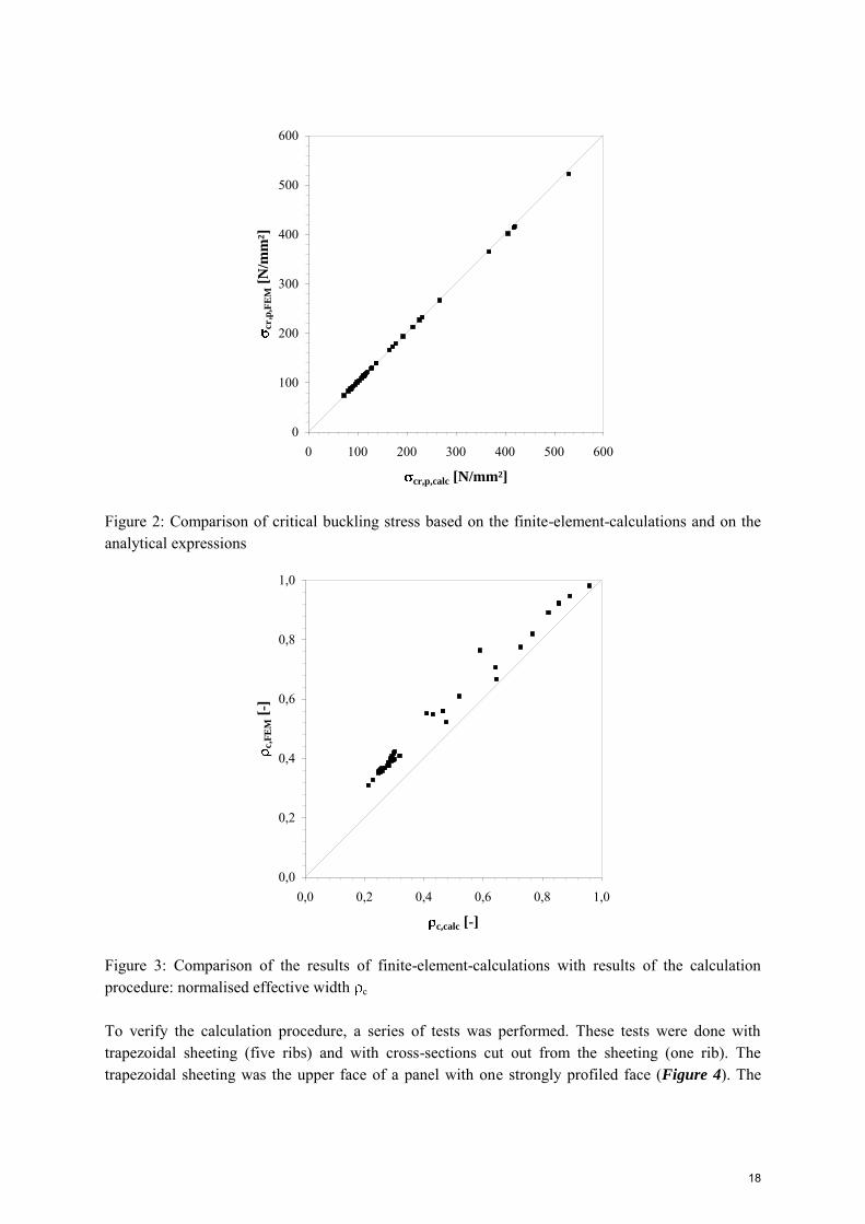
The presented approach for the determination of the load-bearing resistance of a flat plate on an elastic foundation was verified using finite-element-calculations and comparisons with test results. The plates were modelled using four-node shell elements with a linear-elastic ideal-plastic stress-strain relationship. For the elastic foundation, spring elements with a linear elastic stress-strain relationship were used. The parameters such as sheet thickness t, yield strength fy and stiffness of the foundation c (via EC, GC and C) were varied. Figure 2 shows the results of the comparison between the theoretically derived critical buckling stress and the buckling stress based on FE-calculations. Using this FE-model and the initial imperfection corresponding to the first eigenvalue of the model, the ultimate load has been computed. The initial imperfection was scaled to w0 = 0,1 t. The comparison of the computed results with the results of the procedure based on the interpolation between the plate buckling curve according to Winter’s equation and the column buckling curve c is shown in Figure 3.
17
0
100
200
300
400
500
600
0 100 200 300 400 500 600
cr,p,calc [N/mm²]
cr,p
,FE
M [
N/m
m²]
Figure 2: Comparison of critical buckling stress based on the finite-element-calculations and on the analytical expressions
0,0
0,2
0,4
0,6
0,8
1,0
0,0 0,2 0,4 0,6 0,8 1,0
c,calc [-]
c,F
EM
[-]
Figure 3: Comparison of the results of finite-element-calculations with results of the calculation procedure: normalised effective width c
To verify the calculation procedure, a series of tests was performed. These tests were done with trapezoidal sheeting (five ribs) and with cross-sections cut out from the sheeting (one rib). The trapezoidal sheeting was the upper face of a panel with one strongly profiled face (Figure 4). The
18
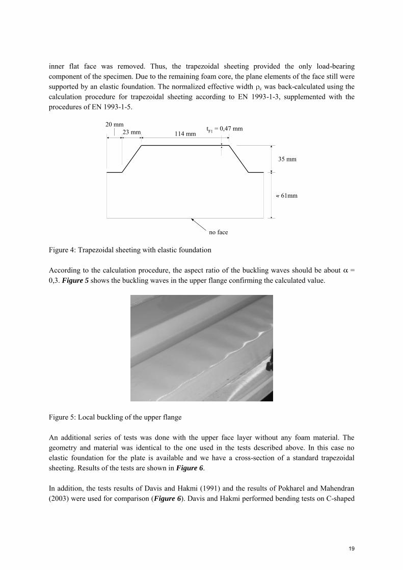
inner flat face was removed. Thus, the trapezoidal sheeting provided the only load-bearing component of the specimen. Due to the remaining foam core, the plane elements of the face still were supported by an elastic foundation. The normalized effective width c was back-calculated using the calculation procedure for trapezoidal sheeting according to EN 1993-1-3, supplemented with the procedures of EN 1993-1-5.
114 mmtF1 = 0,47 mm23 mm
20 mm
no face
35 mm
61mm
Figure 4: Trapezoidal sheeting with elastic foundation
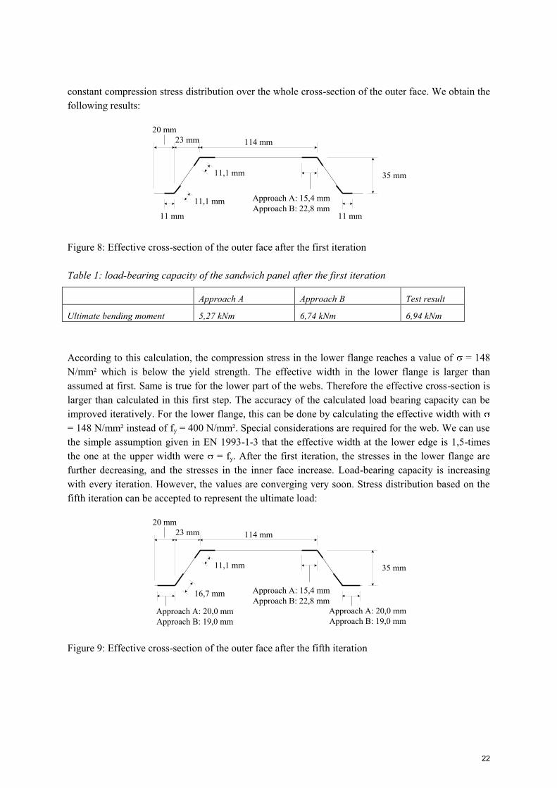
According to the calculation procedure, the aspect ratio of the buckling waves should be about = 0,3. Figure 5 shows the buckling waves in the upper flange confirming the calculated value.
Figure 5: Local buckling of the upper flange
An additional series of tests was done with the upper face layer without any foam material. The geometry and material was identical to the one used in the tests described above. In this case no elastic foundation for the plate is available and we have a cross-section of a standard trapezoidal sheeting. Results of the tests are shown in Figure 6.
In addition, the tests results of Davis and Hakmi (1991) and the results of Pokharel and Mahendran (2003) were used for comparison (Figure 6). Davis and Hakmi performed bending tests on C-shaped
19

members with a foam core. Pokharel and Mahendran glued flat sheets of different thicknesses and steel grades to layers of plastic foam material.
0,0
0,2
0,4
0,6
0,8
1,0
0,0 0,2 0,4 0,6 0,8 1,0
c,calc [-]
c,t
est [
-]
Davis and Hakmi 1991Pokharel and Mahendran 2003trapezoidal sheeting with elastic foundationtrapezoidal sheeting without elastic foundation
Figure 6: Comparison of calculation procedure with test results: normalised effective width c
All the test results show a good correlation with the calculated values. The calculated values make the lower boundary to the test results. Interestingly the values with the highest discrepancy between test and calculation being on the unsafe side are the ones for the standard trapezoidal sheeting without any elastic foundation. This is a result of the very high slenderness of the upper flange, the relative slenderness being of the order of 5,5 to 5,6.
It is interesting to discuss about the effect of the material properties used in the calculation procedure.
The first difference arises in the test method for the determination of the shear modulus GC. Davis and Hakmi performed tests with small cubes of the core material which were loaded with a pure shear load. No information is available about the tests of Pokharel and Mahendran. However, it can be assumed that the tests were done in a similar way based on small cubes. Our tests for the determination of the shear stiffness were performed with small short-spanning beams according to EN 14509. The latter test method might lead to higher discrepancies between the measured value and the actual material properties, resulting in a higher discrepancy between the calculated and experimental values c,calc and c,test.
The elastic modulus EC of the core material is normally determined as an average value corresponding to the total thickness of the specimen, determined separately in a compression and tensile test. For plastic foam materials made in a continuous process the local values strongly deviate from this mean value, depending on the relative position of the sample in the thickness direction of the panel. For these sandwich panels, investigations on the distribution of the stiffness presented in
20

Dürr (2008) show that the elastic modulus near to the faces is higher than in the centre plane of the panel. In addition, different values of the modulus can be obtained close to the faces depending on their position (top or bottom) during the production. These effects have to be kept in mind when looking for the results of our tests (which were done with real panels) and presumably also for the tests of Davies and Hakmi. For the tests of Pokharel and Mahendran which were performed with foam material glued to the face this effect can be neglected. In fact, when calculating the load bearing resistance with the values from the tests, calculated values are on the safe side, because the higher stiffness near the faces gives a stiffer elastic foundation than assumed by using the mean values over the total core thickness.
4. Strongly profiled sandwich panels
In addition to the buckling tests with trapezoidal sheeting, tests with sandwich panels were also performed. The panels had a similar geometry as the specimens introduced before. In these tests, the inner face was not removed, so real sandwich-type load-bearing behaviour existed. The results of the tests were back-calculated, too. Now, the lower flange of the outer face is also under compression loading. This can be easily seen by comparing the pictures of this flange taken after the failure (Figure 7).
Figure 7: Upper and lower flange of the specimens after failure: trapezoidal sheeting with elastic foundation (left) and sandwich panel (right)
The effective cross-section of the outer face can be calculated with the introduced procedure. At first, the effective cross-section of the outer face under compression has to be determined by strictly following the calculation procedure introduced in chapter 2 (approach A). In fact, there will be always a difference between the calculated effective width and the test results. These differences in the determination of the effective width will cause further differences in the calculation of the load-bearing capacity of the sandwich cross-section. In our case, we have also the possibility to use the effective width of the upper flange from the tests on tests described in chapter 3 (approach B) to minimize the effect of the former differences. The use of both the both approaches allows us to compare the results. The calculation has to be done iteratively. For the first iteration we assume a
21
constant compression stress distribution over the whole cross-section of the outer face. We obtain the following results:
114 mm23 mm20 mm
35 mm11,1 mm
11,1 mm
11 mm
Approach A: 15,4 mmApproach B: 22,8 mm
11 mm
Figure 8: Effective cross-section of the outer face after the first iteration
Table 1: load-bearing capacity of the sandwich panel after the first iteration
Approach A Approach B Test result
Ultimate bending moment 5,27 kNm 6,74 kNm 6,94 kNm
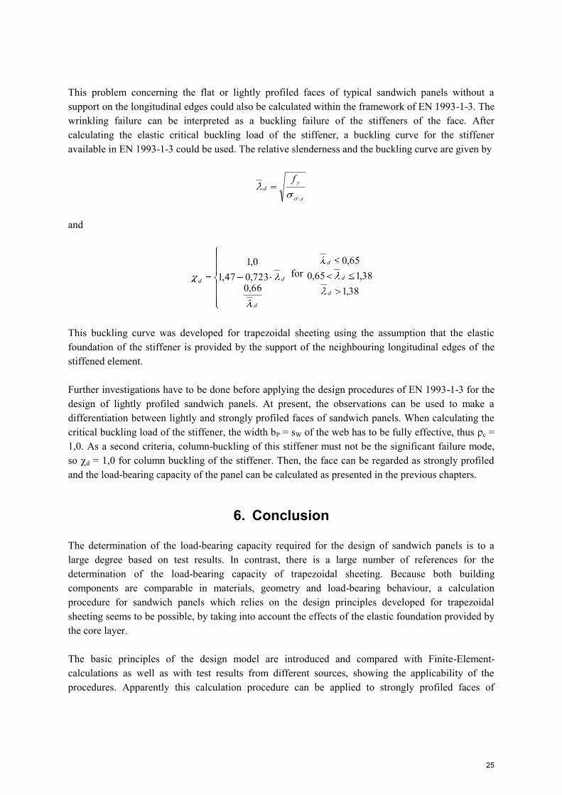
According to this calculation, the compression stress in the lower flange reaches a value of = 148 N/mm² which is below the yield strength. The effective width in the lower flange is larger than assumed at first. Same is true for the lower part of the webs. Therefore the effective cross-section is larger than calculated in this first step. The accuracy of the calculated load bearing capacity can be improved iteratively. For the lower flange, this can be done by calculating the effective width with = 148 N/mm² instead of fy = 400 N/mm². Special considerations are required for the web. We can use the simple assumption given in EN 1993-1-3 that the effective width at the lower edge is 1,5-times the one at the upper width were = fy. After the first iteration, the stresses in the lower flange are further decreasing, and the stresses in the inner face increase. Load-bearing capacity is increasing with every iteration. However, the values are converging very soon. Stress distribution based on the fifth iteration can be accepted to represent the ultimate load:
114 mm23 mm20 mm
35 mm11,1 mm
16,7 mm Approach A: 15,4 mmApproach B: 22,8 mm
Approach A: 20,0 mmApproach B: 19,0 mm
Approach A: 20,0 mmApproach B: 19,0 mm
Figure 9: Effective cross-section of the outer face after the fifth iteration
22

Table 2: Load-bearing capacity after five iterations
Approach A Approach B Test result
Ultimate bending moment 5,94 kNm 7,14 kNm 6,94 kNm
This is a considerable improvement compared to the results of the first iteration. However, in the example we have a difference between the values of the pure calculational approach A and the test result. The difference is in the same order as for the simple flat plate element.
5. Resistance of lightly profiled faces
A local buckling phenomena can also be observed in tests with panels having a slightly profiled face. Figure 10 shows the face of a lightly profiled sandwich panel (depth of lining approx. 2,0 to 2,5 mm) in a bending test before reaching the failure load. Finally, failure will occur by global buckling or wrinkling of the face over the complete width of the panel, depending on the support conditions at the longitudinal edges of the compressed face.
Figure 10: Local buckling of the slightly profiled face of a sandwich panel
For an extension of our approach to lightly profiled faces on an elastic support, the results of the buckling tests of Pokharel and Mahendran (2005) were used. Pokharel and Mahendran (2005) varied the thickness of the faces and the width b of the plane elements of the profiling. The total dimensions of the faces were 400 mm and 1200 mm in the width and length directions, respectively. All the edges were fully supported. The effective width of the plane elements between the stiffeners can be calculated according to the presented calculation procedure. After incorporating the restrictions in EN 1993-1-3 requiring some reductions in width also the cross-sectional values of the stiffeners itself can be calculated. The part of the critical buckling stress provided by the stiffeners can now be calculated using
23

32, 8,1e
sscr bb
tIE
Assuming a global buckling failure of the stiffened plate and recalculating the tests with the equations introduced in section 2 of this paper, the results shown in Figure 11 were obtained.
0,0
8,0
16,0
24,0
32,0
40,0
0,0 8,0 16,0 24,0 32,0 40,0
Nu,calc [kN]
Nu
,test [
kN
]
b = 78,5 mmb = 28,5 mm
b13 mm4,25 mm 4,25 mm
1,0 mm
Figure 11: Comparison of results of calculation procedure with test results
It can be shown that for the geometry investigated in Pokharel and Mahendran (2005) the effects of the stiffeners can be neglected and the support at the longitudinal edges as well as the elastic foundation of the core material are the dominating stabilising effect. In this case, failure occurred by local buckling of the entire stiffened plate. The overall width dominated against the width of the lining between the stiffeners.
Typical flat or lightly profiled faces of sandwich panels do not have supports at the longitudinal edges. The wrinkling stress of these panels is usually calculated using the so-called Plantema-equation.
282,0 CCFcr GEE
The coefficient 0,82 is in most cases modified to take into account the effects of imperfections etc. By doing so the transition form the elastic critical buckling tress to the ultimate buckling stress is done. Further modifications of this coefficient, sometimes denominated as a wrinkling factor, can be justified by taking into account the geometry of the faces, leading to a value derived from tests. Further adjustments of this equation are discussed in Pokharel and Mahendran (2005).
24
This problem concerning the flat or lightly profiled faces of typical sandwich panels without a support on the longitudinal edges could also be calculated within the framework of EN 1993-1-3. The wrinkling failure can be interpreted as a buckling failure of the stiffeners of the face. After calculating the elastic critical buckling load of the stiffener, a buckling curve for the stiffener available in EN 1993-1-3 could be used. The relative slenderness and the buckling curve are given by
scr
yd
f
,
and
d
dd66,0723,047,10,1
for
38,138,165,0
65,0
d
d
d
This buckling curve was developed for trapezoidal sheeting using the assumption that the elastic foundation of the stiffener is provided by the support of the neighbouring longitudinal edges of the stiffened element.
Further investigations have to be done before applying the design procedures of EN 1993-1-3 for the design of lightly profiled sandwich panels. At present, the observations can be used to make a differentiation between lightly and strongly profiled faces of sandwich panels. When calculating the critical buckling load of the stiffener, the width bP = sW of the web has to be fully effective, thus c = 1,0. As a second criteria, column-buckling of this stiffener must not be the significant failure mode, so d = 1,0 for column buckling of the stiffener. Then, the face can be regarded as strongly profiled and the load-bearing capacity of the panel can be calculated as presented in the previous chapters.
6. Conclusion
The determination of the load-bearing capacity required for the design of sandwich panels is to a large degree based on test results. In contrast, there is a large number of references for the determination of the load-bearing capacity of trapezoidal sheeting. Because both building components are comparable in materials, geometry and load-bearing behaviour, a calculation procedure for sandwich panels which relies on the design principles developed for trapezoidal sheeting seems to be possible, by taking into account the effects of the elastic foundation provided by the core layer.
The basic principles of the design model are introduced and compared with Finite-Element-calculations as well as with test results from different sources, showing the applicability of the procedures. Apparently this calculation procedure can be applied to strongly profiled faces of
25
sandwich panels as well as for trapezoidal sheeting with bonded plastic foam insulation. The last-mentioned building components have found increasing dissemination on the market in the last years.
Finally, an overview to the design of lightly profiled sandwich panels was made. Comparison with test results showed the present limits of the applicability of the design procedures of EN 1993-1-3 if applied to sandwich panels. Lightly profiled faces show a complex behaviour with interactions from plate buckling and column buckling failure. This can not be captured on a sufficient safety level at the moment.
Acknowledgements
ThyssenKrupp Steel Europe AG provided specimens for the experimental investigations. We express our sincere gratitude for this support.
References
Timoshenko S P Woinowsky-Krieger S (1959) Theory of Plates and Shells, New York, McGraw-Hill.
Stamm K and Witte H (1974) Sandwichkonstruktionen: Berechnung, Fertigung, Ausführung, Wien New York, Springer Verlag
Davies M J, Hakmi M R and Hassinen P (1991) “Face buckling stresses in sandwich panels” Contributions 1991 ECCS Nordic Steel Colloquium, p. 99-110.
Davies M J and Hakmi M R (1991) “Postbuckling behaviour of foam-filled thin-walled steel beams” Journal of Constructional Steel Research 20: 75 - 83.
Pokharel N and Mahendran M (2003) “Experimental investigations and design of sandwich panels subject to local buckling effects” Journal of Constructional steel research 59: 1533-1552.
Pokharel N and Mahendran M (2005) “An investigation of lightly profiled sandwich panels subject to local buckling and flexural wrinkling effects” Journal of Constructional steel research 61: 984-1006.
Dürr M (2008) Die Stabilisierung biegedrillknickgefährdeter Träger durch Sandwichelemente und Trapezbleche, Berichte der Versuchsanstalt für Stahl, Holz und Steine der Universität Fridericiana in Karlsruhe, 5. Folge – Heft 17. Karlsruhe 2008.
EN 1993-1-3: Eurocode 3: Design of steel structures – part 1-3: General rules - Supplementary rules for cold-formed members and sheeting
EN 1993-1-5: Eurocode 3: Design of steel structures – part 1-5: Plated structural elements
26


![Buckling Analysis of Aluminum Foam Sandwich Plates and ... · [35] S. Yusuff. Face wrinkling and core strength in sandwich construction. Journal of the Royal Aeronautical Society,](https://img.dokumen.tips/doc/110x75/5bcb8c4509d3f2761f8c3d4c/buckling-analysis-of-aluminum-foam-sandwich-plates-and-35-s-yusuff-face.jpg)


![Finite Element Modeling of the Buckling Response of ...mln/ltrs-pdfs/NASA-aiaa-2002-1517.pdf · Frostig [7] investigated sandwich panel buckling using a higher-order theory which](https://img.dokumen.tips/doc/110x75/5bb925ec09d3f2333b8e1829/finite-element-modeling-of-the-buckling-response-of-mlnltrs-pdfsnasa-aiaa-2002-1517pdf.jpg)