Embed Size (px)
Citation preview
AIAA-2002-1517
Finite Element Modeling of the Buckling Response of Sandwich Panels
Cheryl A. Rose 1
NASA Langley Research Center
Hampton, VA 23681
David F. Moore 2
Lockheed-Martin Engineering and Sciences Company
Hampton, VA 23681
Norman F. Knight, Jr. 3
Veridian Systems Division
Chantilly, VA 20151
Charles C. Rankin 4
Lockheed-Martin Advanced Technology Center
Palo Alto, CA 94304
Abstract
A comparative study of different modeling approaches
for predicting sandwich panel buckling response is
described. The study considers sandwich panels with
anisotropic face sheets and a very thick core. Results
from conventional analytical solutions for sandwich
panel overall buckling and face-sheet-wrinkling type
modes are compared with solutions obtained using
different finite element modeling approaches. Finite
element solutions are obtained using layered shell
element models, with and without transverse shear
flexibility, layered shell/solid element models, with shellelements for the face sheets and solid elements for the
core, and sandwich models using a recently developed
specialty sandwich element. Convergence characteristics
of the shell/solid and sandwich element modeling
approaches with respect to in-plane and through-the-
thickness discretization, are demonstrated. Results of
the study indicate that the specialty sandwich element
provides an accurate and effective modeling approach
for predicting both overall and localized sandwich panel
buckling response. Furthermore, results indicate that
anisotropy of the face sheets, along with the ratio of
principle elastic moduli, affect the buckling response
and these effects may not be represented accurately by
analytical solutions. Modeling recommendations are
also provided.
Introduction
The increased performance requirements of future
aeronautical and aerospace vehicles, and the projected
increased demand for air travel, suggest that more
efficient aeronautical and aerospace flight vehicle
concepts are needed. An example of a revolutionary
concept for an efficient, large transport aircraft is a
blended-wing-body type (BWB) of aircraft, which
blends the wings and fuselage into a single lifting
surface. Due to the shape of the BWB airplane, the
pressurized centerbody region, which includes both the
passenger area and the cargo area, is non-circular. The
1Aerospace Engineer, Mechanics and Durability Branch. Member AIAA.
2Aerospace Engineer. Member ASME.s Staff Scientist. Associate Fellow AIAA. Member ASME. Corresponding author.4Staff Scientist. Associate FellowAIAA.
Copyright ©2002 by the American Institute of Aeronantics and Astronautics, Inc. No copyright is asserted in the United States under Title 17, U.S. Code. The U. S. Government has a royalty-free license to exercise all rights under the copyright claimed herein for Governmental Purposes.All other rights are reserved by the copyright owner.
1
American Institute of Aeronautics and Astronautics
https://ntrs.nasa.gov/search.jsp?R=20030005448 2018-08-18T04:32:43+00:00Z

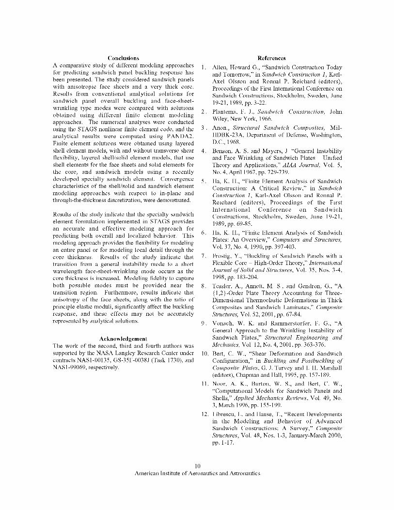
non-circularcenterbodyregionischallengingfromthestandpointof structuraldesignsincethebasiccoverpanelstructurecarriesbothinternaltransversepressureloadandnormalwingbendingandtorsionloads.Inorder to satisfy the performanceand weightrequirementsfortheBWBaircraft,andotheradvancedconceptsthataresubjectedto bendingor pressureloadings,advancedsandwich-typeconstructionswithcompositematerialfacesheetsandrelativelythickcores(seeFigure1)offerapotentialdesignadvantageoverconventionalmetallicmaterialsandstiffenedskinconstruction[1].
Mostsandwichstructuresaredefinedusingathree-layertypeof construction,asillustratedin Figure1. Theouterlayersarethin,stifthigh-strengthmaterial;whilethemiddlelayerisathick,weak,low-densitymaterial.Initialanalyticalworkonsandwichstructurestreatedthethree-dimensionalsandwichstructureasa pair ofmembranefacesheetsheldapartbyacorematerialwitharelativelylargetransverseshearstiffness.Thebendingstiffnessof thefacesheetsis ignoredandthecoreisassumedtobeinextensionalinthetransversedirectionandhasnegligiblestiffnessin thein-planedirections.Thistypeofmodel,calledasandwichofthefirstkind,hasbeenappliedsuccessfullyin manyapplications.However,a morerobustformulationwithadditionalfidelityisneededtomodelcomplexnonlinearstructuralbehaviorincludinglocalfailuressuchasface-sheetbucklingandface-sheetdisbond.A sandwichof thesecondkindaccountsfortheout-of-planeresponseofthefacesheetsandthefullthree-dimensionalbehaviorofthecorematerial.
EarlyanalysisworkformetallicsandwichstructuresincludesPlantema[2], anddesignguidelinesforsandwichstructuresaregivenin Ref.[3]. Generalinstabilityandface-sheetwrinklingaredescribedbyBensonandMayers[4]. Oneaspectoftheirworkwasrelatedto definingastabilityboundarybetweenface-sheetwrinklingandgeneralinstability.Researchershavealsostudiedtheanalysisof sandwichstructureswithemphasisontheuseof compositematerialfacesheetsandfoamcores.Finiteelementformulationsforsandwichpanelsare reviewedby Ha [5, 6].Displacement-basedformulationsand hybridformulationsareconsideredaswellasdifferentthrough-the-thicknesskinematicmodels.Nonumericalstudiesarepresented.Frostig[7] investigatedsandwichpanelbucklingusingahigher-ordertheorywhichaccountsfordifferentboundaryconditionsontheupperandlowerfacesheets.Usingaclosed-formsolution,hestudiedtheinfluenceonbucklingof differentboundaryconditionsforvariouspanelaspectratiosandforbothsoftandstiffcores.Tessleret al. [8] present a {1,2}-order theory
accounting for transverse shear and normal stresses and
strains. They present linear stress solutions for
thermally loaded, simply supported sandwich plates
with laminated face sheets using an analytic, closed-
form solution. Vonanch and Rammerstorfer [9]
presented a Rayleigh-Ritz solution for face-sheet
wrinkling of general unsymmetric sandwich panels with
orthotropic face sheets. Comparison of their analytical
results with unit-cell three-dimensional finite element
results is used to verify their approach.
Bert [10] summarized different theories for sandwich
plates with laminated composite face sheets that account
for both transverse shear and transverse normal effects.
Noor et al. [11] presented an exhaustive reference list
(over 1300 citations) of analytical and computational
proceduJces for sandwich structures. Librescu and Hause
[12] presented a further survey and extended the
formulation to include buckling and postbuckling
response of flat and curved sandwich structures
subjected to mechanical and thermal loads. A Rayleigh-
Ritz procedure for simply supported sandwich plates
was developed by Rao [13] where the bending stiffness
of the face sheets was ignored. Kim and Hong [14]
extended Rao's work to account for the face-sheet
bending stiffness. Hadi and Matthews [15] presented a
Rayleigh-Ritz procedure based on a zigzag theory andaccounts for shear deformation in the face sheets.
Comparisons with other Rayleigh-Ritz solutions were
presented for sandwich panels with thin face sheets.
Results are reported for different face-sheet stacking
sequences. Dawe and Yuan [16, 17] presented a finite
strip formulation using B-splines for sandwich panels
with anisotropic face sheets. However, no comparative
numerical studies of different finite element modeling
strategies for predicting the buckling response of
sandwich panels have been identified in the literature.
The present paper describes the basic buckling behavior
and response of sandwich panels loaded in axial
compression and compares buckling predictions for
various levels of finite element modeling fidelity.
Buckling results obtained from approximate analytical
expressions are also compared with buckling results
obtained from the finite element analyses. Different
finite element models of the sandwich panel are
considered including layered shell models, specialty
sandwich element models, and layered shell/solid
models. Numerical results obtained using the STAGS
(STructural Analysis of General Shells) nonlinear finite
element code [18] for the three different finite element
modeling approaches are presented for selected
sandwich panel design parameters. Parameters varied in
the study include the face-sheet thickness and the core
thickness as well as modeling fidelity. Particular
attention is given to examining the buckling behavior for
a specific panel aspect ratio, as the core thickness
2
American Institute of Aeronautics and Astronautics
becomeslarge.Theresultspresenteddemonstratetheinterplaybetweenfiniteelementmodelswithdifferentlevelsof fidelityandthemodelingrequirementsforaccuratepredictionof sandwichpanelbucklingresponse.Generalmodelingguidelinesareprovided.
Sandwich Panel Buckling
Sandwich panel buckling involves several possible
modes. Three buckling modes are considered in this
study. One mode is an overall panel buckling mode or
general instability mode where the face sheets and the
core buckle together into long wavelength buckles - long
in the sense that the length of a half-wave is equal to one
of the planar dimensions of the sandwich panel.
Another possible buckling mode consists of short
wavelength buckles where the face sheets and the core
do not exhibit any transverse extension through the
thickness of the sandwich. This mode is a short
wavelength panel-buckling mode, and is commonly
referred to as an asymmetrical wrinkling mode. Another
short wavelength buckling mode is one where the core
material is either stretched or compressed. This mode is
a short wavelength Jitce-sheet-wrinkling mode, and is
referred to as a symmetrical wrinkling mode. Other
sandwich panel failure modes, such as face-sheet
dimpling, core crushing, and face-sheet disbond, are not
included in the present study.
Analytical predictions of overall sandwich panel
buckling often ignore the bending stiflhess of the core
and assume that the core serves primarily to move the
face sheets away from the midsurface of the panel. A
simple approach for predicting overall panel buckling of
a sandwich panel with homogeneous, isotropic face
sheet and core materials loaded by in-plane compression
and with simply supported conditions on all edges is
presented by Brush and Almroth [19]. Vinson [20]
developed an analytical model that includes the effects
of shear deformation for predicting overall panel
buckling of composite sandwich panels with orthotropic
face sheets. This model, incorporated into PANDA2
[21], is used herein as the analytical model for general
instability and local face-sheet wrinkling predictions.
Buckling loads for general and face-sheet-wrinkling
instabilities are computed for a given sandwich
configuration to determine the minimum buckling load
and the critical buckling mode shape for the sandwich
panel. Parameters having a significant influence on the
buckling response are the face-sheet thickness, tj; thecore thickness, he, and the core shear stiffness, Gc as
well as the panel planar dimensions a and b.
Researchers, such as Allen and Feng [22], have derived
non-dimensional parameters to characterize the
structural response of the sandwich panel. These
parameters can be used to guide an analyst in selecting a
modeling fidelity for sandwich panel buckling analyses.
Finite Element Modeling
Sandwich panel finite element modeling has generally
taken one of three approaches depending on panel
geometry and constituent materials. The buckling
behavior of a sandwich panel is dependent on the
sandwich panel geometry and properties and may
involve a general instability mode, a local instability
mode, or an interaction between the two. Accurate
prediction of general or overall instability modes
requires adequate representation of the sandwich
stiflhesses whereas prediction of local instabilities
requires detailed through-the-thickness modeling. The
first modeling approach exploits standard shell finite
elements. These models are referred to herein as layered
shell models, and for thin sandwich panels may provide
a first approximation of the global behavior. The second
approach uses standard shell finite elements for the face
sheets and solid three-dimensional finite elements for
the core. These models are referred to as layered
shell/solid models and provide a modeling approach for
both general and local response predictions. The
accuracy of this approach, as well as its computational
cost, is related to the through-the-thickness modeling of
the core material. The third approach is a full three-
dimensional finite element model, in which solid three-
dimensional elements are used to model both the face
sheets and the core. These models are referred to as
three-dimensional solid models and they are typically
reserved for detailed local modeling because of their
computational cost. Recently, an additional modeling
approach has been implemented in the STAGS nonlinear
finite element code. This modeling approach, referred to
herein as sandwich element models [18, 23], uses a
specialty element developed specifically for the analysisof sandwich structures. Sandwich element models
embody the kinematics and stiflhess of the sandwich
structure for less computational cost than the layered
shell/solid models. Sandwich element models provide a
cost-effective analysis approach for capturing sandwich
behavior for large-scale sandwich structure simulations
as well as for detailed local analyses. Details for these
modeling approaches are described in the next sections.
Layered Shell Models
Layered shell models exploit the existing plate and shell
finite element analysis features available in most finite
element codes. The sandwich panel is modeled usingtwo-dimensional shell elements with at least three
groups of layers. The first group of layers corresponds
to the laminate of one face sheet. The next group of
layers corresponds to the core material, and the last
group of layers represents the laminate of the other face
3
American Institute of Aeronautics and Astronautics
sheet.Thisapproachgivesanequivalentsingle-layerresultusingclassicallaminationtheorytocomputethesandwichstiffnesscoefficients.Inthismodelalllayershavea common,uniquerotationthroughthecrosssectionof thesandwich.Becausethecorematerialgenerallyonlyoffersshearstiffness,shear-flexibleCoshellelementsaretypicallyusedinlayeredshellmodels.ShellelementsbasedontheclassicalKirchhoff-Lovetheory(C1shellelements)canbeused;however,suchanapproachignoresthetransverseshearflexibilityofferedbythesandwichstructure.WithinSTAGS,the4-nodeC1shellelementiscalledthe410element(see[24])andthe9-nodeANSCoshellelementiscalledthe480element(see[25,26]).Fullintegrationisusedforbothshellelements(i.e.,2x2and3x3,respectively).Finiteelementformulationsforsandwichpanelsbasedonhigh-ordertheories,suchasFrostig[7]andTessleret
al. [8], are not available within STAGS and hence not
included in this study.
Layered Shell/Solid Models
The next level of modeling uses shell elements to model
each individual face sheet and solid elements to model
the core material. These models are referred to herein as
layered shell/solid models. Each face sheet may be a
multi-layer laminate and is modeled using shell
elements, while the core is modeled using solid
elements. Multiple solid elements through the core
thickness may be required to represent the core
deformation accurately. Displacement-field
compatibility between the shell element and the solid
element must be considered during the modeling
process. For example, the use of 4-node C 1 shell
elements for the face sheets with an 8-node solid
element leads to an incompatibility for the normal
displacements. Lagrangian shell elements based on a C o
formulation, used with standard solid elements of the
same order, give displacement-field compatibility for the
translational degrees of freedom. Combinations of the
4-node, 8-node or 9-node C o shell element with the 8-
node, 20-node or 27-node solid element, respectively,
give translational displacement compatibility. Within
STAGS, the compatible set of shell and solid elements
are the 9-node ANS C o shell element (480 element) and
the 27-node ANS C o solid element (883 element). Full
integration is used for both the shell and solid elements
(i.e., 3x3 and 3x3x3, respectively). For the layered
shell/solid models, the shell element reference surface is
defined to coincide with the bounding surface of the
adjacent solid element. In addition, the rotational
degrees of freedom of grid points associated with thecore and not connected to the shell elements of the face
sheets are constrained to zero.
Sandwich Element Models
A specialty finite element for sandwich panel analysis
has been formulated by Riks and Rankin [23] and is
described in the STAGS manual [18]. This specialty
element exploits the existing shell finite element
technology available in the finite element code itself.
The deformation of the face sheets is modeled by using
individual shell elements for each face sheet. Coupling
between the two shell elements is carried out by
applying an appropriate penalty function, consistent with
the material behavior of the core, to enforce the
kinematics of the core as a function of the kinematics of
the face sheets. The core is assumed to have generally
anisotropic three-dimensional elastic properties whose
deformation is defined by the change in distance
between adjacent face sheets. For this special sandwich
element, the face sheets are intrinsically modeled using
the standard STAGS 410 quadrilateral shell elements.
Multiple sandwich elements may be stacked through the
thickness of the core to provide a refined through-the-
thickness discretization of the core material wherein the
intermediate face sheets are treated as "phantom" face
sheets with zero thickness. Between adjacent face
sheets, the transverse shear strain varies linearly with thethickness coordinate and the transverse normal strain is
constant. The number of integration points through thecore thickness of each sandwich element can be chosen
to be either one or two depending on whether a spurious
mode is triggered by the boundary conditions in the face
sheets. Stifler results are generally obtained when two
integration points are used. Within STAGS, this
specialty sandwich element is called the 840 element
[18, 23]. This modeling approach provides a
computationally attractive approach for sandwich panel
analysis for large-scale structures and also provides a
capability to assess detailed response characteristics
using a local strip model.
Numerical Results and Discussion
The basic geometry of the sandwich panels analyzed in
this study is defined in Figure 2. The upper and lower
face sheets are identical. Analytical predictions are
made following the approach of Vinson [20] as
implemented in PANDA2 [21]. Finite element analyses,
using the STAGS nonlinear finite element analysis code
[18], are conducted using layered shell models, layered
shell/solid models, and sandwich element models. The
layered shell models use the 4-node C a 410 shell
element and the 9-node ANS C O 480 shell element. The
finite element approximation for the out-of-plane
displacement is cubic for the 4-node element and
quadratic for the 9-node element. For the layered
shell/solid models, the face sheets are modeled using the9-node ANS 480 shell element and the core is modeled
4
American Institute of Aeronautics and Astronautics
usingthe 27-nodeANS883solidbrickelementsthroughits thickness.Thisapproachprovidesacompatibledisplacementfield betweenthe finiteelementsinthefacesheetsandthoseinthecore.Forthesandwichelementmodels,the840sandwichelements[18,23]areusedthroughthecorethickness.
Fullpanelmodelsaredefinedasfiniteelementmodelsoftheentiresandwichpanel.Spatialdiscretizationofthefull panelis relatedtotheanticipatedbucklingmode.Thus,someknowledgeofthepanelbucklingresponseisneededtodevelopthesefullpanelanalysismodels.Forarectangularpanel,thenumberofhalf-waves,m, along
the panel length in a general-instability panel-buckling
mode is a function of the panel aspect ratio a/b,
assuming a single half-wave across the width of the
panel. Generally, five to six grid points per half-wave
are required for accurate buckling predictions. To
capture a face-sheet-wrinkling mode, the finite element
mesh needs to be sufficiently refined to represent short-
wavelength buckles.
Local strip models are defined as finite element models
of a localized region with significant through-the-
thickness modeling detail so that short wavelength
wrinkling modes can readily be detected. A local strip
model is used to verify short-wavelength face-sheet-
wrinkling behavior predictions obtained with the full
panel models. Local strip models represent a thin
longitudinal slice of a panel away from edge effects. In
the present study this strip model has a width equal to
2.54 mm and has 25 layers of sandwich elements
through the core thickness. One integration point is
used through the thickness of each core layer. The
length of the local strip model depends on the
wavelength of the buckling mode. Therefore, several
local models, with different lengths, are analyzed to
ensure that the lowest buckling load is determined.
Numerical results for two cases are presented. The first
case considers a square sandwich panel with single-layer
orthotropic face sheets and an isotropic core. This case
studies the influence of different modeling approaches
and boundary condition applications on the buckling
response predictions for a given sandwich configuration
loaded in uniaxial compression. The second case
considers a rectangular sandwich panel with isotropic
face sheets and an isotropic core. This case examines
the influence of different modeling approaches on the
buckling response predictions for sandwich panels with
different core thickness and face-sheet thickness.
Case 1: Square Sandwich Panel
Several researchers [13-15, 17] have analyzed the
buckling, under uniaxial compressive stress, of a simply
supported 225-mm square sandwich panel (a/b 1) with
identical single-layer orthotropic face sheets of a given
fiber orientation angle and isotropic core. The face
sheets have thickness tf equal to 0.2 mm and the core has
thickness hc equal to 10 mm (hJa 0.044). The
mechanical properties of the face-sheet material are:
E1 229.0 GPa, E2 13.35 GPa, G12 5.25 GPa and
v12 0.315 (i.e., E2/E1 0.058). Core material data are
given in Table 1. The fiber orientation of the face-sheet
material is varied from zero to ninety degrees where the
zero-degree orientation is parallel to the loading
direction. For fiber orientation angles other than 0- and
90-degrees, the face sheets exhibit anisotropic behavior
and the D16 and D26 bending stiffness terms become
nonzero and large relative to the other bending stiffness
terms. Consequently when the D16 and D26 bending
stiffness terms become nonzero, the buckling mode
shapes may become skewed, relative to the loading axis
with non-straight modal node lines. In addition, as the
face-sheet fiber-angle orientation increases, the number
of half-waves in the general-instability mode increases.
These complexities in the buckling mode shape impose
additional modeling requirements on the analysis
models over those required for the analysis of a panel
without anisotropic effects.
The sandwich panel is loaded by a uniform end
shortening, Uo, applied to the entire loaded edge (Edge 1
or x 0 in Figure 2). The in-plane pre-buckling stress
state has uniform stress in the longitudinal direction, and
the other two in-plane stress components are equal to
zero. To achieve this pre-buckling stress state, the
boundary conditions applied in the finite element
models to all grid points along each edge are:
u=u oandw=O x=Oy=O z=0 along Edge 1 (x 0);
w=0 x=0y=0 z=0 along Edges 2 and 4 (y b and
y 0, respectively); and u w = 0x = 0y = 0 z = 0
along Edge 3 (x a). In addition, a point at the center of
the panel has the transverse displacement v set equal to
zero to remove rigid-body motion. These boundaryconditions result in a uniform stress state in the face
sheets.
Having established a uniform uniaxial stress state,
boundary conditions for the buckling analyses are
defined next. All nodes through the thickness along the
four edges of the sandwich panel are simply supported
for the buckling calculations. These buckling boundary
conditions are:V w = 0_ = 0 along Edges 1 and3
(x 0 andx a, respectively); and, u = w = 0y = 0
along Edges 2 and 4 (y b and y 0, respectively). For
the layered shell modeling approach used in the present
study, these simply supported boundary conditions are
straightforward to impose on the finite element model.
However, for the layered shell/solid modeling approach
5
American Institute of Aeronautics and Astronautics
and the sandwichelementmodelingapproach,independentapproximationsmaybemadefor thebendingrotationsofeachfacesheetandcore.Intheseapproaches,thesimplysupportedboundaryconditionsaredefinedsothatsheardeformationsarepreventedinthecross-sectionalplanesalongthepaneledges[15].Forthe sandwichelementmodelingapproach,thesimplysupportedboundaryconditionsforbucklingmaybeimposedusingrigidlinks(multi-pointconstraints),alongtheboundaries,thattiethelowerfacesheettotheupperfacesheet similartothekinematicsrelationsofclassicalplatetheory whenthepre-stressloadingisanappliedin-planeforceandwhenconstraintsareemployedtoimposeuniformendshortening.Forthebucklingcalculations,thedegreesoffreedomassociatedwiththeend-shorteningresponsearepermittedto befree. Formodelswithmultiplesandwichelementsthroughthe corethickness,boundaryconditionsimposedalongthepaneledgesat intermediateor"phantom"facesheetsarethesameasthoseimposedontheboundingfacesheets.
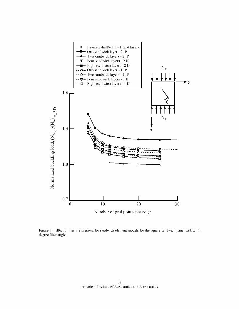
Resultsof a convergencestudyconductedusingthesandwichelementmodelingapproachto predictthebucklingresponseofasquaresandwichpanelwitha30-degreeface-sheetfiberorientationangleareshowninFigure3. Theopensymbolsondashedlinesdenoteresultsobtainedusingmodelswithoneintegrationpoint(IP)throughthethicknessofthesandwichelement,andthefilledsymbolsonsolidlinesdenoteresultsobtainedusingmodelswithtwointegrationpoints.One,two,four,andeightlayersof sandwichelementswereanalyzedformesheswithdifferentlevelsof in-planediscretization.Thepredictedbucklingloadsarenormalizedbythesolutionobtainedusingthelayeredshell/solidapproachwithfoursolidelementsthroughthecorethicknessanda25x25planarmeshof nodes(i.e.,thebucklingloadusedin thenormalizationis340.0N/mm).Thissolutionobtainedusingthehighestfidelitymodelis referredto hereinasthereferencesolutionandisdenotedinFigure3bythe"x" symbolonasolidline.HadiandMatthews[15]reportedavalueof467.8N/mm,andYuanandDawe[17]reportedavalueof 382.6N/mm. HadiandMatthews[15] usedaRayleigh-Ritz solution with trigonometricapproximationsforthein-planevariationandazigzagtheorythroughthethickness.Theirresultsgiveabucklingsolutionstiflerthanthepresentsolutionduetoimplicitboundaryconditionsfromthedisplacementfieldapproximations.YuanandDawe[17]usedafinitestripsolutionwithB-splineapproximationsforthein-plane variationand the through-the-thicknessapproximationsfor the in-planedisplacementsarequadraticandtheout-of-planedisplacementsarelinear.Theirresultsaremuchimprovedduetotheirtreatmentof theboundaryconditions,yetstill stiflerthanthe
presentreferencesolutionthat usesa piecewisequadraticapproximationthroughthecorethickness.
Thepredictedbucklingmodeshapeis a general-instabilitymodewithaskewedsinglehalf-waveinboththex and y directions. As the number of grid points
along each edge of the panel increases, the normalized
buckling load converges from above, for all levels of the
through-the-thickness discretizations and planar
discretizations. In addition as the number of sandwich
element layers increases, the convergence trends are
well behaved, consistent, and approach the reference
solution. The buckling load predicted using eight layers
of sandwich elements is 5% higher than the reference
solution obtained using the layered shell/solid approach.
As the number of sandwich layers used to model the
core thickness increases, the results are less sensitive to
the number of integration points used through thethickness of each sandwich element. Use of one
integration point gives a more flexible solution than the
solution obtained using two integration points.
However, when using one integration point, it is
possible in some situations to trigger a spurious mode.
In such cases, two integration points should be used.
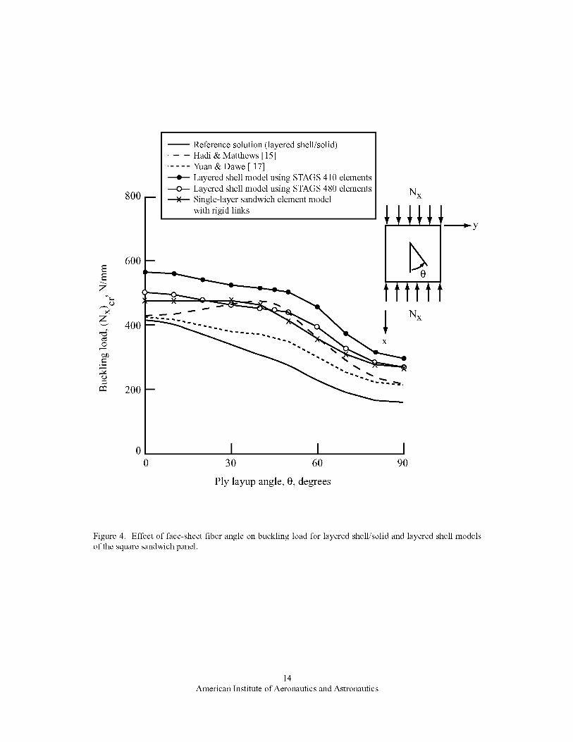
Results of the present analysis approach, of Hadi and
Matthews [15], and of Yuan and Dawe [17], expressed
in terms of the in-plane stress resultant, are shown in
Figure 4 as a function of the fiber orientation in the face
sheet. The present results were generated using a full
panel model with 25 grid points in each planar direction.
These 625 grid points were used to define a finite
element mesh of either 576 4-node quadrilateral shell
elements or 169 9-node quadrilateral shell elements.
Results of the present analysis are presented for layered
shell models with and without shear deformation,
layered shell/solid models, and sandwich element
models. The results shown in Figure 4 indicate that the
layered shell finite element models are stifler and
predict higher buckling loads than the layered shell/solid
finite element model (reference solution). The results
shown in Figure 4 indicate that the layered shell model
without shear deformation (410 element models)
provides a much stifler solution (higher buckling loads)
than the layered shell model with shear deformation
(480 element models) and the buckling load decreases as
the fiber angle increases from zero (results indicated by
filled symbols). Results for the layered shell model with
shear deformation (480 element models) indicate a more
flexible solution (open symbol results) than that
obtained using the 410 element. Results obtained for the
sandwich element model (840 element models) with
rigid links along the boundary edges, denoted by the "x"
symbol, indicate a response similar to that predicted
using a layered shell model with shear deformation. The
rigid links impose classical plate theory kinematics
6
American Institute of Aeronautics and Astronautics
alongthe boundarieswhile internallythe shearflexibilityof thecorematerialis includedin thesimulation.Thebucklingloadisnearlyconstantuptoafiberangleof30degreesandthendecreasesasthefiberanglesincreasesfuxther.
Theresultsshownin Figure4 indicatethatall finiteelementmodelsof thepresentstudyandtheanalysisapproachofYuanandDawe[17]predictamaximumbucklingloadwhentheface-sheetfiberorientationangleequalszerodegreesanda progressivedecreaseinbucklingloadoccursasthefiberorientationangleincreases.HadiandMatthews[15]andadditionalearlieranalyses[13,14]usingaRayleigh-Ritzapproachwithtrigonometricapproximations,however,predictthatthebucklingloadincreaseswithincreasein theface-sheetfiberanglefrom0-degreesupto40-degrees.Thenthebucklingloaddecreasesrapidlytothebucklingload value for the 90-degreecasewhich isapproximatelyhalfthebucklingloadvalueforthe0-degreecase.Thistrendissimilartothetrendobtainedfor a laminatecompositeplatewithanaspectratiogreaterthanone(e.g.,AshtonandWhitney[27]).However,for a squareplatewith thesematerialproperties,thebucklingloaddecreasesasthefiberangleincreases.YuanandDawe[17]reporta decreaseinbucklingloadwithanincreasein fiberangleforthesquaresandwichpanelunderconsiderationandindicatethatRayleigh-Ritzsolutionsbasedontrigonometricseriesoverlyconstrainthepanelasmaterialanisotropyincreases.Doublesine-seriessolutionsforfinitepanelswithsimplysupportedboundaryconditionsandhavingsymmetriclaminatesgiveriseto artificialderivativeboundaryconstraintsthatpreventconvergenceto thecorrectsolution[28,29]. StoneandChandler[29]reportthatbucklingloadswillbeoverestimatedandmaycontributetomisleadingtrendsorconclusions.
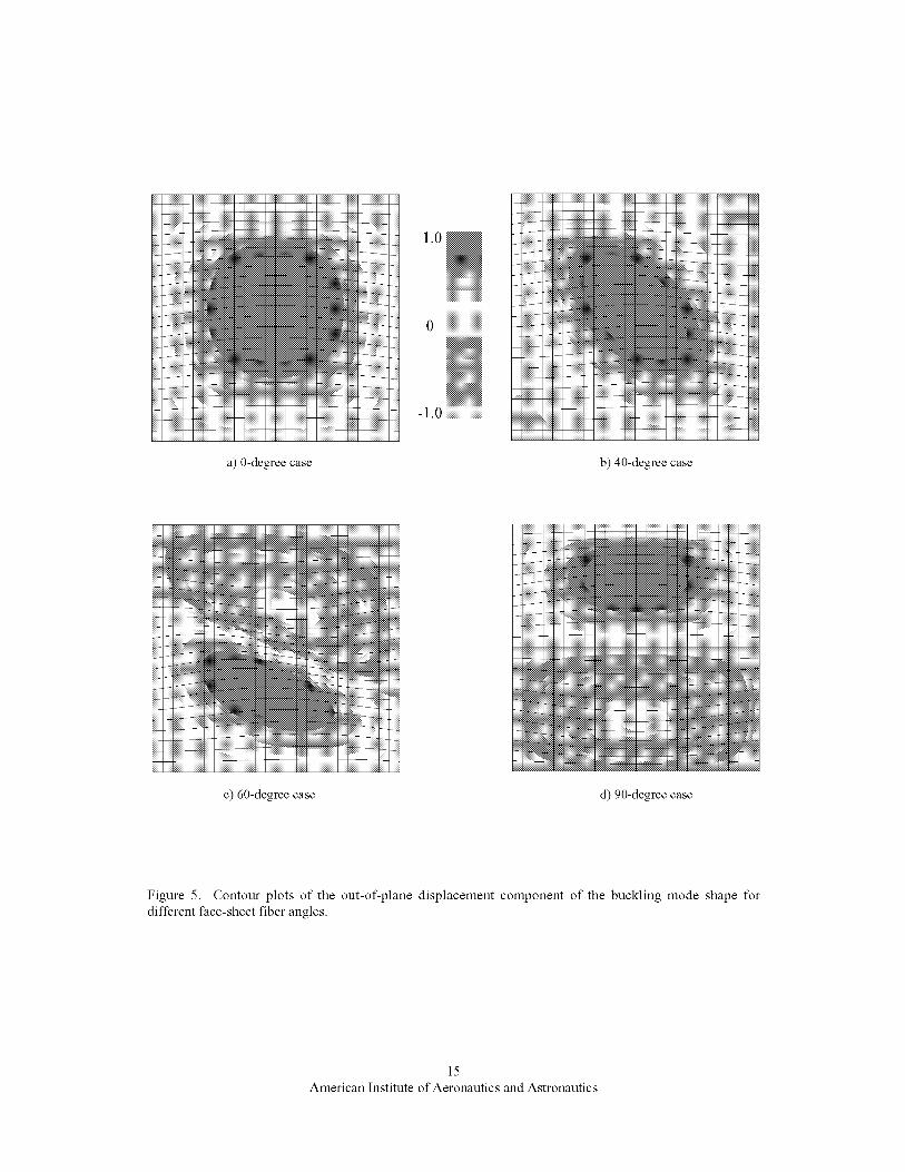
All finiteelementresultsfromthepresentstudyindicatethesamebucklingmodeshape(generalinstability)foranyface-sheetfiberorientation.Initially (0-degreecase)themodeshapeinvolvesonlyonehalf-waveinbothdirections.Astheangleincreases,thebucklingmodeshapebecomesskewedandtendsto followthefiberangle.At approximately60degrees,theskewedmodeshapehastwolongitudinalhalf-wavesandonetransversehalf-wave.Thispatternbecomeslessskewedastheface-sheetfiberangleapproaches90degrees.InFigure5,contourplotsoftheout-of-planedisplacementcomponentofthebucklingmodeshapeareshowntoillustratethiseffectfordifferentface-sheetfiberangles.
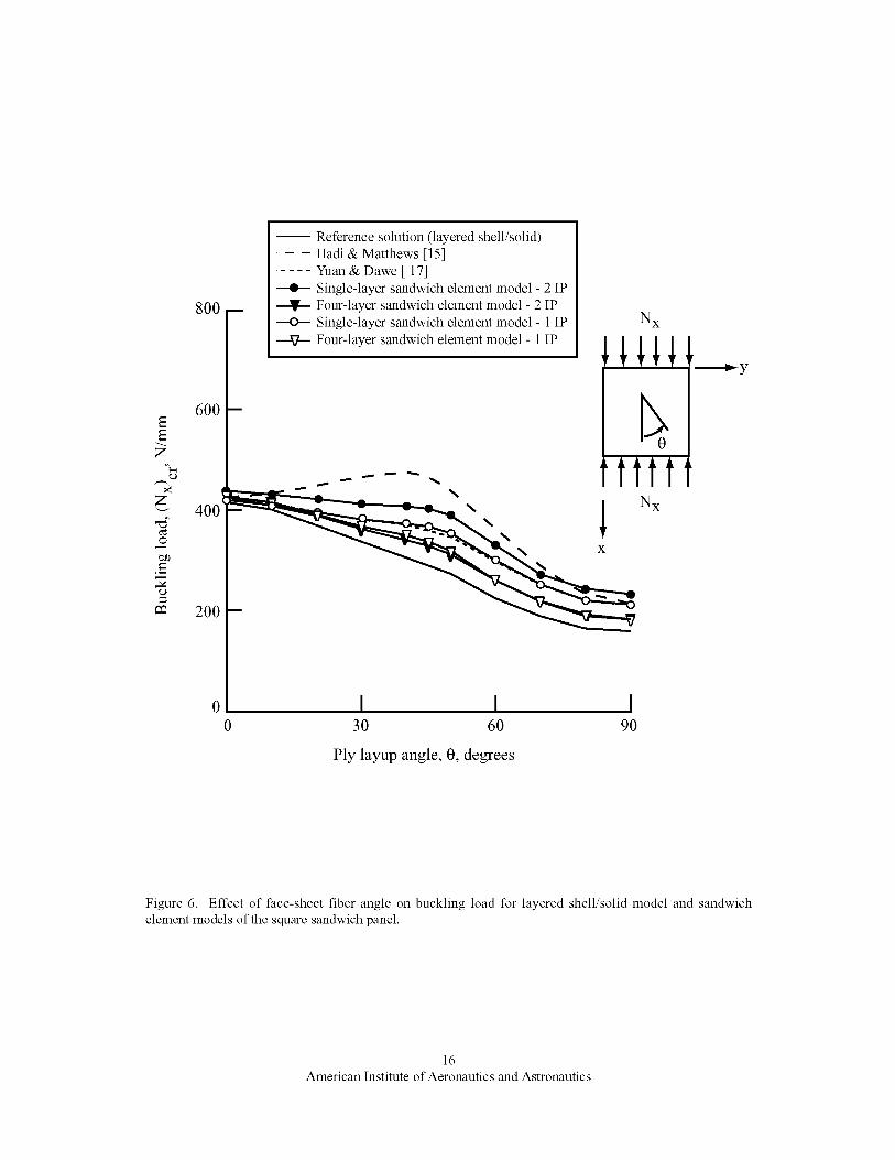
TheeffectoffiberangleonthebucklingresultsobtainedusingthesandwichelementmodelingapproachisshowninFigure6. Resultsareshownforallmodelsusingoneandfoursandwichelementsthroughthecore
thicknesswitheachsandwichelementhavingoneortwointegrationpointsin thethicknessdirection(openandfilledsymbols,respectively).Thefiniteelementmodelsof thefull panelhave25gridpointsin eachplanardirection.Thepresentresultsbracketthesolutionsreportedby YuanandDawe[17]andappearto beconvergingtothereferencesolution.Asthenumberofsandwichelementsthroughthecorethicknessincreases,thesensitivityto thenumberof integrationpointsdecreases.TheseresultsillustratetheeffectivenessoftheSTAGSsandwichelementformulation.
Dueto thenatureof thisproblemandthedifferingresultsobtainedbyvariousresearchers,twoadditionalstudieswereperformedto studytheeffectof thefacesheetmoduliratioandpanelaspectratioonthegeneralinstabilityresponseof asandwichpanel.Resultswereobtainedusingthesandwichelementmodelingapproachwithfourelementsthroughthecorethickness,andtwointegrationpointsthroughthethicknessofeachelement.ResultsforthepresentsquarepanelwithE2/E1 0.058
are shown in Figure 7 along with results for a
rectangular panel with an aspect ratio, a/b, equal to two,
and face-sheet moduli ratio E2/E1 0.058, and for a
square panel with the transverse modulus, E2, doubled
_2/E1 0.116). Results for the square panels with
E2/E1 0.058 and 0.116 are shown by the solid and
dashed lines, respectively, and results for the rectangular
panel are shown by the dotted line. As shown in Figure
7, doubling the ratio of the face-sheet moduli ratio in the
square panel causes an overall increase in the panel
buckling load. Increasing the panel aspect ratio to two,
while holding the face-sheet moduli ratio constant,
results in a variation in the buckling load with face-sheet
fiber angle similar to the variation obtained for a
composite plate with similar material properties and an
aspect ratio greater than one. For this case, the buckling
load increases with an increase in face-sheet fiber angle
up to 25 degrees, and then declines with increase in
face-sheet fiber angle.
Case 2: Rectangular Sandwich Panel
The panel considered has a rectangular planform and is
508-mm long and 254-mm wide (a/b 2). Identical
aluminum face sheets of thickness tf on an aluminum
honeycomb core of thickness hc define the sandwich
panel. Two face-sheet thicknesses are considered in this
study: a thin face sheet with thickness equal to 0.508
mm and a thick face sheet with thickness equal to 2.794
mm. The core thickness is varied from very thin, equal
to the face-sheet thickness, to very thick, approaching
half the panel width. As the core thickness increases,
the buckling response transitions from a general
instability mode to a short wavelength face-sheet-
wrinkling mode. Young's modulus, E, for the
aluminum alloy is equal to 68.95 GPa and Poisson's
7
American Institute of Aeronautics and Astronautics

ratiois equalto 0.3.Thehoneycombcorematerialistreatedashomogeneousisotropicmaterialwithelasticmechanicalpropertiesgivenin Table1.Comparativestudiesareperformedforaspecificpanelgeometryandmaterialdata.AnalyticalresultsarecomputedasthefirstlevelofanalysisfollowingVinson's[20]approachasimplementedin PANDA2[21].FiniteelementanalysesarealsoconductedusingSTAGS.Finiteelementresultsareobtainedusingfullpanelmodelsandlocalstripmodels.All modelingapproachesareusedinthefull panelmodels,andonlythesandwichelementmodelingapproachisusedinlocalstripmodels.
Inthepre-stresscondition,thesandwichpanelisloadedbyauniformendshortening,Uo, applied to the sandwich
face sheets on the ends of the panel at x 0 and x a (see
Figure 2). For the buckling calculations, the boundary
conditions applied to all grid points along each edge are:
u=u 0andw=0 x=0 z=0 along Edge 1 (x 0);
w=Oy=0 along Edges 2 and 4 (y b and y 0,
respectively); and u =-u 0 andw=0 x =0_ =0 along
Edge 3 (x a). In addition, a point at the center of the
panel has v 0 to remove rigid body motion.
The finite element mesh for the full panel used in the
present study has 81 grid points along the panel length
and 21 grid points across the panel width. This spatial
discretization (1,701 grid points) is held constant during
the parametric studies and is adequate to represent
buckling modes with up to sixteen half-waves along the
panel length and four half-waves across the panel width.
The mesh of 4-node elements (3,200 elements) has four
times the number of elements as the mesh of 9-node
elements (800 elements). A layered shell modeling
approach is attractive when general instability is
anticipated because of the simplicity, ease of modeling
and low computational cost of this modeling approach
as compared to the other modeling approaches.
In the present study, the local strip model with a width
equal to 2.54 mm and 25 sandwich elements through the
core thickness is used to investigate face-sheet
wrinkling. One integration point is used through the
thickness of each sandwich element. The local strip
model has a uniform stress state in the face sheets and
buckling boundary conditions associated with a
symmetric response. For small values of hc/a, the
PANDA2 wrinkling loads correlate well with those from
the STAGS local strip model. For larger values of hJa,
however, the PANDA2 wrinkling loads are much lower
than those predicted by the STAGS model. Apparently
the through-the-thickness assumptions made in
PANDA2 are quite conservative. Based on the
PANDA2 predictions, the core thickness that
corresponds to a transition from a general-instability
mode to a face-sheet-wrinkling mode is approximately
hJa 0.020 for the thin face-sheet case and hJa 0.060
for the thick face-sheet case.
Linear buckling analysis results obtained from the full
panel layered shell models indicate overall panel
buckling regardless of the core thickness and the face-
sheet thickness. In all cases, the buckling mode
corresponds to an overall panel mode with two half-
waves along the length and one half-wave across the
panel width. In addition, the buckling results obtained
using the 410 element are higher than the buckling
results obtained using the 480 shear-flexible element, as
expected. Good correlation between the layered shell
model results and the analytical results from PANDA2
is obtained for sandwich structuJces with a very thin core.
However, the finite element results based on the layered
shell modeling approach quickly tend to deviate from
the analytical results as the core thickness increases for a
given panel length (increasing values of hJa) due to
limitations in the layered shell models for modeling the
core shear behavior and through-the-thickness
flexibility.
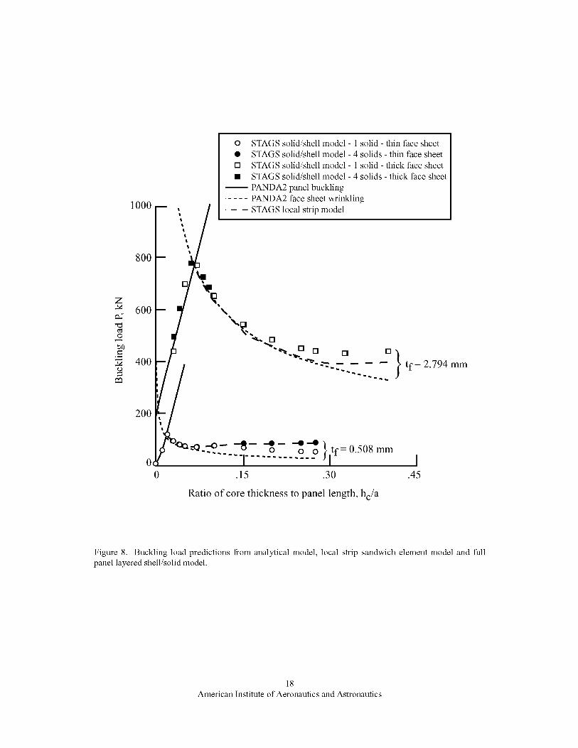
Results obtained using the analytical model in
PANDA2, the STAGS local strip wrinkling model, and
the STAGS full panel layered shell/solid model are
compared in Figure 8. PANDA2 wrinkling predictions
are shown by the dotted line, the STAGS wrinkling
model predictions are shown by the dashed line, and the
STAGS full-panel layered shell/solid model predictions
are shown by the symbols. In the layered shell/solid
models, the core material is discretized using either one
or four 27-node solid brick elements through the core
thickness (open symbols and filled symbols,
respectively, in Figure 8). PANDA2 overall panel
buckling results are also shown as a solid curve in
Figure 8. The results shown in Figure 8 indicate that the
transition from an overall panel buckling mode to a
wrinkling buckling mode occurs at a small value of the
core thickness to panel length ratio (hJa). In addition,
these results show excellent agreement between the
PANDA2 wrinkling results and the wrinkling results
obtained with the local strip model for moderately thick
sandwich panels (for ratio of core thickness to face-sheet
thickness less than 50). For panels with a ratio of core
thickness to face-sheet thickness greater than 50,
PANDA2 wrinkling results appear to be conservative, as
a result of an assumed linear displacement response
through the thickness of the core. The local strip model
allows a piecewise linear distribution using 25 sandwich
elements through the core thickness. In addition, the
buckling results summarized in Figure 8 show that for
the thin face-sheet case results obtained using the
layered shell/solid models correlate well with the
analytical results when just a single solid element
8
American Institute of Aeronautics and Astronautics

throughthecorethicknessisused.Goodcorrelationisalsoshownbetweentheresultsobtainedusingthelocalstripmodelandresultsobtainedusingthelayeredshell/solidmodelwhenfoursolidelementsthroughthecorethicknessareused.Forthethickface-sheetcasewithtj-2.974 mm and hJa 0.4, the layered shell/solid
models predict a buckling load that is approximately 8%
higher than the buckling load predicted by the local strip
model. The results for tj-2.974 mm and hJa 0.4
indicate that the buckling load predicted by the layered
shell/solid models is converging to 430.03 kN. The
convergent behavior of the layered shell/solid modeling
approach is evident even for short wavelength face-
sheet-wrinkling behavior with only a 2% change
between the buckling load predictions obtained with one
element and four elements through the core thickness.
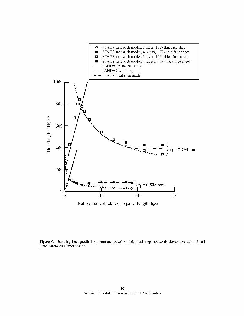
Similar results for sandwich element models are
summarized in Figure 9. The sandwich element models
have the same discretization as the finite element models
with 4-node quadrilaterals. In these models, the core
material is discretized using either one or four sandwich
elements through the core thickness with "phantom"
face sheets for the intermediate layers (open symbols
and filled symbols, respectively, in Figure 9). Results in
Figure 9 show that for the thin face-sheet case, the
sandwich element models with one integration point
correlate well with the analytical results and with results
obtained using the local strip model. Use of two
integration points through the thickness of each
sandwich element results in a stifler response and higher
buckling loads. Similar trends are observed for the thick
face-sheet cases, However, as the core thickness
increases, this convergent behavior is less evident. For
example, results obtained using one integration point per
layer for the thick face-sheet case and hc/a 0.4, indicate
an increase in buckling load as the number of layers
increases from one to four. Further analyses conducted
using six and eight sandwich elements through the
thickness predict buckling loads of 432.99 kN and
435.31 kN, respectively, thereby indicating a slow
convergence. Use of two integration points per layer
results in a very stiff solution for a single layer model,
and the buckling load is nearly four times the value
predicted with a four layer model. Additional analyses
were performed using six and eight sandwich elements
with predicted buckling loads of 479.28 kN and 461.93
kN, respectively. Again the results appear to be
converging but extremely slowly for the case of two
integration points per layer. These results indicate that
the sandwich element modeling approach, while quite
powerful for modeling large-scale structures exhibiting a
general instability, is not effective in a large-scale sense
for predicting face-sheet-wrinkling buckling modes
unless local strip models are used.
Finally, a limited review of the computational cost
associated with the sandwich element and layered
shell/solid element modeling approaches was performed
for the thin face-sheet case with hJa 0.1. The
sandwich element approach exploits the 4-node C 1 shell
element formulation while the layered shell/solid
element approach is based on the ANS formulation for a9-node C o shell element and a 27-node solid element.
For a fixed finite element discretization (same number
of grid points) in the plane of the sandwich panel, the
critical buckling load for the sandwich element
modeling approach changes from 52.1 kN to 67.6 kN to
76.8 kN as the number of through-the-thickness layers
increases from one to two to four, respectively.
Similarly, the layered shell/solid modeling approach
gives critical buckling loads that change from 77.7 kN to
75.2 kN to 73.7 kN as the number of through-the-
thickness layers increases from one to two to four,
respectively. Clearly for this wrinkling mode response,
the layered shell/solid modeling approach converges
more quickly than the sandwich element modeling
approach. The advantage of using the sandwich element
modeling approach from a computational cost
perspective decreases as the number of sandwich
element layers increases. The computational effortassociated with a sandwich element model is defined in
terms of the number of through-the-thickness layers
which in turn increases the size of the global stiffness
matrix. The number of equations in the global stiffness
matrix for a model with a single layer of sandwich
elements is approximately 60% of that for a layered
shell/solid model with a single solid element in the core.
As the number of layers of sandwich elements increases,
the number of equations increases proportionally in
addition to the computational effort expended at the
element level. Buckling values obtained using either
approach with four layers through the thickness are
nearly equal. However, the solutions obtained with a
single layer of sandwich elements require only 60% of
the computational effort required to obtain a solution
with a single solid element in the core. Approximately
the same level of solution accuracy is achieved by using
a single solid element in the core of a layered shell/solid
model as is obtained by using four layers of the
sandwich elements. In this case, the computational cost
for the sandwich element modeling approach is over
four times the computational cost of the layered
shell/solid model to achieve equal levels of solution
accuracy. Extrapolation of this cost differential to large-
scale structural panels is not expected to apply because
of solid element aspect ratio limits. However, use of the
sandwich element modeling approach for large-scale
sandwich structures provides an effective means to
determine its general-instability buckling response.
9
American Institute of Aeronautics and Astronautics
ConclusionsA comparativestudyofdifferentmodelingapproachesfor predictingsandwichpanelbucklingresponsehasbeenpresented.Thestudyconsideredsandwichpanelswithanisotropicfacesheetsanda verythickcore.Resultsfromconventionalanalyticalsolutionsforsandwichpaneloverallbucklingand face-sheet-wrinklingtypemodeswerecomparedwithsolutionsobtainedusingdifferentfinite elementmodelingapproaches.ThenumericalanalyseswereconductedusingtheSTAGSnonlinearfiniteelementcode,andtheanalyticalresultswerecomputedusingPANDA2.Finiteelementsolutionswereobtainedusinglayeredshellelementmodels,withandwithouttransverseshearflexibility,layeredshell/solidelementmodels,thatuseshellelementsforthefacesheetsandsolidelementsforthe core,and sandwichmodelsusinga recentlydevelopedspecialtysandwichelement.Convergencecharacteristicsof theshell/solidandsandwichelementmodelingapproacheswith respectto in-planeandthrough-the-thicknessdiscretization,weredemonstrated.
Resultsofthestudyindicatethatthespecialtysandwichelementformulationimplementedin STAGSprovidesan accurateandeffectivemodelingapproachforpredictingbothoverallandlocalizedbehavior.Thismodelingapproachprovidestheflexibilityformodelinganentirepanelorformodelinglocaldetailthroughthecorethickness.Resultsof thestudyindicatethattransitionfroma generalinstabilitymodeto a shortwavelengthface-sheet-wrinklingmodeoccursasthecorethicknessisincreased.Modelingfidelitytocapturebothpossiblemodesmustbe providednearthetransitionregion.Furthermore,resultsindicatethatanisotropyofthefacesheets,alongwiththeratioofprincipleelasticmoduli,significantlyaffectthebucklingresponse,andtheseeffectsmaynotbeaccuratelyrepresentedbyanalyticalsolutions.
AcknowledgementTheworkofthesecond,thirdandfourthauthorswassupportedbytheNASALangleyResearchCenterundercontractsNAS1-00135,GS-35F-0038J(Task1730),andNAS1-99069,respectively.
References
1. Allen, Howard G., "Sandwich Construction Today
and Tomorrow," in Sandwich Construction 1, Karl-
Axel Olsson and Ronnal P. Reichard (editors),
Proceedings of the First International Conference on
Sandwich Constructions, Stockholm, Sweden, June
19-21, 1989, pp. 3-22.
2. Plantema, F. J., Sandwich Construction, John
Wiley, New York, 1966.
3. Anon., Structural Sandwich Composites, Mil-
HDBK-23A, Department of Defense, Washington,
D.C., 1968.
4. Benson, A. S. and Mayers, J. "General Instability
and Face Wrinkling of Sandwich Plates Unified
Theory and Applications," AIAA Journal, Vol. 5,
No. 4, April 1967, pp. 729-739.
5. Ha, K. H., "Finite Element Analysis of Sandwich
Construction: A Critical Review," in Sandwich
Construction 1, Karl-Axel Olsson and Ronnal P.
Reichard (editors), Proceedings of the First
International Conference on Sandwich
Constructions, Stockholm, Sweden, June 19-21,
1989, pp. 69-85.
6. Ha, K. H., "Finite Element Analysis of Sandwich
Plates: An Overview," Computers and Structures,
Vol. 37, No. 4, 1990, pp. 397-403.
7. Frostig, Y., "Buckling of Sandwich Panels with a
Flexible Core High-Order Theory," International
Journal of Solid and Structures, Vol. 35, Nos. 3-4,
1998, pp. 183-204.
8. Tessler, A., Annett, M. S., and Gendron, G., "A
{1,2}-Order Plate Theory Accounting for Three-Dimensional Thermoelastic Deformations in Thick
Composites and Sandwich Laminates," Composite
Structures, Vol. 52, 2001, pp. 67-84.
9. Vonach, W. K. and Rammerstorfer, F. G., "A
General Approach to the Wrinkling Instability of
Sandwich Plates," Structural Engineering and
Mechanics, Vol. 12, No. 4, 2001, pp. 363-376.
10. Bert, C. W., "Shear Deformation and Sandwich
Configuration," in Buckling and Postbuckling of
Composite Plates, G. J. Turvey and I. H. Marshall
(editors), Chapman and Hall, 1995, pp. 157-189.
11. Noor, A. K., Burton, W. S., and Bert, C. W.,
"Computational Models for Sandwich Panels and
Shells," Applied Mechanics Reviews, Vol. 49, No.
3, March 1996, pp. 155-199.
12. Librescu, L. and Hause, T., "Recent Developments
in the Modeling and Behavior of Advanced
Sandwich Constructions: A Survey," Composite
Structures, Vol. 48, Nos. 1-3, January-March 2000,
pp. 1-17.
10
American Institute of Aeronautics and Astronautics

13.Rao,K. M., "BucklingAnalysisof AnisotropicSandwichPlatesFacedwith Fiber-ReinforcedPlastics,"AIAA Journal, Vol. 23, No. 8, August
1985, pp. 1247-1253.
14. Kim, C. G. and Hong, C. S., "Buckling of
Unbalanced Anisotropic Sandwich Plates with
Finite Bonding Stiffness," AIAA Journal, Vol. 26,
No. 8, August 1988, pp. 982-988.
15. Hadi, B. K. and Matthews, F. L., "Predicting the
Buckling Load of Anlsotropic Sandwich Panels: An
Approach Including Shear Deformation of the
Faces," Composite Structures, Vol. 42, No. 3, July
1998, pp. 245-255.
16. Dawe, D. J. and Yuan, W. X., "Overall and Local
Buckling of Sandwich Plates with Laminated
Faceplates, Part I: Analysis," _bmputer Methods' in
Applied Mechanics and Engineering, Vol. 190,
2001, pp. 5197-5213.
17. Yuan, W. X. and Dawe, D. J., "Overall and Local
Buckling of Sandwich Plates with Laminated
Faceplates, Part II: Applications," Computer
Methods' in Applied Mechanics and Engineering,
Vol. 190, 2001, pp. 5215-5231.
18. Rankin, C. C., Brogan, F. A., Loden, W., and
Cabiness, H., Structural Analysis of General Shells'
- STAGS User Manual, Version 4.0, Lockheed
Martin Advanced Technology Center, Palo Alto,
CA, June 2000.
19. Brush, D. O. and Almroth, B. O., Buckling of Bars,
Plates' and Shells', McGraw-Hill, New York, 1975.
20. Vinson, J. R., "Optimum Design of Composite
Honeycomb Sandwich Panels Subjected to Uniaxial
Compression," AIAA Journal, Vol. 24, No. 10,
October 1986, pp. 1690-1696.
21. Bushnell, David "Optimum Design via PANDA2 of
Composite Sandwich Panels with Honeycomb or
Foam Cores," AIAA Paper No. 97-1142, April1997.
22. Allen, H. G. and Feng, Z., "Classification of
Structural Sandwich Panel Behavior," in Mechanics
of Sandwich Structures, A. Vautrin (editor),
Proceedings of the EUROMECH 360 Colloquium
held in Saint-Etienne, France, 13-15 May 1997,
Kluwer Academic Publishers, Dordrecht, 1998, pp.
1-12.
23. Riks, E. and Rankin, C. C., "Sandwich Modeling
with an Application to the Residual Strength
Analysis of a Damaged Composite Compression
Panel," AIAA Paper 2001-1323, April 2001.
24. Rankin, C. C. and Brogan, F. A., The
Computational Structural Mechanics TestbedStructural Element Processor ES5: STAGS Shell
Element, NASA CR-4358, 1991.
25. Stanley, G. M., The Computational Structural
Mechanics Testbed Structural Element Processor
ESI: Basic SRI and ANS Shell Elements', NASA
CR-4357, 1990.
26. Park, K. C. and Stanley, G. M., "A Curved C O Shell
Element Based on Assumed Natural-Coordinate
Strains," ASME Journal of Applied Mechanics, Vol.
108, 1986, pp. 278-290.
27. Ashton, J. E. and Whitney, J. M., Theory of
Laminated Plates', Technomic Publishing Co., 1970.
28. Dawe, D. J. and Peshkam, V., "Buckling and
Vibration of Finite-Length Composite Prismatic
Plate Structures with Diaphragm Ends, Part I: Finite
Strip Formulation," Computer Methods' in Applied
Mechanics and Engineering, Vol. 77, Nos. 1-2,
December 1989, pp. 1-30.
29. Stone, M. A. and Chandler, H. D., "Errors in
Double Sine Series Solutions for Simply Supported
Symmetrically Laminated Plates," International
Journal of Mechanical Sciences, Vol. 38, No. 5,
1996, pp. 517-526.
Table 1. Elastic mechanical propertiesfor core materials
Material Properties Case 1 Case 2
Ecx Ecy, MPa 200 0.6895
Ecz, MPa 200 68.95
Gcxy, MPa 146 0.265
G .... MPa 146 82.74
Gcyz, MPa 90.4 49.64
Vcxy 0.3 0.3
Voxz Voyz 0.3 0.01
11
American Institute of Aeronautics and Astronautics
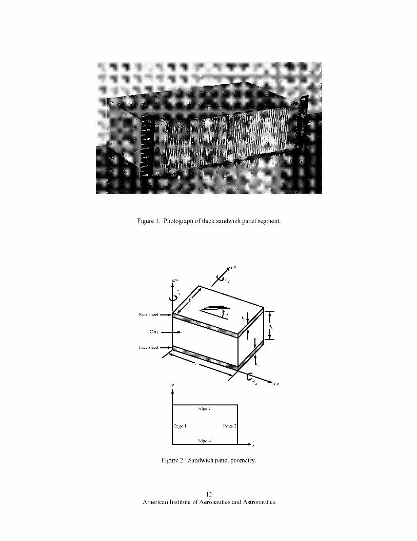
Figure1. Photographofthicksandwichpanelsegment.
Face sheet _ tf
Core 2
Face sheet
Edge 2 ]
_dge 1 Edge 3
Edge 4x
Figure 2. Sandwich panel geometry.
12
American Institute of Aeronautics and Astronautics
1.6
Z1.3
Z
©
= 1.0
©
Z
0.7
Layered shell/solid - 1, 2, 4 layers
One sandwich layer - 2 IP
Two sandwich layers - 2 IP
Four sandwich layers - 2 IP
Eight sandwich layers - 2 IP
.- _- - One sandwich layer - 1 IP
.- ,_ - Two sandwich layers - 1 IP
.- _- - Four sandwich layers - 1 IP
.- 43 - Eight sandwich layers - 1 IP
N x
ttttl
)[ R X
I I I10 20 30
Number of grid points per edge
Figure 3. Effect of mesh refinement for sandwich element models for the square sandwich panel with a 30-
degree fiber angle.
13
American Institute of Aeronautics and Astronautics
800 --
-- Reference solution (layered shell/solid)
- - Hadi & Matthews [15]
..... Yuan & Dawe [ 17]
Layered shell model using STAGS 410 elements
----O-- Layered shell model using STAGS 480 elements
-----)b- Single-layer sandwich element model
with rigid links
_-y
0 I I I0 30 60 90
Ply layup angle, 0, degrees
Figure 4. Effect of face-sheet fiber angle on buckling load for layered shell/solid and layered shell models
of the square sandwich panel.
14
American Institute of Aeronautics and Astronautics
a)0-degreecase
>>>>>>>>_
iiiiiiiiiiiiiiiiiiiiiiiiiiiiiiiiilililililililililililililililll0
N®iiiiiiiiiiiiiiiiiiiiiiiiiiiiiiiiii
-1.0 iiiiiiiiiiiiiiiiiiiiiiiiiiiiiiiiiiiiiiii iiiiiiiii
b) 40-degree case
c) 60-degree case d) 90-degree case
Figure 5. Contour plots of the out-of-plane displacement component of the buckling mode shape for
different face-sheet fiber angles.
15
American Institute of Aeronautics and Astronautics
Z
Z
©
m
800 --
600 --
200 --
0
0
-- Reference solution (layered shell/solid)
- - Hadi & Matthews [15]
..... Yuan & Dawe [ 17]
Single-layer sandwich element model - 2 IP
Four-layer sandwich element model - 2 IP
----O-- Single-layer sandwich element model - 1 IP
----V-- Four-layer sandwich element model - 1 IP
I I I30 60 90
Ply layup angle, 0, degrees
N x
Figure 6. Effect of face-sheet fiber angle on buckling load for layered shell/solid model and sandwich
element models of the square sandwich panel.
16
American Institute of Aeronautics and Astronautics

8OO
600
Z
¢..)
%
E 400
o
200
E2/E 1 = 0.058, a/b = 1
E2/E 1 = 0.116, a/b = 1
E2/E 1 = 0.058, a/b = 2
"'_ X
sss ¢SS-- _ _ _
0
I I I30 60 90
Ply layup angle, 0, degrees
Figure 7. Effect of face-sheet fiber angle, aspect ratio, and face-sheet elastic modulus ratio (E2/E1) on
buckling load for a sandwich element model of the square sandwich panel.
17
American Institute of Aeronautics and Astronautics
z
©
m
1000
800
600
400
200
/
O STAGS solid/shell model - 1 solid - thin face sheet
• STAGS solid/shell model - 4 solids - thin face sheet[] STAGS solid/shell model - 1 solid - thick face sheet
• STAGS solid/shell model - 4 solids - thick face sheet
-- PANDA2 panel buckling
..... PANDA2 face sheet wrinkling
- - STAGS local strip model
\
[]
tf 2.794 mm
_.C___ _.0_ -._-- -4-- -...04-_ ...... '-' o o o } 0.508 mm0 "7 ............. [tf= [
0 .15 .30 .45
Ratio of core thickness to panel length, hc/a
Figure 8. Buckling load predictions from analytical model, local strip sandwich element model and fullpanel layered shell/solid model.
18American Institute of Aeronautics and Astronautics
1000
800
z600
¢_©
= 400
O STAGS sandwich model, 1 layer, 1 IP- thin face sheet• STAGS sandwich model, 4 layers, 1 IP - thin face sheet[] STAGS sandwich model, 1 layer, 1 IP- thick face sheet• STAGS sandwich model, 4 layers, 1 IP- thick face sheet
-- PANDA2 panel buckling..... PANDA2 wrinkling
- - STAGS local strip model
%
tf = 2.794 mm
200
..4-- ..o-- -o-- --O-.o)[tfj,O, "-0 .... t_ - - - "0- - - - ..,0, _D [
0 .15 .30 .45
= 0.508 mm
Ratio of core thickness to panel length, hc/a
Figure 9. Buckling load predictions from analytical model, local strip sandwich element model and fullpanel sandwich element model.
19American Institute of Aeronautics and Astronautics