Embed Size (px)
Citation preview
A TUKABLE TV/0 FREQUENCY OUTPUT, GIANT PULSE RUBY LASER.
"by
MARTIN a. RICHARDSON B.Sc., A.R.C.S.
Submitted for the Ph.D. Degree, University of London,
Department of Physics, June, 1967,Royal Holloway College,
ProQuest Number: 10096734
All rights reserved
INFORMATION TO ALL USERS The quality of this reproduction is dependent upon the quality of the copy submitted.
In the unlikely event that the author did not send a complete manuscript and there are missing pages, these will be noted. Also, if material had to be removed,
a note will indicate the deletion.
uest.
ProQuest 10096734
Published by ProQuest LLC(2016). Copyright of the Dissertation is held by the Author.
All rights reserved.This work is protected against unauthorized copying under Title 17, United States Code.
Microform Edition © ProQuest LLC.
ProQuest LLC 789 East Eisenhower Parkway
P.O. Box 1346 Ann Arbor, Ml 48106-1346

ABSTRACT
A Tunable Two Frequency Output, Giant Pulse Ruby Laser.
A brief survey is given of the progress made in the study and development of Q-switohed lasers in recent years, and a review of the theory relevant to the work described, is outihed.
A gain-switched giant pulse ruby laser system, employing two ruby rods of differing lengthsin a single resonant cavity coupled with a rotating prism,has been developed. A systematic study of the output characteristics of this system under various conditions has been carried out. High resolution spectroscopy, including nanosecond time-resolution, of the emission of this laser, and also of a Pockels Cell switched laser, has rendered possible the direct observation of the axial and off-axial mode structure,and has shown the existence of an intensity pendent frequency shift towards higher frequency in the giant pulses.
When the two ruby rods in the gain-switched device
— 2—

are differentially cooled, simultaneous two frequency output pulses with powers in the tens of megawatt region are obtained, the wavelength separation of the two frequencies being tunable from 1 to 5.5%. The suitability of this device for certain experiments in non-linear optics, such as the generation of the sum and difference frequencies in crystals, and nonlinear resonance mixing in plasmas, is considered.The two frequency output of the laser system has been mixed in ADP, to generate the sum frequency, and the conversion efficiency of the latter process compared with that of second harmonic generation.
•“ 3—

CONTENTS
PagoABSTRACT :................... 2CONTENTS 4CHAPTER I; SURVEY OE RELEVilNT AREAS OE LASER PHYSICS1.0; The Advent of The Laser ............... 91.1: Early Advances in Puby Laser Physics..........121.2; The Technique of Q-Switching. ........141.3: Giant Pulse Generation by Gain Switching 171.4: Effect of Variation of Temperature on Laser
Action in Ruby................................191.5: Spectroscopic Techniques Employed in Laser
Research. ........... 211.6: Non-linear Optical Phenomena. ................231.7: Non-linear Optical Effects in Plasmas ....251.8; Simultaneous Two Frequency Laser Output .27
CHAPTER 2: SOME THEORETICAL ASPECTS OF GI iNT PULSE LASERS.
2.0: Giant Pulse Dynamics ......... ..302.1: Simplified Theory of Q-Modulation.............312.2; Theory Associated with Gain Switching.........362.3; Modes of a Resonant Cavity....................38
- 4-

PageCHAPTER 3 : THEORETICAL OUTLINES OE SOME NON-LIHEAR
OPTICAL PHENOMENA.3.0: Non-linear Susceptibility................... 423.1: The Lowest Order Non-linear Polarization.....433.2; Phase Matching........... 443.3: Conclusions from Kleinman’s Theory...........453.4: Optical Mixing in a Plasma....... .....49
CHAPTER 4 ; THE DESIGN AND TECHNOLOGY OE THE LASER SYSTEM. •
4.0: Adoption of a Single Resonator Cavity... 524.1: Choice of Main Components. .............534.2: Design of the Laser System...... .......604.3: Electronics Associated with Operation of
Laser System.............................644.4: Resonator End Mirrors ...... 674.5: The Cooling System...........................684.6; Alignment of the Laser System............. ..714.7: Monitoring Techniques....................... 73
- 5-
PageCHAPTER 5: SPECTROSCOPIC IHSTRTO-ÎENTS USED IN THE
EXPERIMENT.5.0: Eabry-Pcrot Techniques............... ...755.1: Practical Considerations Associated with the
Plane Pabry-Perot Interferometer...............765.2: Inadequacy of the Plane Pabry-Perot at High
Resolving Powers. ...... .805.5: The Spherical Pabry-Perot Interferometer.......825.4: The Use of the Spherical Interferometer........87
CHAPTER 6; HIGH RESOLUTION SPECTROSCOPY OE GIANT PULSE LASER EMISSION.
6.0; Narrow Linewidth Giant Pulse Lasers...... .926.1: Longitudinal Mode Selecting Techniques.........936.2: Multielement Resonant Reflectors...............976.3: High Resolution Spectroscopy of the Gain
Switched Laser. ...... .1006.4: High Resolution Spectroscopy of a Pockels Cell
Switched Laser. .1046.5: Time Resolved Spectroscopic Analysis of Mode
Structure............. 1076.6: Some Conclusions from this Spectroscopic
Analysis....... 114

PageCHi'VPTER 7 : TWO FREQUENCY OUTPUT OE THE LASER.7.0; Scope of the Spectroscopic Study,,,....,,....1187.1: Some Characteristics of the Laser System 1197.2: Tunable Two Frequency Output of the Laser....121 7.3: Time Resolved Spectroscopy of the Two Frequency
Output........... 1297.4: Two Frequency Output of the Laser System
Q-Switched with a Saturable Absorber.......*.135
CHAPTER 8 : OPTICAL Smi GENERATION OF THE TWO FREQUENCY OUTPUT OF THE LASER.
8.0: Advantages of the Present System.............1408.1: Previous Experiments.........................1418.2: The Experimental Arrangement.................1438.3: Second Harmonc Generation: Phase Matching..147 8.4: Sum Frequency Generation.....................1508.5; Comparison of Intensities. ..................153
~ 7~

PageCHAPTER 9 ; FURTHER APPLICATIONS OE^THE LASER
SYSTEM9.0: Possible Fields in which the Laser may have
Applications ......... .1559.1: The Generation of Millimetre Wa,vcs as a
Difference Frequency. ..... .1569.2: Use of the Laser System for the Generation
and Detection of Resonant Plasma Oscillations.157CONCLUSIONS: ........ 161ACIŒ0VÆEDGE1.HCHTS ;..................................164REFERENCES :................. .....................165
- 8 -

CHAPTER I; SURVEY OE RELEVANT AREAS OF LASER PHYSICS.
1.0 The Advent of the Laser.Although the notion of stimulated emission was shown
hy Einstein (83) in 1917 to be a necessary process in the interaction of radiation and matter, it v/as not until several decades later, that definite proposals were advanced, independently by several investigators, to apply the phenomena of stimulated emission to the amplification of radiation (07, 22, 239, 230). Subsequently, a molecular amplifier and oscillator operating in the microwave region, utilizing an inversion transition of ajnmonia, was developed by Gordon, Zeiger and Townes (101, 102, 205^; a similar device was proposed by Basov and Prokhorov (23).
In 1958, Schawlow and Townes (202) and others (190,77) considered the extension of the maser technique from the microwave region to the infrared and visible wavebands.This involved several problems, in that, in the microwave region, photon energies are small, the cavity dimensions are comparable with the wavelength of the emitted radiation, and spontaneous emission is negligible. Whereas, in the optical region the reverse is true, the photon energy is
— 9—

comparatively large, the cavity dimensions are necessarily several orders of magnitude greater than the wavelength of the emitted radiation, and thus, it is necessary either to minimise the number of modes into which spontaneous emission can occur, or utilize mode selection techniques to restrict amplification only to certain modes. The latter technique was adopted by Maiman (152,153,154,155,156), in constructing the first pulsed solid state maser in the optical region, oscillating at 6943%. This was achieved by producing population inversion in a short cylindrical length of pink ruby crystal (0.050 Cr^^ concentration) with partially reflecting silver coatings on the polished flat and parallel ends, by optically pumping with the intense radiation from a helical flashtube.
This success aroused the interests of many workers and as a consequence laser research gathered momentum at a prodigious rate. After Maiman*s success, Javan, Herriott and Bennett developed the first CW laser, by exciting a mixture of helium and neon in a discharge located between the mirrors of a Pabry-Perot resonator (118). The output power was many orders of magnitude less than that of the solid state device, but since a gaseous medium is inherently more optically homogeneous than a solid crystal, the spectral purity, spacial coherence and directionality were far
— 10—

superior. , Butayova and Pabrikant(57) in 1957, looked for negative absorption in a number of materials, such as Cs, but their results were inconclusive. Basov et al (24) gave a mathematical treatment of the conditions under which exchange of excitation in a mixture of different gases would produce negative absorption. Almost simultaneous with the development of the gas laser the successful operation of new solid state lasers such as, Sm * and U^’*' in CaP2(218), red ruby (240, 203) and Nd^^ embedded in crystals (122) and glass (211) were reported.
Speculation into the possibility of using semiconductors as laser materials was finally realized in 1962, when several workers reported laser oscillation in GaAs p-n diodes (105,177,191),
This short introductory survey of the highlights in the advent of the laser is of necessity, brief and incomplete. À more comprehensive history of the evolution of the maser and laser has recently been compiled by lengyel (137), Since the work concerned with in this dissertation is on the properties and applications of pulsed solid state lasers, future discussion will be restricted to this type of laser action, and in particular to that of oscillation in ruby.
- 11-

1.1: Early Advances In Ruby Laser Physics.After the success of Maiman in developing the first
ruby laser, research into the properties and applications of this device proceeded at an unprecedented pace. The unique nature of laser light provoked numerous studies of its spectral, coherence and directionality characteristics.
The spectral features of the irregular pulsations or ’’spikes" of the ruby relaxation oscillation laser were soon under close scrutiny. The early adoption of Pabry-Perot spectroscopic techniques resulted in the identification of a series of axial, modes (11, 62), the beat frequencies betv/een v/hich being observed by mixing different modes in a photodetector (73,14-8), Axial modes in a giant pulse laser were first spectrally resolved by Bradley et al (43). Past time resolved interferomctric techniques led to the observation of a frequency shift, attributed to the change in length and refractive index of the ruby crystal with temperature (106,114), and also a variation of the oscillatory mode pattern from one spike to the next. As a consequence of this, the individual spikes were found not to be coherent with one another (29).
The differences in the directionality qualities of laser light and thermal light were studied by Collins et al (64,179). Whilst the fluorescence radiation from the laser
- 12-

before threshold was essentially nondirectional, the laser light was emitted within an angle of a fraction of a degree. However, this was considerably larger than that expected from diffraction theory. This discrepancy was explained when examination of the radiation pattern on the face of the ruby showed a non-uniform distribution of isolated luminous spots which individually satisfied the diffraction theory (84). Further work showed that the divergence of the beam resulted from a non-uniform phase distribution over the end surfaces of the ruby, although there was partial coherence across the latter (94).
The polarization of the output of the laser was shown to depend on the orientation of the crystal optic axis to the cylinder axis| for 0 deg. crystals the output is unpolarized, while for 90 deg. crystals the output is 1000 linearly polarized with plane of polarization perpendicular to the plane ofthe crystal axis (180).
The above is an extremely condensed résumé of the progress m^de in probing the properties of ruby laser light, and in no way does justice to the effort which was made.Some measure of the actual endeavour expended in the laser field may be drawn from the fact that since I960, there have been six major international conferences devoted to quantum electronics, the published proceedings of which provide a
— 13—

more complete picture (1,2,3,4,8). Several international summer schools have also been held (3,6).
Apart from numerous review papers which have been published on laser science as a whole, and on specific fields of laser research, several monograms on the subject have been written (136,107,231). Recently, more comprehensive works have been published (54, 138,7,195,210).
1.2: The Technique of Q-Switching.Stemming from the original proposal of Hellwarth (109)
the technique of Q-switching enables vastly increased powers to be obtained from ruby lasers. The method involves the introduction of high losses into the resonator cavity, thus preventing oscillation until a high level of population inversion has been reached. When the losses are removed, radiation quickly builds up, and the excitation is released in a very short time. Using a combination of Kerr cell and Glan-Thomson polarizer as a switch, Hellwarth and McClung (139,140,141) obtained' single pulse output powers several orders of magnitude greater than,in relaxation oscillation lasers. Thdr results, both in the slow switching, and in the fast switching regime, were in broad agreement with the theoretical calculations of Hellwarth (110) and of Wagner
- 14-

and Lengyel (234).Since then, many different techniques of Q-switching
have been devised (71). In the case of fast switching, when the switching time is so short,such that during this time, no significant change in population inversion occurs, single pulse outputs have been obtained with a variety of switching mechanisms. Although the Kerr cell switched laser may be synchronised with a low jitter time to external events, it has the disadvantage that the intrinsically narrow spectral width of the laser output is spoiled by the addition of amplified spectral lines, originating from non-linear optical phenomina occurring in the nitrobenzine cell. Electro-optic (141) and magneto-optic (108,17) shutters do not have this drawback, and have now been shown to be capable of withstanding high power densities without damage. A Q-switching technique depending on the deflection of light waves in a fluid cell by an ultrasonic field has been developed by De Maria et al (74), and the successful application of Vuylsteke’s (233) original proposal of "pulsed transmission mode" operation of a laser has been recently reported (113). The poslbility of magnetically Q-switching a cooled ruby laser by sudden removal of an inhomogeneous magnetic field which restricts the gain of the ruby by Zeeman broadening of the line has also received some attention (178,82).
- 15-

Q-sv/itches of extreme practical simplicity, consisting of materials which are initially highly absorbant, but become transparent upon intense illumination have been developed. Several types of doped glass (53), single shot exploding films (166),and dilute solution of organic photosensitive dyes (123,215,219) have been used successfully as Q-switchcs. In particular solutions of cyanine compounds in alcohol have been used to produce extremely short (half- width-^5nsec) high power pulses, and by double pulsing the pumping flashlamp, it is possible to control the onset of the laser pulse to within small jitter times (i57).
Mechanical shutters are the most common example of the slow switching mechanism of Q-spoiling, in which the switching time is large compared to the cavity decay time. These generally take the form of rapidly rotating mirrors or prisms (15,192,28). The earliest device of this type utilized a rotating chopper wheel (65). These methods have the advantage that the number of optical components within the resonator is reduced to a minimum, and additionally, because of their inherent simplicity, they are reliable. Depending on the operating conditions, single or multiple pulses are generated.
Other techniques of Q-switching have been discussed in the literature at various times, but so far have not been
- 16-
widely adopted.
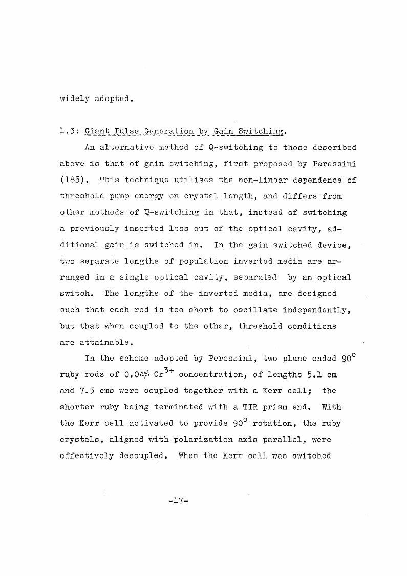
1.3: Giant Pulse Generation by Gain Switching,An alternative method of Q-switching to those described
above is that of gain switching, first proposed by Peressiiii (185). This technique utilises the non-linear dependence of threshold pump energy on crystal length, and differs from other methods of Q-switching in that, instead of switching a previously inserted loss out of the optical cavity, additional gain is switched in. In the gain switched device, two separate lengths of population inverted media are arranged in a single optical cavity, separated by an optical switch. The lengths of the inverted media, are designed such that each rod is too short to oscillate independently, but that v/hon coupled to the other, threshold conditions are attainable.
In the scheme adopted by Peressini, two plane ended 90° ruby rods of 0,040 Cr '*’ concentration, of lengths 5.1 cm and 7.5 cms were coupled together with a Kerr cell; the shorter ruby being terminated with a TIE prism end. With the Kerr cell activated to provide 90° rotation, the ruby crystals, aligned with polarization axis parallel, were effectively decoupled. When the Kerr cell was switched
- 17-

the system produced single giant pulses of pulsewidth 25 nsec, with powers up to 30 MW.
A similar device, using two rods (lengtte 4 cm and 5 cm) of neodymium doped calcium tungstate coupled with a rotating prism was reported in 1965 by Olay and Findlay (63). In the case of a 4-level laser, the non-linear dependence of threshold pump power,on crystal length can be derived from the work of Yariv (245). Single giant pulses of halfpower pulsewidth 30 nsec and pulse power'*‘2.5 MIV were produced.
Both these systems described were capable of producing a large number of shots without a drop in peak power. Another advantage was that since threshold conditions depended on the inherent reflectivity of the plane anded rods, the necessity for the use of antireflection coatings was obviated. However, the additional reflecting surfaces within the resonant cavity, in both systems, may be the cause of some loss; this could have been avoided by the adoption of Brewster angled surfaces.
As will bo described more fully in Chapter 4, the design of the present system differs in several respectsfcom
those of Refs,(l85) and (63), Ruby rods of lengths varying between 7.6 cm and 15.2 cm, of 90° orientation, and 0.050Or^^ concentration, with Brewster angle end faces were used.
These were coupled by means of a Brewster angled rotating
- 18-

prism, with a single optical cavity hound hy two end reflectors. Different combinations from a large selection of the latter were used at various stages of the investigation, but the final types adopted wore three plate optically contacted resonant reflectors, one plate of which was a Brewster angled wedge. The system was aligned in such a manner that the outputs from the two resonant reflectors, were parallel.
1.4: Effect of Variation of Temperature on Laser Action in
Under optimum conditions laser action in ruby occurs at the peak of the line, the wavelength variation of which, in absorption and fluorescence, with temperature, has been known for a long time (98). More recent measurements of this variation with temperature by observation of the fluoresence of ruby, and of the laser emission frequency are in agreement (10,202,242,76). Prom Wittke's measurements (242) the peak of the R^ line of ruby varies from 6934% at 77°K to 6958% at 500°K; near room temperature the variation is 0.065%/deg. The width of the R^ line also varies with temperature (204,242,143,76,9) decreasing rapidly from 16% at 500°K to 0.03% at 4.2°%.
Since the width of the absorption line is simply re-
- 19-

lated to its peak value, as the linewidth narrows with decreasing temperature, the threshold condition for oscillation decreases, \7ittke (242) has measured the quantum efficiency of th line as a function of temperature and found that it varies between 1.0 at 77°K to 0.1 at 500°K. However,Burns and Nathan (56) have pointed out that the fluorescent efficiency up to 500^K js hdependent of temperature, if one accepts all red radiation emitted by the ruby. It is the spectral distribution which changes, and the fraction of radiation emitted in the R^ and Rg lines which decreases with increasing temperature. In a fairly recent publication. Nelson and Sturgo (ISI) have made detailed measurements of the radiative efficiency and absorption cross-sections as functions of polarization and temperature.
The effect of a decrease in temperature on de-excitation looses, principally superadianoe, has been estimated by Masters (165, 167). This mechanism, which results in the depopulation of high gain systems by amplification of the spontaneous emission is strongly temperature dependent. This form of inversion loss also depends on the length of the crystal, and has led to various efforts to segment the ruby rod, using as isolators, liquid or film organic dye absorbers .
- 20-

1,5: Spectroscopic Techniques Employed in Laser Research.Many spectroscopic techniques have been used in the
development of lasers and in the new fields of research which they have stimulated. Well knov/n interference methods have received fresh impetus; to mention but a few applications, the Tv/yman Green interferometer is used for the determination of the quality of optical resonator components, the Mach Zchnder interferometer in plasma diagnostics and the measurement of coherence length.
Ill particular, the demands of the new laser sciences, together with those of plasma physics and the solar and astronomical sciences immediately took advantage of the improvements made in high resolution spectroscopy (227),This progress has mainly been in the fields of high resolution gratings, generally of echelle type (224), and in multiple beam interferometry (117), The latter has been assisted considerably by the improvements made in the surface flatness of Eabry-Perot plates, and in the development of high reflecting, lov; absorption, multilayer dielectric coatings. The echelle and the Eabry-Perot are probably the only two instruments capable of achieving resolving powers
5in excess of 10 . Although theoretically the Lummer Gehrcke Plate could also provide the same resolutions, many practical difficulties inhibit its use. Eor specific requirements,
- 21-

when resolving powers in excess of 10^ are needed, the spherical Eabry-Perot (EPS) would appear to be the only applicable instrument.
However, for many laser applications a resolution of 10^ is sufficient. In comparing the plane Eabry-Perot (EPP) with the echelle for a. given resolution (4-6) the former is about two orders of magnitude more luminous, a considerable advantage at the ruby laser wavelength where most photographic emulsions and photocathodes are relatively insensitive. The echelle however, has the advantage that an extended spectrum may be photographed at high resolvance in a single exposure, whereas the free spectral range of an EPP is inversely proportional to its resolving power. Eor the measurement of laser beam linewidths, and the detection of many non-linear optical effects, a large free spectral range is not required.
The introduction of the spherical Eabry-Perot by Connes (68, 69), has enabled, the direct spectroscopic observation of the axial and off-axial modes of solid state lasers (106,47, 48). At high resolving powers, this instrument has several distinct advantages over the EPP. The comparison of these two interferometers at high resolving powers is dealt with in some detail in this dissertation.
Photoelectric beat techniques, achieving much higher
—2 2—

resolution, have been used with considerable success in spectroscopic analysis of C W lasers, but great care is required in their application to pulsed lasers.
1.6: Non-Linoar Q-ptical Phenomina.OnG of the most interesting applications of the laser is
in the investigation of the non-linear interaction of light with matter. This field of optics has expanded prodigiously since the advent of lasers, primarily as a result of the intense electromagnetic fields, and high degrees of coherence, manochromacity, and directionality afforded by laser light.To therefore attempt a complete review of the subject is beyond the scope of this thesis. There are, in any case, a number of excellent review papers on non-linear optical phenomena (92,226,243) as well as several comprehensive theoretical treatments, both in classical and quantum mechanical terms (16,237,31,32,33,34,35,36,186). Further discussion will thus be restricted to those regions of the subject of immediate interest, with which the laser system here described could be associated; that is, sum, difference, and second harmonic frequency generation and various other optical mixing processes. Reference to such non-linear effects as parametric amplification, self-focusing and trapping of laser beams, stimulated Raman, Rayleigh, and Brillouin scat
- 23-

tering, and other multiphoton processes will have to be omitted. A recent paper reviewed these topics with particular emphasis (172),
Since the first non-linear optical effect to be identified with laser light, that of second harmonic generation (SHG), was observed in crystalline quartz (91) in 1961, numerous experiments have been conducted to detect the same and similar effects in other piezoelectric materials. Measurements of the relative efficiences for SHG in various •crystals (200) soon showed that ICH PO^ (EPP) and PO^(APP) generated the largest second harmonic outputs. Even so, the efficiency of generation of ITV light at 3470%. was still '-'10"^.
Significant improvement of this efficiency is obtained in anisotropic crystals by choosing a direction of propagation of the laser beam, such that the ordinary refractive index at one frequency is equal to the extraordinary refractive index for the other (99,138). With this socalled "phase matching" technique, efficiencies as high as 30-350 have been achieved with unfocused laser light (14). Saturation effects at high powers and for long crystals have been considered by Wang and Racette (236). These aspects of SHG have been studied theoretically in some detail by Kleinman (127,128,129,171).
- 24-

Prom Kloiiiman’s theory it is apparent that the same non-linear process that renders SHG-, also accounts for sum and difference frequency generation. This will be discussed further theoretically in Chapter 3, and in Chapter 8, where the successful sum frequency generation in ADP of the two tunable frequencies of the laser system is described in detail.
1.7: Non-linear Optical Effects in Plasmas.The development of a two frequency output laser system
of the type described in this thesis, enables the generation and detection of certain non-linear optical phenomina in plasmas to be brought into the realms of experimental realizability. Amongst these is the resonant excitation of longitudinal plasma oscillations by the non-linear mixing of two laser beams, proposed by Kroll, Ron and Rostoker (l32).
On the basis of theirs, and others calculations (196, 197,176,27), a feasability study incorporating the expected characteristics of the two frequency laser system was attempted (45). A recent publication proposed another method of approach (135). However, this depended on the development of a Kerr cell travelling wave line capable of producing a time varying frequency shift. As with light mixing experiments in crystals, optical mixing in plasmas is an effect
- 25-

essentially depending upon coherence.While in the case of crystal mixing, the well organised oystal structure permits large scale volume effects over a large range of sum and difference frequencies,in a plasma,the coherence volume and density are both much smaller,and also the generation of plasma waves only occurs when the difference frequency approaches the electron plasma frequency.Furthermore, the generation and detection of these resonant plasma oscillations is hampered by collisional and Landau damping effects(220) on the amplitude of the plasma wave and by the effects of convective non- linearities (133) on the plasma oscillation,Detection of the resonant plasma oscillations would be made either by direct microwave detection or from the observation of scattered light from the two original beams,or from a third laser beam. From the study made,as will be enumerated in Chapter 3.4,it would appear that generation and detection of the effect with the use of a two frequency output laser should be possible. Stern and Tzoar(222) have recently reported the direct detection of longitudinal plasma oscillations excited by two microwave sources,whose frequencies differed by the plasma electron frequency.The possibilities of observing the effect at lower plasma densities than proposed in Ref. (132),using infrared lasers has been discussed (206). Optical mixing at frequencies other than the electron plasma frequency, in
- 26-

plasmas with an externally applied magnetic field, has also been considered (199)?
Several other non-linear optical effects in plasmas have been investigated theoretically; elastic light by light scattering in a plasma (187,188,79,80) (though this was at first confused with resonance scattering (60)), sum and difference frequency generation in a plasma (124,125,198, 67) and the observation of stimulated Raman scattering in a plasma (27). The generation of the second harmonic and beat frequencies of two microwave oscillations in a low density plasma has been detected (221).
1.8; Simultaneous Two Frequency Laser Output.It is evident from Chapter 1,7 and will be further in
vestigated in later chapters, that a tunable two frequency output giant pulse laser system would have considerable applications in the field of non-linear optics. The development of such a laser system may be approached from two different directions; the synchronisation of two separate laser? operating at different frequencies, or the operation of a single laser system which oscillates at two frequencies.
The problem of the synchronization of several Q-wwitched lasers has received close attention by several research groups. Nguyen van Tran and D. Kehl, synchronised a ruby
- 27-

laser and a neodymium laser,by colinearizing part of each optical resonator and employing a roof top prism as a common Q-switoiling element (182) . Opower and Kaiser have reported the synchronisation, to within^ 3 nsec. of the light beams (r^io ns pulsewidth) emitted from two passively switched ruby lasers (184)• This was achieved by employing the output of a third Q-switchcd laser of moderate power to bleach the liquid dye solutions simultaneously. From spectroscopic measurements made on the output of the two lasers, it is found that when they are switched by the third laser, their emission frequencies are locked to that of the third laser, which bleaches the absorption bands of the dye solutions at its own emission frequency. Similar results have been reported by Gregg and Thomas who synchronised the outputs of five laser systems by the same method (103). Though there would be no apparent limit to the number of laser systems which could be switched simultaneously in this way, since the oscillating frequencies of the lasers are locked to that of the triggering laser, multiple frequency operation would not appear to be possible. Extra—cavity methods of frequency shifting, utilizing the Doppler effect in a Kerr cell travelling wave line, for instance (l34), could, however, be employed with the above systems.
Simultaneous giant pulse laser operation at two fre-
- 28-

quencics has been reported in a single ruby crystal (58), by forcing the latter to oscillate at the peaks of the and R2 fluorescence lines (6945% and 6929%). This laser cavity was rotating prism Q-switched and contained a thermally or mechanically adjustable biréfringent crystal which rotated the plane of polarization of the R^ line emission by 90° while leaving that of the Rp line unchanged. Though this system has the advantage that the two frequencies are generated in the same optical resonator, they are orthogonally polarized, and frequency tuning could only be achieved by employing
5+a second ruby rod. The operation of a ruby laser and a Nd glass laser in a single resonant cavity, Q-switched by a rotating prism has been recently reported (100). The output powers recorded were^^2.5 MW at 6943% a n d 10 OT at 1.06/^ .
The laser system described in this thesis combines many of the capabilities separately exhibited by the above devices. Not only does it provide two simultaneous parallel pulses with powers in the tens of moggawatt range, but also each pulse may contain two frequencies, the wavelength separation of which is tunable from 1-5%. Additionally, the relative powers, of the two pulses, and the relative intensities at the two frequencies are variable.
—29“

CHAPTER 2 : SOME THEORETICAL ASPECTS OF GIANT PULSE LASERS.
2.0: Gi.ant Pulse Lynamics.The inclusion of a time varying loss or gain mechanism
into a laser resonant cavity, enables the generation of extremely high powers emitted in single short ’giant’pulses,
The complete theoretical description of this technique, which is dependent on the behaviour of many complicated, rapidly varying processes, has yet to be attempted: consequently^ existing analyses have resorted to simplified models of the dominant mechanisms involved. By formulating rudimentary rate equations for the population inversion and photon density within the resonant cavity, and by approximating the temporal change of the cavity Q, realistic predictions of the principal characteristics of the giant pulse output may be made. These are such parameters as the energy and peak power radiated, the rise and decay 'times of the light pulse, and the required buildup time between switching and the evolution of the pulse.
In the following, the broad outlines and general conclusions of the dynamic rate equation analysis are discussed. Particular reference is given to the time behaviour of the cavity Q switching terms, and the consequences and relative merits of ’slow’ and ’fast’ switching on the output of a
—30—

laser system are discussed#The form of switching known as gain switching, as
mentioned in Chapter 1.3, is considered analytically. A brief outline is given of the approaches of several workers to the problem of investigating the nature of optical cavity modes in a Fabry-Perot type resonator. From this, axial and off-axial modes are distinguished.
2.1: Simplified Theory of Q-Modulation.The theory outlined here follows that developed by
several workers, (110,234,15,173,201,93) and to a large extent utilizes the same notation.
Representing the photon density at frequencyujby^, the population inversion per unit volume by (/= /V. (where
A/ A/^-= number of active ions/unit volume) and neglecting the effects of all processes which are slow in comparison to the formation of the giant pulse, the simplified * rate equations for^andA/with time may be deduced as follows.
Consider initially the case of ’fast* switching,when the change in cavity Q is represented by a step function, such that no significant change in population inversion takes place during the switching process. The lifetime of a photon within the resonant cavity of length L, is X — where t-,-L/c , The fractional photon loss per single
- 31-

passage of the resonator, ^ where (n T<,Rg the reflection losses, incidental internal losses. The cavity Q-t^JZ is smaller than that due to diffraction losses.
Prior to the formation of the pulse, when the laser rod is optically pumped, the loss coefficient being ^ ^
the population inversion rises from - A ^ t o t AAand the photon-rdensity tojp . When the cavity Q is rapidly increased by
reducing the loss to ^ , at time t ' O , photons travelling the length t of the crystal are amplified at the xate per transit time, t, v/here gain coefficient cC - A'VA/ o being the absorption coefficient of unexcited material. The loss rate of photons from the resonator is ÿ /% •
' (If - 4 ) fThe inversion decreases as the rate
_ _ ?-X.£, T ( 2 - 2 )fl(t t, ^
since /V decreases by 2 for each photon emitted. By normalizing n,~/'•///Vg j 0 = introducing the threshold inversion
and then changing the time scale to make TT - the unit of time. Then
I t ~ (2 - 3)
^ — 2rx<p (2 - 4)
- 32-

As the inversion falls from ri to rij , the photon density rises several orders of magnitude from <2^with time con
stant t , t o a peak value 0^ , before decayingwith the natural cavity decay time X .
The first integral of the above equations gives information concerning the physical nature of the giant pulse
»as a whole. It follows that
SiP - ~JL ( 2-5)cLn 4
and thus (p (2 - 6)Since % and are negligibly small
The total radiative energy in the laser is
8 - I (fl. ( 2-8)for volume of active material V .As generally > 4 . j. 01;and by expansion of the logarithmic term of the equation above, then
£ - (n^/ae}C>u (2 - 9)
The peak power is related to the peak photon density at Cl-flp and the cavity decay time T
P = w/i: (2 - 10)
-35-

and the peak effective output power is Hence
^ * 2 - ('V •In order to obtain4 s,nd n as complete functions of C ,
and thus expressions for the pulse buildup time between switching and evolution of the pulse, and the approximate duration time of the pulse, complex integration of t, as a function of0 and/% , in one region by machine computation, is required. This has been done for the case of fast switching, rendering results in good agreement with practice (234). Theoretical predictions on the optimisation of the output by adjustment of the loss rate for a given population inversion have been made for this case (168).
Wang (235), has shown that this same approach may be adapted for a moderately fast switch where, now
Ci^) representing a ramp function.The more general rate equations of Vuylsteke (233) have
been solved by computer for slow switching, simulating the rotating prism switch, by utilizing a cosine function switching term (169). Hellwarth (110) considering slow switching assumed a switch function t obtained resultsexhibiting multipulsing where, as the switching became
— 34—

slower, the pulses became broader, and less intense both in peak and integrated intensity; experimentally confirmed by Basov et al (25).
However, high power single pulse outputs from lasers operated with slow switches, such as rotating prisms, may be obtained by optimising the resonant cavity length with the speed of rotation of the prism (15,192, 28), Arecchi et al (l5) in their experimental and theoretical analysis, having derived the same rate equations as above, made detailed estimates of the temporal behaviour of the loss coefficient. The cavity losses as a function of prism alignment were obtained experimentally, and also by analytical interpolation using the theoretical relation between maximum population inversion and pump energy (216,97). They found
= (t/ti - / h + b (2-13)where %(t) is minimum when t -t$ > assuming as timeorigin, the point when threshold conditions, controlled by the rotation of the prism, of period T , becomes equal to the population inversion, ts may be expressed in terms of ( ; b (C/) is constant, dependent on the cavity parameters.
I'Then - X , the photon lifetime in the resonant cavity, the final relative population inversion drops below the minimum threshold value, and all the available energy is
- 35-

thus released in a single pulse. If <. f the efficiency of the process is reduced and the pulse will be consequently of smaller amplitude. V/hen tj > T the pulse occurs before the minimum threshold condition is reached, thus allowing the possible formation of further pulses.
2.2: Theory Associated with Gain Switching.Instead of producing giant pulses by switching the
cavity losses from an initially high value to a lower one, similar results may be achieved by switching additional gain into the cavity, as reported in Chapter 1,3. This technique utilizes the non-linoar dependence of the threshold pump energy on crystal length, which may be shown from the following.
From the general rate equations for a three level laser system, at threshold, it may be shov/n that
(2 - 14)AG VV/j 'i
where, for ruby, - probability of spontaneousemission from the state to the ground state, and K 3 isthe threshold pump rate from the ground state to the ff levels,
Henco the threshold inversion
(I - )/i ' )-36-

From Chapter 2.1.^ rip % /cAo (
The incident radiative flux density Pp at threshold
4 - W,3K (2-16)where and cf are the mean frequency and the integrated absorption cross-section for pump radiation, respectively. Hence for a cylindrical ruby rod of length t and radius r , and assuming a square pumping pulse of length Ip , the total pump energy required for oscillation threshold
ot 11, I a - X 4 i ) jIt can be seen from the above equation, that for a
given loss coefficient ^ , the threshold pump energy increases asymptotically as t is decreased to . For valuesof ^c/othe threshold condition for oscillation is never reached.
Thus in the gain switching scheme, tv/o ruby rods are arranged in a common optical resonator, separated by an optical switch. The ruby rods are such that, when decoupled by the optical switch, threshold conditions are unattainable. However, when the two rods are coupled together the total length of ruby is such that the threshold pump energy is low. The system described in this thesis, though different in some
- 37-

respects from the original device of Peressini (185), may be classified as a gain switched system, in that, v/hen the Brewster angled rubies are decoupled, oscillation is precluded. Additionally when the system is operated in the two frequency mode, there is some evidence to suggest that gain switching is required. That is, for one of the oscillating frequencies, if not both, laser oscillation is inhibited without some additional gain from the other ruby rod.
2.3: Modes of a Resonant Cavity.The use of the plane Pabry-Perot interferometer as a
multimode resonator for optical masers was first proposed in 1958 (202). However, it was the work of Pox and Li (90) which showed that cavity modes, in the sense of self-re- producing field patterns, exist for an open structure such as a Pabry-Perot interferometer. This was done using a self- consistent field analysis, based on Huygcn’s principle, with the aid of a computer. Other theoretical investigations of the same problem, either using Maxwell’s equations (212), or a classical pertubation theory (20,21) led to essentially the same results.
Por an optical resonator to support high Q modes, certain basic criteria must be satisfied (246). There must exist a family of rays within the resonator for v/hich mul-
-38-
tiple reflection from the two reflectors does not result in appreciable "walk off". Additionally, the loss from diffraction effects must be low: i.e. the angle subtended by one reflector at the other, must be greater than the angle of the far field diffraction pattern of a plane wave originating at, and with the dimensions of the other reflector. That is, the Fresnel n u m b e r , — L ^ f where tx z radius of the reflectors.
Barone (21) found that if q , where is thevariation from 'parallelism of the end reflectors, then the transverse modes of the cavity may be characterised by Bessel functions. Por most solid state lasers this is not the case, and the transverse mode structure must be described by more complicated functions derived from analyses of non-confocal resonators (39,40). However, to illustrate the difference between axial and transverse modes, the simplifying assumption of the Bessel function solution will be made.
The resonant frequencies of a cylindrical laser of radius r may be obtained from the expression for the vector potential as
I X i f 1 (2 - 18)[ n J ■ L. / A /
where the /nlh zero of the Bessel function of order t .The longitudinal, or axial modes of the resonator are
-39^

characterised by the integer (largo) a , where i m. - O , and defining y = O . Thus two adjacent axial modes are separated by f r e q u e n c y , whence
- Z 3 ^ ^Irry (2 - 19)1 L C c
v = C. / 2 LFor a laser cavity of length 1= 100 cms, then A/^ 150 Mo.Thus the spectral output of normal lasers will be several axial modes spacings wide, though considerable effort has been exerted recently to obtain single mode operation.
Transverse modes are produced v/hen , Thefirst transerse mode in the cylindrical case is that for which i-O , rn - / . The separation of this mode from the axial mode is given by
V , - V ^ = X 4 c 2 < . (2-20)Srr^r^
which for a ruby rod of diameter of 1 cm, gives a frequency separation of^200 KG. The transverse mode separation increases with higher order modes.
However, in the case of ruby lasers, this treatment of the transverse mode structure is complicated by several factors. These arise due to inliomogcnous effects within the crystal, temperature effects, and effects associated with non-ideal cavity conditions. Additionally, more complex modes, associated with the quality, shape, and optical pump
— 40—

ing arrangement may also exist. In general to distinguish these modes from axial modes of the cavity, they are classified in this report under the term of ’off axial modes’. High resolution spectroscopy of the outputs of giant pulse lasers, reported in this dissertation, has enabled the direct observation of off axial modes.
- 41-

CHAPTER 3: THEORETICAL OUTLINES OF SOME NON-LIIIBAR OPTICAL PHENOMENA.
3.0: Non-linear Susceptibility.The intent of the following chapter is not to give a
detailed analysis of non-linear optics, but merely to provide the theoretical framework for optical effects considered in this thesis. These are sum, difference, and harmonic frequency generation in anisotropic crystals, and certain non-linear optical effects occurring in plasmas.The treatment is by no means rigorous, as lack of space prevents this, but only serves as an indication of the underlying principles, approach and conclusions of detailed theoretical analyses.
The theory of wave propagation in non-linear media depends on no new fundamental theoretical concepts, and indeed may well have been developed with purely classical methods by the early postulants of electromagnetic field theory, had they had the stimulation of the experimental findings of today. The properties of non-linear materials may be described by expanding the polarization^ in a power series in the field E .
P - X f - X z f E (5-1)Where X, is the normal linear susceptibility and % the
lowest order non-linear susceptibility.
— 42—

In the following, tho non-linear polarisation terms responsible for the second harmonic and sum frequency generation processes are examined. Phase matching is considered. Finally, the theory of optical resonance mixing in a plasma is surveyed.
3.1: The Lowest Order Npn-Linoar Polarization.Since the non-linear susceptibility in equation (3-1)
r WL
to which it gives rise, becomes of consequence only when the highly coherent fields generated by lasers are considered.For instance, the lowest order non-linear polarization at the second harmonic frequency (2*),) due to the presence of a field
(Lt jy(Lk,-r - iui) , may be writtenr- i(2ui) E, £, (3 - 2)
In general, % is a third rank tensor, whose elements arerestricted by the symmetry of the non-linear medium. It vanishes for any system with a centre of inversion.
Dug to the dispersion in the optical media, the second harmonic wave r - 2ut) will in general travel witha different propagation velocity to the fundamental, and hence
Zk.(u) (3 - 3)Thus the second harmonic wave and this source will get out of
— 43—

step, and there will he a 180° phase shift with respect to the second harmonic after a distance for which
( A- - 'I ’ coh ~ (3-4)Expressed in terms of the refractive indices for the propagation direction of the second harmonic and fundamental
LjC'f a i Z u j ) - n (3-5)where is called the coherence length of the wave.
Therefore, the power absorbed from the second harmonicwave
- W ( lj) = W) = 2<U Im g V b s u j ) (3 _ 6)
will alternate in sign. V/hen the second harmonic ha,s been generated, consequentially decreasing the power of the fundamental wave, the harmonic will be reabsorbed and the fundamental recreated etc.. Variation of the optical thickness of the non-linear media by rotation of the latter demonstrated this interference effect (158).
3.2; Phase Matching.The effect of the difference in phases of the second
harmonic and fundamental waves, mentioned in the previous chapter, may be overcome. The most effective method is that of phase matching (99,158). By optimally orientating a sufficiently biréfringent crystal, it is possible to achieve an index match betv/een the beam polarized in one direction
— 44—

and its fundamental polarized in the other direction. Birefringence is then balanced against dispersion. This is done by constraining the fundamental waye to be an ordinary ray and its harmonic an extraordinary ray, or visa versa, depending on whether tho medium has positive or negative birefringence. Then, it is possible to make the phase velocities of the two waves equal, by choosing a particular angle (Om) between the direction of propagation and the crystal axis where,(243),
(3 - 7)
Using this technique conversion efficiencies in excess of 30fo have been reported with the use of giant pulse lasers (14).
3.3: Conclusions from Kleinman’s Theory.In this chapter the main assumptions and conclusions
of rigorous treatments of second harmonic generation, and in particular that due to Kleinman (i29), are reviewed. This theory is described in classical terms, based primarily on tho non-linear Maxwell’s equations and is an extension of previous theories for lossless anisotropic media. It involves the determination of the nature of the electromagnetic field arising from the production of the non-linear polariza-
- 45-

tion in equation (3-3). This field is derived fromthe inhomogcneous vector equation.
E - = A L r ç ' l ^ / r ' - l 2 o )
whore Iz is nov/ the field generated by the non-linear polarization, and is a linear function of it.
The case of phase matching is considered, though the effects of optical activity and absorption are neglected.All coherence effects are treated exactly, and it is shown that there is a change in the behaviour of the energy flow at the second harmonic frequency, expressed by the time averaged Poynting vector S along the direction of propagation.gThis change becomes apparent as the length of anisotropic media, f becomes comparable to the "coherence length for the pencil", defined as,
$,4 (3-9)whoro/6 is a mismatch factor incurred because of the finite divergenceAof the laser beam. ( 4 x 10^ cm*” ). Thepencil of light contains many waves, with widely varying :
is a suitable average over the distribution of inthe pencil. Tho two limiting cases are(a) Thin crystal case ^ (3 - 10)
< 5 > j G
—46—

(b) Thick crystal case t » l-cch (3 - 11)
<-'S> -the phase matched index of refraction.
£.1. can thus be regarded as that crystal thickness at which < S*>changes from being quadratic to linearly ' dependent on the crystal length. Vliether a crystal is thick or thin depends on the beam divergence of the laser beam.
The non-linear susceptibility \,p2Cj) may be transformed from a (3 x 3 % 3) rank tensor to (6 x 3) tensor,
as for the piezoelectric tensor.Hence it may bo shown that the Poynting vector for the
intensity of second harmonic is
<S> - 12)
where is tho intensity of the fundamental beam. depends on whether the crystal is thick orthin. initial
With two frequencies,and present in the/electric field strength, then expressions may be deduced for the non-linear polarizations at the second harmonics Zw. andZwc , and at the sum and difference frequency (W, + ) andrespectively.
It can easily be shown that expressions for F andP*^(L^-U%) are similar to those of F''(2wjand ^ .
- 47-

For an initial field£ = E, k.pT- (3 - 13)
Then
andl u . . ) E , "<(’A ^ ^ _ 2^)
Therefore the analagous expression for the intensity at the sum frequency, corresponding to (3-12) is
j/w.a74SiaV,Fi',6tA) (3 - 1®>L_ ^
That is, in the simplified case of single mode fundamental fields, of two frequencies, and CJj,, the efficiency of sum frequency optical mixing is four times greater than that of the second harmonic process generating frequencies and.2k' (the additional assumption is also implied that the two frequencies are sufficiently close together such that the dispersion relations, and thus the value of 6-,, are the same in both cases).
V/hen this treatment is applied to the case of optical mixing with a ruby laser operating at two frequencies, the relative efficiences of the sum frequency generation and second harmonic processes are modified, due to the multimode nature of the laser emission. This will be discussed further
_ 48_

in Chapter 8.
3.4; Optical Mixing in a Plasma,As mentioned in Chapter 1.8, the non-linear mixing
of two laser beams in a plasma was considered theoretically by Kroll, Ron and Rostocker (132).
Prom theirs, and others' analyses, in order that enhanced longitudinal electron oscillations be generated in a plasma, of temperature kT and electron density n by the non-linear mixing of two monochromatic electromagnetic beams
~ i. U,t.} and the followingconditions, must be met (45).
The difference frequency should correspond to the electron plasma frequency -(4H n C Y m ) .
U, àio à u << Ofi« CJ, ; OiPor collective excitation I
- k. = k A k « k (3-17)where - Debye length - k r/4_n TIn order that the cold electron plasma equations may boemployed
thermal electron velocity.Por low temperature plasmas, the perturbation assumption is valid so long as the non-linear resonance field is much less
- 49-

than the transverse fields. That is ( E, j ) must not he so largo as to make 4-i % ^ A of the same order as jF,, &-i • I is the Landau or collisional damping which ever is dominant, is the resonant density fluctuation.
The scattering cross-section is then proportional to
^ .) afk -f - k j ] I Û k w P I ] (3 - 19)where j (k z longitudinal dielectric constant
= [| -t-T'' (3 - 19)The choice of a suitable plasma is rather limited.
Thomson scattering and Stark broadening measurements made ona pulsed hydrogen arc at Culham Laboratory (75) have given
14 “ Tvalues of H.-9 x 10 cms and K ( 2.2eV . If the anglebetween the two beams is chosen such that k\p = 0.27 an angleof 4.6^, then Landau damping isJ,j=5.3 x 10” and collisionaldamping Q = 2.3 x 10 Per detuning due to the variation ofdensity to be of t?ic same order as dissipative effects thenSn.jf] <T 3 X lO^ovcr the scattering volume ^10~^ cm^. Thisimplies that the spectral width of the laser be narrow enoughto allow A O j / 1.5 10** , i.e. = 0.06%. With these con-
—11ditions the ratio of scattered to incident light is **'5 x 10" for f,, £- -10* V cm"?’
Recently Boyd (42) ho.s shovm that there is a transfer time f characterising the transfer of energy from thetransverse to the longitudinal mode.
-50-

5 ’ T S / \j (3 - 20)
For tiiGparanoters disousscd above, ^ 50 nsec. Hence the existence of such a term night prove to be a serious limiting factor on the experiment.
-53U
CHAPTER 4: THE DESIGN AND TECHNOLOGY OE THE LASER SYSTEM
4.0: Adoption of a Single Resonator Cavity.The need for a high power laser capable of generating
two frequencies simultaneously has already been discussed.Tlie development of such a system can obviously be approached from several possible directions. As has already been indicated (Chapter 1.8) systems dependent on the synchronization of two separate lasers, operating at different frequencies, suffer from loss of simultaneity. IVhen designing the present device, it v/as felt, and it would still appear to be true today, that, bearing in mind the present state of. the art, the greatest possibility of achieving complete simultaneity of two tunable output frequencies, would be to incorporate two active media in a single resonant cavity, and employ a common Q-ewitch. If, in addition, this latter switching mechanism v/as such that it prevented one ruby rod from lasing without additional gain from the other, the possibility of the two frequencies being emitted simultaneously would be even greater. This argument naturally led to the adoption of the gain switching mechanism.
A rotating prism was chosen as a Q-switch because at the time it was the only reliable switch which did not introduce undesirable spectral characteristics into the laser
- 52-

emission. Other spectrally 'clean* optical switches are nowcryptocyanine
available. Towards the end of the project/ dye cells were substituted for the rotating prism as a Q-switch, as m il be described in Chapters 7 and 8.
4.1: Choice of Main Components.In order to satisfy the high power and narrow spectral
width requirements demanded in the field of non-linear optical effects, and to utilize to the best advantage the relative responses of photoelectric detection devices, ruby rods were chosen as the oscillation material. The two rods of the laser system were chosen from a selection of four rods, of lengths 3", 4”, 5”, and 6", all of 3/8" diameter, O.Obi' Cr^^ concentration, 90° orientation of the crystal o axis to the rod axis. At that time, three grades of linde^ ruby wore available. Developmental (Czochralski),S.I.Q. (lornouil) and Standard quality. The second grade, S.I.Q. was chosen, partly for economic reasons, and also because of its well proven ability to withstand high power densities. The 6" rod had polished sides, whilst the others all had roughened sides to reduce the possibility of the existence of spurious modes, and additionally to produce more uniform pumping within the crystal i.e. it destroys the focusing action of a polished optical cylinder. All tho end faces of
- 53-

the ruby crystals were cut at the Brewster angle {2S 3(f) to the cylinder axis, with a surface flatness of A/lO and parallelism tolerance of 10 minutes of arc. Although the adept ion of Brewster angle end faces created difficulties in the alignment of the system, the resulting advantages fully countered these. Foremost among the latter, was the reduction of intra-cavity losses and superradiation effects within tho resonator cavity by the elimination of all reflecting surfaces, and the consequential obviation of the use of the anti-reflection coatings, which have shov/n on occasions to be incapable of withstanding high power densities over a reasonable period of time. Also, for a laser system, on which spectroscopic studies on the characteristics of various mode selecting resonant reflectors was going to be performed, the elimination of all reflecting surfaces which may influence such mode properties, was a necessary prerequisite .
Optical pumping of the ruby rods was achieved by the employment of linear Xenon flash-tubes of appropriate length, suitably arranged with the ruby rod inside an elliptical optical pumping cavity, a design which utilizes the focusing properties of an elliptical cylinder with highly reflecting internal walls. This choice of pumping scheme was made in preference to the other popular method, originally used by
- 54-

the pioneers in pulsed lasers (154, 64), the soaalled'close coupled'pumping system utilizing helical flashtuhes, for several reasons. The latter method which depends on single pn-'::- Tumping and. in which only part of the flash light is dJrooted towards the ruby, is thus loss efficient than a focused optical cavity, and therefore correspondingly higher input energies arc required. Additionally, the adoption of an ulliptically focused cavity facilitates refrigeration of the ruby more easily than for the close coupled system.
Normal methods of pumping ruby rods with linear flash tubes in an elliptical cylinder utilise the focusing properties of the ellipse by arranging the flashlamp and ruby rod to 00 situated at the two respective focii (61,41). This has tho disadvantage, especially with rubies with polished sides, that there is a non-uniform distribution of pump light within the crystal, the maximum pump energy being in tli.. centre. The scheme adopted here, the so-called "exfocal" pumping design, first proposed by Ross (i93), abandons the principle of imaging the source in the ruby. Instead, the ruby rod and flashlamp are situated on the major axis of the ellipse, between the focii and end points, as shown in Fig. 4.1. V/hen the light source is situated outside the major axis, and the eocentrioity of the ellipse is such that that part of the major axis between the focus and the end
■55'

Fig 4.1 : Optical Pumping Configurations in
Elliptical Cavities,
(a) Focal Optical Pumping.
(b) Exfocal Optical Pumping.

point is completely covered by the source, then the energy distribution along the axis is transformed to the opposite part of the ellipse, where the ruby rod is situated, with a ratio of 1:1. Unabsorbed light returns back to the source, whence it is reflected back to the laser rod. The pumping efficiency of this multipass configuration depends largely on the reflectivity of the interior walls of the elliptical cylinder, and on the accuracy to which the latter can be made (in this case-^lO inch). Considerable attention was paid to the former problem. It was found that the possibility of machining or polishing, accurate high reflecting elliptical surfaces from pure aluminium, is inhibited due to its soft nature. Finally a scheme was devised whereby thin (0.002 inch) stainless steel liners, were inserted as a close fit inside elliptical cylinders machined from brass or aluminium. These metal liners were first electropolished in a solution of orthophosphoric acid and glycerol, and then coated in an evaporation plant with a thick layer of aluminium, which was then oxidised. normal operation, these liners had a lifeof several hundred shots, and were easily replacable. The flashtubcs used in the system were either Thermal Syndicate T/E 6/60A or EGG EX-42A -3 and EX-45 -6.
The choice of material for tho rotating prism was given considerable attention. It was necessary to find a type of
-57-

glass of high optical quality and homogenity, as well as a glass which had a refractive index as near as possible to that of ruby (n=1.76) in order that the Brewster angles on the prism would irt be too dissimilar from that of ruby, consequently, making the two ruby rods nearly parallel for optimum alignment. From the work on laser damage thresholds in various glasses by Cullom and Waynant (70) and Martinelli (164), the prisms were made by Gooch and Housego Ltd. from selected dense barium crov/n glass (BBC) of S2 type (n - 1.62), which has a nominal life of,* 2 years before surface blemishes appear. Before this material became available, prisms of BBC of 84 and 86 types, which have shorter blemish free lives, wore employed. These prisms were found to have a considerable shorter working life in the laser system before damage became apparent, than the prisms of 82 type. Although discussion of the various types of resonant reflectors experimented with, is left to a later section, it should be mentioned hero, that the circular wedges incorporated in the optically contacted resonant reflectors were made of the same material as the rotating prism. Consequently, v/hen these reflectors were employed, the two laser outputs were parallel and in the same direction.
- 58-

A
4 /7 ///I
■o2
3"OI0)O)0)
u.£E E3a15yIJOE0)ÛevjO)

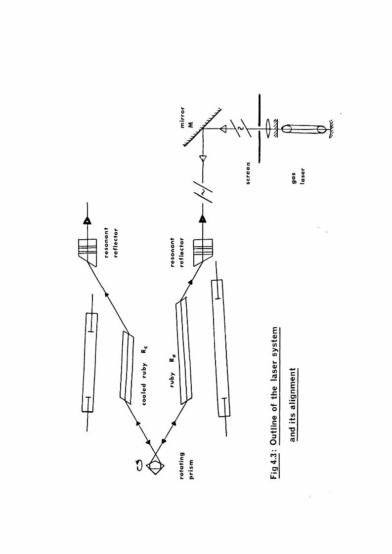
4.2: Design of tho Laser System.The experimental design of the system is shown schem
atically in Fig. 4.3. The ruby rods wure arranged so that the plane of polarization of the resulting laser light Wbs horizontal, thus all the Brewster angle faces v re in a vertical plane. Since there is a refractive index differential between the glass prism and the two rubies, the latter were offset from parallelism by a small amount. The glass prism rotated about a horizontal axis which was perpendicular to the mean axis of the ruby rods. By rigidly setting the prism in a balanced a,ir turbine, (constructed at A\WE, Aldermaston), speeds of up to 40,000 rpm were obtainable; although the normal operating speed v/as 24,000 - 30,000 rpm. The prism mount was set on a separate bench from that holding the ruby boxes, in order to isolate the latter from any vibrational effects. The ruby boxes were both mounted, with vertical and horizontal adjustment facilities, onto a single solid 1" thick aluminium table, which was rigidly fixed to a stable wooden bench. The aluminium table was so designed that the position of tho different lengths of rubies, and the end reflectors, could be varied, A photograph of tho assembly is shown in Fig. 4.4.
The mechanical design for locating the ruby rods within the pumping boxes deserves some explanation. In the case of
-60-
CO
Li.

the ruhy which was kept at room temperature, the ends of the rod were held in the end plates with thin perspex sleeves, to prevent mechanically stressing the crystal, and also to protect the end faces from being chipped in assembly. The design for the cooled ruby optical pumping box, needed considerably more elaboration as can be soon from Pig. 4.2. The ruby was mounted in two close-fitting brass holders, necessary for the cooling system (see later). These holders were thermally isolated from tho end plates by means of thin perspex sleeves and thin circular layers of asbestos paper. Since it was soon discovered that perspex carbonised when directly exposed to the flashlamp radiation, the insulative holder for the trigger wire was made of glass. The flashtubcs for both pumping boxes were isolated from the walls of the cavity by a small (O.OlO inch) gap and held in position with perspex holders. The thermocouple was fixed permanently in contact with the ruby by means of an Araldite plug which insulated it from the end plates. Its output was suitably displayed on a sensitive galvanometer. Both pumping boxes wore thermally isolated from the bench mounts and thick A1 table, which would act as effective heat sinks, by separating the boxes from their mounts with mica sheets, and the utilization of polythene fastening screws.
.-62-


4,3: Electronics Associated with Operation of laser System.The electronic circuitry required to charge, control,
and fire the laser system was of generally an orthodox nature, and because of such, much of the apparatus was available in the form of standard units which needed little or no modification.
The two independent charging units for the flash-tubes were fabricated specially for the project. Each consisted basically of a full wave rectifier bridge, charging to between 1 and 2.5 kV. a 580ywE capacitor, which wa,s connected in parallel to a 100/--H inductance in series with the flash- tube. ?.lien the flash-tube was triggered, between 190 and 1200 Jouleswere dissipated in the flash-tubos in a time 1msec defined by the time constant IZ = The effect
of pulse shapening on the threshold conditions wa,s studied by connecting a delay line in parallel with the flash-tube. Considerable pulse shapening was observed, but there was no discernable change in the threshold: this agrees with thetheoretical conclusions of Mace and MacCall (149). Also, since faster rise times are involved in pulse shapening, the life of the flash—tube is considerably diminished. Both charging units were earthed to the ground, independent of all other equipment in the laboratory.
A block diagram of the triggering circuit is shown in
-64-

Pig, 4.5. Por maxinun efficiency of tho laser system, the flashtuheswj«rc pulsed several hundred microseconds before the prism zeachoclthe hi^ Q position. This temporal control rosulW from a photodiode receiving an optical signal from a tungsten source reflected off the rotating prism, half a revolution before the latter passed through the lasing position. The— InV pulse from the photodiode (Toxas 2175)v&s first amplified. The speed of tho rotating prism measured with a rateneter which received part of the amplifier signal from the gating unit. When the laser vos to be fired, a -lOV pulse released by the push button from the pulse box. Was sufficient to open the gate circuit and permit-: one +10V pulse from the amplifier to pass through to the trigger unit. The gate w<s closed by the sucoæding pulse from the photodiode. The trigger unit had two -507 outputs, which
fed into the two delay units. It also served as a manually operated triggering unit when the laser system was operated in the relaxation oscillation mode with the prism fixed. After a suitable delay, such that the flash-tubes were triggered*^700^seco before the prism reached optimum alignment, the outputs from the delay units (+2007) were amplified to 12-3.5 1:7 pulses by means of two small pulse transformers located at the laser pumping boxes. These pulses pass down the small thin trigger wire adjacent to the flash-tube,
—65-

h-m
E0)U)>Sl/lk0>lA_0o
O(A3Q.oO)9)
lOO)

and short to earth through the latter, thus causing breakdown of the flash-tube.
4.4: Resonator End Mirrors.The very first lasers wore constructed using partially
or fully reflecting silver coatings on optically flat surfaces. These were soon superseded by multilayer- dielectric coatings. Tho invention of Q Switching techniques, and improvements made in growing longer and better optical quality rubies, ushered into laser physics a new era of vastly increased powers. As a consequence, dielectric mirrors had only a short life in such systems, before the high power densities caused serious deterioration to the reflecting surfaces. Because of this difficulty, and as a result also of the lower reflectivities generally required for Q-switched systems the adoption of single sapphire plates, and of multi-element glass plate resonant reflectors, has become more widespread. These have the advantage of possessing much higher damage thresholds and additionally when optimally designed, introduce mode selectivity into the resonator cavity. Recently, technological improvements have rendered the production of dielectric mirrors reputedly capable of withstanding power densities of several hundred
- 67-

In the analysis of the spectral output of this laser system, a largo variety of end mirrors have been tried. Dielectric mirrors of reflectivities ranging from--60^ to 98^ at 6943% on plane (surface flatness A/lO) and concave glass blanks were employed. Without exception, these coatings wore burnt within loss than ten shots of the laser with power outputs-^lOMW. Vdien longer resonator lengths were required, one of the end reflectors was replaced with a roof top prism, which effectively doubled the resonator length. At one time, the 3” ruby was cut with one TIE. end, but this soon became chipped and was replaced with a Brewster angle face.
Apart from the wedged optically contacted resonant reflectors,or étalons, shown in Big.4.3., a selection of glass optical flats of different thicknesses made possible the construction of several types of resonant reflectors having different mode selecting properties. In the more complicated of these mode selecting resonant reflectors, in which the optical distances between the reflecting surfaces wore arranged in some type of mathematical series, thin (8/<) plastic films stretched over metal frames, called "pellicles”, were also used as reflecting surfaces.
4r3 ; The Coaling System.In order to produce a change in wavelength of as
-68-

much, as 5% in the oscillating frequency of one of the ruhy crystals, it was estimated, from the work of Wittke (242) that the crystal would have to be refrigerated to a temperature of~ 200°K. Additionally, if the wavelength separation of the two frequency output was to be tunable, then the temperature of the crystal must be variable from 200^K to room temperature. Other factors were also involved. The use of glass sleeves surrounding the ruby to isolate the coolant from the rest of the cavity would, in the case of the exfocal pumping configuration, and because of the use of Brewster angle faces, be technologically difficult, as well as an extra loss factor in the pumping mechanism. Therefore, the coolant would have to be introduced into the whole cavity, yet at the same time must not deteriorate the high reflecting liners.
The system devised fulfilled these conditions. Nitrogen gas was fed into a T juhotion, (Pig. 4.2.) where, by appropriate selection of two valves, tho gas could either be fed direct to the cavity, or be passed through a glass helix immersed in a dewar of liquid Ng at 77°K, and thence to the cavity. When cooling tho ruby crystal, nitrogen gas at room temperature was first fed into the cavity to expel all moisture vapor which would condense on the cavity liners, to their detriment, once the cold gas was introduced. Gas was
—6b—

allowed to escape from the oavity through the flash-tube holders, but all other leaks wore blocked with adhesive tape, or plastacene. The pumping box was also clad in thick wadding to reduce tho heat loss from its exterior faces as it was cooled. A constant flow of liquid Ng was maintained to the dewar in which the helix was immersed, by a suitable air flow to a large pressurized tank of liquid Ng.
The problem of condensation on the ruby faces was overcome by the use of small heater coils which were wound round the brass ruby holders (Pig. 4.2). These did not actually heat the faces of the ruby crystal, which, since ruby is a good conductor of heat, would have been in opposition to the cooling process, but merely isolated the faces from the outside atmosphere by the creation of hot air plugs within the brass ruby holders.
Control of the temperature could thus be achieved by (a) varying the rate of flow of nitrogen gas (b) varying the mixture of hot and cold gas with the control valves, or (c) variation of the current in the heater coils on the ruby holders (fine adjustment). Thus the temperature could be controlled to within< 1 deg. Accepting Wittke's results for this temperature region, this means a wavelength control of
As a corollary, perhaps it might also be mentioned that
—7 0—

after tho adoption of this cooling scheme, McClung and Weiner (l42) reported, in a paper on longitudinal mode controlled lasers, tho use of o. similar cooling system, in which the ruby was totally enclosed in the coolant.
4.6; Alignment of the laser System.As indicated earlier, optical alignment of the laser
system presented several problems not met with most lasers. Arecchi et al (15) have shown that the threshold for lasing increases rapidly with misalignment of the end reflectors.
Although intrinsically the most accurate method of alignment, the use of autocollimators was inhibited for several reasons. The heavy absorption in the long length of ruby rod (]_6 inches for the combination of minimum lengths of rods) enable only a very weak reflection from a high reflectivity mirror to be visible. When the more usual lower reflective mirrors wore used, a reflected image was indiscernable. Additionally, optimisation of tho positions of the ruby rods within the optical resonator was not well facilitated.
To overcome these difficulties, a method of alignment utilizing a gas laser was devised (see Pig. 4.3). The output ( InW) from a small (Elliott Ltd.), d.c. excited He-Ne gas laser, with a hemispherical resonant cavity, oscil-
-71-

lating at 6238% was collimated to a fine beam (^2mm in diameter) with a 50 cm lens suitably positioned, passed through a small aperture in a large white screen, and via a mirror M, into the laser resonant cavity. A clear reflected image from tho near reflector was visible at the screen and by adjustment was made colinoar with the original beam. By adjusting the position of the ruby crystal the laser beam was entranced and exited at the centres of the end faces and by rotation of E^, the exit beam was made parallel to the ingoing beam. The prism, with the gyro fixed, was optimally positioned, and tho ruby E^ adjusted in a like manner to E^. V/hen ideally positioned, the image from the far reflector was clearly visible at the v/hite screen, and thus the two reflectors were made parallel to within less than 2 milliradian. The cavity length was generally of the order of 100 cms. This system of alignment was highly suit
able for the alignment of the various diagnostic instruments which were used, and also for aligning to the laser beam, nonlinear optical crystals, such as ABB. Yhen the latter was situated --30 cms from the far reflector the front face of the crystal could be aligned such that a reflected image v/as visible at the white screen.
When mirrors other than the optically contacted wedge resonant reflectors were used, a similar method of alignment
— 72—

was employed.
4.7: Monitoriiig Tcchniques.Apart fron the spectral characteristics of the laser beam,
which will be dealt with in later chapters, the power and temporal behaviour of the output were of fundamental importance, and because of such, were measured as a matter of routine for each laser pulse.
The energy output was measured by placing a (T.E.G.Inc) cone calorimeter and thermopile (Type Nq . 107) standardized at the National Bureau of Standards, Washington, in the path of the beam. The output of the thermopile (sensitivity 45/yV/ Joule) was recorded with a microvoltmeter (manufactured by Keithley, Inc., U.S.A.). Since the rise time of the output was**30 Bees, in order to compute the energy to loss than 10^ error, tho rise and fall of the microvoltmeter reading must be plotted with time, and the full curve extrapolated back to the energy value at zero time.
In order to observe the temporal behaviour of the pulse, a fast biplanar photodiode - Tektronix 519 oscilloscope, system was employed^having a complete rise time of <1 nsec. The photodiode wa.s an ITT:FW114 with an S4 (Cesium Antimony) photo- cathode I operated at -^IkV; it had a maximum current rating ^^5A and a luminous sensitivity of 25/hl/luracn. It was only
-73-

necessary to sariple the laser beam at 90^ with a Ifi reflecting glass plate, anCl to suitably attenuate the sampled beam with neutral density filters, until a. suitable current was discharged through the 125/lload, to give deflection on the screen of the 519 oscilloscope which had a set sensitivity of 8.75V/cm. Photographic record of the oscilloscope traces were obtained with the use of a Tektronix C12 camera and Polaroid, type 410 (10000 ASA) film. The time scales of the oscilloscope were periodically checked with a fast nanosecond oscillator.
Thus, by measuring both the energy and pulse shape for a single laser shot, it v/as possible to calibrate the height of the pulse shape in terms of the power of the pulse.
-74-

CHAPTER 5 : SPECTROSCOPIC IH8TRHÏŒHTS USED IÎT THE EXPERIMENT.
5.0: Eabry-Pcrot Tcoliniques,A considerable proportion (,)f this thesis is devoted to
the spectroscopic analysis, especially at high resolvances,of the output of the laser system under various operating conditions. Per the reasons outlined in Chapter 1.5, the spectral measurements wore made using Pabry-Perot techniques. The spectroscopic analysis of the laser system fell basically in-. to two categories, depending on the manner in which the laser was operated and the phenomena which was to be observed. Since some of these techniques are relatively new in their application to laser diagnostics, some discussion on them, and on the limitations of more conventional techniques is not out of place.
When the laser was operated such that the spectral output consisted of two frequencies of separation up to 5& (see Chapter 7)> a plane Pabry-Perot (PPP) of low resolution, free spectral range"*-sS was employed to measure the wavelength separation of the two lines. At these fairly low resolving pova? ( '-/ 10^) the PPP is easy to adjust, and its alignment to maintain. The discussion of the PPP which follows considers the various factors which govern its use, and how best these may be optimised.
- 75-

For the analysis and direct spectroscopic detection of solid state laser axial and off-axial modes, vastly increased resolving powers 10^) are required. These are not best accomodated by the I'PP, for reasons which will become apparent in this chapter. Instead, a relatively new spectroscopic instrument, the spherical Pabry-Perot (PPS), which has several notably important advantages over the PPP at these résolvances, is employed. The broad outline of the theoretical aspects of the PPS is given and the differences between it and the PPP, both in its mechanism of operation, and in the interference pattern to which it gives rise, are discussed. The practical arrangements of the instrument used in this project are described, and its method of use, which is more critical than that of the PPP, outlined,
5.1; Practical Considerations Associated with the PlanePabry-Perot Interferometer.Per much of the spectroscopic studies reported in Chapter
6, and all of those reported in Chapter 7, eai PPP was used. Resolving powers in the range 10^ - 10^ were required. To facilitate attainment of this wide range of resolution in the most convenient manner, a variable gap plane Pabry-Perot was employed.
The elementary theory of the instrument is well known
—7 6—

(38,121) so tliG discussion here will be concerned with the various factors which are involved in its use. When one takes into account certain practical factors inherent in the instrument ' s use, then it has been shov/n (39, 117) that the instrumental function is no longer the well known Airy Punetion,but a convolution of three functions. These results from (a) the effect of the absorption coefficient of the reflection coating (b) the effect of there being necessary a finite width of the focal diaphram, which governs directly the etendue, or light gathering power, and therefore the luminosity of the instrument, and (c) the effect of the surface imperfections and degree of parallelism of the plates, which is probably the most serious limitation on the attainment of high finesses with the PPP. These three factors may be thought of as independently manifesting themselves as separate finesses of the final distribution.
The reflection finesse depends only on the reflecting power as ïfl^(i R\ where/?. is the reflectivity of theplates. Thus the limit cf resolution, for the hypothetical case of perfectly plane and parallel plates and zero width interferometer aperture is where Ô X % free spectralrange. With the high values of reflectivity that can be obtained with modern dielectric coatings of low absorption ' (<‘0.5%), practical values of AQ in excess of a hundred are
-77-

easily achievable.The finesse associated with the allowed range of incid
ence angles can be expressed as ^ X /f where f--,P/2n X , Æ being the solid angle subtended by the circular aperture of the interferometer. Then f is the resolution limit for
‘ ^ . Experimentally, Nf need not seriously limitthe final finesse Z'/ , asÛ>^/fmay be increased indefinitely, rendering higher values of though ultimately at the expense of the luminosity of the instrument.
The most serious limitation to the attainment of a high effective finesse is in the finesse duo to surface imperfections and misalignment of the plates. For f\/ - «o and assuming the ideal experimental state of perfect parallelism, this so-called ’'limiting:” finesse A^~AXy<j with the limit of resolution d-AX2St//\ where St is the variation of separation of the plates due to surface imperfections. If, as is common, Stis expressed in terms of X ( St " , then • Forexample if the plates are flat to within Xy5o then the highest possible limiting finesse attainable is 25.
Consequently, the actual effective finesse N associated with the instrumental function, when all three factors are taken into account, cannot be greater than any one of the finesses • It can be shov/n that A/ is related to thelatter by
—78—

" g . * .m'-As has boon soon, tliu most serious limitation to high values of a/ is the effect of surface imperfections, which result in a relatively low value of the limiting finesse . NormalPPP plates have a surface flatness specified to X //oo, though it is now possible to obtain plates flat to '/ ojof a wave.
The PPP plates used throughout this experiment were of 6 cms diameter with a specified surface flatness of-^X/Zoat the mercury green wavelength (3461%), which gives a maximum limiting finesse at 6943%. of 45. The plates were coated with a dielectric stack of maximum reflectivity 98 ». Thus at best, assuming perfect parallelism of the plates, an effective finesse of no better than 40 would be realizable.^ In actuality, an effective finesse of greater than 30 were seldom obtained. In order to facilitate easy and quick variation of the free spectral range of the instrument, a variable gap PPP was used, and this type is inherently loss stable than the fixed gap variety.
I/hen used, the interferometer was aligned centrally and normally to the laser beai:-, by means of the gas laser, and a suitable scatter screen (ground glass plate) used to angularly randomise the incident light. Alignment of the plates was achieved by use of several types of monochromatic sources, depending on the resolution required. Photographic record of the
—79—

Pabry-Porot fringes was obtained with a camera with a suitable lens, either on Kodak spectroscopic plate or on Polaroid film.
5.2: Inadequacy of the Plane Pgbry-Pcrot at High ResolvingPowers.
Significant improvements in the coherence, directionality,' intensity and spectral lincwidth properties of solid state lasers has created a consequential necessity for spectral analysing techniques possessing very high resolving powers*This demand cannot be net satisfactorily by conventional spectroscopic methods.
The following chapters describe the utilization of an instrument which is ideally suited to the study of fine spectral characteristics of narrow linewidth lasers. As a consequence, it has boon possible to resolve single axial and off-axial nodes of ruby laser giant pulses (47, 49). Additionally, nanosecond tine resolution of the output of this device has led', to the detection of a frequency shift towards higher frequency during a single giant pulse (48)*
To resolve directly the off-axial nodes of a typical giarfc pulse ruby laser with a pulsewidth of 40 nsec, and hence a spectral bandwidth of 25 Me, with a plane Pabry-Perot interferometer (PPP) would require a plate separation of some 20 CDS and an instrumental finesso-'v40. The construction of
—80—

such a device with sufficient stability would require considerable effort. In order to attain the high effective finesse values demanded, stringent conditions of alignment wouldalso have to be mot.the
The use of/spherical Pabry-Perot interferometer possesses many distinct advantages over the PPP at these high resolving powers, not least amongst which is the permanency of alignment of the spherical mirrors. Additionally, since the fringes will only be visible in the spherical interferometer when the latter is illuminated by a monochromatic axial point source, the instrument is well suited to the high resolution spectral analysis of narrow divergence laser beams. The luminosity of the PPS is such that only a small fraction of a meggawatt ruby laser beam is sufficient to illuminate the detector. This immediately has important advantages, since the PPS may be used as a monitoring device while the main portion of the beam isused for some other purpose. This facility will become a necessity in work where the precise mode structure of each successive pulse needs to bo knov/n.
Further practical advantages of the type of PPS used inthis analysis are its quasi-linear dispersion ( away from thecentral fringe), and the high effective finesse of its fringe pattern. These will be discussed in the following chapter.
—81—

5.3: TliG Spherical Pgbry-Pcrot Interferometer.The use of two partially reflecting spherical surfaces
in a confocal arrangement as an interferometer v/as first proposed by Connes (68,69). Theoretical considerations of the spherical Pabry-Perot (PPS) have been outlined by several workers (69,116,117), while a general analytical interpretation of the properties of the confocal resonator has been undertaken (40). Lack of space does not permit a detailed description of the PPS, which, in its use as a "classical light" spectral analyser has already been given by its inventor (69), but mention should be made of its general properties, and of the modifications necessary to make it an extremely effective high resolution laser light interferometer.
In the original instrument of Connes, the spherical mirrors are separated by distancee , equal to the radii of curvature, with the centre of curvature of each mirror located at the centre of the other mirror. In the present instrument, the mirrors arc uniformly coated with partially reflecting dielectric layers, whereas in Connes’ case half of the mirror surfaces are coated for maximum reflectivity. An incident beam at M, (Pig,5.1) is partially reflected at the reflected beam following the loath k;, M,(<^4-e ) before exiting the cavity ntM^, not only parallel, (as in the case of the PPP) but also spatially coincident with the original beam.
—82—

Fig 5 .1 : The S pherica l F a b ry -P e ro t In te rfe ro m e te r.
Fig 5 .2 : P a th o f a p la n e w a v e th rough a sphericalm irro r re s o n a to r .

Th-us unlike the PPP, the PPS is not translationally invariant in a parallel hoain, and therefore acta as a spatially resolving spectral analyser. By suitable linitation of the apertures, the difference in optical paths of an axial ray and a ray incident at Ÿ» froa the centres C, and Cz of thetwo nirrors respectively, nay he made the order of a wavelength. If a means is provided for slightly varying the optical path (e.g. by variation of the gas pressure between the nirrors or by means of the ’loudspeaker’ principle (229)), the PPS can be used as a scanning interferometer of high resolving power with particular application to the study of nodes of a gas laser (112,89,209).
By comparison with the PPP, the PPS has a resolving power of — , where ,V is the finesse, and thereforea limit of resolution SA - K/C • The spectral range A X - A/S*X, that is twice that of an PPP of equal platespacing.
\Chen the spherical mirrors are separated by exactly their radius of curvature, as in Connes’ original instrument, the optical path difference between the directly transmitted and the reflected rays is,
S = 4 - e ^ A s (5 - 2)where
As = - ?y. Wri .2 0/ e J-84-

0 being defined as in Pig. 5.1.The expression , plays the same role as -2S 6
in the PPP. The condition for constructive interference is then given by S --n A , which in the paraxial ray casc,9,Co $ 2 0; ■- / gives
S ■' 4-e -?**■/€ (5-3)The principle disadvantage of Connes’ instrument as a
spectral diagnostic device,, as can be seen from equation (5-5), is that the order of interference of the resulting fringe pattern decreases as the fourth power of the fringe radius, compared to the square law dependence of PPP fringes. However, aquasi-linear dispersion may be obtained with the PPS, by adjusting the separation of the spherical mirrors to be slightly loss than the radius of curvature (51). Used in this regime, the PPS becomes a powerful tool in the high resolution spectroscopy of laser light.
The linear dispersion characteristics of the instrument, when the separation of the two mirrors is (<!■< )j £ being a small negative increment, may bo seen by considering the revised equation for the optical path (69), which now becomes
S = 6, ^ 5 Ac (5 _ 4)where ^Y/hen laser radiation is incident on the interferometer, the general case may be simplified to the paraxial case. Pig.5.2.,
_85_

whore Sf ; Cos 20 >1Then
S = 4.(e+ej - - 4^pYe'-- mX (5 - 5)Differentiating m - - -F ?^/e^ ' Sf< ? (5 - 6)dy A jthe dispersion will he linear for
= O =--1257e - Sf/e*- (5-7)Cl V
Thus by choosing C to be a suitable negative value,a linear wavelength dispersion with zonal radiusÿ nay be obtained over a convenient range of j . Dor the interferometer employed in the experiments described in this thesis, £ 150^m, e - lOcms;thus after correcting for the diverging lens effect of the plano-concave spherical mirrors, then - 2.7mm(output zonal radius ^ 4mm). This is most convenient for laser light beams, of beam diameter- 1 cm. By defining fringe number as
P - (5-8)thcn,p = 0 for + ^Ce. ~ 0and the ’zero order’ fringe occurs for an output zonal radius o f 7mm. Calculation (52) has shovni that the dispersion should be linear to within 2fo over a frequency spread of 500Mc, and experimental studies have shown that linearity is largely maintained over a range greater than the free spectral range (750Mc).
Because the contribution to a particular point on the BPS fringe originates from directly localized points on the curved
—86—

mirrors, the offoctivo finesse of the PPS is governed mainly by the reflection finesse AA . This is not the case for an PPP, where light from all parts of the illuminated aperture of the interferometer contribute to each individual part of the fringe system. Por the PPS, is approximately half that of an PPP of the saeic reflectivity.
With the improvements made in producing multilayer dielectric reflection coatings, reflectivities of^^98^ are easily obtainable. Thus a reflection finesse and hence an effective finesse for the PPS is not unattainable.
This then illustrates another important advantage of the PPS over the PPP at high resolving powers. With high reflectivity coatings, an PPS has a considerably higher effective finesse than a conventional PPP with similar reflection coatings. In a later section, this is verified, v/hen effective finesses>70 are recorded.
5.4: The Use of the Spherical Ihterféromèter.The PPS used in the analysis which follows was construc
ted at Royal Holloway College under the direction of Dr. D.J, Bradley. The 1*’ diameter spherical surfaces of radius of curvature 10 cms, were ground into 1-J-” diameter spectrosil A glass substrates by Mr. H, Yates of Optical
-87-
Surfaces Ltd, Inhoniogenuitios of the surfaces of the mirrors wore of loss than and the radii of the curvature of thetwo mirrors were the sauie to within X/lOovor the full aperture, A/50ovcr a central aperture of— 5 mm diameter. Multilayer dielectric coatings of reflectivity 98 j were applied to the spherical surfaces. The two mirrors, separated by a cylindrical invar spacer, wore suitably clamped to the latter by moans of invar collars and by an adjustable leaf spring point contact rotainiiigmochanisn. The invar spacer of internaldiameter 1", was of such a length that the separation of the
wascurved mirrors/^150yu* less than the radius of curvature* The interferometer was held in an adjustable Pabry-Perot type mount, with facilities for horizontal and vertical orientation of the PPS axis, and for horizontal lateral movement cf the axis. A photograph of an PPS with exactly the same specifications as the one used is shovwi in Pig. 5.3. After assembly and alignment, the interferometer required no further attention, except that it needed careful alignment to the incid0nt boam axis.
The PPS requires much more careful alignment to. the axis of the incoming beam, than is necessary with the PPP. The central axis of PPS must be accurately aligned to be both parallel to, and coincident with, the incoming beam. It was found that the most versatile method of alignment was facil-
—88—

\


itatcd by making use of the gas laser which was used to align the laser system (Chapter 4.6). The gas laser beam thus automatically retraced the path of the ruby laser beam. This beam was sampled in the horizontal plane, with a pelliclq,at an angle of about 60° to the forward direction. Since the output of the ruby laser is horizontally polarized and the refractive index of the pellicle is 1.45 the fraction of the giant pulse reflected by the pellicle into the PPS was 1^. If the PPS was misaligned, then two or more sets of circular fringes would be visible. As the instrument was adjusted,then these separate images would converge until coincident.
The interference fringes observed from the PPS may be considered as ncn-localizcd. This can bo seen to be a consequence of the offcct of the two substrates on which the curved mirrors are ground, which effectively act as negative lenses. The fringes then may be thought of as originating from a virtual source some distance in front of the interferometer. Tolansky (228) has described the distinct char-
^ A pellicle is a thin clear plastic membrane stretched over a metal frame, manufactured by Rational Photocolor Corporation U.S.A. It is capable of withstanding very high power densities, is flat to a fraction of a wove over the central region, and since it is only 8 microns thick, double images, are obviated (238).
—90—

actcristics of non-looalisod multiple loan fringes obtained from using a point source with a I'PP.
Photographic record of the fringes was obtained by conveniently focusing a camera on a point on the axis of the PPS midway between the two mirrors.
.91-

CHAPTER 6: HIGH RESOLUTIOH SPECTROSCOPY OF GIAHT PULSE L/lSER MMISIOIT.
6.0: Narrow Lincwidth Giant Pulse Lasers.This chapter reports the results of spectroscopic neasuis-
nents male on the gain switched laser, and also on a Pockols cell switched laser, when operated at room temperature. Both plane and spherical Pabry-Perot interferometer techniques were used. The work presented here forms part of a comprehensive survey of the spectroscopy of giant pulse lasers, undertaken jointly with the laser group based at Royal Holloway College, under the direction of Dr. D.J,Bradley (47,48,49).
A brief review is given, first of the various efforts which have boon made to reduce the spectral linewidth of giant pulse ruby lasers (GPRL), A selection of different and reflectors hove been used with the object of devising means by which the highest powers in a single pulse could be extracted from the laser with the narrowest possible spectral width. A study of the laser output when multi-element resonant reflectors vrire used as end mirrors rendered results which wore in approximate agreement with theoretical predictions made with the aid of an analog computer.
Utilizing the high resolving power provided by the sphe
—9 2—

rical Pabry-Perot (PPS), direct spectroscopic observation ofthe axial and off-axial node structure of the output of bothgain switched laser and the Pockels cell switched laser v;asachieved (47). By operating the latter very near threshold,it v;as possible to record single off-axial nodes of spectral
to thewidth'^lOMc, oorresponding approximately/Inverse pulsewidth.
Finally, nanosecond tine resolved spectroscopy of the output of the gain switched device revealed the existence of an intensity dependent frequency shift towards higher frequency (48). Tentative suggestions are given as to the possible mechanism of this effect.
6,1: longitudinal IJndo Selecting Techniques.For many experiments utilizing high power lasers, the
narrowest possible spectral linewidth is required. Since the fluorescence lincwidth of ruby ( ^ Siv at 300°K) is considerably wider than the inter-axial node spacing (2,4 10~^S for a 100 cm long resonant cavity), the spectral output of a GPRL without any spectral discrimination, consists of a broad band ('^0.5^) spread over many axial node spacings.
Although node selecting techniques external to the resonant cavity have been successful for GV lasers, in the case of GPRL’s,promising results have only been obtained by using schemes operating within the cavity. Singh et al (207) ob-
- 93-

sürvccl narrowing of the spectral output when the ruby rod was situated near the end of the resonator, while Llaucdadze (159) reported similar results when an external reflector, of similar length to tile ruby, was adjacent to it. Some success has been reported with segmented ruby rods (159,55,189),While non-axial nodes may be reduced by interposing restricting apertures within the optical resonator (18). Tilted plates or étalons (189,66,160,161,213) within the cavity have also been used to reduce the pass band of the resonator, but are unsuitable in high power systems because, to be effective, they need to have high reflectivity dielectric coatings ("'90h). The narrow spectral outputs of solid state lasers switched with organic dye solutions, investigated by several workers (215,144,104,174), have been explained (217) as a consequence of the "natural selection" associated with the longer build-up time of those switches. Recently single longitudinal and transverse mode oscillation has been reported using a vanadium phthalocyanine dye switched laser with spherical resonators of concave and convex dielectric nirrors (72).
The possibility of using a Fabry-Perot structure within the laser resonator, to discriminate against unwanted modes, first proposed by ICleinman and Kisliuk (126) was incorporated in a G-PRL system by Birch (30). Utilizing a single plane par-
—94—

allül glass plate as a résonant reflector, lie showed that virtually all the output of a 1 TO, 20 nsec, laser pulse was concentrated into a single axial node. A detailed study of the properties of single plate resonant reflectors, either of glass or rutil, has been given by Rdss(194,96)• To obtain sufficiently high reflecting resonators with optical glass it is noccssary to employ riure tha.n one glass pAate ; whence the reflectivity is given by
for/ri, plates of refractive index n(38).With such multiplatc resonant reflectors Boiko et al
(37) reported experimental values of R in agreement with the theoretical valu(^ However, a recent paper gives contradictory results (214).
The passive Q-switched laser for which Hercher (111) claims a lincwidth of<60 Me, for pulses of> 5 TO, employed a resonant reflector consisting of tvm identical flat glass plates of thickness 1.7 mm, separated by 25 mm. However, McClung and Weiner (l42), using a combination of the techniques described above, including temperature tuning of the laser rod to the peaks of a resonant reflector, the introduction of a cryptocyanino cell and tilted plate transmission node selector, were unable to reduce the spectral linewidth of the laser below 200 Me, the approximate axial mode separ-
- 95-

&a.a!

ation, for similar power levels.
6.2: Multielement Resonant Reflectors.This chapter reports the results obtained v/hon certain
typos of reflectors wore used with the gain-switched laser.In particular, the decrease in the spectral linewidth of the laser when employing multielement resonant reflectors is described. To determine the spectral linewidth of the laser beam under these varying conditions, the variable gap plane Fabry-Pcrot interferometer was employed, sot up as is schematically shown in Fig. 6.1.
With dielectric mirrors of reflectivity 80 4 and 56^, and the laser system constrained to relaxation oscillate or 'free laso', the lincwidth was 0.6 - 0.7&. When multiplate étalons, either tv/o plane parallel plates of eptie#! thicknesses 1 mm, 2 mm, 6 mm, or 10 mm separated by l/l6" diameter ball bearings, or the optically contacted wedge étalons, consisting of a circular glass Brewster wedge and two plates of ■optical thicknesses 6 mm and 8 mra with separations 2 mm and 2.5 mm, then the spectral width w a s 0.02S for powers-^lO MW.
Those tv/o, or three element reflectors, were designed primarily to give maximum reflectivities of 40 j and 56^ respectively, for the case when all the eigen-frequencies of the resonator are in phase. Hov/over, by judicious choice of the
- 97-

numbor and separation of the reflecting surfaces, nulti- L: le ment resonant reflectors can be made with instrumental profiles, deduced from the Airy Functions,which have very narrow frequency bands, or '‘spikes'’, for which the reflectivity is a maximum, separated by large frequency intervals of low .reflectivity. By temperature tuning of the laser, one of the high reflectivity spikes nay be made to coincide with the peak of the fluorescence line. An approximation to the Airy Function v/as made by considering a (cosine)^modulation of reflectivity with frequency for a single pair of surfaces.By multiplication of the various (cosine functions for the different optical separations of the reflecting surfaces, an indication are obtained of the behaviour of the resonant reflector, This was done with the aid of an analog computer. Various combinations of separations between five reflecting surfaces wore tried and their profiles compared.
One of the best combinations obtained was that of the geometric series x . 2x. 4%. 8x. 16x. where x is the smallest separation. The reflectivity profile was of the form.
A
22 2
—98—

This is similar in some respects to the lyot filter (%21),(Aher similarly reasonable profiles wore obtained with the series x. 5%. 7x. 10x.20x. and x. 5x. 7x. 14x. 28x., both those giving narrower width reflectivity bands.
The former of these two series was tried experimentally. When five reflecting surfaces in scries x. 5x. 7x. 10x,20x. were used, having a profile of the form
y - I/A
ill1 ! I 4-0 X
then with x = 3 mm. the spectral output of the laser remained0.02& = AX = XV40X
Occasionally, laser outputs of ilO MW with a spectral width of^^0.006% wore obtained. The effect of the variation of the temperature of both rubies over the range 0 - 20^0 was investigated, but insufficient results excluded firm conclusions being drawn. Due to the technological difficulties of producing plane parallel plates of such lengths in the analysis, a combination of glass plates and "pellicles” were used to obtain the correct series of reflecting surfaces. As a consequence the system was insufficiently stable, thus adversely affecting reproducibility. A continuation of this work in-
-99—

oorporating technological improvements in the design of the r Electors has recently been published (151).
One of the end reflectors was replaced by a dielectric coated (reflectivity 98y ) concave mirror of radius of curvature equal to the resonator length, (100 cms), thus forming a hemispherical resonant cavity. There was little apparent change in the character of the spectral output of the system, though some broadening of the pulsewidth was observed. V/hen a 1.5 mm diameter aperture was placed between the mirrors and the adjacent ruby, the pulsewidth was reduced to-^15 nsec, since oscillation was restricted to a small central region of the ruby rod.
6.5: High Resolution Spectroscopy of theGain-Switched laser.It wa.s desirable to explore the spectral characteristics
of the narrow linewidth output of the laser, especially at low power levels, still further. This was especially required, in view of the differing results of Hercher (111),and llcClung and Weiner (142), mentioned in Chapter 6.1. To facilitate this, greater resolving power was needed. Consequently, the spherical Pabry-Perot (PPS) was used as a spectral analyser.
Simultaneous measurements wore made on the laser output^ With both the 10cm spherical Pg^bry-Perot and the 10 cm plane
-100-

fPabry-Perot interferometers. The energy and temporal modulation of the pulse shape was also recorded.
The experimental arrangement is shown schematically in Pig. 6.1. The laser system and both interferometers were aligned by moans of the gas laser, thus ensuring that the PPS and the PPP wore centrally aligned to the two outputs of the laser. The total resonator length was'^100 cms. With both the 6" and 5" ruby rods maintained at room temperature by modification of the cooling system, the laser was operated in such a manner as to give.single pulse output with powers up to 10 MI from each output mirror. The interferograms wererecorded on Kodak IR-ER spectroscopic plate. The use ofmode selecting resonant reflectors limited the spectral linewidth of the output of the laser to less than the spectral range of the PPS (750 Me or 12 x 10~^& at 69452). Thiscould be checked with the PPP which had a spectral range of1500 Me or 2,4 10"^2 at 69452. Pig. 6.2. shows the PPS in- terferogram for a low power laser pulse (^4MW). The single fringe is composed of a cluster of lines, which are individually separated by much less than the inter-axial mode spacing, for a 100 cm cavity equal to"^150Mc. This is direct spectroscopic evidence for the existence of off-axial modes in a giant pulse. With a PPP of lower resolving power this spectrum would be interpreted as a single axial mode of ap-
—101—

t>•H0 Üct5CDU COw do ofH CMCDV) ooA 0CD CÜ-P FhbD•H Or4
,—1•HOÛJA Cr-MpH «fnTlSCDCDojrj1—1Cd TjCDCO ÜpH -PpH•H
. ••CDK\• •PiMO•HOj•bOtüD•H PpH oÜ ÜCQ CD
CM
CD -rs
O CÜ o

proximate width 200 - 250 Me, i.e. much greater than the pulsewidth transform ùu = ' 40 Me . These results are in quantitative agreement with those obtained by MeClung and Weiner (142) and confirm their hypothesis that the broadening of the line spectrum is due to the presence of off-axial modes,
At higher powers, the laser oscillated in more than one axial mode, yet, as can be seen from Pig. 6.3(a) the inter-
ferogram of the PPS shows that individual axial modes are not distinct, but are entirely filled in with off-axial nodes so that the spectrum appears as one broad band composed of off- axial modes, with a total spectral width of^ 3 axial mode spacings (450 Me). The PPP interferogram (Pig,6,3(b)) indeed confirms this, showing a spectral linewidth'^ 1/3 of a spectral order, or 500 Me. Since the effective finesse of the PPP is at least 15, clearly defined axial modes would have been resolved if they had existed.
The oscillogram shows deep (' 30^) modulation at a frequency corresponding to the beat frequency of two neighbouring axial modes. The PPS interferogram shows the existence of more than two axial modes. Thus, there might well appear to be a discrepancy. This could be resolved by the explanation that during the pulse there is temporal shift of the oscillating frequencies of two axial nodes, evidence for which is pre-
-105

sentGd in a later chapter (Chapter 6.5).
6,4: High Resolution Spectroscopy of a Pockels cell SwitchedLaser.Since the gain switched device is essentially a slow
switched laser, it was decided to apply the sane experimental technique, described in the previous chapter, to a fast switched laser. The laser used was a K-IQ system supplied to Culham Laboratory by Korad Corporation, U.S.A. It consisted of a plane ended 4" x 9/16” ruby, with aritiroflection coatings, in an optical cavity formed by a roof top prism and a single sapphire plate, Q-spoilcd by a quarter wave Pockels cell switch. A cryptocyanine cell was inserted in the cavity to inhibit prelasing, and the sapphire plate was replaced with a multi-plate resonant reflector to reduce the spectral linewidth. to within less than a spectral order of the PPS, The PPS was aligned to the laser beam with a He.No. gas laser in the same manner as with the gain switched device. The PPP had a free spectral range of 0.252 and was used only to ensure that the spectral width of the laser was less than O.OlS.The pulse shape was monitored with a ITT photodiode - Tektronix 519 oscilloscope combination. Photographic record of the interf erograms were made on Kodak IR-ER spectroscopic plate and Polaroid Infra Red film Type 413. It was found that this
-104-

laser could be operated at values much nearer threshold than the gain-switched device. The output powers for the resultsdiscussed hero arc'^lOO kU/cn. of the pulsehcight on the oscillograms, The time scale of the latter are all 100 nsec/cm. Pig. 6.5. shows an interferogram on which there are three axial nodes, two being neighbouring nodes. The width of each lino is much greater than the pulsewidth transform. The in- terferogran on Pig, 6,6, shows two narrow components which are spaced by^'40 Me compared with the axial node separation of ^150 Me. It is highly probable that those are transverse modes although there separation is slightly higher than one would expect from theoretical considerations (223)- More closely separated nodes nay have been eliminated by some resonance effects associated with the resonant reflector. Direct spectroscopic evidence for the existence of a single off-axial mode is shown in the interferogram of Pig. 6.7. The measuredlinewidth is<^10 Me, which is in agreement with the limit ofresolution -10 Me. for an instrument finesse of 75 (dielectric coatings of reflectivity 98^). 0; the basis of the pulsewidthtransform, the width should be' '5 Me. To resolve this, an PPS of higher resolving power would be needed. On the basis of heterodyning (119) and scanning PPS experiments (209) with He.No. lasers one might expect fine structures within the 10 Mo. wide line. However, as Stickley (225) has shown, ruby
-105-

m m x- M U
Th0)COcjf-qroQiXÎc•r'!5U1H(H0O0MooP h
<HOm§on0(H?H0-PSi•H-QpHpH
0"O0 0d•Hs1(H44O0 (—Id ••H Ü CO g O“ iH\)v'O, -p•H ’HpH Î5
03•HMCC1«H44Pi O •H0 -P03
1 5E4 A 0
. . KJ « VO ÜVO ra * 0 o hona •H o P4 0 <
m0<zi oo o
r 4 O03 L A
_L)c O -Ha:05 .. LA• *H VO >• -HId
>•H\O0CQrtooiHmiuooI—I rH •HÜ0O

laser wavefronts must be treated as only approximately plane parallel due to inhomogeneities, scattering etc., so the off- axial nodes are more widely separated. That the GPRL wave- front is always curved (85), was shown by the measurements of Barkhudarova (19).
It should be noted here that the corresponding pulseshapes for the interferograms of Pigs 6 , 5 - 7 are all completely free of temporal modulation irrespective of the number of axial modes present. Hence, it is not safe to infer single axial mode operation merely from the absence of boats on the spatially integrated pulseshape. Hoover, oscillograms for pulses with a more complicated structure, were obtained on which modulation, either due to beating between tv/o neighbouring axial nodes, or to beating between two neighbouring off-axial modes, or to both, were obtained.
The author wishes to acknowledge the assistance rendered by Dr. G. Magyar, who operated the laser system, while the spectroscopic results, reported in the preceding three section^ wore obtained.
6.5: Time Resolved Spectroscopic Analysis of Mode Structure.In an attempt to resolve some of the apparent anomalies
met with in Chapter 6.5., e.g. the discontinuity between the interferogram and oscillogram results, and to endeavour to in-
—107—

vcstigato tliû DOUG structure of giant pulses more closely, nanosecond time resolved, high resolution spectroscopic studies were performed on the output of the gain switched laser system. In the course of this study an intensity dependent frequency shift towards higher frequency was detected (48).
Time resolution was achieved hy streak photographing the PPS fringes with an S.T.L. image tube camera. The experimental arrangement required to time resolve the interferograms of both the PPS and the PPP is described in detail in Chapter 7.3, and illustrated in Pig. 7.5. Though the image tube had a (811) photocathode of very low quantum efficiency at the ruby laser wavelength, because of the high luminosity of the PPS it was possible to record fringes at a writing speed of 20 ns/cn on Polaroid 10000 ASA film, with a tine resolution of 2 nsec. The camera was focused on the neridinal plane of the PPS, which had been carefully aligned to the laser beam, after the latter had passed through an optical delay. The PPS was aligned directly in the path of the full laser beam, the diameter of which was restricted by the various apertures in the optical delay line.A slit was interspaced in the diverging cone of the PPS interference fringes so as to restrict the rings for streaking normally to the slit length. As will be appreciated, considerable difficulty was experienced in aligning the PPS accurately to the incident laser beam.
—108—

40 ns750
Pig.6.8: Tieb resolved PPS interferogram of a ruby laser giant pulse. (Streaking direction: to right)
_^ans ,
k 40ns 4Pig.6.9: Streak Photograph of Q-switched ruby laser beam cross-section. (Streaking direction: to right)

Pigurc 6.8. shows a typical streaked interferogram. The streak picture and the monitor pulse envelope are on the same time scale. As expected from elementary theory (44) the interference fringes appear some 20 nsec after the beginning of the light pulse - this time being required to establish a finesse of'^15 in a PPS of 750 Me. spectral range. The central bright fringe is that of the ’straight through’ axial ray and is modulated at the same frequency as the temporal modulation of the spatially integrated pulseshape.
The most conspicuous feature of the fringes is the shift towards increasing diameter and thus increasing frequency. Per peak cavity powers of 5 - 10 MU, the average shift is 200 Me. and the average lifetime of a fringe is - -20 nsec. Sometimes a later fringe appears and this has the same initial diameter as that at which the original fringe started.
Time dependent frequency shifts towards the red in relaxation oscillation ruby lasers have been previously reported (106,114,115,13,86). A shift of--'lO Me. poryusec. was accounted for by changes in the length and refractive index of the ruby rod resulting from thermal effects. The shift recorded here, of^lO Me. per nsec is too rapid to be explained by thermal changes, and moreover, is in the direction of increasing frequency.
The observed rate of frequency shift as a function of
—110—

20
S 10I-
ku
2 3 4 5 11101 6 7 8 9PEAK POWER (Mw;
Fîg 6 1 0 : In te n s ity dependent frequency s h ift in ruby laser g iant pulses.

peak cavity power, shown in Fig. 6.10, indicates a linear relationship power dependence with a slope of^vl.4 Me. per nsec. per MW- All the pulses noasured had half power pulse- widths of(^35 nsec. Greater than average shifts usually occurred with nore strongly temporally modulated giant pulses. Reduction in the spread of the experimental points could he achieved hy taking into account the peak powers of such modulation. local variations in power across the laser hean would also contribute to this spread. V/hile such spatial variations are integrated hy the photodiode, because the IPS, unlike plane interferometers, is not translationally invariant in a parallel laser beam, each streaked fringe corresponds to a small local region of the cross-section of the laser hean.
This linear power dependence suggests that the frequency shift arises from a non-linear electric field effect. In order to explain the filamentary nature of the output of Q-switched ruby lasers, Javan and Kelley (l20), suggested that self-focusing in ruby crystals results from non-linear anomalous dispersion. V/heroas self trapping would require an increase in the refractive index of the ruby, if the laser operates on the high frequency side of the resonance line a decrease in refractive index should result. The magnitude of the required change in refractive index can be easily obtained from tie equation
-112-

2 ( n tr A
for tho wavelength X , corresponding to an axial mode of order m, of a plane parallel resonator consisting of a ruby length (fOnd refractive index laand a path length in air ,
Differentiation and rearrangement renders the relationI'' + (6 - 2)
L,- J / Lr \ W ,Substituting appropriate values for the gain-switched device
25 cm - 56 cm ^ _ 4.3 lO^âps j gives - - 1.9 10”^for a z + 2ooMc which corresponds to a 5 MW output pulse(In ref (l20), an estimate of Sa- - 3 x lO” is given for a Q-switched laser operated at room temperature). djmsQfor constant axial mode number H"v.
If it is assumed that this is tho correct theoretical explanation of the frequency shift then it may be possible to detect a similar shift towards lower frequencies, by constraining the laser system to oscillate on the lower frequency side of the resonance lino. It might then be feasible to neutralize this effect by employing two rubies in one resonator, as with the present system, suitably differentially refrigerated, such that the positive frequency shift originating from one ruby is cancelled by an equivalent negative frequency shift in the other ruby.
Streak photographs wore also taken of the laser beam cross- section as it appeared in the aperture of the DPS. A slit
-113-

selGctcd a suitable central portion of the bean (to include a fow”filaments*') and the streaking camera was then focused on the slit. The writing rate was 1 nsec/mn. A typical phto- graph is shown in Dig. 6,9. The intensity is temporally modulated at the same rate as the beats of the oscillogram. Also noticeable is the filamentary character of the emission and the random switching of the various filaments, some of which only had a few nanosecond lifetime.
Durther interpretation of these results will be attempted in the following chapter.
After this work was completed, and the most interesting results submitted for publication (48), similar spectral shifts of the output of a passive Q-switched ruby laser (l31) and of a rotating prism switched laser (232), were reported. In neither case was the power dependence of the shifts investigated, and the suggestion that laser heating could account for a decrease of refractive index of the cryptocyanine, and thus in the optical cavity length, in the former case (131) does not apply to the gain-switched laser system.
6,6; Some Conclusions Drom This Spectroscopic Analysis,These results help to resolve some of the apparently con
tradictory features of the spectra of giant pulse ruby lasers.It was seen in Chapter 6.3. that the temporally integrated
—114—

DPS interferograms for moderate power levels - several meg- gawatts - showed no spectral distinction hetweenrDighhouring axial modes. Drom Dig. 6,3. the spectrum appears as a broad band of spectral width equal to several axial mode separations, and many times wider than the pulsewidth transform, entirely filled in with off-axial modes. This is most likely due, as was shown in the previous chapter, to the temporal shift of the oscillating frequency of the axial mod (P. At any instant of time during tho pulse, the axial nodes are distinguishable.The rate of change of frequency shift with time is governed by the power of the beam. Dor very low powers, (" '100 W ) just above lasing threshold, when negligible spectral shift would be expected, very sharp linos ( ^ 1 0 Me), approximately equal to the pulsewidth transform, are observed (Dig. 6.7.).
At higher powers the DPS interferograms show fringes the widths of which vary randomly around the ring, but with the two-fold screw axial symmetry expected with the spherical interferometer, The broader fringe sections then correspond to filaments operating at high powers, and the narrow sections to low power filaments. When the DPP was used in the parallel beam, the interferograms of the giant pulse ruby laser were uniformly broadened as expected.
The frequency difference of approximately 150 Me. between iwo sets of fringes shown in Dig. 6.8., correspond to a charge
-115-

of f in equation (6-2). The resulting heats • seen in the oscillogram of Dig. 6.8., between the axial moles visible in the interferogram, are not affected by the continuous frequency shift, which is the same for all components.. Occasionally oscillograms of the type shov/n in Dig. 6.4. were obtained. In this case, a clear sharp change in the modulation of the pulseshape occurs during the pulse. This may be associated with a corresponding change in the oscillating axial modes. Unfortunately, the streak interferograms of pulses which showed similar characteristics were of insufficient clarity to provide further evidence.
An important conclusion from those results is that nonlinear effects in the active medium limit the effective spectral brightness (power per unit frequency interval) obtainable from giant pulse ruby lasers. This limitation might possibly be removed by neutralising the frequency shift, as tentatively suggested in the previous chapter, assuming that the effect is accounted for by the theory of Javan and Kelley (l20). These non-linear effects satisfactorily explain why the spectral widths of meggawatt pulses reported here, and also by MeClung and Weiner (142), are considerably broader than the pulsewidth transform, and perhaps throw doubt on Hercher’s (ill) claim of a 5 TKV pulse in single axial mode with a spectral width of less than 60 Me.
-116-

Additionally, it is abundantly clear that the results of Digs. 6.5. - 6.7. do not substantiate Hercher*s claim that the absence of intensity fluctuations provides positive indication of single mode laser emission.
'117-

CHAPTER 7: TWO DREQÏÏEHCY OUTPUT OP THE LASER.
7.0: Scope of tho Spectroscopic Study.The different types of laser systems which lend themselves
to two frequency operation have been described in Chapter 1.8. and the reasons for choosing a gain-switched device enumerated in Chapter 4.0. This chapter describes the spectroscopic investigations made on the laser when the tv/o rubies were differentially refrigerated. As explained in Chapter 5, plane Pabry-Perot techniques were adopted. The effect of the variation of optical pumping conditions and the temperature difference of the tv70 rubies on the two frequency emission of the laser was investigated; the separation of the tv/o frequencies was tunable from 1 to Hanosecond time resolved spectroscopy ascertained the degree of synchronization of the two frequencies. Two frequency giant pulse emission of the laser system was also achieved by Q-spoiling the laser with one or two cryptocyanine bloachable dye passive switches.
Also included in the chapter are features of the laser system, observed at various times thoughout the project, which are not directly associated with results already reported, and which do not warrant detailed description.
—118—

7.1: Some Characteristics of the laser System.Reported here are some features of the laser system which
are not particularly specific to any of the studies previously described. Those observations were usually made when both the
rubies were at room temperature, and in general were not examined in any great detail.
Maximum attained power: The maximum attainable powerwas limited by the damage threshold of the optical components within the optical resonator. The maximum recorded power was obtained using the 6*' and 3" ruby rods in an optical cavity bounded by two, two plateiBSonant reflectors (reflectivity'^40^) Single pulses, 10 nsec wide, of energy-' 0.75J from each end mirror were recorded with the ITT photodiode - Tektronix 519 (on the 100 nsec/cm scale) combination in conjuhction with the calorimeter. This measurement of a peak power of'* '70MW v/as confirmed from deductions from the. noeiinalphoto-giode sensitivity. However, after a restricted number of shots, rapid deterioration of the rotating prism (bubbles and surface blemishes) reduced the maximum attainable power to'^iOMW. Although the output energy remained approximately constant, the pulsewidth progressively increased to values greater than 20 nsec.
Multipulsing: Variation of the operating parameters of thelaser system (prism speed, optical pumping etc,) under certain circumstances, which were not fully investigated, produced mul-
-119-

tiple pulSG emission from the laser. This was a special characteristic when tho tv/o rubies were differentially cooled, and one end of the optical resonator v/as terminated with a prism. The initial pulse, v/as considerably narrower than successive pulses (50-100 nsec wide) which were separated by 200 - 300 nsec. Probable explanations may be associated with non-optimisation of the operating conditions of this inherently high gain system.
Near Field Pattern: Due to the effect of the Brewsterangle surfaces employed, the shape of the near field patterns from both end mirrors v/as elliptical. The pattern at the end mirror nearest to the 6” ruby rod, when the latter v/o-s used, was smaller than that observed at the other end mirror, due presumably to the focusing action of the polished sides of the 6” rod.
Beam Divergence : The laser beam intensity distributionwas measured using the technique described by Winer (241). The far field pattern of the laser beam at the fbcUs of af% Im lens on a MgO block was photographed using a multi-lens element consisting of ninef-10 cms lenses, each being backed by a neutral density filter of known transmission. In this manner the calibration of the photographic plate (Polaroid type 55 P/N) was implicit in the data reduction process, and a complete record of the beam intensity distribution was obtained with a single laser shot. The beam divergence of tho laser, operated with the
-120-

v/eclge resonant reflectors, was found to vary from~5 nilli- radians at 10 MY/ output to 9 nilliradian at 25 MW output from each reflector.
Y/lien the laser system was Q-switched with a hleachahlo filter (cryptocyanine solution), the maximum beam divergence was reduced to'^ 5 milliradians, No significant variation from this value was observed when the system was operated in the two frequency mode.
The beam divergence of the laser system could probably be further improved by facilitating the removal of the rotating prism which effectively couples the tv/o ruby rods over a fairly large angle.
7.2; Tunable Tv/o Frequency Output of tho Laser.As has been implied earlier, one of tho main aims of the
work reported in this dissertation was to produce a giant pulse laser capable of emitting a two frequency output. This was to bo achieved by differentially refrigerating the two ruby rods in the gain switched system, as described in Chapter 4. Considerable effort was applied to obtain this result, and it was only after much variation and intochanging of the components, that satisfactory operation of the system in the dual frequency mode v/as obtained.
Different combinations of lengths of the ruby rods, and a
-121-

variety of end reflectors were employed in an effort to obtain the desired result, \7hen the 6” o.nd refrigerated 3” ruby rods were used in a resonant cavity, bound by a wedge étalon and an 87^ reflecting dielectric mirror, under optimum differential optical pumping of the two rods, two frequency output (wavelength separation*^was obtained. However, when the dielectric mirror was replaced v/ith another of lower reflectivity (507 ) the system lased at only one frequency. That is, when the root of the product of the reflectivities, ( R, /fis decreased from 0.7 to 0.53, tho gain factor within the resonator for the 3'* rod is reduced to below threshold.
The 3” ruby was replaced with a similar ruby of length 5” in an effort to increase the gain at the cooled ruby wavelength. Two frequencies were generated when a TIR prism and a wedge étalon were used as reflectors. For this case, when the cavity length and gain per pass was effectively doubled duo to the effect of the prism, tho photodiode trace showed a series of sharp pulses (^30 nsec) separated by 200 - 300 nsec. There was no discernable variation in the character of this multipulsing when either one or two frequencies were generated. Single pulse operation was achieved when the prism was replaced with a dielectric mirror (87^ or 50^ reflectivity). Continual operation with these dielectric mirrors was unsatisfactory because they suffered serious deterioration after only a few laser shots.
—122—

However, when the 50^ dielectric mirror was replaced with another double plate resonant reflector (peak reflectivity4 , the system would only lasc at one wavelength.
The final arrangement of the system found to give satisfactory tunable two frequency two output emission was composed of 6'’ and 4'' ruby rods, the latter being cooled. The most convenient choice of end reflectors was the optically contacted wedge resonant reflectors (étalons), which could withstand high laser powers, did not need further attention after alignment, and rendered the fihal output beams parallel.
Spectral measurements wore made with a FPP with a free spectral range of 8 % at 6943^ (plate spacing'*' 0.3 mm). The spectral range was deduced from measurements of the diameters of the fringes in the focal plane of a lens of known focal length, with monochromatic light of knovm. wavelength. This was checked by measurement of the plate separation with the aid of feeler gauges. The other output of the laser was used for power and energy measurements.
As the temperature of the smaller ruby was progressively reduced, the system continued to lasc only at one frequency, until a certain temperature difference AT ( -^30 dog) was reached, when the single line v;as observed to split into two separate lines. This suggests that frequency pulling effects, possibly due to the overlapping of the fluorescence lines of the two
-123-

rubies, predominates until the separation of the peaks of these lines' (governed in part by the relative inversion of the tvfo rubies) is such that the resultant convoluted fluorescence line is dual peaked, when the laser will oscillate at two frequencies. This would imply that wiien coupled by the rotating prism, each ruby obtained additional gain from the other: a situation whichwould appear to increase the likelihood of the two frequencies being generated simultaneously. After threshold for dual fre-■ qucncy production is reached, the wavelength separation à X rises sharply with increasing 4T (Pig. 7.1a) until it reaches a peak at 4% (AT-'-30 deg), then falls to a minimum at AI “'-'70 deg , before rising again. The initial variation of
wavelength with temperature (^^0.25%/deg) is much greater than that observed when a single ruby laser is refrigerated ( -'O*O65S/ deg).
Similar measurements were made when the wedge resonant reflectors were replaced with 'hard’ dielectric coatings of the same nominal reflectivity (•"•'56%). These coatings, supplied by Spectrum Systems Inc, Mass., U.S.A., were reputdly capable of withstanding power densities in excess of 200 MW/cn^ However, after only two laser shots at output powers of''"15 MW considerable damage was observed on the mirror adjacent to the 6" ruby.,
the IThis may have been due to the focusing effect of/polished cyl- | inder.6" ruby rod. The variation of AXwithATis .shown in Pig.7.1(b
—124—

oA
5.0
4.0
3.0
2.0
1.0
( a ) - th re e p la te
reso n an t re fle c to rs
(R~56i%) y/.y / '
/ %
J_ _ _ _ _ _ L
I .I /I /# I_______ L J _ _ _ _ _ _ I_ _ _ _ _ _ I_ _ _ _ _ _ I_ _ _ _ _ _ I_ _ _ _ _ _ L20 40 60 80 100
oA
5.0
4.0
3.0
2.0
1.0
/y
( b ) - d ie le c tr ic m irro rs
( 56%)«%
y// ./
/ / / // //
J - - - - - - 1_ _ _ _ _ _ I_ _ _ _ _ _ I_ _ _ _ _ _ I_ _ _ _ _ _ I_ _ _ _ _ _ I_ _ _ _ _ _ L20 40 60 SOFig 7.1: V aria tio n o f w a v e le n gth separation w ith te m p e ra tu re d iffe ren tia l
of th e tw o ruby rods.

TliG wavelength separation increases somewhat less rapidly with increasingAT than in the previous case, and shows no evidence of the maxima and minima of Pig. 7.1(a). This apparent discontinuity might result from the use of the resonant reflectors. Although the maximum value of obtained was'^5.5%, higher values of A V would be achievable with improved technology. Small variation of the relative pumping (--2%) produced slight variation of Ax for the same A 1 and also resulted in a variation of the relative intensities of the two lines.
When only one frequency was present in the laser output, the time integrated PPP spectrum was as ih Pig. 7.2. Single pulse output from each end mirror^7 MW, ' 30 nsec half power pulsewidth. With the optimum temperature and differential pumping conditions, then the single pulse output of the laser contained two frequencies (Pig. 7.3.) power'^3.3 MW,^'35nsec pulsewidth, Occasionally pulse shapes of the form shown in Pig. 7.4. were produced; again two frequencies being visible though the pulse shape suggests that perhaps two pulses were in evidence, though not quite simultaneous in time; each pulse oscillating at one frequency. This effect occuired on average one in every 50 shots or so. Additionally, when the laser was pumped harder (Pig. 7.3.), and multipulsing occuired, the spectrum again contained tv/o frequencies, yet these could be attributed to separate pulses. To resolve these ambiguities it was decided to
—126—

B OPH CD ^O P P OJm oaj
S p-j P "<hCd CQ cdP, C% H PI Pi «o CD O o 1>u m -H •H •HCD cd P p oj
PI rH Cd c d \P rH Pi OÜ O rH Cd CDP pp| -H A cfjPi P o CD Pi•H CQ CQ O
44 O LP\PP O ooPH • o CQ apH H- ^ CD cd
pX>a| •H Pt•• A C O Ü
ro p . Pi o• PS p:| CD H
o - O ‘ PS rH• CO Cd-H
hO o « CD o•H Ph Pi wP h P '— 44 o
%
-P D]
pHs aci (t)bjo ra o uofsCD CQ -p (d Ü H •H 0)A pH -P pH(H
Ü P)CDPS * >|>5 CD *P CO Pi njCD CD CD
P) CQ O SUo -P o cd I—IPI a o cd •H !h •• O -P tcO c\j cd o
• -P rH H C pS I— I fH ® P ^ * H *H % P O O
•H pS CQ to Ph O O O

o KE
bûPI•HCQAPS0 Ard •HP PI— 1A pSO . a
a a 0cd 0 0 •m P •H p% w ü •Ho A Pi APi CQ 0 \o PS OPi cr 0Pi 0 CD CQ0 CQ Pi Pîp cd A OPi A O•H o 1— 10A ^ P °*P-i P aA :|H ^_ cdPioo O C X bDu n 00 O
• P o Ao- pS A A« A 1 • Ab O P CO O•H PS o CQA O
aA a cdO 0 pp DO bûa CQ CQ ocd 0 APi CQ •H Abo O •Ho P Pl üPi 0 0 CQ0 0 } PS OA Cd AP A 0 oo0 P 0P 0 A APi A cd•H P O A
CQA A P 0A O CQPh ■'H- AGO • P •1>- PS piî O • COtîÛ 0 .•H rPl A A P'-"
A^H ücd 0 mCQ üPS o Pl o pS A

time resolve the PPP interforogran with a fast streaking camera.
7.3: Tine Rosolved Spectroscoay of the Two Frequency Output,In order to tine resolve PPP intorferograns during the
'" 30 nsec lifetime of a giant pulse, fairly sophisticated apparatus was required. Panosecond time rosolutioh was achieved by the use of a high speed streaking S.T.L. camera, borrowed from one of the plasma physics research groups at Culham.
The experimental arrangements were as shown in Pig. 7.6. Before being incident on the PPP, it was necessary to delay the laser beam by "walking” it round the laboratory for a suitable period, through a system, of mirrors, to compensate for the delay (~*75 nsec) incurred by the trigger pulse for the streaking camera from a, biplanar photodiode. This optical delay consisted of three 100% dielectric mirrors suitably arranged to provide a total optical path of 23 m, before the laser beam was incident on the interferometer. Since the "jitter" in the accuracy to which an air turbine rotating prism Q-switched laser can be synchronised is greater tha.n sec, it was impossible to trigger the camera by any event vdiich occurred before the laser pulse. Therefore, 10% of the output beam from one end mirror was fed into a photodiode, situated close to the camera to reduce cable length. The output from the photodiode (vloOV) was fed into a pulse transformer (delay~30 nsec) which increased
-129-

oo 0) « % E E
h4>
X_00)■oE
r»M
o>0)o*«
3O.
C0)■o
s S: I•J o
«/)
TTrfTTTT'X C
O(0toÊ0)s(Q
ÈOo24-»u0)Q.(0"O0>>S20)EH(OO)

the trigger voltage to'•'450 V, sufficient to trigger the thgro- tron on the streaking camera (''•'35 nsec delay). The IPP spectrum (free spectral range 8%) was focused, by a-I -15 cm lens, symmetrically onto a 1 mm wide slit, place at right angles to the streaking direction of the camera. The STL camera was fitted with a f /; g , 50 nn lens which focused the image of this slit onto the photocathodo, and thus streak photographs of a small central slice of the circular fringe pattern were produced. Although the camera had an antimony ceasiun oxide (811) photocathodo, and was therefore highly insensitive at the 6943% wavelength, this loss of sensitivity was compensated by the high luminosity of the low resolution Pabry-Perot instrument. Photographic record of the streaked interferograns was made by one- to-one optics onto Polaroid 10,000 ASA film.
Strong evidence for the simultaneous co-existence of the two frequencies within a single pulse is shov/n in Pigs. 7.7. and 7.8. In these two consecutive laser shots. Pig. 7.7. shows the case where two frequencies were observed, whereas on Pig. 7.8. only one is present. As has been mentioned in Chapter 6.6. the intensity of the time resolved interferogran is modulated at the same frequency as the peak frequency recorded by the photodiode .
The results shown in Pig. 7.9. resolves one of the ambiguities encountered in the time integrated spectra. The first
-131-

# # # # # # •
100nsPig.7.7: Time resolved PPP interferogram (P.S.R.8%) of the output of the laser system: two frequencies.
40ns
100 nsPig.7.8; Time resolved PPP interferogram (P.S.R.8%) of the output of the laser system: one frequency.

pulsG is similar to that obtained in Fig. 7.4. where it was conjectured that the pulse might be composed of two pulses, each containing one frequency, not quite simultaneous in time. In Fig. 7.9. the peaks of the '’two” pulses are separated by'•'-15 nsec, and the tine resolved interferogran shows that at least the first ’pulse’ contains only one frequency. Thus in this particular case, only a relatively short period of time existed when the laser oscillated at both frequencies at the same time. Another result (Fig.7.10) shows an unusual case where the laser pulse is seen to consist of two pulses of different pulsewidths ( '"'20 nsec and ~40 nsec) each oscillating at a single frequency, as established by the streak interferogran. From Fig. 7.9. and other time resolved interferograns it was evident that in the cases when the device multipulsed and the two frequences were present in the time integrated interferogran, then at least the first pulse contained both frequencies.
Occasionally the intensity modulation of the two frequencies on the interferogran are seen to be out of phase, suggesting that alternative peaks on the modulated spatially integrated pulse shape contain predominately one frequency or the other. Fig. 7.11. A similar, although much smaller effect may also be noted in quite a number of the streak interferograms (e.g. Fig. 7.7.) and may well explain the ap-
-133-
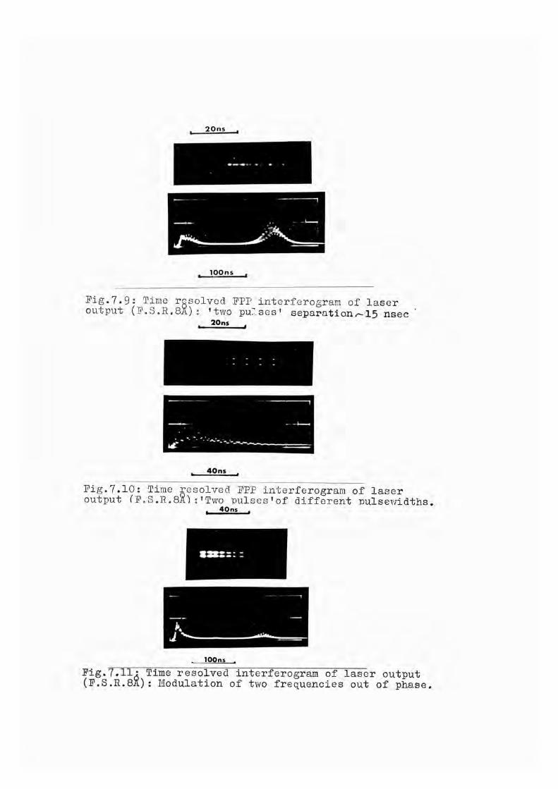
20ns
100ns
Fig.7.9: Time resolved FPP intorferogram of laser output (F.8.R.8X): ’two pulses' separationr-a5 nsec
20ns
40ns
Fig.7.10: Time resolved FPP interferogram of laser output fF.8.R.8X):'Two Dulses'of different mlsewidths
40ns
100ns
Fig.7.11 (F.8.R. Time resolved interferogram of laser output
: Modulation of two frequencies out of phase.

parent loss in officicncy of sun froquoncy generation rola- tiyo to second harmonic generation encountered, in the optical nixing cxporinent (Chapter 8).
Thus, by moans of high speed spectroscopic techniques, it has been established that, on the majority of occasions, the two frequencies were simultaneous vhLthin the single gianx pulse. Further evidence for this is implied later on in Chapter 8 when the two frequency output is used to generate the sum frequency in a non-linear optical crystal.
7.4: Two Frequency Output of the Laser System, Q-SwitchedWith a Saturable Absorber.In an attempt to study further the effects of the multi-
node character of the laser emission on the sum frequency and the second harmonic generation processes in ALP, as will be described in Chapter 8, the laser systexi was Q-spoiled with a bleachablc dye solution. The dye used v/as a solution of cryptocyanine in methyl alcohol.
A small cell of this solution, placed in the optical resonator of a laser, strongly absorbs light of the ruby wavelength, this absorption preventing nett amplification of light occurring until a high degree of population inversion has been attained. The pumping energy input increases until amplification in the ruby overcomes the loss due to absorp--
-135-

tien in the coll, and coherent light ’bleaches’ the solution which then becomes almost perfectly transparent to the ruby light. At this instant, there is a sudden large nett amplification, and a giant pulse containing all the stored energy is emitted.
As has been noted earlier, (Chapter 6.1.) due to its inherent gain and loss discrimination, the saturable filter also acts as a node selector, only allowing a few modes to build up to high power. The self beats of these nodes lead to output intensity fluctuations. Under certain conditions, this self-mode locking behaviour results in the output consisting of a train of pulses, of halfwidth 1 - 2 nsec, separated by the inverse of the resonator axial node frequency spacing (174). The length of the train of pulses is typically 30 - 50 nsec and the halfv/idth of the individual pulses depends on the number of axial modes present.
Similar results have been recorded by Q-spoiling the gain switched laser system, oscillating at two frequencies, with a cryptocyanine dye solution. The rotating prism was fixed in the optimally aligned position and a small 1,5 cm thick Brewster angle faced cell of cryptocyanine in methanol inserted in the optical resonator between the 6” ruby and the adjacent end mirror. The concentration of the cryptocyanine dye was adjusted until the laser gave single pulse
— 136—
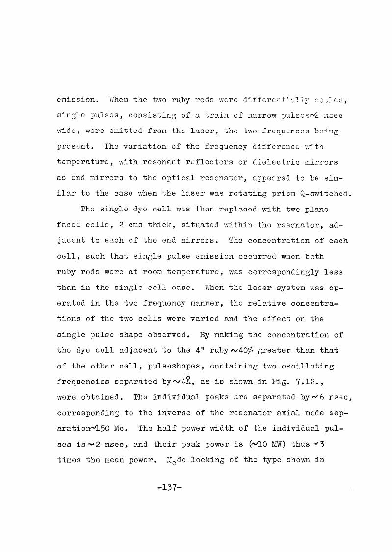
emission. \'/hen the two ruby rods were different:! ally cooled, single pulses, consisting of a train of narrow pulscs'^2 ncec wide, wore omitted from the laser, the two frequences being present. The variation of the frequency difference with temperature, with resonant reflectors or dielectric mirrors as end mirrors to the optical resonator, appeared to be similar to the case when the laser was rotating prism Q-switched.
The single dye cell was then replaced with two plane faced cells, 2 cms thick, situated within the resonator, adjacent to each of the end mirrors. The concentration of each cell, such that single pulse emission occurred when both ruby rods were at room temperature, was correspondingly less than in the single cell case. V/hen the laser system v/as operated in the two frequency manner, the relative concentrations of the two cells were varied and the effect on the single pulse shape observed. By making the concentration of the dye cell adjacent to the 4" rubyrv40^ greater than that of the other cell, pulseshapes, containing two oscillating frequencies separated by~*4%, as is shown in Fig. 7.12., were obtained. The individual peaks are separated by^^ô nsec, corresponding to the inverse of the resonator axial mode sep- aration'^50 Me. The half power width of the individual pulses is- 2 nsec, and their peak power is (^10 M ) thus "3 times the mean power, M^de locking of the type shown in
-137-

Pig.7.12 ; PulsGshape of the output of the laser system Q-switch^l with a saturable absorber: lOnsec/div.
(a)
(b)
Pig.7.13; Pulseshape of the output of the laser system Q-switched with a saturable absorber; lOOnsec/div*a) Fundamental beam 6943%.b) Second harmonic beam: (3472%) generated in ADP.

Fig. 7.12. did not occur in every laser shot when two frequencies were present. Occasionally pulses wore obtained which were^lO^ nodulated at'•'-'75 Me, half the axial node separation. This apparent randormess in the results was probably due to insufficient sensitivity in adjusting the operating parameters of the laser to create reproduolbility fmom shot to shot.
-•139-

CHAPTER 8: OPTICAL SUM CEIIERATION OP THE TWO FREQUENCY OUTPUT OF THE L/.SER.
8.0: Advantages of the Prosent System.One of the principal reasons for devising a laser sys
tem possessing the facility of a two frequency, single pulse output, was its suitability to the study of non-linear optical phenomena. The investigation of such effects as optical mixing in plasmas and anisotropic crystals may be considerably assisted vrith a laser of this type.
In this chapter is described an experiment which demonstrates the laser system’s capabilities in the non-linear optics field. The two tunable output frequencies of the lovser in a single giant pulse, the attainment of which is described in the previous chapter, were optically mixed in a crystal of ADP, resulting in the generation of the sum frequency (50). Spectroscopic and spatially integrated pulsa- shape measurements were made on the two fundamental frequencies and also on the output frequencies in the U.V. from the crystal.
This method of sum frequency generation possesses several distinct advantages over previous experiments. Since the laser power was 10 - 15 MU, and the conversion efficiency of the crystal was 15 , the output power at the mixed
.14 0_-

frequency was sufficient to enable a spectroscopic record with a single laser pulse. Previous experiments with solid state lasers employing photographic spectral detection utilized crystals possessing lov/cr generating efficiencies and required integration over a number of laser shots to achieve sufficient response. Except for those cases reported in which stimulated Raman lines are optically mixed with the fundamental, all other sum frequency generation experiments with the exception of Ref. (100), have used two separate sources.
In the present case, however, both frequencies, the spectral separation and relative intensities of ivhich may be varied, arc genora.tcd in a single resonant cavity, and are thus inlierently colinear, synchronous, and spatially coherent.
8.1 : Previous Experiments.The mixing of coherent or incoherent light beams in a
peizoeloctric material to produce the sum frequency is a wellknovm. non-linear optical effect.
In the first reported generation of the sum frequency, Bass ot al (26) utilized the wavelength variation of the R^ fluorescence lino with temperature, employing two separate relaxation oscillation ruby lasers operating at 77°K and

300°K. The two beams wore colincarizecl with a half silvered mirror and focused onto a crystal of try glycine suH.phate ; the two second harmonic beams and the mixed bean being photographically detected by means of a prism spectrograph. Since the tivo beams were of low power, nine successive laser shots were required for a spoctrographic record.
Using similar techniques Miller and Savage (l70) mixed the output frequencies from a ruby laser (6934%) and a CaV/0. : Nd " laser (1.1582 ) in a variety of crystals, including ADP and KDP. With both these experiments, the two beams had to be very precisely aligned and focused onto the same spot on the crystal.
Sum generation in ADP has also been achieved using two He. Ue. 0\i gas lasers oscillating at 1.1532yx.and 0.6328^.>t(12). The conversion efficiency was'' 10”^^ and the output powder of the mixed frequency was found to be proportional to the powers of the input beams.
The mixing of the small incoherent light output of the green line from a Dercury discharge lamp v/ith the output of a ruby laser has been reported (208). Sum frequencies have also been produced using purely incoherent light by mixing the different spectral lines of a xenon arc in ADP (145,146).
The observation of many spectral lines in the emission of solid state lasers in which Raman active liquids are sit
_142_

uated cither inside or outside the resonant cavity has been attributed to optical mixing of the Stokes and antiStokes free ■’oncics with the fundamental (73,244,162,150). In some cases, however, third order processes may be involved.
Recently, the sum generation in KDP of the frequencies of a ruby laser and a I'ld ” glass laser, originating from a single Q-switched resonant cavity was reported (100). Although the degree of synchronization of the two frequencies v/as not specifically mentioned, a sum generation conversion efficiency of ' l u was obtained,
8.2: The Experimental Arrangement.A schematic diagram of the experimental sot up for
the generation and detection of the sum of the two frequencies in the output pulse of the laser, when operated as described in Chapter 7, is shown in Eig. 8.1. A photograph of the experimental arrangement is shown in Eig.8.2,
The output from one end mirror of the laser system was incident on a 5 cm long crystal of ADP (supplied by SRDE, Christchurch, Hants) oriented in the phase matched position, The laser was operated in a manner such that the output contained tvm frequencies separated by •*■'4%. The second harmonic beams and the mixed beam generated in the crystal were incident on an aluminium coated Eabry-Perot interferometer
-143-

I D
O
O
k P — I Dp s
LL
co
-o-
\ /
oH <û:LÜ<U
EO)4-1CD>»CDLG)CDJ2G)
S*CG)
G)
O>4^G)
O%S.G)CG)‘ODE3CD75o
oo‘OD

+3 IT \
-r^ÏÏ^ÿ
V

m

(FPP) with a frcG spectral ran^o 4% (reflectivity 85fo, surface flatness of plates \/4-Cat 347oX). To disperse theUV 1:: ight sufficiently before incidence on the FPP, a short focal length Ions (f-5 on) and a ground quartz screen was inserted in the beau. Photographic record of the Fabry- Perot fringes was nade on Polaroid type 57, (3000 ASA) sheet film or on Kodak 'Royal X' spectroscopic film. A neutral density wedge (îTDO.O, hPO.3, ITP0.5, ÎTP0.8) wa,s placed in the focal plane of the caoera.
The pulseshape and relative power of the UY light was obtained by sampling the exit bean from the crystal with a glass plate, detection being with an RCA 1P28 (S5 photocathode) photomultiplier with suitable neutral density attenuation, and a Tektronix 585 oscilloscope. The latter was triggered by a pulse from an ITT photodiode which received a sample of the fundamental bean. Sufficient discrimination against the red light transmitted by the crystal was obtained with 3 cms of CuSC^nolar solution and Wratten 18A filters placed immediately in front of the camera and photomultiplier.
Simultaneous spectroscopic recording of the separation of the two fundamental frequencies v/as achieved by gaining a sample of the output from the other end mirror of the laser system with a pellicle, and making it incident on a ground
-146—

glass screen and a dielectric coated FPP (reflectivity'v98^, surface flatness [100 at 694oS) of free spectral range
Polaroid type 413 Infra Rod filn was used to record the fringes. A Wratten 70 filter was placed in front of the camera to eliminate non-laser light from the interferogran. The remainder of the beam was used for energy measurement with the calibrated thermopile. The spatially integrated pulse shape of the fundamental input beam was monitored with an ITT photodiode - Tektronix 519 detection system.
Thus for each single laser shot, the spectral character-, pulSGshape and energy, of the input and emergent beams from the crystal wore uniquely determined,
8.3: Second Harmonic Generation; Phase Matching.As has been mentioned in Chcpber 3, by balancing the
birefringence of the ALP crystal with its dispersion, a large increase in second harmonic generation is obtained.This is done by orienting the optic axis of the crystal at angle 6.-,;bo the dircctioh of propagation such that the fundamental beam, travelling as an ordinary ray has the same phase velocity as the generated harmonic beam travelling as an extraordinary ray. For ALP the value of 51^, obtained from substituting the relevant refractive indices (247)..' "=1-52 a,,^=1.50
-147-

into equation.' (3 - 7).Tho 5 COS thick crystal used in the experiment was cut
at 51^ with flat polished entrance and exit faces, and mounted with the plane containing the optic axis in the vertical plane on a goniometer assembly with vernier rotational and translational adjustment in both vertical and horizontal directions. The front face of the crystal v/as aligned to the ruby laser beam with the aid of the gas laser, to within' 10 minutes of arc. The crystal position was finally optimized by rotating it in the vertical plane by small increments~5 minutes until the second harmonic output detected by the photomultiplier was maximised. The measured conversion efficiency v/as between 0.1^ and Vfo, agreeing tolerably well with the theoretical estimate made from equation (3-12),
In order to ensure that the signal received by the photomultiplier was in fact that of the second harmonic, several different checks were made. A rod Wratten 70 filter which has a cut-off at 0.65/uwas placed in front of the photomultiplier with the result that no signal was recorded. V/hen this was replaced with a Polaroid filter oriented with the polarization axis in the horizontal plane there was a reduction in the signal, since the plane of polarization of the second harmonic is orthogonal to that of the fundamental
.-14.3—

(in this casG horizontal). Finally, the second harmonic was observed visually by placing a (P31) fluorescent screen, whic is insensitive to light at 70C01Î, In the beam.
By photographing this image an approximate value of A . 3 nilliradians was obtained for the bean divergence at the second harmonic. As expected this is less than the beam divergence of the fundamental which was' 6 nilliradians
An interesting result was recorded while the apparatus was being adjusted for Q-switcbing vlth one saturable absorber dye coll. In the process of optimising the concentration of the latter, the result shown in Fig.7.13 was obtained. The top oscilloscope trace shows the output of the laser at G943&; two pulses of approximately the same mean power are evident, the first being relatively unmodulated while the second exhibits strong mode locking. The lower oscilloscope trace, that of the photomultiplier record of the second harmonic, shows that the efficiency of SHG- was clearly greater for the mode locked pulse than for the previous unmodulated pulse. This agrees qualitatively with the work of Kohn and Pantell (130) who showed that there was an enhancement in the efficiency of second harmonic generation for mode locked laser pulses.
-149-

8.4: Sun Frequency Generation.This chapter describes the results obtained when the
outp V of the laser which v/as operated in such a manner as to give a two frequency output with a separation of 4% was optically nixed in ADP. Variation of the temperature difference of the two rubies produced a variation in the frequency separation and the relative intensities of the two lines could be varied by altering the pumping conditions.
A typical result for a single laser shot is shown in Fig. 8.3. Fig. 8.3(b) shows the interferogran of the fundamental beam; two lines separated b y 4.0%, and of slightly different intensities, arc apparent. The corresponding interferogran of the UV light shown in Fig. 8.3(a) confirms the existence of three lines, each separated by^/1.0&. The lines of maximum and minimum intensities are the second harmonics of the two fundamental frequencies, and the intermediate line is that of the mixed frequency. It will be noted that its intensity is between that of the other two lines. The intensity difference of the fundamental frequencies is exaggerated in the harmonics because of the nonlinear process. The UV fringes are much broader due to the low finesse of the interferometer (< 15) resulting from the use of aluminium coatings (high absorption) on FPP plates of nominal surface flatness ofA/ij-qat 347o2. Figs. 8.3(c) and
-150-

(a) (b)Pig.8.3: PPP interferograras of (a) mixed and (b) fundamental frequencies.
(c)
(d)
Pig.8.3 ; vuiiewpunuing puisesnapes or |,cj fundamental (20nsec/div) and (d) ultraviolet beams (50nsec/div),

8.3(d) shows the oscilloscope traces of the fundamental (20 nsoc/cra) and the UV light pulse (50 nsoc/cm) respectively.The power of the fundamental was 'v 10 Î/TU.
Many laser shots wore recorded with the laser working in this mode of operation. In all cases in which the two fundamental frequencies were simultaneous in one laser pulse, then the corresponding UV interferogram showed the existence of three equispaced lines, the intensity of the centre line, that of the mixed frequency, always being approximately midway between the intensities of the two second harmonic lines. This was also the case when the fundamental input beam was focused with an f - 50 cms lens into the ALP crystal.
However, when the same measurements were made with the laser being Q-switched with one, or two saturable absorber dye cells, although the two second harmonic frequencies were clearly in evidence, there was a total absence of any radiation at the mixed frequency. The explanation of this result is at present unclear. The effect appeared to be independent of whether the spatially integrated pulseshape was mode locked or not. Vdien the input beam was focused into the crystal, there w^s no change in the result, indicating that the explanation of the effect is not purely dependent on any spatial characteristics of the beam.
-152-

8.5: Comparison of Intensities.Similar results to those described in Chapter 8.4, ob
tained when the laser system was rotating prism Q-switched, were recorded on Kodak ’Royal X ’ spectroscopic film, in order that the UY interferograms could be densitometered. The relative intensities of the three lines T(2w, ), T(c W 2 ) and I (Cj, ) could then be compared.
It was shov/n in Chapter 5.4., that simple theory predicts the efficiency of sun frequency generation is four times greater than that of SHG for single node fundamental electric fields containing two frequencies. However, this type of field does not accurately represent the actual field distribution in the emission of a Q-switched ruby laser. This field distribution is difficult to delineate, due to the presence of more than one mode in the radiation.As has already been seen (l30), the relative phases between these nodes can affect the efficiency of SHG. Furthermore, Ducuing and Blocnbcrgcn (81) have shown that when two laser beams of different frequencies each containing Ndifferent nodes with random phases, arc mixed in a non-linear medium, there is a factor of (2 - H~^) improvement in SHG compared to sum frequency generation, which does not exist in the case of single node fields at two frequencies. This would mean that overall^sun generation would be only twice as efficient

as SHG. However, it is questionable whether the assumption of phase randomness is valid for the case of the present laser system.
Experimentally, it was found that the ratio^ of the intensity of sum frequency generation to the root of the I.)roduct of the two SH intensities,
was consistently less than this factor 2, and varied between the values 0.8 and 1.2 with a maximum error of -0.2. Ho improvement was noticed when the fundamental beam was focused into the crystal, indicating that the difference is not due purely to an effect associated with the spatial distribution of the bean. The discrepancy may well arise as a result of the peculiar node structure of the emission. From the time resolved interforometry ' of the two frequency emission of the system, a lack of complete synchronisation of the two frequencies within the single pulse was evident. The reason for the null sum frequency generation obtained when the laser was passively Q-spoiled, may have a similar explanation.
-154-

CHAPTER 9 : PTJRTHER APPLICATION OP THE LASER SYSTEM.
9.0: Possible Fields in Which the Laser May Have Application, It is evident from the recent published work referred
to in Chapter 1,8. that the field of research and development of high power pulsed lasers has reached a stage where
the design and construction of more complicated laser systems, to meet complek specific tasks, is now possible. The laser system described ih this report could well be included under such a classification.
The system’s unusual features of providing two, synchronised, parallel pulses, of the same power, or of variable relative powers, together with the facility of that each pulse may contain a spectral output consisting of two frequencies separated by up to 5.5&, may well have applications in many laser dependent fields of research.
It’s suitability to the study of non-linear optical phenomena has already been demonstrated. Further exploitation of the laser’s capabilities in this field may be envisaged. The possibilities of tunable frequency mixing in various materials may provide a useful method of probing molecular structure. The generation of millimeter waves by optical mixing is considered in the following chapter. The laser’s application to plasma diagnostics has already been
.155-

outlined and is briefly considred in Chapter 9,2.There nay well be further applications of the laser
system in other branches of laser physics, such as spectroscopy,laser induced plasma production,and holography. Those, however, will become apparent in the future.
9.1: The Generation of Millimetre Waves as a. DifferenceFrequency.— III mm mm "W
By optically nixing the two frequencies in the output of the laser system in a suitable media, it should be possible to detect the difference frequency, which will have a wavelength in the range 1 - 1 0 nn. This would be of considerable interest to the microwave engineer, who at the present time, has few coherent sources available to him in this spectral region.
The theoretical aspects of the generation and detection of waves in the far infrared and microwave regions has been considered by a number of workers (88,95,225). The successful generation of the difference frequency in other regions of the spectrum has been reported. The generation of 10 cm, waves by suitably mixing laser axial modes in crystalline quartz v/as reported by Hiebuhr (l83) while axial modes have also been mixed with phototubes (l47). Far infrared waves, in the 0.1 mm region have been generated in quartz by mixing
-156-

two frequencies from a neodymium gla.ss laser (248). The crystal was oriented in the phase matched position and a refrigerated gallium doped geri.ianium photoconductor used as a detector. number of difference frequencies in the infrared have also been generated by optically nixing various Raman lines (l63), but those are all of much shorter wavelength than considered here.
At the present time an attempt is being made to generate and detect the difference frequency of the tv/o frequency output of the laser in crystalline quartz. The quartz crystal, with polished input and exit faces is outside the laser resonator in the approximate phase matched position, in a similar manner to the sum frequency generation experiment. A choice of detectors is available.
9,2: Use of the Laser System for the Generation and Detectionof Resonant Plasma Oscillations.From previous discussion on the possibility of detecting
enhanced longitudinal electron oscillations in a plasma, produced by optical mixing, (Chapters 1.8. and 3.5.), it was apparent that the principle obstacle to the achievement of such a result was the simultaneous generation of two laser giant pulses oscillating at different frequencies (45). With the development of the laser system described in this thesis.
-157-

this obstacle has been removed.However, before the laser system could be employed
successfully, in such an experiment, some improvements, mostly of a technological nature, would have to be made.The most important of these is the necessity to increase the brightness of the laser. This may be facilitated, in principle, by (a) the addition' to the system of amplifier rubie; differentially refrigerated in lika manner to the oscillator rods, and optically isolated from the latter by a suitable absorbant dye, and (b) the improvement of the beam divergence specification of the system. Higher values of the frequency difference of the two oscillation frequencies could be achieved by technological improvement of the cooling system.
If the laser wa.s incorporated in an experiment with such a plasma as referred to in Chapter 3.5., a pulsed hydrogen arc, then a possible experimental arrangement as shov/n in Fig.9.1., might be adopted. The two beams from the laser would be focused at the correct angle into the plasma, by long focal length lenses, with the employment of suitable baffles, angular filters, etc., to reduce background light. For the plasma considered the coherently scattered light from each incident laser beam will consist of two beams scattered at an angle of «^4.6^ in the plane of the two incoming beams. One of these scattered beams will be buried
-158-
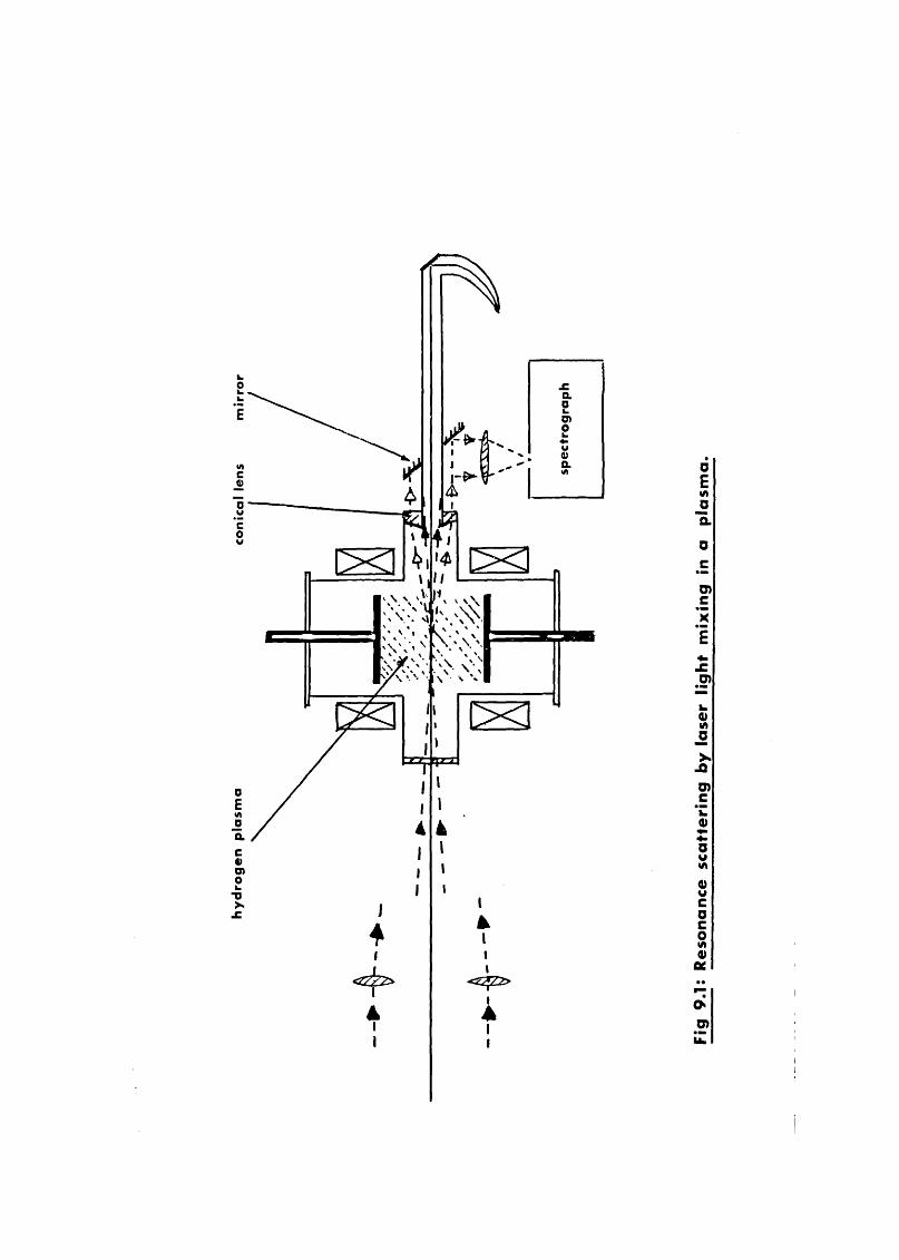
o XE
«ncQ>OVCow
\\s \
0EW)OQ.C0)D)O•aXX
0Etna"5.a
O)'xÊO)
s_oiD)ZooV«A0)wCOCOU)0)tt
D>
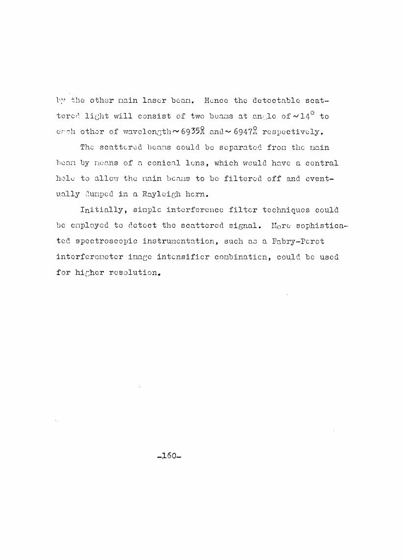
thû other nain laser bean. Hence the detectable scattered li ;ht will consist of two beans at o.n.' .lc of 14° to each other of wavolon^thr^ 69352 and^ 6947% respectively.
The scattered beans could be separated fron the nain bean by noans of a conical lens, v/hich would have a central hole to allow the nain beans to bo filtered off and eventually dunpcd in a Rayleigh horn.
Initially, simple interference filter techniques could bo employed to detect the scattered signal. More sophisticated spectroscopic instrumentation, such as a Pabry-Perot interferometer image intensifier combination, could bo used for higher resolution.
- 160-

COKCLTJS IQ H S
Tho work described in this thesis, as is common today of much research in tlie new .and frontier sciences, spans several branches of physics and technology. These encompass old and well-ustablished fields, such as interference spectroscopy, as well as the new an 1 rejuvenated sciences, atonii physics, plasma physics, and non-linear optics. Although many of the basic physical principles, upon which laser science is founded, were formulated many decades ago, v/ithout the benefits of the recent technological improvements made in crystal science, optical thin film techniques, sophisticated electronics and photoeloctronics, and a host of other disciplines, much, if not all, of the results herein described would have been unattainable.
Although the programme of research was orientated about a central theme, it was also initiated with a definite goal in mind. That is, the project was formulated within the context of a general spectroscopic analysis of the emission of giant pulse ruby lasers, and included efforts to reduce the spectral output of such to as narrow line- widths as possible. Concurrent with this general study, and ascribed equal importance, was the specific task of fabricating a Q-switched laser system possessing tho novel
_161_

features, here described. This was felt necessary as it was appreciated that the exciting new studios made on the interaction of light with matter, would be considerably assisted by the development of o. hi,'ii power laser system having a spectral output consisting of two frequencies,which were both tunable in separation and relative* intensity.Such a system has boon successfully constructed, and an extensive analysis of its spectral and temporal characteristics, including nanosecond time resolved spectroscopy, has been undertaken. The desirability of the application of this lasBr system to the study of non-linear optical phenomena has been verified by the successful generation of the sum frequency, and the direct comparison of the efficiency of this effect, with that of second harmonic generation (50).The possibility of utilizing" this laser in the observation of non-linear optical effects in plasmas resulted in a study into the feasability of producing and detecting enhanced longitudinal electron plasma oscillations within a hydrogen discharge of optimum parameters (45). From this, it was concluded that, with suitable improvements to the laser syster- such an effect should be detectable.
The general spectroscopic analysis of tho output of several different laser devices, including the ones herein described, was injected with considerable impetus by the
-162-

d0 lopnont of tho spherical Pabry-Pcrot interferometer; vTr.i.ch extended the range of realizable resolving powers attainable with conventional instruments, by over an order of viagnitude. With the aid of this powerful device it was possible to examine in detail the axial and off-axial node structure of giant pulses (47,49). Past tine resolved high resolution spectroscopy of the output of the gain switched laser system revealed the presence of an intensity dpcndent frequency shift (48). The existence of such an effect in conventional laser systems constitutes a. limiting factor to the effective spectral brightness attainable from giant pulse ruby lasers. Prom this detailed spectroscopic analysis, it became clear that the mode structure of giant pulse lasers cannot be satisfactorily deduced from photoelectric temporal detection of the intensity alone.
This experimental study may be considered to have contributed to the furtherance of laser science in several raspocts. A nov; laser system has boon developed for use in fields where simultaneous tunable two frequency emission is desirable# Additionally, the adoption of high resolution spectroscopic techniques has yielded elucidation cf much of the complex nature of the spectral output of p:iant pulse ruby lasers.
-165-

ACKNOWLEDGEMENTS
The author wishes to express his deep gratitude for the G .sotant guidance and encouragement of Professor D.J.Bradley, who supervised the project. He also acknowledges frequent h'jlp and advice from, and nuch stimulating discussion with Dr. C.Magyar.
The experimental work was carried out at the Culham Laboratory, UIvAEA, under an agreement between the latter and Royal Holloway College, The author wishes to thank those principally involved in this contract, Dr.R.Wilson and Mr. B.L. Tozer of Culbam Laboratory, and ProfessorS. Tolansky, and Dr. D.J.Bradley of Royal Holloway College, for the opportunity of benefiting from such cooperation.
The helpful advice and assistance of many members of staff at Culhaii and associates at Royal Holloway College,is greatly appreciated, especially that of Dr. T.J.M.Boyd,Dr. D.E.Evans, Dr. J. ICatzenstein, M.J. Eorrest, M.C.Engwell, and A.W. McCullough.
The author is deeply indebted to Mrs. Heather Richardson for invaluable assistance in the preparation of the manuscript.
-X64-

REFERENCES
1. ''Q\: ant urn Electronics” ed. C.H. Townes, Columbia E.F. New York (I960).
2, dvances in Quantum Electronics” ed. J.R.Singer, Columbia U.P., New York, (1961).
3. ”Proc. Symp. on Optical Masers Brooklyn”, ed. A.G.Fox,Polytechnic P., New York, (1965).
4. ”Quantum Electronics III” ed, P. Grivet, N. BloembergenColumbia U.P., New Y^rk (I964).
5. ”Quantum Electronics and Coherent Light”, Proc. Int.School of Physics. Enrico Fermi, Academic P.,New York (1963).
6. "Quantum Optics and Electronics” Les Houches, Gordon andBeach. New York (I964).
7. "Lasers I”, ed. A,K. Levine, Arnold, New York, (1966).8. ”Phys. Quan. Electronics” Conf. Proc, Puerto Rico., eds.
P.L.Kelley, B.Lax, P.E.Tannenwald, McGraw Hill, New York (1966).
9. R.L. Aagard, J.Appl.Phys. ^4, 3631 (1963).10.1.E. Abella, H.Z. Cummins. J.Appl.Phys. 32, 1177 (1961).11.1.E. Abella, C.H.Townes, Nature 1£2, 957 (1961).12.N.I. Adams, P.B. Schaefer. Proc.IEEE.51, 1366 (1963).13.H.G. Adamson, T.P. Hughes, E.M. Young. Quantum Electronics
III, Columbia. U.P. New York, p.1459 (l964).14.S.A. Akhmanov, A.I. Kovrigin, A.S. Piskarskas,
R.V, Khokhlov, Soviet Phys. JETP Letts, _2, 141 (1965).15.F.T. Arecchi, G, Potenza, A.Sona. Nouvo Cimento. 34,
1458 (1964).16.J.A. Armstrong, N.Bloembergon, J.Eucuing, P.S. Pershan,
P%ys. Rev. 127, I9I8 (1962).17.U. Ascoli Bartolli, G. Benedetti Michelangeli,L.Lovisetto.
Appl. Phys. Lett. 8, 332 (1966).-165- •

18. J.A. Baker, C.W. Peters. Appl. Opt. 1, 674 (1962).19. Ct.M. Barchubarov, G.S. Voronov, V.M, Gorbunkov,
N.B. Belono, Soviet Phys. JETP. 49, 386 (1965).20. b.R. Barone. J. Appl. Phys. , 831 (1963).21. S.R. Barone. T.R.G. Inc. Tech. Note 66 Bept. 2 (1963)
Referred to in ref. (223),22. N.G. Basov, A.M. Prokhorov. Ppoc. Acad of Sci. (USSR).
101> 47 (1945).23. N.G. Basov, A.M. Prokhorov. Soviet Phys, JETP. 27,
431 (1954),24. N.G. Basov, O.N. Krohlcin. Soviet Phys, JETP. 12, 1240
(I960).25. N.G. Basov, V.S. Zriev, P.G. Kryunkov* Appl. Opt. 1,
254 (1962).26. M. Bass, P.A. Erankon, A.E. Hill, O.W. Peters,
G. Weinreich, Phys. Rev. Lett. 8, 18 (1962).27. G. Baym, R.W. Hellwarth.Proc. IEEE QEI 3.09 (1965).28. R.C. Benson, M.R. Mirarchi. IEEE Trans Milt Electronics
8, 13 (1964).29. B.A. Berkley, G.G. Wolga. Phys. Rev. Lett. _9, 479 (1962).30. J.M. Birch. Proc. Quantum Electronics III. p.1187 (1964),31. N. Bloembergen, P.S. Pershan. Phys. Rev, 128, 606 (1962).32. N. Bloembergen. Proc. IEEE. 51, 124 (1963),33. N. Bloembergen, Y.R. Shen. Phys. Rev. 133A 37 (1964),34. N. Bloembergen. Proc. Int. Sch. on Quantum Optics and
Electronics. Les Houches. Publ. Gordon and Beach, p. 409 (1964),
35. N. Bloembergen. Proc. Int. Sch. Physics Enrico EermiCourse XXXI. Publ. Academy p. 247 (1964).
36. N. Bloembergen "Nonlinear Optics”, Publ . Benjamin.$^,York.(1965).
37. B.B. Boiko, N.S. Petrov, V.V. Valiiavko, I.M.Vashkevitch21. Prikl. Spektr. 3, 234 (1965),
-166—

33. LI. Born, E. Wolf, «’Principles of Optics’, Chapt. Vil. Pergamon, Oxford (i965).
39. G.B. Boyd, P.P. Gordon. Bell Syst, Tech. J. 40, 489(1961).
40. G.D. Boyd, H. Kogelnick. Boll Syst. Tech. J. 41, 1347(1962).
41. G.D, Boyd, R.G. Collins, S.P.S. Porto, A. Yariv, W.A.Hargreaves. Phys. Rev. Lett. 8, 269 (1962).
42. T.J.M. Boyd. Paper presented at IP and PS Conf. onScatt. and Nonlinear Optics. York, U.K, (1966).
43. D.J. Bradley, A.W. De Silva, D.E. Evans, M. J.Ecsrest,Nature. 199, 1281 (1963).
44. D.J. Bradley, B.Bates, C.O.L. Juulman, S, Majumdar.Appl. Opt. 3, 1461 (1964).
43.D.J. Bradley, G.Magyar, M.G.Riphardson. Proc. VII Int.Conf. Ion. Phen. in gases, Belgrade,Vol IIIp.199 (1965).
46. D.J.Bradley, Sciences et Ind. Spatiales 7/8 47- (1966).47. D.J, Bradley, M.S. Engwell, A.W. McCullough, G.Magyar,
M. 0. Richardson. Appl. Phys. Lett 2. T50 (l966).48. D.J. Bradley, G. Magyar, M.C. Richardson. Nature. 23^,
63 (1966).49. D.J. Bradley, M.S. Engwell, G.Magyar, A.W.McCullough,
M. C. Richardson (to be published),50. D.J. Bradley, G. Magyar, M. C. Richardson,(to be
published).51. D.J. Bradley(to be published),52. D.J. Bradley, C. Mitchell, (to be published).53. G. Bret, P.Gires. Appl. Phys, Lett. 4, 175 (1964).54. G. Burnbaum. "Optical Masers" Academic P,, New York
(1964).55. M. Burnbaum, T.L. Stocker. J. Appl. Phys. 531 (1966).56. G. Burns, M.I. Nathan. J. Appl. Phys. 34,> 703 (1963).57. E.A, Butayeva, V.A. Pabrikant. "Investigation on Expt,
& Th, Physics. A memorial to G.8. Landsberg" USSRAcad. So. Publ., Moscow (1959).
-167-

5G. J, A. CalviGllo, E.W. Eislicr and E.H. Heller.Proc.IEEE QEI 132 (1965).
5'j. H. Chabbal. Rev. d’Optique 21^ 49 (l958).' H. Cheng, Y.C. Lee. Phys. Rev. Lett. lA, 426 (l965).61. I.M. Ciftan, G.E. Lucl:, C.C. Schafer, H.Statz. Proc.
IRE 49, 960 (1961).62. M. Ciftan, A. Krutchkoff, S.ICoozekanani. Proc. IRE. 50,
84 (1962). —63. R.A. Clay, D. Eindlay. Phys. Lott. 19, 212 (l965).64. R.J. Collins, D.E. Nelson, A.L. Schawlow, W. Bond,
C.G.B. Garrett, W. Kaiser. Phys. Rev. Lott, g,303 (i960).
65. R.J. Collins, P. Kisluik. J. Appl. Phys. 33, 2009_(l962).66. S.A. Collins, G.R.White, Appl* Opt. 2, 448 (l963).
also Proc. Quantum Electronics III pl29 (l964).67. G.G. Comisar. Phys. Eluids 9,, 1037 (l966). Also paper
presented at APS Meeting Plasmas. San Erancisco(1965).
68. P. Connes. Rev. d'Optique 3^, 37 (1956).69. P. Connes. J. de Phys, et do Rad. ID. 262 (1958).70. J. H, Culhoni, R.W. Waynant. Appl, Opt. 3,989 (l964).71. E.K. Damon. Microwaves, p. 40 July (1964).72. V. Daneu, C.A. Sacchi, 0. Svelte, Proc. IEEE QE2 290(1966).73. L. W. Davies, S.L. McCall, A.P. Rodgers. J. Appl. Phys.
35, 2289 (1964).74. A.J. De Maria, R. Gagosz, G. Barnard. J, Appl, Phys.
34, 453 (1963).75. A.W. DeSilva, D.E. Evans, M.J. Eorrest. Nature, 203,
1321 (1964).76. I. D ’Haenens, O.K. Asawa. J. Appl. Phys. 33, 3201(1962).77. R.H, Dicko. U.S. Patent 2.851, 652. (Sept 9 1958).
-168-
/■'G. M. lidoLicnicoq R.H. Pantoll, 0. Svelto, J.H„ Weaver,Appl. Phys. Lott. 77 (1962).
-V ' P.P. Lu Hois, V. Gilinsky. Phys. Rev. 135, A995 (l964).:0. L.P. Lu Bois, Phys.Rov. Lett. 818 (1965),81. J. Ducuing, H. Bloembergen. Phys. Rev. 3^, A1493 (l964)82. R.C. Eckhardt, J.H. Bradford, J.W.Tucker. N'RL report
6444 (1966). Also Appl. Phys. Lett. 98, 285 (1966).83. A, Einstein. Phys. Zeit. 18, 121 (1917).84. V. Evtuhov, J.H. Hceland, Appl. Opt. 1, 517 (1962).85. V. Evtuhov, J.Ho Hceland. Quantum Electronics III
New Y^rk. p.1405. (1964),86. V. Evtuhov, J.H. Hceland. Ppoc. IEEE. ^ 1 . 7, (1965).87. V.A. Pabrickant. Doctoral Thesis. Phys. Inst. PV
Lebedev, Accd of Sci (USSR)(1939) quoted in ref. (57).
88. J. R. Eontana, R.H. Pantell. Proc. IRE _50, 1796 (1962).89. R, Eork, D.R. Harriott, H. Kogelnik. Appl. Opt. 3,
1471 (1964).90. A.G. Eox, T. Li. Bell Syst, Tech. J. 40, 453 (1961),91. P. A. Eranken, A.E. Hill, C.W. Peters, G.Weinreich.
Phys. Rev. Lott. 118, (l96l).92. P. A. Eranken, J.E. Ward. Rev. Mod. Phj^o. 33, 23 (1963)-93. L. M. Erantz. Appl. Opt. 3, 417 (1964). .94. M. D. Galanin, A.M. Leontovioh, Z.A. Chizhikova.
Soviet Phys,. JETP 16, 249 (l963).95. Cm. P. Gandhi. Proc. IRE 1829 (1962).96. G. Gehrer, D. Rbss. Zt. für Haturf. 2^,705 (1965)97. J E. Geusic, H.E.D. Scovil. Quantum Electronics III
p. 1219. Columbia U.P. How York (1964).98. K. S. Gibson. Phys. Rev. 8, 38 (1916).99. J. A. Giordmaine. Phys. Rev. Lett. 8, 19 (l962).
— 169—
100. Yu. A. Gol’din, V.G. Dmitriev, V.E. Tarasov, i'AW.Shkurov. Soviet PhYS. JETP Lett. 4, 297 (1966).
101. J. P. Gordon, H.Z. Zciger, C.H. Townes. Phys. Rev.25^ 282 (1954).
102. J. P. Gordon, H. Z. Zeigcr, C.H. Tournes. Phys. R^v.9a, 1264 (1955).
105. D.W. Gregg, S.J. Thomas. J. Appl. Phys. 37, 3750 (1966). —104. Yu M. Gryaznov, O.jj. Lebedev, A.A. Chastov. Opt.
and Spoct. 20, 278 (l966).105. R.H. Hall, ©.E. Pcnncr, J. D. K-ngsley, T.J. Soltys,
R.O. Carlson. Phys. Rq v . Lett. 9, 366 (1962).106. G.R. Hanes, B.P. S-toicheff. Nature .^5, 587 (i962).107. 0. S. Heavens "Optical Masers". Methuen, London
(1964).108. J. L. Helfrich. J, Appl. Phys. _34, 1000 (l963) .109. R.W. Hellwarth. "Adv. in Quantum Electronics"
Columbia U.P.,New York p. 334 (l96l).110. R.W. Hellwarth. Hughes R s. Lab. Report Nq . 300
(1964).111.M. Herchcr. Appl. Phys. Lett. 7, 39 (l965),112. D.R. Harriott. Appl. Opt. 2, 865 (1963).113. W.R. Hook, R.H. Donnington, R.P. Hilberg. Appl.
Phys. Lott. 9, 125 (1966).114. T.P. Hughes. Nature 195, 325 (1962).115. T.P. Hughes, IC.M. Young. Nature 1^, 332 (1962).116. D.A. Jackson, Proc. Roy. Soc. 2^, 289 (i960).117. P. Jacquinot. Reports on Progress in Physics.XXIII
267 (I960).118. A. Javan, W.R. Bennett, D.R. Harriott. Phys. Rev.
Lett. 6, 106 (1961).119. A. Javan, E.A. Ballick, W.L. Bond. J. Opt. Soc. Am.
52, 96 (1962).—17 0—
/
120. A. Javan, P.L.Kelley. Proc. IEEE QE2 XXXIX (i9 6 0 )Abstract only, and Proc. IEEE C)E_2 470 (1966).
121. E.A. Jenkins, H.E. lliite. "Fundamentals of Optics! Chapt.14. McGraw Hill, Hew Y^rk (1957).
122. I.E. Johnson, K. Nassau. Proc. IRE _49, 1704 (1961).123. R. Kafalas, J.I. Masters, E.Murray, J. Appl. Phys, 35,
2349 (1964).124. Y/.H. Kegel. Proc. VI Int. Conf. on Ion.Phen. in Gases.
Paris p. 189 (1963).125. W.H. Kegel. Zt. fûr Naturf. 20a, 793 (1965), also Inst
itut fhr Plasmaphysik Reports IPP/6/9 (l963) andIPP/6/21 (1964).
126. D.A. Kleinman, P.P. Kisliuk. Dell Syst. Tech. J« 41,453 (1962).
127. D.A. Kleinman. Phys.Rev. 125, 87 (1962).128. D.A. Kleinman, Phys.Rev. 1£6, 1977 (1962).129. D.A. Kleinman. Phys.Rev. 1E8, 1761 (1963).130. R.L, Kohn, R.H. Pantell. Appl. Phys. Lett. 8, 231 (1966)131. V.V. Korobkin, A.M. Leontovioh, M.V. Popova. Soviet
Phys. JETP Lett. 3, 194 (1966).132. N.M. Kroll, A.Ron, N. Rostoker. Phys.Rev.Lett.3D, 83
(1964).133. N.M. Kroll. Physics of Quantum Electronics p. 86.
McGraw Hill. New York (l966),134. P.P. Kupper, E. Eunfer. Phys.Lett. 3D, 486 (1965).135. P.P. Kupper. Physica ^2, 1825 (l966).136. B.A. Lengyei ,"Lasers". Wiley, New York (1962).137. B.A. Longyel, ion. J. Phys. 903 (1966).138. B.A. Longyel, "Introduction to Laser Physics" Wiley,
New York (1966).139. P.J. MeClung, R.W. Hellwarth. J. Appl. J.Appl. Phys.
33,828 (1961).
-171- /

140. P.Jo McClung, R.W. Hcllwarth. Appl, Opt. Supplement,1. p. 103 (1962).
141. P.J. McGlung, R.W. Hcllwarth, Proc. IEEE. 51, 46 (1963).142. x.J. McGlung, D. Weiner. Proc. IEEE. C^, 94 (l965).143. D.E. McGumhcr, M,E. Sturge. J. Appl. Phys. 34, 1682
(1963).144. B.B. McEarland, R.H. Hoskins, B.H. Softer. Hature. 207,
1180 (1965).145. B.H. McMahon, A.R. Franklin. J. Appl. Phys. 36, 20y3
(1965).146. B.H. McMahon, A.R. Franklin. J. Appl. Phys. 36, 2807
(1965).147. B.J. McMurtry, A.E. Siegman. Appl. Opt. 1, 51 (1962).148. B.J. McMurtry. Appl. Opt. £, 767 (l963).149. F. Mace, G. McGall. Proc. IEEE 53, 74 (i965).150. R. Madhavan, M.K. Bheer, T.S. Jaseja. Appl. Ont.
1823 (1966).151. G. Magyar. Rev. Sci. Inst, 38, 517 (1967).152. T.H. Maiman. Brit. Commun. Elect. 7, 674 (i960) .153. T.H. Maiman. Hature. 1^, 493 (i960).154. T.H. Maiman. Phys. Rev. Lett. 4, 564 (i960) .155. T.H. Maiman, R.H, Hoskins, I.J.B'Hoancns, O.K. Asawa,
V. Evtuhov. Phys. Rev. 123, 1151 (1961).156. T.H. Maiman, Phys. Rev. 123, 1145 (l961).157. K. Maischberger. Inst. fUr PlasmaPhysik, Garchin,
Report. IPP 4/34 (l966,*158. P. B. Maker, R.W. Terhune, M. Hisenhoff, C.M. Savage,
Phys. Rev. Lott. 8, 21, (1962).•159. S.M. Mameladzo, Opt. and Spcct. _20, 96 (l966).160. H. Manger, H. Rother. Phys. Lett. 7, 330 (1963).
—172—

161. H. Manger. Zt.für Ang. Phys. 1^, 265 (l965).162. B'I.D. Martin, E.L. Thomas, J.K. Wright. Phys. Lett. 15,
136 (1965).163. M.D. Martin, E.L. Thomas. Proc. IEEE QE2, I96 (1966).164. J. Martinolli. J. Appl. Phys. T?, 1939 (1966).165. J.I. Masters, hature. .19 , 442 (1963).166. J.I. Masters, J. V/ard, E. Hartouni. Rev. Sci. Inst.
34, 365 (1963).167. J.I. Masters, hature. 202, 1092 (1964).168. M. Menât. J. Appl. Phys. _3 , 73 (l965)-169. J.E. Midwinter. Brit. J, Appl. Phys. IB, 1125 (l965).170. R.C. Miller, A. Savage. Phys. Rev. 128, 2175 (1962).171. R.C. Miller, B.A. Kleinman, A. Savage. Phys. Rev. Lett.
11, 146 (1963).172. R.W. Minck, R.W. Terhunc, C.C. Wang, Proc. IEEE, 54,
1357, (1966).173. D.V. M^ssio, K.h. Socher. Alta Ercquenza. XXXIV 323,
(1965).174. H.W. Mocker, R.J. Collins. Appl. Phys. Lett. 7, 270
(1965).176. B. Montgomery. Physica 31, 693 (l965).177. M.I. hathan, W.P. Bumke, G. Burns, P.H. Bill, G.Lasher,
Appl. Phys. Lett. 1, 62 (1962).178. H.C. hedderman, Y.C. Kiang, E.L. Unterlcitner. Proc.
IRE 1686 (1962).179. B.E. Nelson, R.J. Collins, J. Appl. Phys. 32, 739(1961)180. B.E. Nelson, R.J. Collins, "Adv. in Quantum Electron
ics" p.79 Columbia U.P. New York (l96l).181. B.E. Nelson, M.B.Sturge. Phys. Rev. 137, 1117 (l965).182. Nguyen van Tran, B, Kehl. Appl. Opt. 5, 168 (1966).
-173-

183. K.E. Niebuhr. Appl. Phys. Lett. Z, 106 (i965).184. H. Opov/er, W. Kaiser. Phys. Lett. 21, 638 (1966).185. E.R. Pcressini. Appl. Phys. Lett. 3., 203 (1963).186. P. S. Pershan, "Progress in Optics"ed. E. Wolf.
North Holland, New York. p. 85 (1966).187. P. M. Piatzman, B.J. Buchsbaum, N. Tzoar, Phys. Rev.
Lott. 12, 573 (1964).188. P.M. Piatzman, N. Tzoar. Phys. Rev. 1_36, All (1964).189. R. Poratesi, G.T. Li Erancia, L. Ronchi. Nuovo
Cimento. 3j!;, 40 (1964).190. A.M. Prokhorov. Soviet Physics. JETP. ^4, 1658 (l958).191. T.M. Quist, R.H. Redikcr, R.J. Keyes, W.E. Krag,
B. Lax, A.L. McWhorter, H.J.Zeiger. Appl. Phys. Lott. 1, 91 (1962).
192. D.A. Reago, E.L. Green, M. Schoenfeld. Eall Meetingof Opt. 80c. Am. (1963).
193. D. RÜSS. Appl. Opt. 3, 259 (1964).194. L. ROss. Proc. IEEE 196 (1964).195. L. RÜSS. "Laser Lichtverst&rkor und Oszillatoren"
A.V.G. Erankfort (i966).196. A. Salat. Zt. für Naturf. 20a, 689 (1965).197. A. Salat. Phys, Lett. 15, 139 (l965).198. A. Salat. A. SchlRtcr. Zt. für Naturf. 20a,460 (1965).199. K. Sauer, G. Wallis. Proc. Vllth Int. Conf. on Ion.
Phen, in Gases. Belgrade. Vol. Ill, 453 (1965).200. A. Savage, R.O. Miller. Appl. Opt, 1, 661 (1962).201. G, Schaack. Zt. für Angew. Phys. 385 (l964).202. A.L. Schawlow, C.H. Townes. Phys. Rev. 112, 1940(1958)203. A.L. Shawlow, G.E. Levlin. Phys. Rov. Lett. 6, 96
(1961) .
-174-

204. A.L. Schawlow, G-.E. Lovlin. reported in P.P.Kisluik, W.8, Boyle. Proc. IRE 49, 1635 (1961).
205. K. Shiraoda, P.O. Wang, C.H. Tov/nes. Phys. Rev. 102,1502 (1956).
206. I. P. Shkarofsky, R.C.A. Victor. Report.?. -801-53(l966).
207. S. Singh, R.C. Smith, M.Lidomenico. Proc. IEEE 53,507,(1965).
208. A.W. Smith, H. Braslau. IBM J. Res. Lev. 6, 361(1962)209. P. W. Smith. Appl. Opt. 4 1038 (1965).210. W.V. Smith, P.P. Sorokin "The Laser'.’ McCraw Hpll,
Hew Y^rk. (1966).211. E. Snitzcr. Phys. R^v. Lett. 7, 444 (l961).212. E. Snitzcr. J. Opt. Soc. Am. 51, 491 (l96l).213. E. Snitzer. Appl, Opt. _5, 121 (I966).214. V. Sochor, K. Homial. Czech, J, of. Phys, Bl$ 578
(1966).215. B.H, Softer. J. Appl, Phys. _35, 2551 (l964).216. W.R. Sooy, R.S. Conglcton, B.E. Lohraz, W.K.Hg.
Quantum Electronics III. p. 1103. Columbian.P. Hew York. (1964).
217. W. Sooy. Appl. Phys. Lett. 7, 36 (1965).218. P.P. Sorokin, M,J, Stevenson, Phys. Rev. Lott. _5.
557 (i960).219. P.P. Sorokin, J.J, Luzzi, J.R, Laakard, G.L.Pettit,
IBM J. Res. Lev. 8, 182 (1964).220. L. Spitzer Jr. "Physics of Eully Ionized Gases"
Interscience. How York (1962).221. R.A. Stern. Phys. Rev. Lett. 1_4, 538 (1965).222. R.A, Stern, H. Tzoar, Phys. Rov. Lett, ]^, 785 (l966)223. C.M. Stickley. Appl. Opt. 3, 967 (l964),
-175- y

224. G.W. Stroke. Progress in Optics, ed. E.Wolf. Vol. II p.3. Berth Holland,Hew York (l062).
225. Mo Takatsuji. Jap. J, Appl. Phys. 5., 389 (l966).226. H.VM Terhune, Ford Motor Co. Report (1963).227. S. Tolansky "High Resolution Spectroscopy".
Methuen, London, (1946).228. S. Tolansky, "Multiple Beam Interferometry
of Surfaces and Films". Chap. XV Oxford U.P, (l948).
229. S. Tolansky, B.J. Bradley, Symposium onInterferometry n. 375 HMSO, London,(1959).
230. C.H. Tomes. Private communication (1951)footnote to Alsop et al, Phys. Rev. 107, 1450 (1957).
231. G. Troup "Masers and Lasers", Methuen, London(1963).
232. J. Ch. Vienot, A. Orsag, J. Pasteur, R.Saron,J. Bulahois. Appl. Opt. 5, 1003 (I966).
233. A.A. Vuylstekc. J. Appl. Phys. 1615(1963).
234. W.G. \7agncr, B.A. Lengycl. J. Appl. Phys,34 2040 (1963).
235. C.C. Wang. Proc. IEEE 51,1767 (1963).236. C.C. Wang, G.W, Racettcr. J. Appl. Phys. 36,
3281 (1965).237. J. F. Ward. Rev. Mod. Phys. 37, 1, (1965).238. R.W, Phynant, J.H. Cullom, I.T, Basil,
G.L. Balwin. Appl. Opt. 4, 1648 (1965).239. J. Weber, Trans IRE. Prof, Grp. on Electron
Devices. P.G. E.D., 3, (1953).240. I. Wiedor, L, R. Sarles. Phys, Rcv, Lott. 6,
95 (l961).
—17 6—

241. I.H. Wlnor. Appl. Opt. 5, 1437 (1966).242. J. P. Wittlcc. J. Appl. Phys. 33, 2333 (1963). .43. J.K. Wright. Contomp. P^ys. 6, 1 (1954).244. T. Yajima, M. Talcatsuji. J. Phys. Soo. Jap.
19, 2343 (1964).245. A. Yariv, Proc. IEEE. 51, 1723 (1963).246. A. Yariv, J.P. Gordon. Proc. IEEE _5_1, 4 (1963).247. P. Zoriiiokc. Jnr. J. Opt. Soc. Am. 54, 1215
(1964). —248. P. Zcriiiko Jnr., P.P. Berman. Phys. Rcv. lott.
15, 999 (1965).
-177-

TH E CO-OPERATIVE SCATTERING OF LASER LIGHT IN A THETATRON PLASMA 199
The ratio between the Thomson and the Rayleigh cross-sections is
A*» y 2m / c** 4 71 (n — 1)2 ’
where N is the number density of molecules, n the index of refraction of the gas at one atmosphere pressure, and A the wavelength of the laser light. Taking nitrogen as the Rayleigh scattering medium gives the result
o'c/crN2 = 3.65 X 10^
and this indicates that electrons at a number density of 5 X 1016 cm "2 scattering incoherently ( a < l ) will scatter as much light as 0.7 atmospheres of nitrogen. The total light scattered co-operatively ( a > l ) is a half of this and so corresponds to 265 torr of nitrogen. The stray light, which is 92 Torr of nitrogen, should therefore contribute only about one quarter of the observed signal due to the co-operative feature when the latter is not spectrally resolved. However, it is proposed to use a Fabry-Perot étalon with a plate spacing of 1.5 mm giving an inter order spacing of1.5 Â to resolve the ion feature. It is expected that a finesse o f 20 can be achieved, and a multichannel device which divides the interferometer fringe system into 20 equal parts has accordingly been built, making use of an axicon mirror system described by Katzen- stein /5 / and illustrated in Fig. 3. The KORAD laser line width is narrower than 0.07 Â and could consequently be confined to one channel of an instrument of infinite contrast. Integrating the Airy formula for the instrumental fringe shape shows in fact that rather less than half of the light from a monochromatic line illuminates resolution intervals
other than the one in which the line appears to be. central. The accompanying table shows the stray light position which can be expected with this instrument. Each channel is one resolution interval; the laser line is assumed to lie entirely within channel 0. Light intensities are expressed in terms of the pressure in Torr of nitrogen which would give rise to the same signal by Rayleigh scattering.
TABLE 1
Channel Number 0 1 11 111
Stray light Plasma signal Total signal Plasma/total
51.5 15.066.5 22.5%
14.5 15.029.5 51%
3.915.018.979%
1.615.016.690%
It is proposed in the first instance to make a search for the peaks at the plasma frequency by merely tilting a narrow band interference filter in front of a single photomutliplier. A more sophisticated approach, consisting of an array of interference filters whose pass bands are spaced out over a range of approximately 100 A, will later be used to locate these peaks in a single shot.
REFERENCES
1. A. W. DeSilva, D. E. Evans and M. J. Forrest, Nature 203, 1321 (1964).
2. U. Ascoli-Bartoli, J. Katzenstein and L. Loviesetto, Nature 207, 63 (1965).
3. E. E. Salpeter, Phys. Rev. 120, 1528 (1960).4. T. V. George, L. Slama, M. Yokoyama and L. Goldstein,
Phys. Rev. Letts. 11, 403 (1963).5. J. Katzenstein, J. Appl. Optics 4, 263 (1965).
RESONANCE SCATTERING DUE TO LASER LIGHT MIXING IN A PLASMA
. D. J. BRADLEY, G. MAGYAR and M. C. RICHARDSON
UKAEA Culham Laboratory and Royal Holloway College, University o f London, U.K
1. IntroductionThe mixing of two laser beams in a crystal to
produce a third light beam of the sum or difference frequency is now a well-known phenomenon. More recently, the generation of coherent hypersonic waves with laser beams by non-linear electrostrictive coupling in dielectrics, including liquids, and detection of the light subsequently scattered by the acoustic waves, has been reported. A third phenomenon is the non-linear mixing of two laser beams in a plasma to produce longitudinal electron plasma waves which
then scatter the remaining laser light. This resonant excitation of longitudinal plasma oscillations by non-linear mixing of two laser beams was first studied by Kroll, Ron and Rostoker / I / , as a possible plasma density probe by detection of the scattered light from the exciting beams or alternatively from a third laser beam. As with light mixing experiments in crystals this is an effect essentially depending upon coherence. While in the case of crystal mixing the well organized crystalline structure permits large scale volume effects over a range of sum and difference

2 0 0 D . J. BRADLEY. G, MAGYAR and M. C. RICHARDSON
frequencies, in plasma the coherence volume and density are both much smaller and it is only when the difference frequency approaches the plasma fiequency that generation of plasma waves occurs. Further, electron plasma waves are limited in amplitude by collisional and Landau damping or by the effects of convective non-linearities on the plasma excitation, so that the generation and detection of these resonant plasma oscillations will be correspondingly more difficult.
The relative advantages of two beam and three beam probes have been further discussed theoretically /2 / and the various assumptions of reference / I / including the small perturbation assumption have been evaluated and shown to be valid for low temperature plasmas /3,4/.
In order that non-linear resonance should occur with two laser beams E,, E; of frequencies coi, 0J2 and wave vectors k,, it is necessary that the following experimental conditions be achieved /I, 4/(a) coi—co2=cop-\-Aco; Aco<^cop and
COj CÜ2>C0j,cop = (4n n/my/^ the electron plasma frequency.
(b) k, —k2=k-f-Ak, A k < k , | kj — k 2 1 Ld< 1for collective excitation; L d = (KT/47t ny/^
the Debye length.(c) coi,2 > k i,2 • V, c o ^ k v i h l Vih is the thermal
electron velocity.(d) (Ej • E 2 /rcoM must not be so large as to make
ÀjtetP 'ijk of the same order as E\, E 2 ', E is the Landau or collisional damping whichever is larger, (k, co) is the resonant density fluctuation.
Condition (c) is necessary so that the cold electron plasma equations can be employed and condition (d) ensures that the non-linear resonance longitudinal field will not be of the same order as the transverse fields and thus make the original perturbation assumption invalid. Practically, this will be true for low temperature plasmas /4/.
The scattering cross-section is then proportional
to A:2(Ei .E2)2(5[k-(k,-k2)]/«cui"<L2/>|£(k,cu)P, (2) where e (k, co) is the longitudinal dielectric constant given by
I e (k, co) |2 = (1 — (coplco)2)2 + E2. (2)From (2) it can be seen that detuning of the
resonance will be caused by non-uniformity in density, and hence in plasma frequency or by any dissipation in the plasma. Thus the choice of a suitable plasma is rather limited.
Thompson scattering and Stark broadening measurements on a pulsed hydrogen arc in this laboratory have given an electron density of 9 X 10^4 cm~^ and an electron temperature k T =2 .2 eV.
If the angle between two laser beams is chosen to make kLo = 0.27 i. e. an angle of 4.6°, then the
Landau damping is / I = 3.3 x 10“ ^ and the collision damping is Fc = 2.3 X 10“I
If detuning due to density variations is to be of the same order as dissipative effects then ônjn < 3 X 10“ over the scattering volume of 10“ cm^ (say). With these conditions the ratio of scattered to incident energy is 5 X 10“ ’ for Ei, £ 2 = 10 V cm~L These calculations, of course, imply that the laser spectral width is narrow enough to allow AcopjoDpr^
1.5 X 10“ i. e. '^O.OôÂ and that the laser power output is large enough to produce a field of 10? V cm~h
The experimental conditions for this plasma seem less critical particularly with respect to uniformity of plasma density and spectral purity of the laser beams than for the plasma of Ref. /I / , without any reduction in the ratio of scattered to incident energy for a given laser power density.
Normally spectral width and peak power of laser giant pulses are inversely proportional and although the power density could be increased by performing the scattering inside the laser cavity the most serious obstacle to experimentally demonstrating resonant excitation of plasma oscillations with light beams would appear to be the production of synchronised laser beams of sufficient spectral purity and adequate power. However, measurement of the scattered flux for the above plasma and laser light fields should be possible /5 / and we wish to propose a suitable laser system, and to describe initial results obtained in evaluating its performance.
Finally, a proposed detection system is briefly discussed.
2. A Two-Beam, Two Frequency Giant Pulse Ruby Laser
The idea of using two separate lasers of different frequencies had to be rejected for two reasons. First of all, since even the best-controlled Kerr-cell switched lasers have 5— 10 nanosec jitter, complete synchronisation would not be possible so that the two independent pulses would only partially overlap. Secondly, the theory assumes that the two mixing light beams are of the same width and have the same polarisation and mode-structure. These conditions are more easily obtained if they are generated in the same cavity.
Kerr-cell switching introduces Raman scattered lines, which can substantially broaden the laser output spectrum. While cooling would eliminate this, one of the lasers has to be at room temperature to permit generation of two frequencies separated by cop. Passive Q-switching devices are ruled out because of uncertainty in timing. Q-switching by a rotating prism was chosen . This method employs the minimum number of components in the cavity. This helps to achieve the required high spectral purity and also reduces losses, thus maximizing output power. .

RESONANCE SCATTERING DU E TO LASER LIGHT M IXING IN A PLASMA 2 0 1
A schematic diagram of the laser is shown in Fig. 1. It is basically a gain switching device. The two ruby rods are pumped optically in two separate ellypticai cylinder cavities in the socalled “exfocal” configuration i. e. ruby and matching linear flashtube are situated symmetrically on the major axis of the
F-P2Fig. 1. Two beam, two frequency (7-swifched ruby laser. RP: rotating prism, Rr. cooled ruby, Rz: ruby, C: Nitrogen gas
cooling. F-P 1 and 2: Fabry-Perot étalon reflectors.
ellipse, between the foci and the end point. When maximum inversion is reached, the rotating prism is timed to turn into the coupling position. Then both rubies suddenly find themselves in a common Fabry- ■Perot cavity, the light describes figure of eight path while travelling between the end-mirrors. A giant pulse of laser light results and population inversion drops below threshold level.
The rotating prism and the ruby rod ends are Brewster angled to reduce super-radiant pre-lasing losses. At these high powers the use of any coatings — reflection or antireflection — is not practicable.
The end-mirrors are parallel plate resonators which give about 60% reflectivity — the optimum for this type of laser — by constructive interference. The various distances between the parallel surfaces are so chosen that the maximum reflectivity occurs only for a narrow frequency bandwidth. This facilitates axial mode selection. In fact, near threshold only a single axial mode is generated. The rubies were (Linde superior quality) both 3/8" in diameter, 3" and 5" long, respectively, 0.05% Cr^+ concentration, 90° orientation, with roughened sides to reduce losses due to spurious side-modes.
Parallel plate resonator reflectors also lead to more rapid ^-switching with a rotating prism with consequent decrease in pulse rise time and increased power output.
The laser when operated at room temperature, produces a single-beam, single-frequency output when one mirror is replaced by a prism or a TIR end ruby is employed. The cavity length is then doubled. When working under this regime the laser multipulses for prism speeds of up to 40000 rpm. Up to 6 regularly spaced (by 1/2 microsec) giant pulses have been obtained, of equal intensity (2—3 MW near threshold), of high spectral purity (< 0.01 Â). These
could be of interest for some applications and a detailed description will be published elsewhere.
For the proposed experiment the most important feature is the simultaneous g-switching of two differently tuned laser rods rather than the gain switching mechanism. The production by mixing of a resonant frequency which corresponds to 4.3 Â in terms of a wavelength shift is required. This can be conveniently achieved by keeping one ruby rod at room temperature and cooling the other to about — 52 °C. By further cooling the range could be extended to 9 Â. A moderate warming of the other rod could perhaps increase this range to about 12 A (although warming would tend to reduce the peak power available.) So neglecting other considerations the maximum plasma density for which this method would be available is Ke'~^8 X IQis.
The cooling of one laser rod is accomplished by blowing dry nitrogen gas into the pumping cavity, after passing it through a helical tube immersed in liquid air. The tuning is then achieved by simply regulating the flow of the gas. We are able to control the temperature of the ruby to about 1 °C down to the required temperature corresponding to rb 0.06 Â at 6939 A which is within the above theoretical requirement. To prevent the condensation of moisture on the Brewster-angle faces they are defrosted with a steady flow of dry hot air.
At this temperature difference the fluorescence lines are so much shifted that each ruby should act independently when they lase near their natural line peaks. However, the important point is that they should not act as absorbers either. The cooled ruby, of course, has higher gain, so a shorter rod is used for this half of the laser.
At the moment peak power is limited by losses in the rotating prism which has rather bad geometrical aberrations and inhomogeneities.
Spectral width measurements were obtained with a Fabry-Perot variable gap interferometer. The plates, flat and parallel A/120, were silvered to 90% reflectivity giving an instrumental finesse 25. ' The width of fringes photographed on polaroid film (type 57) appeared to be instrumental even at 5 cm plate separation. Simultaneous pictures of the output of a biplanar f a s t . photodiode on Tektronix 519 oscilloscope (combined bandwidth 1 Gc/s) showed beats modulating the pulse amplitude suggesting that the linewidth due to axial modes was narrower than indicated by the Fabry-Perot photographs.
3. Detection of Resonance Scattering
The experimental arrangement will basically be as is schematically shown in Fig. 2. The two outputs from the laser are first passed through separate evacuated angular filters, not shown on the diagram, and are focused into the plasma with the required angular separation of 4.6°. The plasma is generated between stainless steel electrodes, 50 cms apart in

2 0 2 D . J. BRADLEY, G. M AGYAR and M. C. RICHARDSON
Fig. 2. Resonance scattering by laser light mixing in a plasma. L ] / = 300cm lens. P, hydrogen arc plasma. A, conical lensM, mirror. Lj, lens. S, spectrograph.
200 mTorr of hydrogen and is maintained for about 350 microsec by means of an axial magnetic field of 5 kGauss /5/. For such a plasma it is reasonable to assume that the fractional variation in density Ô nin < 3 X 10“ over a distance of 1 m m for the duration of the laser pulse, typically 40 nseconds.
The coherently scattered light from each incident laser beam will consist of two beams scattered at an angle of 4.6° in the plane of the two incoming beams. One of these scattered beams will be buried by the other main laser beam. Hence the detectable scattered light will consist of two beams at an angle of 14° to each other, both of wavelengths 6934.1 and 6947.3 A.
The scattered beams will be separated from the main beams by means of a suitable conical lens, which will also serve as a plasma vessel end window. The conical lens has a central hole to allow the main
beams to be filtered off and eventually dumped in a Rayleigh horn.
Initially a narrow band interference filter will be employed to detect the scattered light signal. Later a Fabry-Perot interferometer image intensifier combination is contemplated.
We wish to acknowledge many useful discussions with Dr. J. M. Boyd, Dr. D. E. Evans, and Dr. J. Katzenstein.
REFERENCES
1. N. M. Kroll, A. Ron and N. Rostoker, Phys. Rev. Letters 13, 83 (1964).
2. A. Salat, Physics Letters 15, 139 (1965).3. H. Cheng and Y. C. Lee, Phys. Rev. Letters 14, 426 (1965).4. D. Montgomery, Physica 31, 693 (1965).5. A. W. DeSilva, D. E. Evans and M. J. Forrest, Nature
203, 1321 (1964).
FAR INFRARED FARADAY ROTATION IN A PLASMA
A. N. DELLIS, W. H. F. EARL, A. MALEIN and S. WARD
UK Atomic Energy Authority, Culham Laboratory, Abingdon, Berks, UK
Pulses of laser radiation, of wavelength 28 fi, have been transmitted through gas discharge plasrnas in the direction of a known superimposed magnetic field and the rotation of the plane of polarization measured. Rotations of up to 60° were observed. Values of the plasma electron density, calculated from these Faraday rotations, are compared with values measured simultaneously, using a laser interferometer working at 3.39 fx wavelength. Good agreement is found between the two estimates of density. The operation of the apparatus designed for measuring the Faraday rotation is discussed in detail.
1. Introduction
I shall describe measurements o f the Faraday rotation of a beam of radiation, of wavelength 28 (jl, in its passage through a laboratory plasma. The infrared source used, giving 1 ^sec pulses of peak power 10 W at this wavelength, is of the type described by Large and Hill /I / .
For a plasma of electron density n cm-^ having constant superimposed magnetic field B gauss parallel to the propagation path of length / cm, the Faraday rotation in radians is
y = 2.63 X 1 0 - " (1)where the wavelength A is in cm. Much greater rotations are therefore observed than in previous work using shorter wavelengths /2, 3/.

Reprinted from
Volume 9, Number 4 APPLIED PHYSICS LETTERS 15 August 1966
DIRECT SPECTROSCOPIC DETECTION OF RUBY LASER GIANT PULSE OFF-AXIAL MODE STRUCTURE
(rm temp; 10 MC linewidths; E)
Daniel J. Bradley, Malcolm S. Engwell, and A. W. McCulloughRoyal Holloway College
University of London Englefield Green, Surrey, England
George Magyar and Martin C. Richardson U.K.A.E.A., Culham Laboratory
Culham, Near Abingdon Berkshire, England
(Received 29 June 1966)
Single axial mode operation of giant pulse ruby lasers has been previously reported. *® While it has been claimed that the spectral bandwidth of one of these laser systems is limited by pulse duration (for the 1-cm-gap Fabry-Perot étalon employed, this would imply a recorded finesse of 250), for the other system the measured spectral linewidth was much greater than the corresponding spectral transform from the pulse width measurements. More recently a single off-axial confocal giant pulse laser system has been reported.^ In this case the evidence for
single transverse mode operation was based on the observation of pure far-field mode patterns.
We report the direct spectral detection of off- axial modes of giant pulse ruby lasers, including single off-axial mode output.^
To resolve with a plane Fabry-Perot interferometer (FPP), off-axial modes of a typical giant pulse ruby laser (GPRL) with a pulse width of 40 nsec and hence a spectral bandwidth of 25 Me, would require an étalon gap of some 20 cm for an instrumental finesse of 40. At this resolving power the
150

V olum e 9, Num ber 4 A P P L I E D P H Y S I C S L E T T E R S 15 August 1966
plane in te rfe ro m ete r is not very lum inous, so sam pling o f the laser rad ia tion is usually not possible and in terferogram s o f low pow er pulses cannot be pho tog raphed . T h e spherical Fabry-Perot in te rfero m eter (FPS), on the o th e r hand , is well suited fo r this kind o f high-resolution spectroscopy due to its high lum inosity’ with the added bonus that the plates are perm anently in ad justm ent.
T h e detection system arran g em en t is shown in Fig. 1. T em pora l m odulation o f the giant pulse o u tpu t was observed with a b ip lanar pho todiode and a T ek tron ix 519 oscilloscope o f com bined passband 1 Gc. Initially the main laser o u tp u t was sent into a “low reso lu tion” FPP to detect m odes, if any, o u tside the free spectral range o f 750 Me o f the FPS. O nce a rep roducib le narrow spectral ou tpu t was achieved, the FPP was replaced by a TR G calorim e te r fo r accurate m easurem ents o f o u tpu t power. T h e FPS was adjusted for m ultiple-beam m arginal- focus spherical aberra tion fringes, localized in the in te rfe rom ete r m erid ional plane.'^ T hese FPS fringes have a very nearly linear dispersion outside the central fringe, o f great advantage fo r laser d iagnostics.
Some results a re shown in Fig. 2. F igure 2(a) shows a typical spectrum o f a slow-switched (rota ting prism ) GPRL (3" X 3/6" ruby rod in an effective 200 cm cavity). M ode selection was accom plished with a 3-plate optically contacted resonant reflector. T h e FPS in te rfe rog ram (p ho tog raphed on K odak IF film IR 135) reveals off-axial m ode s tru c tu re in the two m ain com ponents which are them selves separated by five axial m ode spacings. At lower resolving pow er, particularly if Polaroid film was em ployed, these w ould ap p e a r as two single-axial m odes. T h e total spectral w idth o f ~ 200 Me o f each o f these com ponents greatly exceeds the 50 Me expected from the pulse du ra tio n transfo rm .
P H O T O - D I O D EG A S L A S E R
0C A M ER
R U B Y L A S E R V FA^BRY P E R O T( P L A N E )
F A B R Y P E R O T ^( S P H E R I C A L )
C A M E R A
Fig. 1. Arrangement for direct spectroscopic detection of giant pulse laser off-axial modes.
T his recorded spectral w idth is the same as the figure quoted by McGlung and W einer and the FPS in te rfe rog ram thus confirm s the ir hypothesis that spectral ou tpu t Ijroadening is in part due to the presence of several off-axial modes.
Figures 2(5) and 2(c) show ou tpu ts o f a fast- switched (PockcTs cell) GPRL (4 in. X 9/16 in. ruby rod in an effective f 00 cm cavity). M ode selection was achieved by em ploying a 2-plate resonant reflecto r liacked u |) with a cryptocyanine cell isolator. By pum ping very near th reshold , single off-axial mode ou tp u t was obtained (Fig. 2(5)). F igure 2(c) shows two off-axial m odes. T he two com ponents are spaced by 40 Me com pared with the axial m ode separation o f 150 Me. As would be expected from the pulse w idth o f 200 nsec (5 Me transform ), the spectral line width o f these single off-axial m odes was narrow enough to set an u p p e r limit o f 10 Me for the FPS instrum enta l w idth. For these GPRL systems, off-axial m ode spacings should exceed" this < 10 Mc/.s in strum enta l width.
Fig. 2(a). Spherical Fabry-Perot interferograms and corresponding oscilloscope traces o f mode-selected giant pulse ruby laser outputs. Free spectral range: 750 Me. Output spectrum of rotating prism giant pulse ruby laser. Time-scale: 20 nsec/cm. Peak power 1 mW.
151

Volume 9, Number 4 A P P L I E D P H Y S I C S L E T T E R S 15 August 1966
Fig. 2{b). Output spectrum o f a Pockels cell switched giant pulse ruby laser. Time scale: 100 nsec/cm. Peak power 100 kW.
Fig. 2(c). Same as (b), except two off-axial modes.
M ore generally we have fo und th a t fo r the sam e peak pow er fast sw itched g iant pulses a re spectrally “cleaner” than slow ones. I t is also in te resting to note that the oscilloscope traces do no t show any difference betw een single o r double off-axial m ode operation although the expected beat frequencies fall w ithin the detection bandw idth . In fact we have observed th a t th e re is little correla tion betw een beat patterns and FPS spectra; the la tte r usually contain m any m ore lines than w ould be expected from the pulse envelope pattern . Single-m ode opera tion cannot th e re fo re be safely in fe rred from the absence o f beats.
T h is w ork, first re p o rted at the Paris IC O 7 M eeting, (May, 1966) form s p art o f a general investigation o f the spectral purity o f laser giant pulses which will be described in detail in a fu tu re publication.^
‘ F. J. McGlung and D. Weiner, IEEE J. Quantujn Electronics, QE-1, 9 (1965).
-M. Hercher, Appl. Phys. Letters, 7, 39 (1965). V. Damos, C. A. Sacchi and C. Svelto, IEEE J . Quantum Elec
tronics, QE-2, 4 (LXVIII), 1966.^D. j . Bradley, M. Engwell, G. Magyar, A. W. McCullough and
M. C. Richardson, ICO 7 Meeting, Paris, 1966. (To be published). "P. Connes, Rev. Opt., 35, 37 (1956).«C. M. Stickley, Appl. Opt., 3, 967 (1964).
152

INTENSITY DEPENDENT FREQUENCY SHIFT IN RUBY LASER
GIANT PULSES
ByDr. D. J. BRADLEY, Dr. G. MAGYAR
andM. C. RICHARDSON
(Reprinted from Nature, Vol. 212, No. 5057, pp. 63-64, October 1, 1966)

(Reprinted from Nature, Vol. 212, No. 5057, pp. 63-64, October 1, 1966)
Intensity Dependent Frequency Shift in Ruby Laser Giant Pulses
I n th e course o f a general in v estig a tio n o f th e spectral o u tp u ts o f h igh ly m onochrom atic g ia n t pu lse ru b y lasers^ w e h a v e d e tected an in te n sity dep en d en t frequency sh ift.
The giant pulse ruby laser used was a ro tating prism, gain-switched type®, where the prism m om entarily couples two ruby rods (0 in. by 3/8 in. and 4 in. by 3/8 in.), exfocally pum ped by linear flash tubes, into a common resonator. B oth ou tpu t mirrors were three-plate optically contacted resonant reflectors of 56 per cent peak reflectiv ity .
A 10 cm spherical F ab ry -P ero t interferom eter, free spectral range 750 Mc/s, provided adequate spectral resolution of 10 Mc/s w ith the added advantages of higher luminosity® and stability of adjustm ent over a plane F ab ry -P ero t interferom eter. Time resolution was achieved by strealdng the fringes* w ith an S.T.L. image tube camera. A lthough the image tube had an antim ony-caesium »S11 photocathode, of very low quantum efficiency a t the ruby laser wavelength (6943 Â), because of the high luminosity of the spherical F ab ry -P ero t interferom eter i t was possible to record fringes a t a writing speed of 2 nsec/m m on 10,000 A.S.A. ‘Polaroid’ film, w ith a tim e resolution of 2 nsec.
The cam era was focused on th e meridional plane of the spherical F ab ry -P ero t interferom eter which was adjusted for m ultiple beam m arginal focus spherical aberration fringes, localized in th is plane®. A suitable slit was in te rposed in the diverging cone of interference fringes so as to restric t the rings for streaking norm ally to the slit length. Tem poral m odulation of the spatially integrated o u tpu t of the giant pulse was simultaneously recorded w ith a biplanar photodiode ‘Tektronix 519’ oscilloscope system w ith a combined band pass o f about 1 Gc/s.
Fig. 1 shows a typical result. The streak p icture and the m onitor pulse envelope trace are on the same tim e scale. As expected from elem entary theory* th e Interference fringes appear some 20 nsec after the beginning of the light pulse—this being the tim e required to estabhsh a finesse of about 15 in a spherical F ab ry -P ero t interferom eter o f 750 Mc/s free spectral range. The m ost conspicuous feature of the fringes is the shift tow ards increasing diam eter and thus increasing frequency. F or peak cavity powers of 5-10 MW the average shift is about 200 Mc/s and the average lifetime of such a shifted fringe is about 20 nsec. Sometimes a la ter fringe appears, and

40 nsec
Fig. 1. Streak pliotosraph of spherical Fabry-Perot interferogram and corresponding oscilloscope trace of laser giant pulse. Both time scales, 20 nsec/cm. Free spectral range, 760 ûlc/s. Peak output power, 5 MW.
20
18
16g
a 14
i 12
1 10iI 8O*g 6
4
2
I j
1 2 3 4 5 6 7 8 9 10 11Peak power (MW)
Fig. 2. Plot of rate of frequency shift against peak laser power.
this is of the same diameter as tha t a t which the original fringe started.
Time-dependent frequency shifts towards the red in

relaxation-oscillation ruby lasers have been previously reported®’®. A shift of 10 Mc/s per |rsoc® was accounted for by changes in the length and refractive index o f the ruby rod resulting from temperature effects. Our recorded shift o f 10 Mc/s per nsec is too rapid to be explained by thermal changes and, moreover, is in the direction of increasing frequency.
Fig. 2, which shows a plot o f the observed rate o f shift as a function of peak cavity power, indicates a linear relationship power dependent with a slope o f 1 4 Mc/s per nsec per MW. All tlie pulses measured had durations of about 35 nsec at the half-power level. Greater than average shifts usually occurred with more strongly (temporally) modulated giant pulses and vice versa. Taking into account the effect on peak power of such m odulation would lead to a reduction in the spread of the experim ental points. Local variations in power across the laser beam would also contribute to this spread. W hile such spatial variations are integrated by the photodiode, because the spherical Fabry-Perot interferometer, unlike the plane interferometer, is not translationally invariant
20 nsec
40nsecFig. 3. Streak photograph of laser light distribution in the plane of the interferometer. Streak times, 10 nsec/cm; resolution, 1 nsec. Pulse
time-scale, 20 nsec/cm. Peak output power, 5 MW.

in a parallel laser beam, each streaked fringe corresponds to a small local region of the cross-section of the laser beam.
This linear power relationship suggests th a t the frequency shift arises from a non-linear optical electric field effect. In order to explain the filam entary nature of the ou tpu t of Q-switched ruby lasers, Jav an and Kelley’ suggested th a t self-focusing in ruby crystals results from non-linear anomalous dispersion. Whereas self-trapping would require an increase in th e refractive index of the ruby, if the laser operates on the high-frequency side of the resontmce line a decrease in refractive index should result. The m agnitude of the required change in refractive index can be easily obtained from the equation
2 { n l r + D = (1)
for the wavelength X, corresponding to an axial mode of order m, of a plane parallel resonator consisting of a ruby rod of length h, and refractive index n, and an air p a th of length fg. D ifferentiation and rearrangem ent give the relationship
Sn = — [ { n l r + h)llr] [Sv/v] + (8m/21r)(c/v) (2)
Substituting our da ta (L = 25 cm, = 56 cm, and V = 4-3 X 10^* c/s) gives 8n = — 1-9 x 10 ® for Sv = -4- 200 Mc/s, which corresponds to a 5 MW outpu t pulse. (An estim ate of Sn of — 3 x 10~® for a Q-switched ruby laser operated a t room tem perature is given in ref. 6.) 8m = 0 for constant axial mode num ber m.
Finally, we took streak photographs of the laser beam cross-section as it appears in the plane of the spherical F ab ry -P ero t interferom eter. A slit selected a suitable portion of the beam (to include a few “filam ents” ), which was then streaked a t 1 nsec/mm. A typical photograph is shown in Fig. 3. The intensity was usually m odulated a t th e same ra te as the beats of the oscillogram. Also noticeable was the filam entary character of the emission and the random switching of the various filaments, some of which only lasted for a few nanoseconds.
These results help to in terpret some of the apparently contradictory features of spectra of giant pulse ruby lasers. Very sharp lines (about 10 Mc/s) and off-axial mode spacings of about 40 Mc/s were observed^ on some interferogram s when the laser was operated ju s t above threshold (approxim ately 100 K W output)—when a negligible spectral shift would be expected. A t higher powers, spherical F ab ry -P ero t interferograms showed fringes of which the w idths vary random ly around a ring, b u t w ith the twofold screw axial sym m etry expected w ith a spherical interferom eter’ . The broader fringe sections then corresponded to filaments operating a t high powers

and the narrow sections to low power filaments. W hen a plane spherical F ab ry -P ero t interferom eter was used in the parallel beam, the interferogram s of the giant pulse ruby laser were uniform ly broadened, as expected.
The frequency difference of approxim ately 150 Mc/s between the two sets of fringes shown in Fig. 1 corresponds to a change of Sm = 1 in equation (2). The resulting beats between these two axial modes were no t then affected by the continuous shift in frequency, which was the same for both components. This is confirmed by the oscillogram of Fig. 1.
An im portan t conclusion from these results is th a t nonlinear effects in the active m edium lim it the effective spectral brightness (power per un it frequency interval) obtainable from giant pulse ruby lasers.
After this work had been completed, a similar spectral shift in the ou tpu t of a passive Q-switched giant pulse ruby laser was reported®. Power dependence of the shift was no t considered, and the suggestion th a t laser heating could account for a decrease in the refractive index of the cryptocyanine and thus in the optical length of the cavity does no t apply to our ro tating prism giant pulse ruby laser.
Royal Holloway College, Englefield Green, Surrey.
D. J . B r a d l e y *
G. M a g y a r M . C. R i c h a r d s o n
U .K . Atomic Energy A uthority ,Culham Laboratory , >Culham, near Abingdon, Berkshire.
* Present address: Department o f Physics, Queen’s University of Belfast, Belfast.' Bradley, D. J., Engwell, M., Magyar, G., McCullough, A. W., and Richard
son, M. C. (to be published).* Bradley, D. J., Magyar, G., and Richardson, M. C., Proc. Eighth IrUem.
Conf. on Phenomena in Ionized Oases, Belgrade, August 1965 (in the press).
* Connes, P., Eev. d ’Optigue, 85, 37 (1956).* Bradley, D. J., Bates, B ., Juulman, C. 0. L., and Majumdar, S., A pp. Op., 3,
1461 (1964).• Hughes, T. P., Nature, 195, 325 (1962). '• Hanes, G. R ., and Stoicheff, B. P., Nature,19S, 587 (1962).’ Javan, A., and Kelley, P. L., I.E .E .E . J . Quant. Electron, 2, xxxix (1966).• Korobkin, V. V., Leontovich, A. M., and Popova,M. N., J .E .T .P . Letters, 3,
194 (1966).
Printed In Great Britain by Fisher, Knight Sc Co., Ltd., St. Albans.


![Introduction to Ruby [Εισαγωγή στην Ruby]](https://img.dokumen.tips/doc/110x75/558cd1aad8b42ac4438b46b4/introduction-to-ruby-ruby.jpg)


![Ruby on Rails [ Ruby On Rails.ppt ] - [Ruby-Doc.org: Documenting](https://img.dokumen.tips/doc/110x75/554f9e1eb4c9057b298b4732/ruby-on-rails-ruby-on-railsppt-ruby-docorg-documenting-.jpg)


![Ruby on Rails [ Ruby On Rails.ppt ] - [Ruby - [Ruby-Doc.org](https://img.dokumen.tips/doc/110x75/5491e450b479597e6a8b57d5/ruby-on-rails-ruby-on-railsppt-ruby-ruby-docorg-.jpg)

