Embed Size (px)
Citation preview
1
A Training Simulation System with Realistic Autonomous Ship Control
Monica Nicolescu, Ryan Leigh, Adam Olenderski, Lt. Ryan Aleson (Retd.)
Sushil Louis, Sergiu Dascalu, Ancient Paths Musement
Chris Miles, Juan Quiroz, [email protected]
University of Nevada, Reno
1664 N. Virginia St. MS 171
Reno, NV, 89523
monica|leigh|olenderski|sushil|
dascalus|miles|[email protected]
Abstract
In this paper we present a computational approach to developing effective training systems for virtual simulation
environments. In particular, we focus on a Naval simulation system, used for training of conning officers. The
currently existing training solutions require multiple expert personnel to control each vessel in a training scenario, or
are cumbersome to use by a single instructor. The inability of current technology to provide an automated mechanism
for competitive realistic boat behaviors thus compromises the goal of flexible, anytime, anywhere training. In this paper
we propose an approach that reduces the time and effort required for training of conning officers, by integrating novel
approaches to autonomous control within a simulation environment. Our solution is to develop intelligent, autonomous
controllers that drive the behavior of each boat. To increase the system’s efficiency we provide a mechanism for
creating such controllers, from the demonstration of a navigation expert, using a simple programming interface. In
addition, our approach deals with two significant and related challenges: the realism of behavior exhibited by the
automated boats and their real-time response to changes in the environment. In this paper, we describe the control
architecture we developed that enables the real-time response of boats and the repertoire of realistic behaviors we
designed for this application. We also present our approach for facilitating the automatic authoring of training scenarios
and we demonstrate the capabilities of our system with experimental results.
I. INTRODUCTION
Virtual simulation environments provide a good application area both for entertainment and for serious simulations
such as those used in training. In this paper, we focus on an application for training conning officers and we describe
our approach to creating a robust and effective training system. The goal of this training is to teach conning officers
how to drive big ships in the context of high-traffic, potentially dangerous situations. Developing an appropriate
training system poses significant challenges, which will be addressed in this paper.
A significant problem with current training solutions is the reduced efficiency of the systems, in terms of the
personnel required for running them, and thus their cost. Currently, a typical training scenario follows scripted
procedures, with pre-planned events, and are performed in low-density environments. The latter constraint is due
October 9, 2007 DRAFT
2
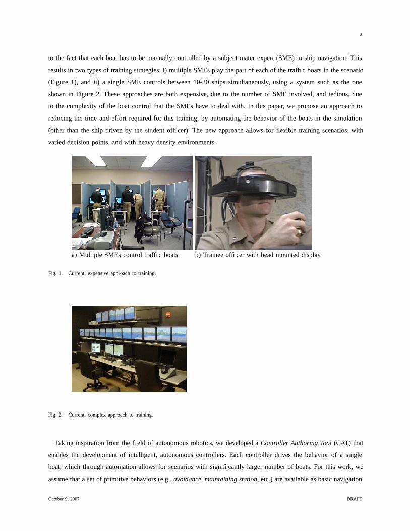
to the fact that each boat has to be manually controlled by a subject mater expert (SME) in ship navigation. This
results in two types of training strategies: i) multiple SMEs play the part of each of the traffic boats in the scenario
(Figure 1), and ii) a single SME controls between 10-20 ships simultaneously, using a system such as the one
shown in Figure 2. These approaches are both expensive, due to the number of SME involved, and tedious, due
to the complexity of the boat control that the SMEs have to deal with. In this paper, we propose an approach to
reducing the time and effort required for this training, by automating the behavior of the boats in the simulation
(other than the ship driven by the student officer). The new approach allows for flexible training scenarios, with
varied decision points, and with heavy density environments.
a) Multiple SMEs control traffic boats b) Trainee officer with head mounted display
Fig. 1. Current, expensive approach to training.
Fig. 2. Current, complex approach to training.
Taking inspiration from the field of autonomous robotics, we developed a Controller Authoring Tool (CAT) that
enables the development of intelligent, autonomous controllers. Each controller drives the behavior of a single
boat, which through automation allows for scenarios with significantly larger number of boats. For this work, we
assume that a set of primitive behaviors (e.g., avoidance, maintaining station, etc.) are available as basic navigation
October 9, 2007 DRAFT
3
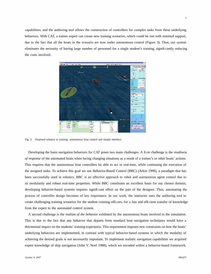
capabilities, and the authoring tool allows the construction of controllers for complex tasks from these underlying
behaviors. With CAT, a trainer expert can create new training scenarios, which could be run with minimal support,
due to the fact that all the boats in the scenario are now under autonomous control (Figure 3). Thus, our system
eliminates the necessity of having large number of personnel for a single student’s training, significantly reducing
the costs involved.
Fig. 3. Proposed solution to training: autonomous boat control and simple interface.
Developing the basis navigation behaviors for CAT poses two main challenges. A first challenge is the readiness
of response of the automated boats when facing changing situations as a result of a trainee’s or other boats’ actions.
This requires that the autonomous boat controllers be able to act in real-time, while continuing the execution of
the assigned tasks. To achieve this goal we use Behavior-Based Control (BBC) (Arkin 1998), a paradigm that has
been successfully used in robotics. BBC is an effective approach to robot and autonomous agent control due to
its modularity and robust real-time properties. While BBC constitutes an excellent basis for our chosen domain,
developing behavior-based systems requires significant effort on the part of the designer. Thus, automating the
process of controller design becomes of key importance. In our work, the instructor uses the authoring tool to
create challenging training scenarios for the student conning officers, for a fast and efficient transfer of knowledge
from the expert to the automated control system.
A second challenge is the realism of the behavior exhibited by the autonomous boats involved in the simulation.
This is due to the fact that any behavior that departs from standard boat navigation techniques would have a
detrimental impact on the students’ training experience. This requirement imposes new constraints on how the boats’
underlying behaviors are implemented, in contrast with typical behavior-based systems in which the modality of
achieving the desired goals is not necessarily important. To implement realistic navigation capabilities we acquired
expert knowledge of ship navigation (John V. Noel 1988), which we encoded within a behavior-based framework.
October 9, 2007 DRAFT

4
The implementation of the game engine and the graphics display are also main components of the entire system,
but they are outside the scope of this paper. The work presented here, a part of a larger scale project, focuses on
the aspects related to autonomous boat control.
The remainder of the paper is structured as follows: Section II describes related approaches to our work and
Section III describes our simulation environment. Section IV presents our behavior and controller representation and
Section V presents our behavior repertoire. Section VI describes the concept of controller triggers and Section VII
describes the details of our authoring approach. We present our experimental results in Section VIII and conclude
with a summary of the proposed approach in Section IX.
II. RELATED WORK
Simulation systems for training have received significant interest in recent years. Representative examples include
flight simulators (Tambe, Johnson, Jones, Koss, Laird, Rosenbloom & Schwamb 1995, van Lent & Laird 1999,
Pearson, Huffman, Willis, Laird & Jones 1993) and battlefield simulators (Calder, Smith, Courtemarche, Mar &
Ceranowicz 1993, Phongsak Prasithsangaree & Lewis 2004). In contrast with the above approaches, the system we
propose in this paper provides an authoring mechanism to facilitate the development of autonomous controllers for
the agents involved in the simulation. Our approach is inspired by the programming by demonstration or learning
from apprenticeship paradigm, in which systems learn from observing human expert behavior. This method has
been employed in a wide range of domains, such as intelligent software systems (Lieberman 2001a, Lieberman
2001b, Lieberman & Shearin 2001), VLSI design (Mitchel, Mahadevan & Steinberg 2005), physics (Shavlik 1985),
agent-based architectures (Angros 2000), and robotics (Schaal 1997, Dautenhahn & Nehaniv 2002, Abbeel & Ng
2005).
In the mobile robotics domain, which provided the inspiration for our system, successful approaches that rely
on learning from demonstration have shown learning of reactive policies (Hayes & Demiris 1994), trajectories
(Gaussier, Moga, Banquet & Quoy 1998), or high-level representations of sequential tasks (Nicolescu & Mataric
2003). These approaches employ a teacher following strategy, in which the robot learner follows a human or a robot
teacher. Our work is similar to that of (Aleotti, Caselli & Reggiani 2004, Onda, Suehiro & Kitagaki 2002, Ogata
& Takahashi 1994), who perform the demonstration in a simulated, virtual environment. Furthermore, our work
relates to teleoperation, a very direct approach for teaching by demonstration. Teleoperation can be performed using
data gloves (Voyles & Khosla 2001) or multiple DOFs trackballs (Kaiser & Dillmann 1996). These techniques
enable robots to learn motion trajectories (Delson & West 1996) or manipulation tasks (e.g., (Yang, Xu & Chen
1993)). Using such “lead-through” teaching approaches (Todd 1986) requires that the demonstration be performed
by a skilled teacher, as the performance of the teacher in demonstrating the task has a great influence on the
learned capabilities. Another difficulty that may arise in teleoperation is that the training may be performed through
instruments that are different than what the human operator would use in accomplishing the task. In addition, the
actual manipulation of the robot may influence the accuracy of the demonstration. Within the scope of this work,
we propose the use of an interface as a tool for learning new training scenarios from an expert’s demonstration.
October 9, 2007 DRAFT
5
This interface is significantly optimized from that currently used by the navy experts during their training exercises
and allows the transfer of expert knowledge through standard computer input devices.
III. SIMULATION ENVIRONMENT
For this work, we developed a 3D simulation environment, called Lagoon (Figure 3), which allows for simulating
a wide range of boats, from small cigarette boats to medium ships, such as sailboats, to large ships, such as destroyers
and aircraft carriers. All boats have realistic physics, which the controllers take into account when autonomously
driving the ships. Within this architecture, each boat can be controlled via the Authoring or the Execution panel
(Figure 3, right side of screen). When an entity is selected, the panel and its associated behaviors refer to that entity.
Whenever a new entity is selected, the behavior information for that new entity is displayed. The boats are equipped
with 7 primitive behaviors, each of which has an associated control panel (Section V): approach, maintain station,
ram, move to, avoid entity, avoid land and fire. The top level of the Authoring panel displays information about the
selected entity: name, current speed and course, desired speed and course, and position. The lower section displays
information about the target ship (when applicable - Section V): name, speed, heading, position, range and bearing
to target. The bottom section of the Authoring panel provides manual controls for actuating the selected entity, as
an alternative to behaviors.
IV. BEHAVIOR-BASED CONTROL ARCHITECTURE
Behavior-based control (BBC) (Arkin 1998) has become one of the most popular approaches to embedded
system control both in research and in practical applications. Behavior-based systems (BBS) employ a collection of
concurrently executing processes, which take input from the sensors or other behaviors, and send commands to the
actuators. These processes, called behaviors, represent time-extended actions that aim to achieve or maintain certain
goals, and are the key building blocks for intelligent, more complex behavior. In this paper we use a schema-based
representation of behaviors, similar to that described in (Arkin 1987). This choice is essential for the purpose of
our work, since it provides a continuous encoding of behavioral responses and a uniform output in the form of
vectors generated using a potential fields approach.
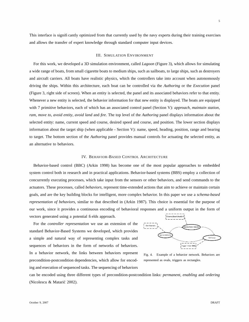
Fig. 4. Example of a behavior network. Behaviors are
represented as ovals, triggers as rectangles.
For the controller representation we use an extension of the
standard Behavior-Based Systems we developed, which provides
a simple and natural way of representing complex tasks and
sequences of behaviors in the form of networks of behaviors.
In a behavior network, the links between behaviors represent
precondition-postcondition dependencies, which allow for encod-
ing and execution of sequenced tasks. The sequencing of behaviors
can be encoded using three different types of precondition-postcondition links: permanent, enabling and ordering
(Nicolescu & Mataric 2002).
October 9, 2007 DRAFT
6
Each link type corresponds to a different time interval during which a predecessor behavior’s goals should be
achieved, with respect to activating the successor behavior. In addition, the activation of a behavior can also be
regulated by conditions that are independent of the behaviors’ goals. These conditions are encoded as triggers,
and can be dynamically created during authoring of new controllers (Section VI). Figure 4 shows an example of a
behavior network, which describes the following activity: upon firing the Start scenario trigger, the controlled boat
approaches BoatA; as soon as the distance between the controlled boat and BoatB is smaller than a threshold (as
monitored by the Distance trigger), the boat moves into maintaining station with respect to BoatB; when Trigger1
is set by the instructor, the boat moves to a specific location in the world.
In our architecture, the behaviors embed representations of a behavior’s goals in the form of abstracted environ-
mental states, which are continuously computed from the sensory data. The status of these goals is communicated
through the postcondition − precondition links between behaviors. To decide weather it should run, each behavior
checks the status of the goals from all predecessor behaviors and the status of its associated triggers. If all these
conditions are met, the behavior starts its execution. With this representation, a task sequence is completely specified
by the directed acyclic graph task network.
In our system, a controller could potentially have multiple concurrently running behaviors. For such situations, we
use the following action selection mechanism. Each behavior, including the avoid entity and avoid land behaviors,
computes a speed and a heading for the actuators. If more than one non-avoidance behavior is active at one time,
the speed and heading returned by each active behavior, represented as a vectors, are added by vector addition.
The resulting speed and heading are passed to the actuators. However, if one of the avoidance behaviors is active
along with other non-avoidance behaviors, the vector from the avoidance behavior is not fused with the other
behaviors’ output. In such a case, the other behaviors’ vectors are summed and sent to the avoidance behavior
as a “suggestion”. If the avoidance behavior finds that the suggested heading and speed do not create a risk of
collision, then the behavior will simply pass the suggested values directly to the actuators. If, on the other hand, the
avoidance behavior finds that the suggested heading and speed will cause a collision, the avoid behavior will find
an alternative heading and speed that is as close to the suggested values as possible without causing a collision.
These alternative values will then be passed directly to the actuators (Section V-C).
If both avoidance behaviors are active at the same time as other behaviors, then each avoidance behavior (land
and entities) will find an appropriate set of alternative values based on the same set of suggested values from the
other behaviors. However, instead of passing these values directly to the actuators, the outputs of the two avoid
behaviors will be fused as described above. The result will then be passed to the actuators.
V. BEHAVIOR REPERTOIRE FOR REALISTIC NAVIGATION
A. Description
The most important skill necessary for our behavior repertoire relates to vessel navigation, particularly where
realistic navigation is concerned. In the agents/robotics domain, what is most important is to design behaviors or
skills that achieve certain desired goals for the task, with little regard on the modality in which those goals are
October 9, 2007 DRAFT
7
reached. For ship handling and navigation, following the “rules of the road”’ (John V. Noel 1988) is of utmost
importance and imposes significant constraints on how the ship’s basic capabilities are designed. An additional
constraint is that the level of granularity for these skills has to be appropriate to allow for the types of tasks that
the boats would need to perform.
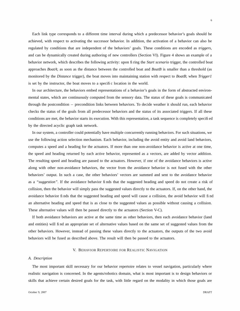
Fig. 5. Behavior Panels: Approach, Maintain Station, Move To, Ram
Based on the above requirements, we identified a set of core behaviors, which can cover the entire spectrum of
required navigation tasks (the control panels for four of the behaviors are shown in Figure 5):
• Maintain Station: This behavior encapsulates a typical navigation maneuver, in which a maneuvering ship
(such as a destroyer) maintains a certain station (distance and bearing) with respect to a reference ship (such as an
aircraft carrier). This behavior takes five parameters: 1) the reference ship, 2) the way in which the maneuver is
to be performed: constant speed, constant course or in a given amount of time, 3) the value for the maneuver (i.e.,
speed, course or time), 4) the desired stationing position in terms of distance and bearing, and 5) if the position
is relative or absolute. When executing this behavior, the maneuvering ship gets into the required station, after
which it continues to track the reference ship’s course and speed. If the reference ship changes course or speed, the
behavior re-computes the necessary control commands for the maneuvering ship, in order to maintain the desired
station.
• Approach: This behavior is similar to the Maintain Station behavior and has the same input parameters. The
difference is that the goal of this behavior is simply to get a maneuvering ship to reach a certain station (distance
and bearing) with respect to a reference ship, without maintaining that station afterward.
• Move To: The goal of this behavior is to get a maneuvering ship to a specific location in the world, in (X,
Y) coordinates. This behavior takes three main parameters: 1) the way in which the maneuver is to be performed:
with a constant speed or in a given amount of time; 2) the value for the maneuver (i.e., speed or time), and 3) the
desired (X, Y) position.
• Ram: The goal of this behavior is to have a maneuvering ship hit a target ship. This behavior takes three main
parameters: 1) the target ship, 2) the way in which the maneuver is to be performed: constant speed, constant course
October 9, 2007 DRAFT

8
or in a given amount of time, and 3) the value for the maneuver (i.e., speed, course or time). This behavior uses
the same procedure as maintain station, with the distance to target parameter set to zero.
• Fire: The goal of this behavior is to direct the weapon fire from a maneuvering ship to a target ship. The sole
parameter of this behavior is the ship toward which to direct the fire.
• Avoid Entity: The goal of this behavior is to navigate a boat such that all collisions with other boats are
avoided, in a manner consistent with the standard navigation rules (Section V-C).
• Avoid Land: The goal of this behavior is to avoid collisions with land, in a manner consistent with the standard
navigation rules (Section V-D).
As previously mentioned, simply achieving the goals of these behaviors is insufficient if the boats do not obey
the ship navigation rules. In addition, the large number of rules in the navigation domain makes very challenging
the task of implementing these rules in a simple, modular manner. The following subsections describe our approach
to implementing the main navigation rules into our behavior-based system.
B. Navigation
On an actual ship, the desired course and speed of a ship is computed using a maneuvering board, or moboard
(Figure 6a)). This allows the crew to obtain the course and/or speed that the ship should take to get into the desired
position with respect to another boat.
a) Standard maneuvering board b) Maneuvering board in Cartesian coordinates
Fig. 6. Maneuvering Board Representations
When using the moboard, the maneuvering ship is placed at the center of the board, and the location, course and
speed of the reference ship are plotted with respect to the center. With this diagram, the three modes of maneuvering
can be performed: 1) constant speed (course and time to completion are computed), 2) constant course (speed and
time to completion are computed) and 3) given time (course and speed are computed). This representation is very
useful for manual computation, such as that performed by a human operator. For our purpose, we represent the
October 9, 2007 DRAFT
9
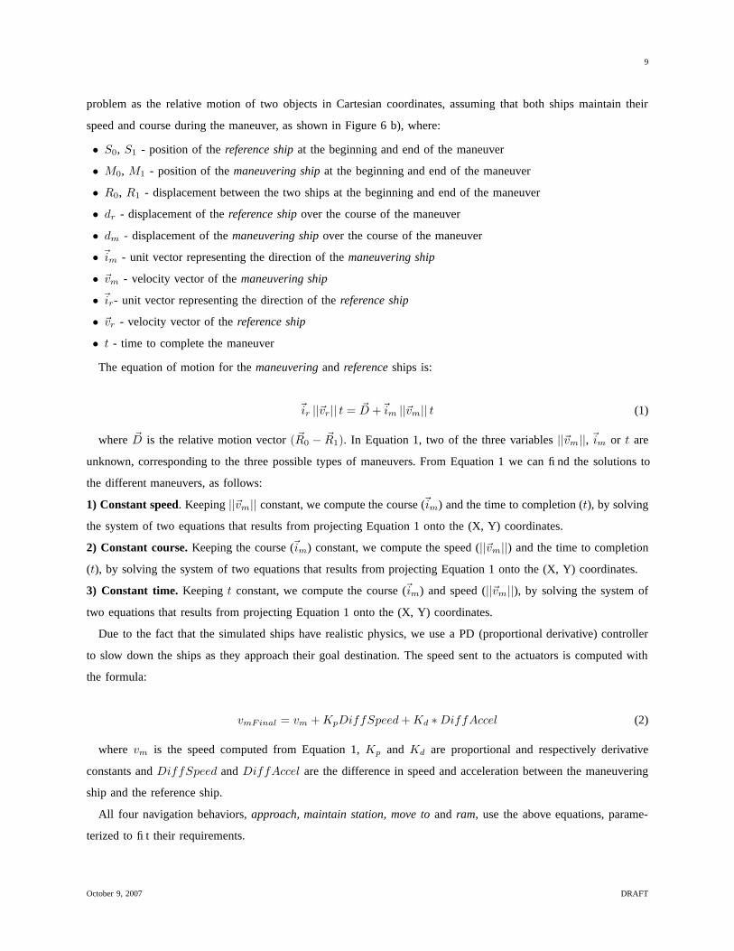
problem as the relative motion of two objects in Cartesian coordinates, assuming that both ships maintain their
speed and course during the maneuver, as shown in Figure 6 b), where:
• S0, S1 - position of the reference ship at the beginning and end of the maneuver
• M0, M1 - position of the maneuvering ship at the beginning and end of the maneuver
• R0, R1 - displacement between the two ships at the beginning and end of the maneuver
• dr - displacement of the reference ship over the course of the maneuver
• dm - displacement of the maneuvering ship over the course of the maneuver
• ~im - unit vector representing the direction of the maneuvering ship
• ~vm - velocity vector of the maneuvering ship
• ~ir- unit vector representing the direction of the reference ship
• ~vr - velocity vector of the reference ship
• t - time to complete the maneuver
The equation of motion for the maneuvering and reference ships is:
~ir ||~vr|| t = ~D +~im ||~vm|| t (1)
where ~D is the relative motion vector ( ~R0 − ~R1). In Equation 1, two of the three variables ||~vm||, ~im or t are
unknown, corresponding to the three possible types of maneuvers. From Equation 1 we can find the solutions to
the different maneuvers, as follows:
1) Constant speed. Keeping ||~vm|| constant, we compute the course (~im) and the time to completion (t), by solving
the system of two equations that results from projecting Equation 1 onto the (X, Y) coordinates.
2) Constant course. Keeping the course (~im) constant, we compute the speed (||~vm||) and the time to completion
(t), by solving the system of two equations that results from projecting Equation 1 onto the (X, Y) coordinates.
3) Constant time. Keeping t constant, we compute the course (~im) and speed (||~vm||), by solving the system of
two equations that results from projecting Equation 1 onto the (X, Y) coordinates.
Due to the fact that the simulated ships have realistic physics, we use a PD (proportional derivative) controller
to slow down the ships as they approach their goal destination. The speed sent to the actuators is computed with
the formula:
vmFinal = vm + KpDiffSpeed + Kd ∗ DiffAccel (2)
where vm is the speed computed from Equation 1, Kp and Kd are proportional and respectively derivative
constants and DiffSpeed and DiffAccel are the difference in speed and acceleration between the maneuvering
ship and the reference ship.
All four navigation behaviors, approach, maintain station, move to and ram, use the above equations, parame-
terized to fit their requirements.
October 9, 2007 DRAFT
10
C. Entity Avoidance
In typical robot/agent-based controllers, the role of the obstacle avoidance behavior is simply to avoid all obstacles.
In most cases this is achieved by turning left when there is an obstacle to the right or by turning right when there
is an obstacle to the left. To accurately mimic the actions of a human driving a ship, several important constraints
apply.
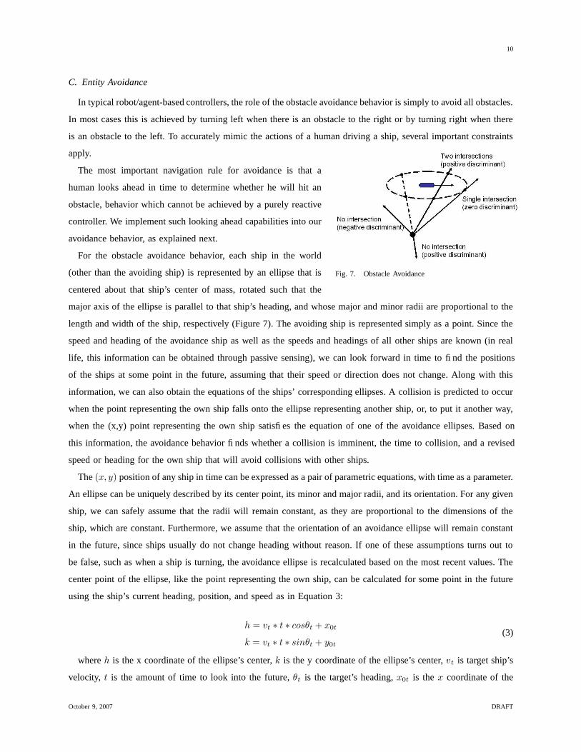
Fig. 7. Obstacle Avoidance
The most important navigation rule for avoidance is that a
human looks ahead in time to determine whether he will hit an
obstacle, behavior which cannot be achieved by a purely reactive
controller. We implement such looking ahead capabilities into our
avoidance behavior, as explained next.
For the obstacle avoidance behavior, each ship in the world
(other than the avoiding ship) is represented by an ellipse that is
centered about that ship’s center of mass, rotated such that the
major axis of the ellipse is parallel to that ship’s heading, and whose major and minor radii are proportional to the
length and width of the ship, respectively (Figure 7). The avoiding ship is represented simply as a point. Since the
speed and heading of the avoidance ship as well as the speeds and headings of all other ships are known (in real
life, this information can be obtained through passive sensing), we can look forward in time to find the positions
of the ships at some point in the future, assuming that their speed or direction does not change. Along with this
information, we can also obtain the equations of the ships’ corresponding ellipses. A collision is predicted to occur
when the point representing the own ship falls onto the ellipse representing another ship, or, to put it another way,
when the (x,y) point representing the own ship satisfies the equation of one of the avoidance ellipses. Based on
this information, the avoidance behavior finds whether a collision is imminent, the time to collision, and a revised
speed or heading for the own ship that will avoid collisions with other ships.
The (x, y) position of any ship in time can be expressed as a pair of parametric equations, with time as a parameter.
An ellipse can be uniquely described by its center point, its minor and major radii, and its orientation. For any given
ship, we can safely assume that the radii will remain constant, as they are proportional to the dimensions of the
ship, which are constant. Furthermore, we assume that the orientation of an avoidance ellipse will remain constant
in the future, since ships usually do not change heading without reason. If one of these assumptions turns out to
be false, such as when a ship is turning, the avoidance ellipse is recalculated based on the most recent values. The
center point of the ellipse, like the point representing the own ship, can be calculated for some point in the future
using the ship’s current heading, position, and speed as in Equation 3:
h = vt ∗ t ∗ cosθt + x0t
k = vt ∗ t ∗ sinθt + y0t
(3)
where h is the x coordinate of the ellipse’s center, k is the y coordinate of the ellipse’s center, vt is target ship’s
velocity, t is the amount of time to look into the future, θt is the target’s heading, x0t is the x coordinate of the
October 9, 2007 DRAFT
11
target’s current position (x coordinate of current ellipse center), and y0t is the y coordinate of the target’s current
position (y coordinate of current ellipse center).
The equation of a boat’s avoidance ellipse (centered at (h, k) and rotated by θt) is given by equation 4 below:
((xm−h)∗cosθt+(ym−k)∗sinθt)2
a2 + ((ym−k)∗cosθt−(xm−h)∗sinθt)2
b2= 1 (4)
where xm, ym, h, k, and θt are the same as above, a is the major radius of the ellipse, and b is the minor radius
of the ellipse.
We can find out if a point will fall on an ellipse by setting the xm and ym values representing the position of
the points on the ellipse to the equations for the (x, y) position of the own ship and solving for time. The result is
a quadratic equation in t, with x0m, y0m, vm, vt, θt, h, k, a, b as known parameters:
g(t) = q2t2 + q1t + q0 = 0 (5)
Based on the possible solutions of Equation 5, the following cases occur:
1) If both solutions are imaginary (negative discriminant), then there will be no intersection at any time between
the point and the ellipse, indicating no risk of collision.
2) If both solutions are equal (discriminant equal to 0), then there is only one point of intersection with the ellipse,
meaning that the own ship is traveling tangentially to the avoidance ellipse of the ship to be avoided. In this case,
there is no danger of the ships themselves colliding, as the own ship never makes its way inside the avoidance
ellipse of the other ship.
3) If the discriminant is positive, there are three possible cases: i) If both solutions are positive, the own ship will
intersect the avoidance ellipse twice: once to enter the ellipse and once more to exit it (in this case, some evasive
action must be taken to avoid a collision); ii) if both solutions are negative, there is no risk of a collision (intuitively,
this would mean that there was an intersection at some point in the past, but there is no danger in the future);
and iii) if one solution is negative and one solution is positive, then the own ship has intersected the avoidance
ellipse once in the past, and will intersect it once more in the future (this indicates that the own ship is within the
avoidance ellipse of the other ship, and must take immediate and drastic evasive maneuvers to avoid a collision
and leave the avoidance ellipse.)
If evasive action must be taken, the following options are considered. If the own ship is within the avoidance
ellipse of another ship, this is seen as an emergency situation and the own ship will try to move behind and away
from the other ship as quickly as possible. If, however, the danger of collision is sufficiently far away in the future,
the obstacle avoidance behavior can make smaller adjustments to the heading or speed of the own ship to eliminate
the danger of colliding with the other ship. To achieve this, the obstacle avoidance behavior computes a heading
and/or speed that results in a zero discriminant for Equation 5 (case 2 above), resulting in a quadratic equation in
vm, with x0m, y0m, x0t, y0t, vt, θt, a, b as known parameters. Navigation rules favor a change speed rather than
heading, thus the behavior first attempts to find a new speed that satisfies the constraint:
October 9, 2007 DRAFT

12
f(vm) = r2v2m + r1vm + r0 = 0 (6)
If the equation has two valid solutions (speeds are positive and less than or equal to the maximum speed of the
ship), the behavior returns the highest speed. If only one solution is a valid speed, that speed is used. If neither
solution is valid, then the heading must be changed to avoid a collision. To find a valid heading, the behavior first
finds whether the collision would still be imminent if the own ship turned five degrees to the left. If not, then the
behavior continues to test potential headings, in increments of five degrees, until it finds one that avoids a collision,
at which point it uses the same process to find a corresponding heading to the right of the current heading. This
results in two headings (one to the right, and one to the left) that avoid a collision. The heading closest to the
current heading is the one passed to the actuators.
The solution to avoid one ship could potentially generate collisions with others. Our approach uses a mechanism
to deal with avoiding multiple ships, as follows: for every ship on a collision course with the own ship, the avoidance
behavior puts in a list all the valid speeds and headings that will avoid that ship. After all the ships have been
analyzed and the list is built, the behavior iterates through the list and eliminates the routes that collide with other
ships. The only elements remaining in the list will be the speeds or headings that avoid collisions with all the
other ships in the simulation. Since speed changes take priority over heading changes, if there is at least one speed
remaining in the list, that speed will be passed to the actuator with the current heading. If there is more than one
potential speed in the list, the highest speed is passed to the actuators. If no speed changes remain in the list, then
the potential heading that is closest to the current heading is passed to the actuators along with the current speed.
D. Land Avoidance
To determine whether or not a ship is in danger of colliding with land, the avoid land behavior uses the speed of
the ship, as indicated in (John V. Noel 1988). This speed is to determine the approximate distance that the ship can
travel in four minutes, to check if there is any land within that distance, in all directions from the ship. If no land
is present in that area, there is no land to avoid. However, if there is land in front of the own ship, the behavior
computes a heading that will take the ship away from land and a speed that makes the nearest land be outside of
the four minute range. To achieve this, the behavior uses the distance and bearing to the nearest land in the front
180-degree field of view. The new speed is calculated to be that distance divided by four minutes, to ensure that
the nearest land will lie outside of the four minute range. The new heading is calculated to be that bearing plus
or minus 90 degrees, whichever is closer to the current heading. This ensures that instead of continuing to head
toward land, getting slower and slower until the ship grounds itself, the ship will turn parallel to the land, following
its contour until there is no more land to avoid or until the land avoidance behavior is turned off.
VI. TRIGGERS
Triggers are used to encode in a behavior network controller important situations in the training scenario. Typically,
they are used with the purpose of changing a boat’s behavior when that situation occurs.
October 9, 2007 DRAFT
13
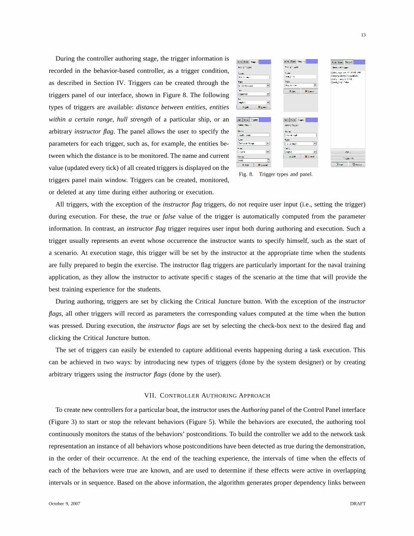
Fig. 8. Trigger types and panel.
During the controller authoring stage, the trigger information is
recorded in the behavior-based controller, as a trigger condition,
as described in Section IV. Triggers can be created through the
triggers panel of our interface, shown in Figure 8. The following
types of triggers are available: distance between entities, entities
within a certain range, hull strength of a particular ship, or an
arbitrary instructor flag. The panel allows the user to specify the
parameters for each trigger, such as, for example, the entities be-
tween which the distance is to be monitored. The name and current
value (updated every tick) of all created triggers is displayed on the
triggers panel main window. Triggers can be created, monitored,
or deleted at any time during either authoring or execution.
All triggers, with the exception of the instructor flag triggers, do not require user input (i.e., setting the trigger)
during execution. For these, the true or false value of the trigger is automatically computed from the parameter
information. In contrast, an instructor flag trigger requires user input both during authoring and execution. Such a
trigger usually represents an event whose occurrence the instructor wants to specify himself, such as the start of
a scenario. At execution stage, this trigger will be set by the instructor at the appropriate time when the students
are fully prepared to begin the exercise. The instructor flag triggers are particularly important for the naval training
application, as they allow the instructor to activate specific stages of the scenario at the time that will provide the
best training experience for the students.
During authoring, triggers are set by clicking the Critical Juncture button. With the exception of the instructor
flags, all other triggers will record as parameters the corresponding values computed at the time when the button
was pressed. During execution, the instructor flags are set by selecting the check-box next to the desired flag and
clicking the Critical Juncture button.
The set of triggers can easily be extended to capture additional events happening during a task execution. This
can be achieved in two ways: by introducing new types of triggers (done by the system designer) or by creating
arbitrary triggers using the instructor flags (done by the user).
VII. CONTROLLER AUTHORING APPROACH
To create new controllers for a particular boat, the instructor uses the Authoring panel of the Control Panel interface
(Figure 3) to start or stop the relevant behaviors (Figure 5). While the behaviors are executed, the authoring tool
continuously monitors the status of the behaviors’ postconditions. To build the controller we add to the network task
representation an instance of all behaviors whose postconditions have been detected as true during the demonstration,
in the order of their occurrence. At the end of the teaching experience, the intervals of time when the effects of
each of the behaviors were true are known, and are used to determine if these effects were active in overlapping
intervals or in sequence. Based on the above information, the algorithm generates proper dependency links between
October 9, 2007 DRAFT

14
behaviors (i.e., permanent, enabling or ordering). This learning process is described in more detail in (Nicolescu
& Mataric 2001), with application to the mobile robot domain.
The process for authoring a controller proceeds as follows:
1) The user starts the authoring by pressing the Record button.
2) If any triggers are needed, the user first creates all the triggers to be used during that session. While a scenario
is being recorded, if the user wishes to indicate changes in behavior based on some particular event in the
world, he/she navigates to the triggers panel, clicks on the check-box next to the appropriate trigger to indicate
its relevance, clicks the Critical Juncture button, and then starts the desired behavior.
3) To start a behavior, the user selects the appropriate behavior panel, selects its parameters and clicks the Start
button. At this time, the button’s label changes to Stop, which the user can press to indicate the end of that
behavior. The user activates and de-activates behaviors in sequence such as to follow the steps of the controller
task.
4) The user ends the authoring process by pressing the Save button.
During playback of the same scenario, the system will monitor the state of all triggers. When the state of the
execution trigger approaches that of the user-created trigger, the system switches the boat’s behavior according to
the demonstration. With respect to the avoidance behaviors, the system will run the controller as was indicated
during authoring: if no avoidance behaviors were included, the corresponding boat has a potential for collision
either with land or other boats.
VIII. EXPERIMENTAL RESULTS
In this section we describe the performance of our system during behavior performance testing and during
controller authoring, and also present field results from the use of our system in real navy training. This experimental
validation demonstrates the main capabilities of our system: autonomous control of multiple boats, compliance to
navigation standards and authoring of complex controllers.
A. Behavior Performance
The behaviors that involved the underlying navigation capability (approach, maintain station, ram, and move to
have been thoroughly tested throughout the experiments listed below. Their performance correctly and faithfully
demonstrated compliance to the rules of ship navigation.
We successfully tested avoid entities in numerous situations, including the following: 1) moving own-ship from
one side of stationary/moving target ship to the other side, 2) moving own-ship from one end of stationary/moving
target ship to other end, 3) moving own-ship from one side of two stationary/moving ships whose ellipses overlap
to the other side and 4) moving own-ship from one side of a crowded group of moving and stationary ships to the
other side. These represent the most probable situations to be encountered by a boat in high-traffic areas. Currently,
the system can run up to 80 ships with both avoidance and navigation behaviors in real time. This performance
provides a realism of behavior that enables an effective learning experience for the trainees.
October 9, 2007 DRAFT

15
Fig. 9. Behavior performance evaluation: Destroyer maintains station with respect to aircraft carrier; V-formation avoids big ships while moving
west.
We successfully tested the avoid land behavior in the following representative situations: 1) moving own-ship
from point far away from land to point near land, 2) moving own-ship from point near land to point farther away
from land, 3) moving own-ship to a point within a land mass (triggered avoidance and did not move onto land), 4)
moving own-ship to a point on the other side of a land mass.
By attaching Maintain station behaviors to several boats, in a layout such as required by a formation, we enabled
autonomous group behavior, for large number of boats. Currently, we can organize any number of boats (as allowed
by the computational power of the computer) in the following formations: line, row, and V-formation. The boats
involved in a group maintain their assigned formation while performing other tasks, such as moving to a new
location, or approaching a target. While performing these maneuvers, the group avoids obstacles, keeping the
formation together. Figure 9 shows a group of 5 boats in V-formation, moving to the left of a destroyer and aircraft
carrier, while performing obstacle avoidance. The bottom figure shows the formation regrouped after avoidance.
The boats can dynamically switch between formations.
B. Controller Authoring
We have performed a large number of authoring experiments with different scenarios, with all controllers being
learned correctly. Below we give detailed description of two examples, which are relevant for the training of conning
officers.
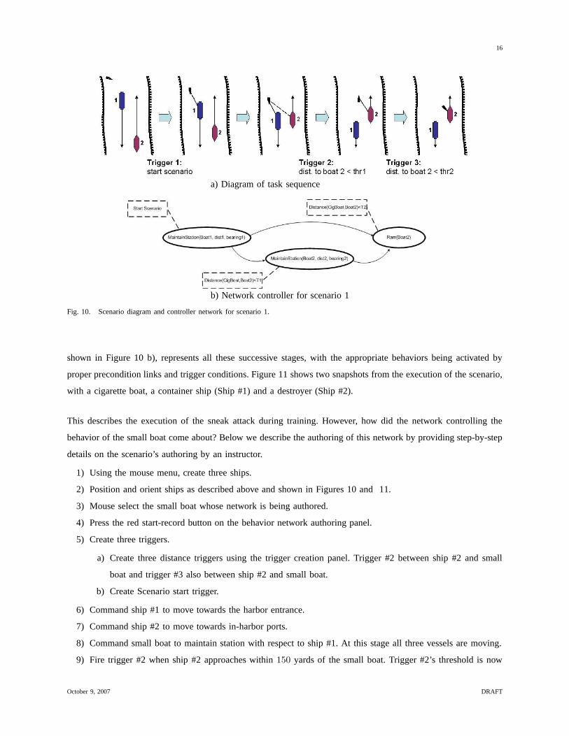
Scenario 1: sneak attack (Figure 10). After a Scenario Start trigger, a small boat moves into position with respect
to big ship #1, then maintains station with respect to it, such that it is hidden from view from ship #2. Big ship
#2 navigates in opposite direction from ship #1 in a channel. When a Distance trigger1 between the ship #1 and
ship #2 fires, the small boat switches to maintaining station ahead of ship #2. When a second Distance trigger
between the small boat and ship #2 fires, the small boat switches to ramming ship #2. The network controller,
October 9, 2007 DRAFT
16
a) Diagram of task sequence
b) Network controller for scenario 1
Fig. 10. Scenario diagram and controller network for scenario 1.
shown in Figure 10 b), represents all these successive stages, with the appropriate behaviors being activated by
proper precondition links and trigger conditions. Figure 11 shows two snapshots from the execution of the scenario,
with a cigarette boat, a container ship (Ship #1) and a destroyer (Ship #2).
This describes the execution of the sneak attack during training. However, how did the network controlling the
behavior of the small boat come about? Below we describe the authoring of this network by providing step-by-step
details on the scenario’s authoring by an instructor.
1) Using the mouse menu, create three ships.
2) Position and orient ships as described above and shown in Figures 10 and 11.
3) Mouse select the small boat whose network is being authored.
4) Press the red start-record button on the behavior network authoring panel.
5) Create three triggers.
a) Create three distance triggers using the trigger creation panel. Trigger #2 between ship #2 and small
boat and trigger #3 also between ship #2 and small boat.
b) Create Scenario start trigger.
6) Command ship #1 to move towards the harbor entrance.
7) Command ship #2 to move towards in-harbor ports.
8) Command small boat to maintain station with respect to ship #1. At this stage all three vessels are moving.
9) Fire trigger #2 when ship #2 approaches within 150 yards of the small boat. Trigger #2’s threshold is now
October 9, 2007 DRAFT

17
Fig. 11. Snapshots of the task execution in a simulated San Diego harbor. Left: Small boat gets into position w.r.t. Ship1 (distances to big
boats are shown with yellow lines). Right: View from the perspective of the small boat.
recorded as 150.
10) Command small boat to maintain station 100 yards ahead of ship #2, causing the boat to begin swinging
out from behind ship #1 and towards the bow of ship #2 (our target). This maintain station behavior and its
parameters will now be associated with trigger #2 and will activate when trigger #2 fires during execution.
11) Fire trigger #3 when the small boat is within 150 yards of ship #2 recording trigger #3’s threshold as 150.
12) Command small boat to ram ship #2. This ram behavior and its parameters are then associated with trigger
#3 and will activate when trigger #3 fires during execution.
13) Press the save button on the behavior network authoring panel.
Once saved to a file, the constructed behavior network can be used for sneak attacks in San Diego. It may also be
used in other contexts and scenarios although, as with any program, some “debugging” and fine tuning (such as
changing distance trigger thresholds) may need to be done.
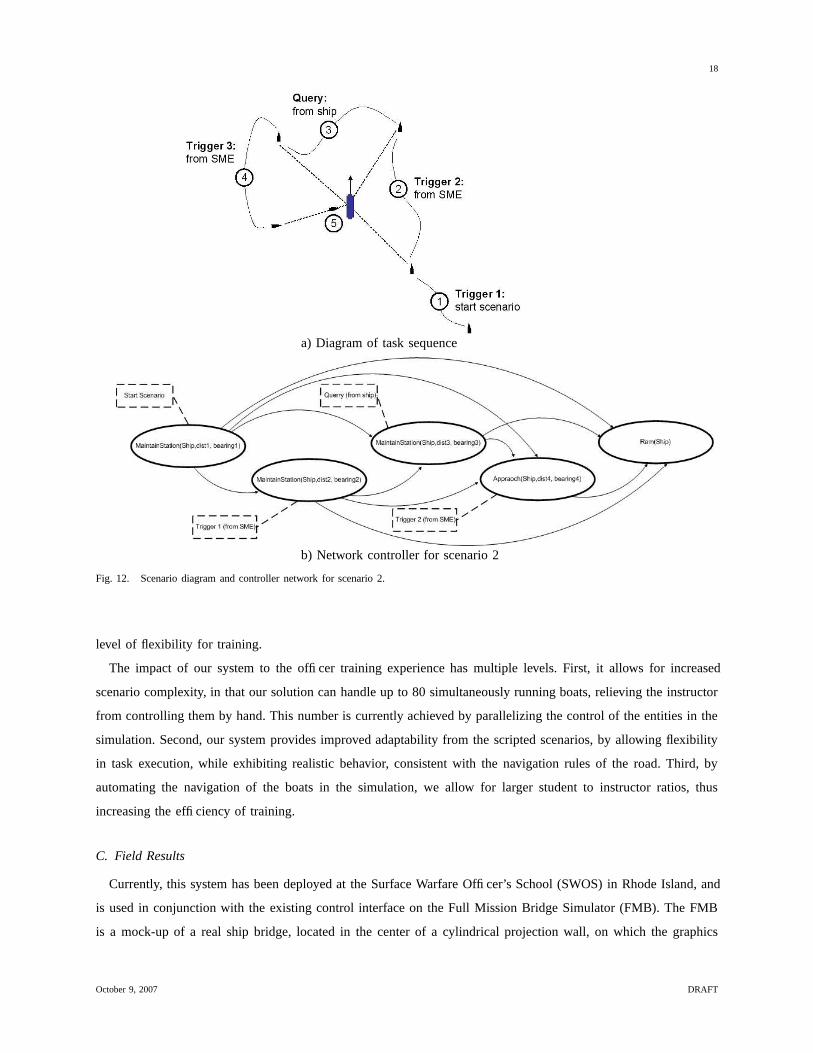
Scenario 2: zig-zag attack (Figure 10). After a Scenario Start trigger, a small boat moves into position with
respect to a big ship, then maintains distant station south-east of ship; on Trigger 1 (from SME), the small boat
changes to maintaining station north-east of big ship; upon a Query trigger from the big ship, the small boat moves
to maintaining station north-west of big ship; at Trigger 2 (from SME), the small boat approaches the big ship
at the east and then rams it. The network controller for this scenario, shown in Figure 12, encapsulates all the
above stages: the three successive steps of maintaining station with respect to the big ship, followed by approach
and ram. The first four behaviors have corresponding triggers that enable their activation, based on the conditions
demonstrated during authoring.
During training of navy officers, the learned behavior network controllers are assigned to specific boats, which
will navigate autonomously under the control of the behavior network. Using the CAT interface, the instructor has
also the opportunity to adjust variables of the controller during the execution of the scenario, providing an additional
October 9, 2007 DRAFT
18
a) Diagram of task sequence
b) Network controller for scenario 2
Fig. 12. Scenario diagram and controller network for scenario 2.
level of flexibility for training.
The impact of our system to the officer training experience has multiple levels. First, it allows for increased
scenario complexity, in that our solution can handle up to 80 simultaneously running boats, relieving the instructor
from controlling them by hand. This number is currently achieved by parallelizing the control of the entities in the
simulation. Second, our system provides improved adaptability from the scripted scenarios, by allowing flexibility
in task execution, while exhibiting realistic behavior, consistent with the navigation rules of the road. Third, by
automating the navigation of the boats in the simulation, we allow for larger student to instructor ratios, thus
increasing the efficiency of training.
C. Field Results
Currently, this system has been deployed at the Surface Warfare Officer’s School (SWOS) in Rhode Island, and
is used in conjunction with the existing control interface on the Full Mission Bridge Simulator (FMB). The FMB
is a mock-up of a real ship bridge, located in the center of a cylindrical projection wall, on which the graphics
October 9, 2007 DRAFT

19
image is projected in 360 degrees. The bridge is equipped with realistic consoles and instrumentation, which the
navy officer students use for realistic training.
To date, the following scenarios have been tested:
• Scenario 1: testing the performance of the Controller Authoring Tool by having an expert drive a destroyer
(DDG51) in an open ocean scenario, while maneuvering to try to escape from a CAT-controlled cigarette boat that
was maintaining station with respect to the DDG51. The expert could not lose the cigarette boat, which also did
not crash into any other boat in the scenario despite the expert’s efforts to make it do so.
• Scenario 2: students practiced “shouldering” with a Navy RHIB in a port transit escort scenario. Because
CAT-controlled boats avoid other entities while carrying out their major objective (in this case, maintaining station),
when the escorting Navy RHIB comes close to the maintaining cigarette boat, the RHIB essentially nudges (or
shoulders) the cigarette boat away (without actual contact). The cigarette boat then comes back to maintain station.
This behavior can only be obtained with CAT controlled boats and increased the realism of the simulation. SWOS
was impressed with this emergent behavior.
• Scenarios 3 through 5 are tactical scenarios, one in open ocean and two in littoral waters. Each of these three
scenarios had between 21 to 40 vessels most of which followed fixed paths. Simulation officers only controlled a
small subset, between two and five, of these vessels at any one time during a training. In the open ocean scenario,
although there are more than twenty vessels, they are far apart and thus relatively easy to avoid. There is no land to
avoid either. We were also able to implement formations during long transits that move boats and ships into position.
CAT maintains these boats in formation while approaching their targets. Formations work simply. A designated
lead boat is asked to approach a ship, the rest of the boats in the formation maintain station with respect to the
lead boat giving the impression of a formation. Once the boats in formation come within a threshold distance of
their targets, they split and maneuver as separate entities running different behaviors.
According to our subject matter expert, the open ocean scenario has been the most successful, since our behavior
based controllers handle open ocean avoidance best. There were still some collision problems in tight maneuvering
situations associated with littoral waters. The level of workload in this scenario has been reduced through spreading
out tasks. Currently, the hardest aspect of controlling scenarios is the weapons, but this is due to the integration
with the existing training system.
Without behavior based controllers, SWOS was restricted since the simulation officers found it difficult to control
more than four vessels simultaneously. Adding behavior based controllers allowed experimentation with adding
more boats to the scenarios. Initially, we could control more boats but our graphics were lagging with low frame
rates. Since our goals was to start running these scenarios with more boats, we have now improved the graphics
frame rate and optimized the controllers in order to be able to control up to eighty (80) entities with acceptable
frame rates.
In terms of net workload savings, since we have to control AI and weapons separately, SWOS added an instructor
for these tests. So neither instructor has to work as hard, but to date the results have been improved scenario realism
and complexity and not manpower savings. Better systems integration with existing systems at SWOS will address
October 9, 2007 DRAFT
20
this issue.
Regarding the realism of behavior of the CAT-controlled boats, one of the student groups was asked after training
if they noticed anything peculiar about boats in the scenario. The answer from the entire group was that “We thought
the boats behaved realistically”.
IX. CONCLUSION
In this paper we presented an approach to efficient and realistic design of serious game simulators, with application
to ship navigation. The goal of this system is to provide the infrastructure needed to train conning officers to drive
big ships in the context of high-traffic, potentially dangerous situations. Developing such a system poses significant
challenges and in this paper we presented an integrated solution to three of the major requirements for a successful
training simulator: 1) the efficiency of the training system, 2) the readiness of response of the boats and 3) the realism
of the behavior of the automated boat controllers. To address these challenges we developed a Controller Authoring
Tool that enables the development of intelligent, autonomous controllers that drive the behavior of a large number of
boats. This eliminates the necessity of having large number of personnel for a single student’s training, significantly
reducing the costs involved. We developed a Behavior-Based Control architecture that provides responsive automated
controllers, and we incorporated expert ship navigation knowledge to provide realistic behavior for the automated
boats. To demonstrate our approach, we presented experimental results describing the main capabilities of our
system.
X. ACKNOWLEDGMENTS
This work was supported by the Office of Naval Research under grant number N00014-05-1-0709.
REFERENCES
Abbeel, P. & Ng, A. Y. (2005), Exploration and Apprenticeship Learning in Reinforcement Learning, in ‘Proc., Intl. Conf. on Machine Learning’,
ACM Press, New York, NY, USA, pp. 1–8.
Aleotti, J., Caselli, S. & Reggiani, M. (2004), ‘Leveraging on a Virtual Environment for Robot Programming by Demonstration’, Robotics and
Autonomous Systems 47, 153–161.
Angros, R. H. (2000), Learning What to Instruct: Acquiring Knowledge from Demonstrations and foccused experimentation, PhD thesis,
University of Southern California.
Arkin, R. C. (1987), Motor Schema Based Navigation for a Mobile Robot: An Approach to Programming by Behavior, in ‘IEEE Conference
on Robotics and Automation, 1987’, pp. 264–271.
Arkin, R. C. (1998), Behavior-Based Robotics, MIT Press, CA.
Calder, R. B., Smith, J. E., Courtemarche, A. J., Mar, J. M. F. & Ceranowicz, A. Z. (1993), ModSAF Behavior Simulation and Control, in
‘Proceedings of the Second Conference on Computer Generated Forces and Behavioral Representation’.
Dautenhahn, K. & Nehaniv, C. L., eds (2002), Imitation in Animals and Artifacts, MIT Press.
Delson, N. & West, H. (1996), Robot Programming by Human Demonstration: Adaptation and Inconsistency in Constrained Motion, in ‘Proc.,
IEEE Intl. Conf. on Robotics and Automation’, Minneapolis, MN, pp. 30–36.
Gaussier, P., Moga, S., Banquet, J. & Quoy, M. (1998), ‘From Perception-Action Loops to Imitation Processes: A Bottom-up Approach of
Learning by Imitation’, Applied Artificial Intelligence Journal 12(78), 701–729.
October 9, 2007 DRAFT
21
Hayes, G. & Demiris, J. (1994), A Robot Controller Using Learning by Imitation, in ‘Proc. of the Intl. Symp. on Intelligent Robotic Systems’,
Grenoble, France, pp. 198–204.
John V. Noel, J., ed. (1988), Knight’s Modern Seamanship, John Wiley and Sons.
Kaiser, M. & Dillmann, R. (1996), Building Elementary Robot Skills from Human Demonstration, in ‘Proc., IEEE Intl. Conf. on Robotics and
Automation’, Minneapolis, Minnesota, pp. 2700–2705.
Lieberman, H. (2001a), Human-Computer Interaction for the New Millenium, ACM Press/Addison-Wesley, chapter Interfaces that Give and
Take Advice, pp. 475–485.
Lieberman, H. & Shearin, S. (2001), Intelligent Profiling by Example, in ‘Proc., ACM Conference on Intelligent User Interfaces’, Santa Fe,
NM.
Lieberman, H., ed. (2001b), Your Wish is My Command: Programming by Example, Morgan Kauffman.
Mitchel, T., Mahadevan, S. & Steinberg, L. (2005), LEAP: A Learning Apprentice for VLSI Design, in ‘Proc. Intl. Joint Conf. on Artificial
Intelligence’, pp. 573–580.
Nicolescu, M. N. & Matari c, M. J. (2001), ‘Learning and Interacting in Human-Robot Domain’, IEEE Transactions on Systems, Man, and
Cybernetics, Part A: Systems and Humans, Special Issue on Socially Intelligent Agents - The Human in the Loop 31(5), 419–430.
Nicolescu, M. N. & Matari c, M. J. (2002), A Hierarchical Architecture for Behavior-Based Robots, in ‘Proc., First Intl. Joint Conf. on Autonomous
Agents and Multi-Agent Systems’, Bologna, Italy, pp. 227–233.
Nicolescu, M. N. & Matari c, M. J. (2003), Natural Methods for Robot Task Learning: Instructive Demonstration, Generalization and Practice,
in ‘Proc., Second Intl. Joint Conf. on Autonomous Agents and Multi-Agent Systems’, Melbourne, Australia.
Ogata, H. & Takahashi, T. (1994), ‘Robotic Assembly Operation Teaching in a Virtual Environment’, IEEE Transactions on Robotics and
Automation 10(3), 391–399.
Onda, H., Suehiro, T. & Kitagaki, K. (2002), Teaching by Demonstration of Assembly Motion in VR - Non-Deterministic Search-Type Motion
in the Teaching Stage, in ‘Proc., IEEE Intl. Conf. on Intelligent Robots and Systems’, Lausanne, Switzerland, pp. 3066–3072.
Pearson, D. J., Huffman, S. B., Willis, M. B., Laird, J. E. & Jones, R. M. (1993), ‘A Symbolic Solution to Intelligent Real-Time Control’,
Robotics and Autonomous Systems 11, 279–291.
Phongsak Prasithsangaree, Joseph Manojlovich, S. H. & Lewis, M. (2004), ‘UTSAF: A Multi-Agent-Based Software Bridge for Interoperability
between Distributed Military and Commercial Gaming Simulation’, Simulation 80(12), 647–657.
Schaal, S. (1997), Learning from demonstration, in M. Mozer, M. Jordan & T. Petsche, eds, ‘Advances in Neural Information Processing Systems
9’, MIT Press, Cambridge, pp. 1040–1046.
Shavlik, J. W. (1985), Learning about Momentum Conservation, in ‘Proc., Int. Joint Conf. on Artificial Intelligence’, pp. 573–580.
Tambe, M., Johnson, L. W., Jones, R. M., Koss, F. V., Laird, J. E., Rosenbloom, P. S. & Schwamb, K. (1995), ‘Intelligent Agents for Interactive
Simulation Environments’, AI Magazine 16(1), 15–39.
Todd, D. J. (1986), Fundamentals of Robot Technology, John Wiley and Sons.
van Lent, M. & Laird, J. (1999), Learning Hierarchical Performance Knowledge by Observation, in ‘Proc. 16th International Conf. on Machine
Learning’, Morgan Kaufmann, San Francisco, CA, pp. 229–238.
Voyles, R. & Khosla, P. (2001), ‘A Multi-Agent System for Programming Robots by Human Demonstration’, Integrated Computer-Aided
Engineering 8(1), 59–67.
Yang, J., Xu, Y. & Chen, C. S. (1993), Hidden Markov Model Approach to Skill Learning and its Application in Telerobotics, in ‘Proc., Intl.
Conf. on Intelligent Robots and Systems’, Yokohama, Japan, pp. 396–402.
October 9, 2007 DRAFT