Embed Size (px)
Citation preview

Instructions for use
Title A Throughput Evaluation of an Over-Distributed Antenna System with Limited Pilot Resources
Author(s) Nakanishi, Yuki; Nishimura, Toshihiko; Ohgane, Takeo; Ogawa, Yasutaka; Ohwatari, Yusuke; Kishiyama, Yoshihisa
Citation IEICE transactions on communications, E98B(8): 1465-1473
Issue Date 2015-08
Doc URL http://hdl.handle.net/2115/59898
Rights copyright©2015 IEICE
Type article
File Information e98-b_8_1465.pdf
Hokkaido University Collection of Scholarly and Academic Papers : HUSCAP

IEICE TRANS. COMMUN., VOL.E98–B, NO.8 AUGUST 20151465
PAPER Special Section on 5G Radio Access Networks—Part I: Radio Access Technologies and System Design
A Throughput Evaluation of an Over-Distributed Antenna Systemwith Limited Pilot Resources∗
Yuki NAKANISHI†a), Student Member, Toshihiko NISHIMURA†, Takeo OHGANE†b), Members,Yasutaka OGAWA†, Fellow, Yusuke OHWATARI††, and Yoshihisa KISHIYAMA††, Members
SUMMARY A distributed antenna system, where the antennas of abase station are spatially distributed throughout the cell, can achieve betterthroughput at the cell edge than a centralized antenna system. On the otherhand, the peak throughput degrades in general because each remote an-tenna unit has only a few antennas. To achieve both high peak and cell-edgethroughputs, we need to increase the total number of antennas. However,this is not easy due to the pilot resource limitation when we use frequencydivision duplexing. In this paper, we propose using more antennas thanpilot resources. The number mismatch between antennas and signals issolved by using a connection matrix. Here, we test two types of connectionmatrix: signal-distributing and signal-switching. Simulation results showthat the sum throughput is improved by increasing the number of antennaelements per remote antenna unit under a constraint on the same number ofpilot resources.key words: distributed antenna system, multiuser MIMO system, through-put, pilot resource
1. Introduction
Currently, the rapid increase of traffic on mobile communi-cations is considered a serious problem. It is said that if thetraffic continues to increase at its current rate, the volume ofmobile traffic in 2020s will be at least 1000-fold larger thanthat in 2010 [2]. To support such a large amount of trafficand realize high speed and large capacity wireless commu-nication in the future, a fifth generation (5G) system is beingdiscussed as a new mobile communications system.
Multiple-input multiple-output (MIMO) technologyneeds to be enhanced for a 5G system. A MIMO system canincrease the channel capacity in proportion to the numberof transmit and receive antenna elements [3], but in general,the number of antennas at user terminals is difficult to in-crease due to the hardware restriction. In such a case, wecan achieve high system throughput by applying a multiuserMIMO concept [4]–[6] where a base station has many trans-mit antennas and communicates with several users simulta-neously. As an extension of this concept, recently, a verylarge or massive MIMO system has been proposed that can
Manuscript received December 8, 2014.Manuscript revised March 3, 2015.†The authors are with the Graduate School of Information
Science and Technology, Hokkaido University, Sapporo-shi, 060-0814 Japan.††The authors are with NTT DOCOMO, INC., Yokosuka-shi,
239-8536 Japan.∗This paper was partly presented at IEEE PIMRC 2014 [1].
a) E-mail: [email protected]) E-mail: [email protected]
DOI: 10.1587/transcom.E98.B.1465
achieve extremely high capacity [7].Although most massive MIMO concepts are discussed
for use in a centralized antenna system (CAS) where anten-nas of a base station are located at the center of the cell,the concept is theoretically applicable to a distributed an-tenna system (DAS) [8]–[10] as well. The DAS is known toimprove the cell-edge throughput performance. Thus, it issuitable to maintain the fairness of user throughput. Fortu-nately, a concept of cloud radio access network [11], whichis a key technology for 5G, provides a DAS-friendly archi-tecture.
However, the DAS has a disadvantage that the peakthroughput tends to be lower than that of the CAS. In theDAS, the antenna elements are distributed to several re-mote antenna units (RAUs). Thus, the number of antennasper RAU is obviously smaller than the number of antennasat the CAS base station. If the total number of antennasis not enough, each RAU may have only a couple of an-tennas. Thus, the spatial multiplexing capability becomessmall even near the RAU due to the rank deficiency. Fromthis point of view, the massive MIMO concept is suitablefor DAS because the number of antennas per RAU also be-comes large enough.
Any precoding methods require the channel state in-formation (CSI) per transmit antenna. Therefore, how weobtain the CSI in massive MIMO systems is a big issue. Toknow the CSI, we send an individual pilot sequence fromeach transmit antenna. In the massive MIMO scenario dis-cussed by Rusek et al. [12], the total number of user ter-minals as well as their receive antennas is assumed to bemuch smaller than the number of antennas at the base sta-tion. This means that uplink CSI estimation requires muchfewer pilot resources than the downlink one. Therefore, insuch a case, time division duplexing (TDD) is consideredto leverage the channel reciprocity obtaining the transmitCSI [7], [12], [13].
In the frequency division duplexing (FDD), on theother hand, the channel reciprocity cannot be exploited andthe CSI is learned from feedback from user terminals usingdownlink pilot resources. Thus, a very large number of pilotresources is required to obtain the downlink CSI in mas-sive MIMO scenarios. This is generally unacceptable due toenormous overhead [14], [15].
In the paper, we consider breaking the one-on-one re-lationship between the transmit antenna and pilot resourceand making the total number of transmit antennas exceed
Copyright c© 2015 The Institute of Electronics, Information and Communication Engineers

1466IEICE TRANS. COMMUN., VOL.E98–B, NO.8 AUGUST 2015
the number of pilot resources [1]. This means that we canknow the CSI only for some transmit antennas or that theCSI will be contaminated. The imperfect CSI has entirelydifferent effects on the CAS and DAS. In the CAS case, theimportance of each antenna element in precoding is almostequal on average since the location is almost the same from amacroscopic point of view. Thus, the imperfect CSI stronglydegrades the throughput performance due to imperfect pre-coding. In contrast, the importance of each antenna elementin the DAS highly depends on the location of RAU. For ex-ample, the CSI of antennas at the RAUs far from existingusers is not expected to affect the precoding accuracy veryseverely. This property may be considered another advan-tage of the DAS. Therefore, we propose a DAS where thenumber of antennas greatly exceeds pilot resources. We callthis over-distributed antenna system (O-DAS) hereinafter.In this paper, the throughput performance of O-DAS is nu-merically evaluated and compared with those of the conven-tional DAS and CAS.
The number of spatial multiplexed streams, i.e., thenumber of transmit signals, is not larger than the numberof pilot resources. Thus, there is a mismatch between thenumber of transmit antennas and the number of signals. Toreconcile this mismatch, we use a connection matrix. Here,two types of matrices are considered. One is the distribut-ing type. Each signal is distributed to one or more antennaelements located at different RAU(s). This requires no apriori knowledge to construct the connection matrix. How-ever, several signals are transmitted from ineffective RAUs.Consequently, some power loss occurs. The other one is theswitching type. If the user location is available, we can se-lect the RAUs that best concentrate the signal power. Weexamine how these types improve the peak throughput aswell as the cell-edge throughput in the O-DAS.
The rest of the paper is organized as follows. In Sect. 2,we introduce the channel model considered in this paper. InSect. 3, the concept of the O-DAS and each type of connec-tion matrix are described. In Sect. 4, we formulate multiuserMIMO precoding in the O-DAS with the connection matrix.The throughput performance of the proposed O-DAS is nu-merically evaluated and conclusions are drawn in Sects. 5and 6, respectively.
2. Channel Model
In this paper, we consider a multiuser MIMO system in FDDwhere each of Nu users has Nr receive antennas as shown inFig. 1. The number of antenna elements at the base stationis Nt. In the CAS, Nt antennas are centralized in the centerbase station, whereas they are distributed to several RAUsin the DAS. Note that the RAUs are connected to the centralunit by high-speed fronthaul such as optic fibers [16] andthus function as a single system. Here, we assume the idealcase where delay in fronthaul can be ignored†.
†Our objective in this paper is to compute an upper bound. Theimpact of control delay should be a future work.
Fig. 1 Multiuser MIMO system.
We denote the channel matrix between the base stationand the kth user as H(k) ∈ CNr×Nt
H(k) =
⎡⎢⎢⎢⎢⎢⎢⎢⎢⎢⎢⎢⎢⎢⎢⎢⎢⎢⎢⎣
h(k)11 h(k)
12 · · · h(k)1Nt
h(k)21 h(k)
22 · · · h(k)2Nt
...... h(k)
i j
...
h(k)Nr1 h(k)
Nr2 · · · h(k)Nr Nt
⎤⎥⎥⎥⎥⎥⎥⎥⎥⎥⎥⎥⎥⎥⎥⎥⎥⎥⎥⎦, (1)
where h(k)i j ∈ C (i = 1, 2, . . . , Nr, j = 1, 2, . . . , Nt) expresses
the (i, j)th channel response for the kth user. We clearlyignore the time-dispersive channel for the sake of simplicity.However, the following discussion can be applied to multi-carrier systems without loss of generality.
We assume that h(k)i j is given by a product of an i.i.d.
complex Gaussian random variable (where the mean is zeroand the variance is one) and a coefficient G expressing thepath loss and shadowing loss. Denoting a path loss constantas α and a random variable for shadowing loss as η [dB],which is normally distributed with zero mean and a standarddeviation of σs, we obtain
G = d−α10−η/10, (2)
where d is a distance from a user terminal to the base stationor one of the RAUs [17].
3. Concept of an Over-Distributed Antenna System
3.1 Potential Problem of a Multiuser MIMO DAS
When the number of total antennas at the base station is lim-ited, each RAU has only a few antennas in the DAS. In aseven-RAUs case, for example, each RAU has only Nt/7antennas. Thus, the user near one of the RAUs can see onlya small number of antennas, so rank deficiency may occur asshown in Fig. 2. This is the reason the DAS cannot providevery high peak throughput.
To improve the peak throughput of the DAS, we mustincrease the number of total antennas at the base station.However, this usually requires pilot resources equal to thenumber of antennas for channel estimation when we as-sume FDD systems. Specifically, when we express the num-ber of pilot sequences used for channel estimation as Nc,Nc ≥ Nt should be ensured. A large number of pilot se-quences causes the serious pilot transmission overhead and

NAKANISHI et al.: A THROUGHPUT EVALUATION OF AN OVER-DISTRIBUTED ANTENNA SYSTEM WITH LIMITED PILOT RESOURCES1467
Fig. 2 Rank difference between CAS and DAS.
degrades transmission efficiency. Thus, it is very difficultto increase the number of antennas per RAU under the con-straint of Nc ≥ Nt.
3.2 Over-Distributed Antenna System
Considering the above problem, we propose the multiuserMIMO DAS with a much larger number of transmit anten-nas than pilot resources (Nc < Nt), i.e., O-DAS. This sys-tem is only allowed to use up to Nc dimensional channelinformation at the base station. This means that the numberof spatially-multiplexed signals is not larger than Nc either.Therefore, the assignment of Nc signals to Nt transmit anten-nas must be considered. Here, let us express the RF outputsignal vector of the central unit as x = [x1, x2, . . . , xNc ]
T
and the output signal vector of the actual antenna elementsas x′ = [x′1, x′2, . . . , x′Nt
]T . These relationships can be ex-pressed by using the connection matrix T as
x′ = Tx, (3)
where T ∈ CNt×Nc indicates a connection status on each out-put signal from the central unit to transmit antennas. Thismeans that the transmission method and the performance inthe O-DAS are determined by the structure of the connectionmatrix T. In this section, we explain two types of transmis-sion methods and structures of the connection matrix.
3.2.1 Signal Distributing
First, we consider the case where the base station cannotacquire or does not use information on the location of userterminals. In the O-DAS (and DAS as well), the RAUs arelocated apart from each other. Therefore, each user seesonly a few RAUs. In other words, the signals transmittedfrom RAUs on the far side of the cell may not reach the userterminals. This fact implies that the same signal (and thesame pilot sequence) among several RAUs can be reused.The signal reuse corresponds to distributing the signal todifferent RAUs. Thus, we call this transmission type signaldistributing.
We explain the concept using the example shown inFig. 3. Here, the central unit has three RF ports. In gen-eral, each port is connected to an individual antenna elementas shown in Fig. 3(a). In the signal distributing example,each port is connected to two different antennas as shown
Fig. 3 Concept of signal distributing.
Fig. 4 Footprint of RF output port 1.
in Fig. 3(b). This doubles the number of antenna elementswithout increasing the number of pilot resources.
The effect of signal distributing may be expressed bya footprint (i.e., a coverage area) of each antenna port asshown in Fig. 4. The antennas transmitting distributed sig-nals cover two different circular areas with a single RF out-put port. This means that the requirement on the user loca-tion to receive the signal x1 is eased. This may be said tobe a very attractive feature of the O-DAS. Although the in-terference occurs among the distributed pilot signals whenwe estimate channels, we regard the antennas transmittingthe same signal as a virtual antenna and use its effectiveCSI for transmission, as will be discussed later in Sect. 4.1.If the signal distribution is applied to the CAS, the effec-tive antenna pattern changes and thus is no longer omni-directional. Note that the transmission power is also dis-tributed. If the power is divided equally, the transmissionpower per antenna port becomes the inverse of the numberof distributed ports connected to the same RF port of thecentral unit.
The relationship between the RF output ports of thecentral unit and the actual antenna elements in Fig. 3(b) isexpressed as

1468IEICE TRANS. COMMUN., VOL.E98–B, NO.8 AUGUST 2015
⎡⎢⎢⎢⎢⎢⎢⎢⎢⎢⎢⎢⎢⎢⎢⎢⎣
x′1x′2...
x′6
⎤⎥⎥⎥⎥⎥⎥⎥⎥⎥⎥⎥⎥⎥⎥⎥⎦= T
⎡⎢⎢⎢⎢⎢⎢⎢⎣x1
x2
x3
⎤⎥⎥⎥⎥⎥⎥⎥⎦ =
⎡⎢⎢⎢⎢⎢⎢⎢⎢⎢⎢⎢⎢⎢⎢⎢⎢⎢⎢⎢⎢⎢⎢⎢⎢⎢⎣
1/√
2 0 00 0 1/
√2
0 1/√
2 01/√
2 0 00 0 1/
√2
0 1/√
2 0
⎤⎥⎥⎥⎥⎥⎥⎥⎥⎥⎥⎥⎥⎥⎥⎥⎥⎥⎥⎥⎥⎥⎥⎥⎥⎥⎦
⎡⎢⎢⎢⎢⎢⎢⎢⎣x1
x2
x3
⎤⎥⎥⎥⎥⎥⎥⎥⎦ . (4)
Here, T has only one non-zero element in each row, and thevector norm of each column is normalized. In addition, thesame RF port of the central unit is not connected more thanonce within the same RAU to maintain the omni-directionalantenna pattern. Note that the structure of T is fixed regard-less of the locations of user terminals. In the DAS case, T isgiven by the identity matrix.
3.2.2 Signal Switching
Next, we consider the case where the base station can useinformation on the location of user terminals. Again, RAUson the far side of the cell may be insignificant from a sig-nal level viewpoint. Therefore, in this situation, we do notactivate such RAUs. Only Nc antenna ports are selectedfrom Nt ones and connected to the RF ports of the centralunit. This concept is explained using the example shown inFig. 5. Here, we have six antenna ports. On the other hand,three RF ports of the central unit are available. Then, we se-lect three antenna ports and connect them to the central unit.Other antenna ports are disabled. For antenna selection, theuser location information is used. The selection process isdone on a distance basis with a round robin. Specifically,an arbitrary antenna at the nearest RAU for user 1 is se-lected first. Then, the selection proceeds to user 2, and soon. When the round is completed, the process is repeatedagain until the number of selected antennas reaches Nc.
The relationship between the RF output ports of thecentral unit and the actual antenna elements in Fig. 5 is ex-pressed as
Fig. 5 Concept of signal switching.
⎡⎢⎢⎢⎢⎢⎢⎢⎢⎢⎢⎢⎢⎢⎢⎢⎣
x′1x′2...
x′6
⎤⎥⎥⎥⎥⎥⎥⎥⎥⎥⎥⎥⎥⎥⎥⎥⎦= T
⎡⎢⎢⎢⎢⎢⎢⎢⎣x1
x2
x3
⎤⎥⎥⎥⎥⎥⎥⎥⎦ =
⎡⎢⎢⎢⎢⎢⎢⎢⎢⎢⎢⎢⎢⎢⎢⎢⎢⎢⎢⎢⎢⎢⎢⎣
1 0 00 1 00 0 00 0 00 0 10 0 0
⎤⎥⎥⎥⎥⎥⎥⎥⎥⎥⎥⎥⎥⎥⎥⎥⎥⎥⎥⎥⎥⎥⎥⎦
⎡⎢⎢⎢⎢⎢⎢⎢⎣x1
x2
x3
⎤⎥⎥⎥⎥⎥⎥⎥⎦ . (5)
Here, T has only one “1” element in each column, and itappears to be a sparse matrix. In contrast to the signal dis-tributing method, the structure of T is changed when thelocations of user terminals change.
4. Multiuser MIMO Precoding with Proposed Meth-ods
In multiuser MIMO systems, one way to prevent the interuser interference (IUI) is precoding. Here, we use blockdiagonalization (BD) [18]–[20], which is a technique toachieve perfect nulling. To perform precoding at the basestation, the channel matrix must be known at the base sta-tion. Obviously, the estimated results are affected by signaldistributing and signal switching. However, the difference intransmission methods depends on the structure of the con-nection matrix. Therefore, we can formulate these methodsin the same way using T. We describe the precoding proce-dure in the signal distributing and signal switching step bystep.
4.1 Channel Estimation
Here we consider an example case using a con-stant amplitude zero auto-correlation (CAZAC) sequence[p1, p2, . . . , pNc ] the length of which is Nc. It is a cyclicshift sequence, thus Nc patterns of Nc dimensional row vec-tors are applicable as pilot sequences:
p1 = [p1, p2, . . . , pNc ]
p2 = [p2, p3, . . . , p1]
...
pNc = [pNc , p1, . . . , pNc−1].
(6)
These vectors have a property for the inner product as ex-pressed by
pkpHl =
⎧⎪⎪⎨⎪⎪⎩Nc l = k
0 l � k. (7)
Next, let us describe a channel estimation process withthe CAZAC sequences. By using Eq. (6), the matrix con-sisting of the Nc vectors is represented by
P = [pT1 pT
2 · · · pTNc
]T . (8)
This matrix has a property:
PPH = NcINc , (9)
where INc denotes the Nc-dimensional identity matrix.

NAKANISHI et al.: A THROUGHPUT EVALUATION OF AN OVER-DISTRIBUTED ANTENNA SYSTEM WITH LIMITED PILOT RESOURCES1469
Fig. 6 Channel sounding and feedback process.
The pilot sequences are transmitted from the antennaelements at the base station or RAUs. If we use the sig-nal distributing or signal switching technique, the pilot se-quences are distributed in accordance with the connectionmatrix T. Thus, the pilot sequence matrix P′ ∈ CNt×Nc trans-mitted from the actual antenna elements is given by
P′ = TP. (10)
At the kth user terminal, the received signal sequencecorresponding to the pilot sequence duration is written as
Y(k) = H(k)TP, (11)
where Y(k) ∈ CNr×Nc is the received signal matrix and thenoise is omitted for a simple notation. By multiplyingEq. (11) from the right hand side by PH , we have
Y(k)PH = NcH(k)T. (12)
Defining estimated channel as H̃(k) ∈ CNr×Nc , we obtain
H̃(k) =1
NcY(k)PH = H(k)T. (13)
Note that we estimate not the pure channel matrix H(k) butthe effective channel matrix. The estimated channel is fedback to the base station as shown in Fig. 6.
4.2 BD Precoding
BD completely suppresses the IUI by directing nulls to otherusers. Now, we have an estimated channel matrix H̃(k) for1 ≤ k ≤ Nu. If the CSI is perfectly estimated, H̃(k) = H(k)Tholds as in Eq. (13).
The BD precoding matrix W(k)BD is calculated on the
basis of the estimation results H̃(1),. . . , H̃(Nu), and then thedimension of precoding matrix becomes Nc × Nw whereNw = Nc − (Nu − 1)Nr. The obtained precoding matrix sat-isfies
H̃(l)W(k)BD = O for l � k, (14)
where O ∈ CNr×Nw is the zero matrix. Thus, no IUI isobserved at any user terminal. By using Eq. (13), we canrewrite this relationship as
Fig. 7 Transmitter structure.
H(l)TW(k)BD = O for l � k. (15)
Therefore, we may regard the effective BD precoding matrixas TW(k)
BD ∈ CNt×Nw .In this paper, we apply an eigenmode transmission [21]
to each equivalent single-user MIMO channel without IUI.Then, the equivalent channel of the kth user after BD pre-coding is written as H̃(k)W(k)
BD = H(k)TW(k)BD. The eigen-
mode precoding matrix W(k)EM ∈ CNw×Nr is calculated with
this equivalent channel H(k)TW(k)BD. The total transmit pre-
coding matrix combining BD and eigenmode transmissionis expressed as
W(k)TX =W(k)
BDW(k)EMA(k), (16)
where (A(k))2 is an Nr-dimensional diagonal matrix for atransmit power control derived from the water-filling theo-rem. Note that each column vector of W(k)
BD and W(k)EM is nor-
malized. In addition, the total transmit power is set to oneand thus the transmit power for each user becomes 1/Nu.
The whole transmitter structure including the connec-tion matrix is expressed as shown in Fig. 7.
4.3 Achievable Sum Throughput Evaluation
In the paper, we evaluate the system performance usingachievable sum throughput of the multiuser MIMO systemwith BD. The received signal vector for the kth user be-comes
y(k)(t) = H(k)TNu∑l=1
W(l)TXs(l)(t) + z(k)(t), (17)
where s(k)(t) is the transmit signal vector for the user k atthe time index t and z(k)(t) is the noise vector composed ofcomplex Gaussian noise.
Defining an equivalent channel matrix considering thetotal transmit precoding matrix as H(k,l)
E = H(k)TW(l)TX (l =
1, 2, . . . , Nu), we can rewrite Eq. (17) as
y(k)(t) =Nu∑l=1
H(k,l)E s(l)(t) + z(k)(t). (18)
The achievable sum throughput Γ [bps/Hz] consideringthe IUI [22] is expressed as
Γ =
Nu∑k=1
log2 det(INr +
(R(k)
NI
)−1H(k,k)
E
(H(k,k)
E
)H), (19)

1470IEICE TRANS. COMMUN., VOL.E98–B, NO.8 AUGUST 2015
where R(k)NI is the covariance matrix of IUI [22]. R(k)
NI is givenby
R(k)NI =
Nu∑l=1, l�k
H(k,l)E
(H(k,l)
E
)H+ σ2INr , (20)
where σ2 is the noise power.In this paper, we assume that effective CSI in Eq. (13)
is perfectly estimated in order to focus on effects of signaldistributing and signal switching. Thus, no IUI is observed,and so we have
R(k)NI = σ
2INr . (21)
5. Numerical Evaluation
5.1 Simulation Environment
We applied computer simulations to evaluate performanceof the O-DAS with two types of transmission methods de-scribed above. The simulation parameters are shown in Ta-ble 1. The number of RAUs for the DAS and O-DAS isseven as shown in Fig. 8. Thus, the number of antenna el-ements per RAU is Nt/7. Each channel response betweenantennas except the path loss and shadowing is given as tobe i.i.d. quasi-static Rayleigh distribution†. The total trans-mit power and noise level are determined by the cell edgeSNR of CAS to be 0 dB in a single-antenna case consider-ing only path loss††.
The user terminals are uniformly randomly locatedin the cell, and a complementary cumulative distributionfunction (CCDF) is obtained by calculating the averagesum throughput with Eq. (19) at each position. We evalu-ated CCDF performances for each transmission method bychanging Nc and Nt. Note that Nt is limited to 49 at most inthe case of Nc = 7 to prevent the port reuse within the RAU.When we use the signal distributing method, the port con-nection patterns in the connection matrix T are determinedrandomly for each trial. The connection matrix in the signalswitching method is determined in accordance with a rulebased on user locations as described in Sect. 3.2.2.
5.2 Achievable Sum Throughput Performance
First, we compare the performance of the O-DAS with thatof the conventional DAS. Figure 9 shows the CCDF curvesof sum throughputs in the O-DAS case of Nt = 21, Nc = 14with signal distributing and signal switching and in the con-ventional DAS case of Nt = 14, Nc = 14. For reference,
†The channel correlation between different antennas in thesame RAU or base station may not be zero in the actual situations.The specific correlation value depends on the heights of antennasand surrounding buildings. Such conditions may differ between theCAS and DAS. In the paper, we simply assumed the uncorrelatedchannels as an ideal case.††These parameters are commonly used in O-DAS, DAS, and
CAS.
Fig. 8 RAU positions. R denotes the cell radius.
Table 1 Simulation parameters.
Number of remote antenna units 7
Number of TX antennas Nt 7, 14, 21,. . . , 70
Number of users Nu 2
Number of RX antennas Nr 3
Channel statistics Quasi-static Rayleigh fading
Path loss constant α 3.5
Standard deviation of shadowing σs 7 dB
Number of trials for sum300throughput (fast fading) averaging
Number of trials (locations) for30000CCDF calculation
Fig. 9 CCDF of average sum throughput (Nc=14).
we also show the performance in the CAS case of Nt = 14,Nc = 14. All above cases use the same number of pilotsequences (Nc = 14). The performances in the O-DAScases are improved in the whole range, and the gain becomeslarger, especially in the large sum throughput region, than inthe DAS case. This result clearly indicates that it is effectiveto increase the number of transmit antennas at each RAUeven when pilot resources are limited.
Next, let us discuss the relationship between the num-ber of transmit antennas and pilot sequences applying signaldistributing and signal switching. Here, we use 10% value
NAKANISHI et al.: A THROUGHPUT EVALUATION OF AN OVER-DISTRIBUTED ANTENNA SYSTEM WITH LIMITED PILOT RESOURCES1471
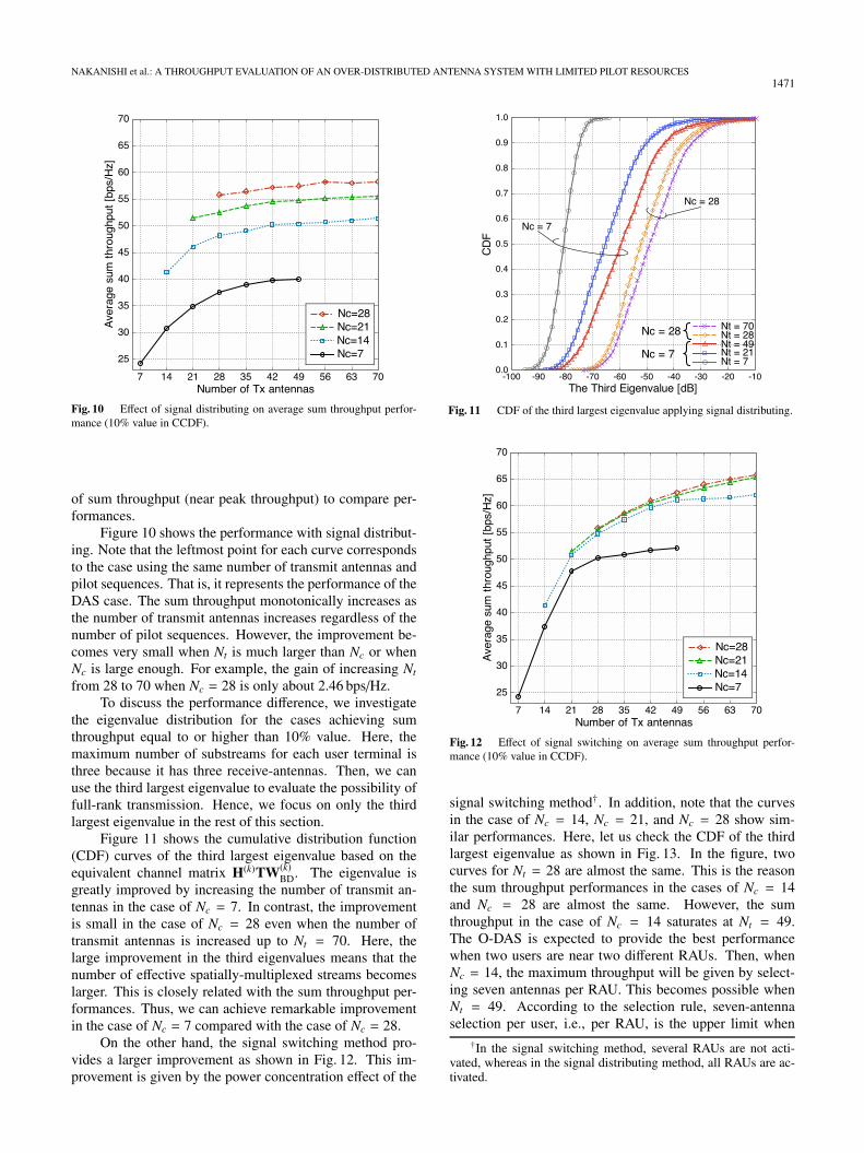
Fig. 10 Effect of signal distributing on average sum throughput perfor-mance (10% value in CCDF).
of sum throughput (near peak throughput) to compare per-formances.
Figure 10 shows the performance with signal distribut-ing. Note that the leftmost point for each curve correspondsto the case using the same number of transmit antennas andpilot sequences. That is, it represents the performance of theDAS case. The sum throughput monotonically increases asthe number of transmit antennas increases regardless of thenumber of pilot sequences. However, the improvement be-comes very small when Nt is much larger than Nc or whenNc is large enough. For example, the gain of increasing Nt
from 28 to 70 when Nc = 28 is only about 2.46 bps/Hz.To discuss the performance difference, we investigate
the eigenvalue distribution for the cases achieving sumthroughput equal to or higher than 10% value. Here, themaximum number of substreams for each user terminal isthree because it has three receive-antennas. Then, we canuse the third largest eigenvalue to evaluate the possibility offull-rank transmission. Hence, we focus on only the thirdlargest eigenvalue in the rest of this section.
Figure 11 shows the cumulative distribution function(CDF) curves of the third largest eigenvalue based on theequivalent channel matrix H(k)TW(k)
BD. The eigenvalue isgreatly improved by increasing the number of transmit an-tennas in the case of Nc = 7. In contrast, the improvementis small in the case of Nc = 28 even when the number oftransmit antennas is increased up to Nt = 70. Here, thelarge improvement in the third eigenvalues means that thenumber of effective spatially-multiplexed streams becomeslarger. This is closely related with the sum throughput per-formances. Thus, we can achieve remarkable improvementin the case of Nc = 7 compared with the case of Nc = 28.
On the other hand, the signal switching method pro-vides a larger improvement as shown in Fig. 12. This im-provement is given by the power concentration effect of the
Fig. 11 CDF of the third largest eigenvalue applying signal distributing.
Fig. 12 Effect of signal switching on average sum throughput perfor-mance (10% value in CCDF).
signal switching method†. In addition, note that the curvesin the case of Nc = 14, Nc = 21, and Nc = 28 show sim-ilar performances. Here, let us check the CDF of the thirdlargest eigenvalue as shown in Fig. 13. In the figure, twocurves for Nt = 28 are almost the same. This is the reasonthe sum throughput performances in the cases of Nc = 14and Nc = 28 are almost the same. However, the sumthroughput in the case of Nc = 14 saturates at Nt = 49.The O-DAS is expected to provide the best performancewhen two users are near two different RAUs. Then, whenNc = 14, the maximum throughput will be given by select-ing seven antennas per RAU. This becomes possible whenNt = 49. According to the selection rule, seven-antennaselection per user, i.e., per RAU, is the upper limit when
†In the signal switching method, several RAUs are not acti-vated, whereas in the signal distributing method, all RAUs are ac-tivated.

1472IEICE TRANS. COMMUN., VOL.E98–B, NO.8 AUGUST 2015
Fig. 13 CDF of the third largest eigenvalue applying signal switching.
Nu = 2. Thus, the gain of increasing the number of an-tenna elements for 49 ≤ Nt ≤ 70 is almost the same whenNc = 14.
In contrast, when Nc = 28, the maximum throughputwill be given by selecting 14 antennas per RAU. This be-comes possible when Nt = 98. Therefore, the sum through-put performance in the case of Nc = 28 still improves for49 ≤ Nt ≤ 70. We can confirm this property from the curvesof the third largest eigenvalue for Nt = 70 in the cases ofNc = 14 and Nc = 28 as shown in Fig. 13.
Finally, let us show the specific gains of increas-ing Nt with signal distributing and signal switching. Thegain of doubling Nt with signal distributing is about 6.58bps/Hz, and that with signal switching is about 13.03 bps/Hzfor Nc = 7, whereas these gains are reduced to about2.36 bps/Hz and 8.22 bps/Hz for Nc = 28. Thus, we cansay that it is particularly effective to apply signal distribut-ing or signal switching to the system with a small numberof pilot resources.
6. Conclusions
In this paper, we have studied an O-DAS with two trans-mission methods and evaluated its performance using theachievable sum throughputs given by BD precoding. Weimproved the sum throughput performance by increasing thenumber of transmit antennas even when the pilot resourceswere limited. The effect is especially large in a system witha small number of pilot resources. Although signal switch-ing yields larger improvements than signal distributing, bothmethods can provide a visible gain in the sum throughputperformance. Therefore, we may say that which method weshould adopt depends only on the availability of user loca-tion information. The optimality of connection matrices forthe signal distributing and signal switching should be dis-cussed in further studies.
References
[1] Y. Nakanishi, T. Nishimura, T. Ohgane, Y. Ogawa, Y. Ohwatari,and Y. Kishiyama, “Antenna splitting in a distributed antenna sys-tem for a multiuser MIMO transmission,” Proc. IEEE PIMRC’14,Sept. 2014.
[2] “5G radio access: Requirements, concept and technologies,” DO-COMO 5G White Paper, NTT DOCOMO, July 2014.
[3] E. Telatar, “Capacity of multi-antenna gaussian channels,” Eur.Trans. Telecommun., vol.10, no.6, pp.585–595, Nov./Dec. 1999.
[4] Q.H. Spencer, C.B. Peel, A.L. Swindlehurst, and M. Haardt, “Anintroduction to the multi-user MIMO downlink,” IEEE Commun.Mag., vol.42, no.10, pp.60–67, Oct. 2004.
[5] D. Gesbert, M. Kountouris, R.H. Heath, Jr., C.-B. Chae, and T.Salzer, “Shifting the MEMO paradigm,” IEEE Signal Process. Mag.,vol.24, no.5, pp.36–46, Sept. 2007.
[6] G. Caire and S. Shamai, “On the achievable throughput of a mul-tiantenna Gaussian broadcast channel,” IEEE Trans. Inf. Theory,vol.49, no.7, pp.1691–1706, July 2003.
[7] T.L. Marzetta, “Noncooperative cellular wireless with unlimitednumbers of base station antennas,” IEEE Trans. Wireless Commun.,vol.9, no.11, pp.3590–3600, Nov. 2010.
[8] A.A.M. Saleh, A. Rustako, and R. Roman, “Distributed antennasfor indoor radio communications,” IEEE Trans. Commun., vol.35,no.12, pp.1245–1251, Dec. 1987.
[9] W. Choi and J. Andrews, “Downlink performance and capacityof distributed antenna systems in a multicell environment,” IEEETrans. Wireless Commun., vol.6, no.1, pp.69–73, 2007.
[10] M.V. Clark, T.M. Willis, L.J. Greenstein, A.J. Rustako, Jr., V.Erceg, and R.S. Roman, “Distributed versus centralized antenna ar-rays in broadband wireless networks,” Proc. IEEE VTS 53rd Vehic-ular Technology Conference, Spring 2001 (Cat. No.01CH37202),pp.33–37, May 2001.
[11] “C-RAN the road towards green RAN,” White paper version 3.0,China Mobile Research Institute, Dec. 2013.
[12] F. Rusek, D. Persson, B.K. Lau, E.G. Larsson, T.L. Marzetta, andF. Tufvesson, “Scaling up MIMO: Opportunities and challengeswith very large arrays,” IEEE Signal Process. Mag., vol.30, no.1,pp.40–60, Jan. 2013.
[13] H.Q. Ngo, E.G. Larsson, and T.L. Marzetta, “Massive MU-MIMOdownlink TDD systems with linear precoding and downlink pilots,”Proc. 2013 51st Annual Allerton Conference on Communication,Control, and Computing (Allerton), pp.293–298, Oct. 2013.
[14] S.A. Ramprashad and G. Caire, “Cellular vs. network MIMO: Acomparison including the channel state information overhead,” Proc.2009 IEEE 20th International Symposium on Personal, Indoor andMobile Radio Communications, pp.878–884, Sept. 2009.
[15] S.A. Ramprashad, G. Caire, and H.C. Papadopoulos, “Cellular andnetwork MIMO architectures: MU-MIMO spectral efficiency andcosts of channel state information,” Proc. 2009 Conference Recordof the Forty-Third Asilomar Conference on Signals, Systems andComputers, pp.1811–1818, Nov. 2009.
[16] F. Diehm, P. Marsch, and G. Fettweis, “The FUTON prototype:Proof of concept for coordinated multi-point in conjunction witha novel integrated wireless/optical architecture,” Proc. 2010 IEEEWireless Communication and Networking Conference Workshops,pp.1–4, April 2010.
[17] A. Goldsmith, Wireless Communication, Cambridge UniversityPress, 2005.
[18] Q.H. Spencer, A.L. Swindlehurst, and M. Haardt, “Zero-forcingmethods for downlink spatial multiplexing in multiuser MIMOchannels,” IEEE Trans. Signal Process., vol.52, no.2, pp.461–471,2004.
[19] M. Rim, “Multi-user downlink beamforming with multiple transmitand receive antennas,” Electron. Lett., vol.38, no.25, pp.1725–1726,2002.

NAKANISHI et al.: A THROUGHPUT EVALUATION OF AN OVER-DISTRIBUTED ANTENNA SYSTEM WITH LIMITED PILOT RESOURCES1473
[20] K. Nishimori, T. Hiraguri, and H. Makino, “Transmission rateby user antenna selection for block diagonalization based mul-tiuser MIMO system,” IEICE Trans. Commun., vol.E97-B, no.10,pp.2118–2126, Oct. 2014.
[21] K. Miyashita, T. Nishimura, T. Ohgane, Y. Ogawa, Y. Takatori, andK. Cho, “High data-rate transmission with eigenbeam-space divi-sion multiplexing (E-SDM) in a MIMO channel,” Proc. IEEE 56thVehicular Technology Conference, vol.3, pp.1302–1306, Sept. 2002.
[22] Yi Song and S.D. Blostein, “MIMO channel capacity in co-channelinterference,” Proc. 21st Biennial Symposium on Communications,pp.220–224, Kingston, Canada, May 2002.
Yuki Nakanishi received a B.E. degreein information science and technology fromHokkaido University, Sapporo, Japan, in 2013.He is currently a master’s course student at theGraduate School of Information Science andTechnology, Hokkaido University. His interestsare in signal processing for distributed antennasystems. He is a student member of IEEE.
Toshihiko Nishimura received his B.S.in physics in 1992, his M.S. in physics in1994, and his Ph.D. in electronics engineeringin 1997 all from Hokkaido University, Sapporo,Japan. He joined the Graduate School of En-gineering (presently reorganized as the Gradu-ate School of Information Science and Technol-ogy) at Hokkaido University in 1998, where heis currently an assistant professor of the Gradu-ate School of Information Science and Technol-ogy. His current research interests are in MIMO
systems using smart antenna techniques. Dr. Nishimura received the YoungResearchers’ Award of IEICE in 2000, the Best Paper Award from IEICEin 2007, and the Best Magazine Paper Award in 2011 from the IEICE Com-munications Society. He is a member of IEEE.
Takeo Ohgane received his B.E., M.E., andPh.D. in electronics engineering from HokkaidoUniversity, Sapporo, Japan, in 1984, 1986, and1994. He was with the Communications Re-search Laboratory of the Ministry of Posts andTelecommunications from 1986 to 1992. Hewas on assignment at the ATR Optical and Ra-dio Communications Research Laboratory from1992 to 1995. Since 1995, he has been withHokkaido University, where he is an associateprofessor. He was at the Centre for Communi-
cations Research of the University of Bristol, U.K., as a visiting fellowfrom 2005–2006. His interests are in MIMO signal processing for wirelesscommunications. Dr. Ohgane received the Young Researchers’ Award ofIEICE in 1990, the IEEE AP-S Tokyo Chapter Young Engineer Award in1993, the Best Paper Award from IEICE in 2007, and the Best MagazinePaper Award in 2011 from the IEICE Communications Society. He is amember of IEEE.
Yasutaka Ogawa received his B.E., M.E.,and Ph.D. from Hokkaido University, Sapporo,Japan, in 1973, 1975, and 1978. Since 1979,he has been with Hokkaido University, wherehe is currently a full professor at the Gradu-ate School of Information Science and Technol-ogy. From 1992–1993, he was with the Elec-troScience Laboratory of Ohio State University,U.S.A., as a visiting scholar, on leave fromHokkaido University. His interests are in adap-tive antennas, mobile communications, super-
resolution techniques, and MIMO systems. Dr. Ogawa received the Yasu-jiro Niwa outstanding paper award in 1978, the Young Researchers’ Awardof IEICE in 1982, the Best Paper Award from IEICE in 2007, the BestMagazine Paper Award in 2011 from the IEICE Communications Society,and the Achievement Award from IEICE in 2014. He is a fellow of IEEE.
Yusuke Ohwatari received his B.E. in elec-tronics engineering, M.E. in information sci-ence and technology, and his Ph.D. in engi-neering from Hokkaido University, Hokkaido,Japan, in 2005, 2007, and 2013. Since 2007,he has been with the Research Laboratories,NTT DOCOMO, INC., Kanagawa, Japan. Hiscurrent interest is multiple-input and multiple-output (MIMO) systems for mobile communi-cation systems. He received the IEEE VTSJapan Chapter Young Researcher’s Encourage-
ment Award in 2006, the Best Paper Award from IEICE in 2007, the YoungResearchers’ Award from IEICE in 2012, and the 2011 IEICE RCS ActiveResearch Award. He is a member of IEEE.
Yoshihisa Kishiyama received his B.E.,M.E., and Ph.D. from Hokkaido University,Sapporo, Japan, in 1998, 2000, and 2010. In2000, he joined NTT DOCOMO, INC. His re-search interests include physical layer technolo-gies for 3GPP LTE enhancements and futureradio access (5G) concept for efficient use ofhigher frequency bands. He was a recipient ofthe IEICE Young Engineer Award in 2004 andthe ITU Association of Japan Award in 2012.He is currently a manager in the Radio Access
Development Department of NTT DOCOMO. He is a member of IEEE.


![Approaching Throughput-optimality in Distributed …arXiv:1011.3594v1 [cs.NI] 16 Nov 2010 1 Approaching Throughput-optimality in Distributed CSMA Scheduling Algorithms with Collisions](https://img.dokumen.tips/doc/110x75/5e66c8d9b51fc3670b3024e3/approaching-throughput-optimality-in-distributed-arxiv10113594v1-csni-16-nov.jpg)