Embed Size (px)
Citation preview

A Term Paper Submitted To The Production Manager, Nestle Waters,
Nestle Nig. Plc, Agbara.During a One Month Intern as A
Water Treatment Supervisor,By: Salawu, Hameed Olanrewaju
NYSC/OG/11C/2465.April, 2012.

1. What is pH: pH is the power of hydrogen ion. In chemistry, it is a measure of the acidity or basicity of an aqueous solution. Pure water is neutral with a pH close to 7.0 at 25 degree Celsius. Solutions with a pH less than 7 are said to be acidic and solutions with pH greater than 7 are said to be basic. Water coming from the deep well usually as an high pH range of 5-6, this unusual high pH is as a result of constituent gases reacting with the water thus forming an acidic water.At the water enters the stripping tank and comes in contacts with air, through the process of aeration, oxygen molecules’ oxidizes and liberate carbon dioxide the major cause of acidity in the water hence, after the process of aeration, the water leaving the stripping tank as its pH stabilized into the range above 6.5. At the finished line of Nestle Pure Life water the expected pH range of the finished product mustn’t exceed the norms of 6.5-8.0.
Relation between p [OH] and p [H] (red = acid region, blue = basic region)

Some typical pH values
2. Chemistry Aspect of Stripping Tank: the stripping tank is a large vessel in which an aerated device is fixed into it for aeration. Water from the deep well enters the stripping tank and comes in contacts with air. Aeration is achieved by passing the water through the air by means of paddle wheels. This process increases the oxygen content which helps to dispel other dissolved gasses such as CO2 and to oxidize compound dissolved or suspended in water. And as such water leaving the stripping tank is of pH range of 6.98 and above and all oxidizable substances taken care of.
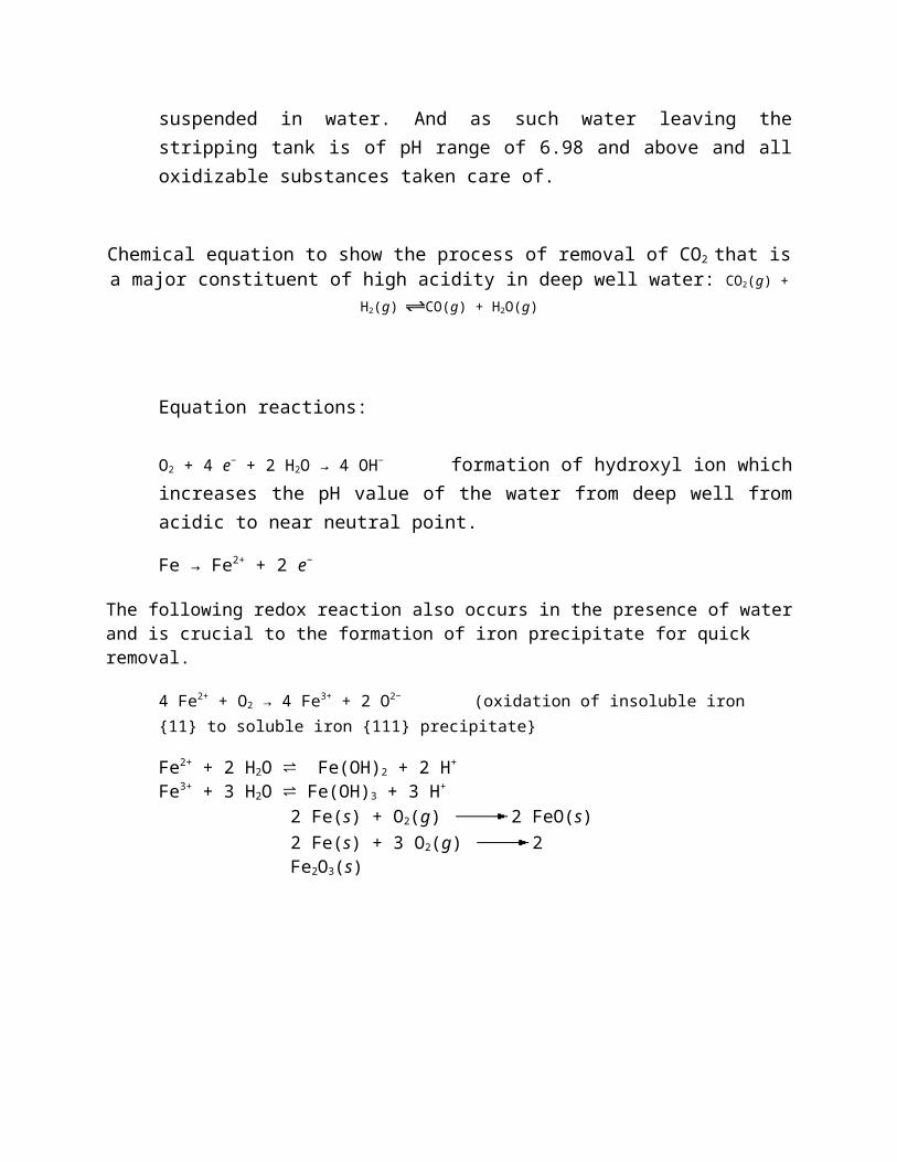
Chemical equation to show the process of removal of CO2 that is a major constituent of high acidity in deep well water: CO2(g) + H2(g) CO(g) + H2O(g)
Equation reactions:
O2 + 4 e− + 2 H2O → 4 OH− formation of hydroxyl ion which increases the pH value of the water from deep well from acidic to near neutral point.
Fe → Fe2+ + 2 e−
The following redox reaction also occurs in the presence of water and is crucial to the formation of iron precipitate for quick removal.
4 Fe2+ + O2 → 4 Fe3+ + 2 O2− (oxidation of insoluble iron {11} to soluble iron {111} precipitate}
Fe2+ + 2 H2O ⇌ Fe(OH)2 + 2 H+ Fe3+ + 3 H2O ⇌ Fe(OH)3 + 3 H+
2 Fe(s) + O2(g) 2 FeO(s) 2 Fe(s) + 3 O2(g) 2 Fe2O3(s)

3. Role of Sand Filters: sand filters are used for water purification, its works by providing the particulate solids with many opportunities to be captured on the surface of a sand grain. As fluid flow through the porous sand along a torturous route, the particulate comes close to sand grains. This can be captured by one of several mechanisms such as direct collision, Vander Waals, surface charge.
Nestle water has two functional sand filters; water coming from the stripping tanks are pumped via pumps into the two sand filters which does the role of sedimentation, filtration

and oxidation. Its also helps to free from water pathogens, taste and odor.


Basically the 3 major role of the sand filter is: 1. Sedimentation. 2. Oxidation. 3. Filtration.
1. Sedimentation: is a physical water treatment process used to settle out suspended solids in water under the influence of gravity. Sedimentation in potable water treatment generally follows a step of chemical coagulation and flocculation, which allows grouping particles together into flocs of a bigger size. This increases the settling speed of suspended solids and allows settling colloids. Water purification is the process of removing undesirable chemicals, biological contaminants, suspended solids and gases from contaminated water. The goal is to produce water fit for a specific purpose. Most
water is purified for human consumption (drinking water) but water purification may also be designed for a variety of other purposes, including meeting the requirements of medical, pharmacological, chemical and industrial applications. In general the methods used include physical processes such as filtration, sedimentation, and distillation, biological processes such as slow sand filters or biologically active carbon, chemical processes such as flocculation and chlorination and the use of electromagnetic radiation such as ultraviolet light.
2. Filtration: is commonly the mechanical or physical operation which is used for the separation of solids from fluids (liquids or gases) by interposing a medium through which only the fluid can pass. Oversize solids in the fluid are retained, but the separation is not complete; solids will be contaminated with some fluid and filtrate will contain fine particles (depending on the pore size and filter thickness). Filtration is also used to describe some biological processes, especially in water treatment and sewage treatment in which undesirable constituents are removed by absorption into a biological film grown on or in the filter medium.
3. Oxidation: Iron and manganese are unaesthetic parameters present mostly in groundwater, causing unwanted precipitation and color. Iron removal is based on the precipitation of dissolved iron (Fe2+) into its oxidized form (Fe3+), as Fe(OH)3 or Fe2O3.
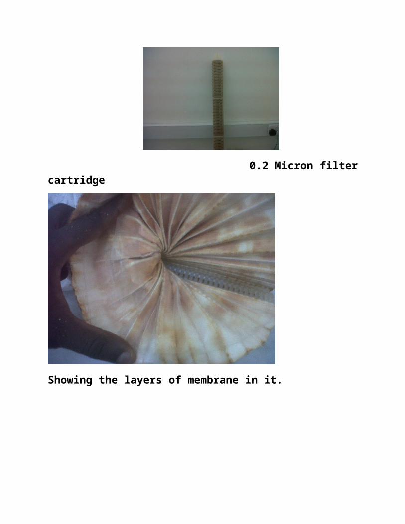
4 0.2 Micron-Filters:
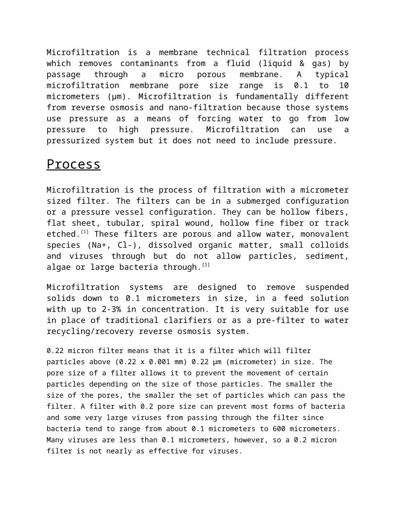
Microfiltration is a membrane technical filtration process which removes contaminants from a fluid (liquid & gas) by passage through a micro porous membrane. A typical microfiltration membrane pore size range is 0.1 to 10 micrometers (µm). Microfiltration is fundamentally different from reverse osmosis and nano-filtration because those systems use pressure as a means of forcing water to go from low pressure to high pressure. Microfiltration can use a pressurized system but it does not need to include pressure.
ProcessMicrofiltration is the process of filtration with a micrometer sized filter. The filters can be in a submerged configuration or a pressure vessel configuration. They can be hollow fibers, flat sheet, tubular, spiral wound, hollow fine fiber or track etched.[1] These filters are porous and allow water, monovalent species (Na+, Cl-), dissolved organic matter, small colloids and viruses through but do not allow particles, sediment, algae or large bacteria through.[1]

Microfiltration systems are designed to remove suspended solids down to 0.1 micrometers in size, in a feed solution with up to 2-3% in concentration. It is very suitable for use in place of traditional clarifiers or as a pre-filter to water recycling/recovery reverse osmosis system.
0.22 micron filter means that it is a filter which will filter particles above (0.22 x 0.001 mm) 0.22 µm (micrometer) in size. The pore size of a filter allows it to prevent the movement of certain particles depending on the size of those particles. The smaller the size of the pores, the smaller the set of particles which can pass the filter. A filter with 0.2 pore size can prevent most forms of bacteria and some very large viruses from passing through the filter since bacteria tend to range from about 0.1 micrometers to 600 micrometers. Many viruses are less than 0.1 micrometers, however, so a 0.2 micron filter is not nearly as effective for viruses.
The o.22 micron filter is housed inside its housing immediately after the storage tank 7B and is called Operational Prerequisite Point, at this point; Nestle Water assumes that the water is free of any microbial activities that could impact on Nestle Pure Life water.
Considering each micron filter as a whole, the membrane is made up of 5 layers with the first layer been a coarse layer and the final layer made up of seal-sieve layer that serves at the last point of sieving. The basic function of the filter is to trap down microbes and sediments present in the water. Water enters through the 0.22 micron filter through a downward stream enters through the hole where its sieves out and moves via the upstream out of the micron filter.
Periodically an integrity test is usually carried out on the micron filter to ascertain their effectiveness by passing air through the filters as against water and seeing the rate of permissibility through the filters. If the filters are clogged up there is a pressure build and the pressure decay rises above the set bar of 83mbar indicating that the filters no longer serves its primary function of trapping.
CartridgeMicrofiltration what is integrity Test?
Meaning:
This is a test performed on micron filters in other to ensure the highest Possible assurance of filter integrity and removal efficiency.
Objectives:
To ascertain the assurance of filter retention and ensure product quality.
Factors Influencing Integrity testing
Temperature: During IT test, the temperature inside the filter housing must not vary more than ±10C
Filter Wetting: It is important that the filter medium is fully wetted prior to a forward Flow test. Incomplete wetting will result in inaccurate measurements
To demonstrate that the system is performing to specification.
When to perform an integrity test?
Whenever a new set of micron filters are installed in a housing
To ensure the new installation is integral
After every chemical procedure:
Bi-Weekly after cleaning and sanitization
Especially after hot water at 850C sanitization
After long term storage, just before filling starts
To ensure integrity has been maintained
When post-Final Filter tests show increasing micro counts
Are the filters by-passing / non-integral?
Is there post-filter contamination?

0.2 Micron filter cartridge
Showing the layers of membrane in it.

The most finite of the 5 layers
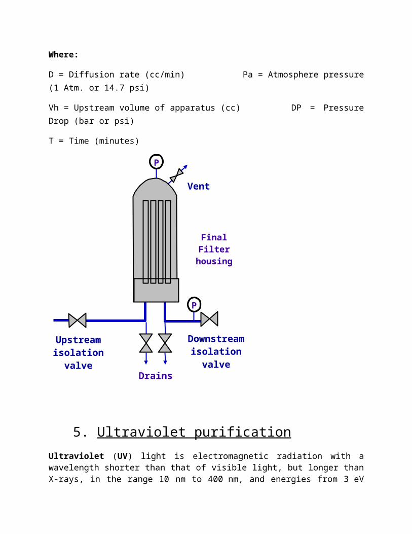
Pressure Hold / Pressure Decay The Pressure Hold Test, also known as pressure decay or pressure-drop test, is a variation of the diffusion test. In this test, a highly accurate gauge is used to monitor upstream pressure changes due to gas diffusion through the filter. Because there is no need to measure gas flow downstream of the filter, any risk to downstream sterility is eliminated.
The pressure hold value is dependent on the diffusion flow and upstream volume. It can be calculated using the following equation:
Where:
D = Diffusion rate (cc/min) Pa = Atmosphere pressure (1 Atm. or 14.7 psi)
Vh = Upstream volume of apparatus (cc) DP = Pressure Drop (bar or psi)
T = Time (minutes)
5. Ultraviolet purification Ultraviolet (UV) light is electromagnetic radiation with a wavelength shorter than that of visible light, but longer than X-rays, in the range 10 nm to 400 nm, and energies from 3 eV to 124 eV. It is named because the spectrum consists of electromagnetic waves with frequencies higher than those that humans identify as the color violet. These frequencies are invisible to humans, but visible to a number of insects and birds. They are also indirectly visible, by causing fluorescent materials to glow with visible light.
P
P
Final Filter housing
Drains
Upstreamisolation
valve
Downstreamisolation
valve
Vent

UV light is found in sunlight and is emitted by electric arcs and specialized lights such as black lights. It can cause chemical reactions, and causes many substances to glow or fluoresce. Most ultraviolet is classified as non-ionizing radiation. The higher energies of the ultraviolet spectrum from wavelengths about 10 nm to 120 nm ('extreme' ultraviolet) are ionizing, but this type of ultraviolet in sunlight is blocked by normal di-oxygen in air, and does not reach the ground.[1] However, the entire spectrum of ultraviolet radiation has some of the biological features of ionizing radiation, in doing far more damage to many molecules in biological systems than is accounted for by simple heating effects (an example is sunburn). These properties derive from the ultraviolet photon's power to alter chemical bonds in molecules, even without having enough energy to ionize atoms.
Water turbidity (i.e., the amount of suspended & colloidal solids contained in the water to be treated) must be low, such that the water is clear, for UV purification to work well. Also, water treated with UV still has the microbes present in the water, only with their means for reproduction turned "off". In the event that such UV-treated water containing neutered microbes is exposed to visible light (specifically, wavelengths of light over 330-500 nm) for any significant period of time, a process known as photo reactivation can take place, where the possibility for repairing the damage in the bacteria's reproduction DNA arises, potentially rendering them once more capable of reproducing and causing disease.[9] UV-treated water must therefore not be exposed to visible light for any significant period of time after UV treatment, before consumption, to avoid ingesting reactivated and dangerous microbes. For long term usage, the issue of obtaining batteries to power portable water purification UV devices can be a concern.
Another concern with UV portable water purification is that some pathogens are hundreds of times less sensitive to UV light than others. Protozoan cysts were once believed to be among the least sensitive, however recent studies have proved otherwise, demonstrating that both Cryptosporidium and Giardia are deactivated by a UV dose of just 6 mJ/cm sq.[10] However, EPA regulations and other studies show that it is viruses that are the limiting factor of UV treatment, requiring a 10-30 times greater dose of UV light than Giardia or Cryptosporidium[11] .[12]
Furthermore, studies have shown that UV doses at the levels provided by common portable UV units are effective at killing Giardia and that there was no evidence of repair and reactivation of the cysts.
Fortunately, Giardia are among the easiest pathogens to filter out of water. A viable two-step portable water purification approach, providing greater protection than UV purification alone, is to first filter suspect water, thereby removing the larger pathogens, prior to using UV purification.
Ultraviolet fluorescent lamps
Fluorescent lamps without a phosphorescent coating to convert UV to visible light emit ultraviolet light with two peaks at 253.7 nm and 185 nm due to the peak emission of the mercury within the bulb. Eighty-five to ninety percent of the UV produced by these lamps is at 253.7 nm, while only five to ten percent is at 185 nm. Germicidal lamps use quartz (glass) doped with an additive to block the 185 nm wavelength. With the addition of a suitable phosphor (phosphorescent coating), they can be modified to produce a UVA, UVB, or visible light spectrum (all fluorescent tubes used for domestic and commercial lighting are mercury UV emission bulbs at heart).
Such low-pressure mercury lamps are used extensively for disinfection, and in standard form have an optimum operating temperature of about 30 degrees Celsius. Use of a mercury amalgam allows operating temperature to rise to 100 degrees Celsius, and UVC emission to about double or triple per unit of light-arc length. These low-pressure lamps have a typical efficiency of approximately thirty to thirty-five percent, meaning that for every 100 watts of electricity consumed by the lamp, it will produce approximately 30-35 watts of total UV output. UVA/UVB emitting bulbs also sold for other special purposes, such as reptile-keeping.
EFFECT OF ULTRAVIOLETWhen a micro-organism is exposed to UV-C, the nuclei of the cells are modified, due to photolytic processes. In result, cell division and, by extension, reproduction is prevented.
UV-C PRODUCTIONThe Ultra Violet source is basically a fused silica quartz tube, typically l5mm to 25mm diameter ranging from 100mm-1200mm long. The inert gas with which the tube is filled, provides the primary discharge and the necessary action to excite and vaporize the miniscule deposits of mercury within.
The low pressure UV lamp is only capable of producing lines at 185nm and 254 nm. An increase in the current supplied would cause the UV lamp to rapidly heat up thus increasing the mercury pressure to produce the typical medium pressure spectral output shown in Diagram 2.

ULTRAVIOLET DOSEThe UV dose is the product of UV intensity (expressed as energy per unit surface area) and residence time.
Therefore: DOSE = I x T
This is commonly expressed as 1mJ/cm2=1000 micro Watt second/cm2
The minimum dose expressed by Willand gives the user the guaranteed assurance of success. Average and cumulative doses offered by others depend on turbulent flow characteristics which can disappear when flow is variable.
Willand recommend the appropriate UV dose for each application taking into account water quality, arc tube ageing, industry specifications, as well as microbiological standards.
DOSE / DESTRUCTION RELATIONSHIPThe relationship between the dose and the destruction achieved of a target micro-organism can be summarized as follows:
N/No = e-KD
Where:N = Initial Number of target organisms No = Number of target organisms after treatment K = Constant associated with target organisms D = Dose
From the above relationship doubling of the dose applied will increase the destruction by a factor of 10. Therefore doubling the dose required for 90% destruction will produce 99% destruction of the target organism. tripling the dose will produce a 99.9% destruction of the target organism and so on.
Some 90% destruction values are shown in Fig. 3 and the relationship between UV dose and destruction are shown in Fig. 4
Fig. 3 - DOSE REQUIREMENTS - COMMON MICRO-ORGANISMS
SpeciesDose
(mJ/cm2)
Bacillus subtilis (spore) 12.0
Clostridium tetani 4.9
Legionella Pneumophilla 2.04
Pseudonomas aeruginosa 5.5
Streptococcus feacalis 4.5
Hepatitis A virus 11.0
Hepatitis Poliovirus 12.0
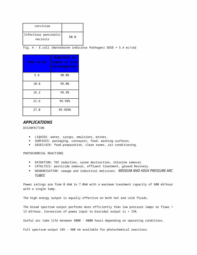
Saccharomyces cervisiae 6.0
Infectious pancreatic necrosis 60.0
Fig. 4 - E.coli (Waterborne indicator Pathogen) DOSE = 5.4 mJ/cm2
Dose mJ/cm2Reduction in
number of live microorganisms
5.4 90.0%
10.8 99.0%
16.2 99.9%
21.6 99.99%
27.0 99.999%
APPLICATIONSDISINFECTION
LIQUIDS: water, syrups, emulsions, brines. SURFACES: packaging, conveyors, food, working surfaces. GASES/AIR: food preparation, clean rooms, air conditioning.
PHOTOCHEMICAL REACTIONS
OXIDATION: TOC reduction, ozone destruction, chlorine removal. CATALYSIS: pesticide removal, effluent treatment, ground Recovery. DEODORISATION: sewage and industrial emissions. MEDIUM AND HIGH PRESSURE ARC TUBES
Power ratings are from 0.4kW to 7.0kW with a maximum treatment capacity of 600 m3/hour with a single lamp.
The high energy output is equally effective on both hot and cold fluids.
The broad spectrum output performs more efficiently than low pressure lamps on flows > 13 m3/hour. Conversion of power input to biocidal output is > 15%.
Useful arc tube life between 4000 - 8000 hours depending on operating conditions.
Full spectrum output 185 - 480 nm available for photochemical reactions.

LOW PRESSURE LAMPSIdeal for low flow situations with power ratings from 15w to 200w.
Single wavelength output at 254 nm.
Conversion to UV-C typically 30% - 35%.
120 - 200 watt lamps unaffected by water temperatures.
IRRADIATION CHAMBERSThe disinfection process involves the exposure of fluids with microbiological contamination to a UV energy source which is mounted centrally in an irradiation chamber.
Lenntech have always believed that correct chamber design is a significant part of effective disinfection and to this end computer modeling is used to establish turbulent flow, which ensures good mixing and balanced exposure at high and low flows and residence time characteristics.
Lenntech UV Systems design equipments so that the dose is AT THE WALL, AT THE END OF LAMP LIFE. This protects the process from possible inadequate treatment which may occur through short circuiting when average and cumulative doses are is used.
High quality internal finishing avoids shadowing and other bacterial traps.
Chambers have integrally fabricated sample ports, drain and air vents as standard.
The inlet and outlet orientation, size and end termination are to customers specification to aid installation.
SINGLE ARC TUBE CONFIGURATIONSingle arc tube configuration greatly enhances performance. One high intensity lamp is capable of disinfecting up to 600m3/hour. UV intensity monitoring is positive, simple, effective and proven.
Multi-tube designs utilizing quantities of low pressure lamps housed in one chamber present both hydraulic and mechanical problems. Maintenance is time consuming and expensive. Baffles are required to introduce turbulence and through the shadowing effect of these it is possible for untreated water to pass through the chamber shielded from the monitor.
UV INTENSITY MONITORINGWilland intensity monitors respond to UV-C. The monitor is the customer's safeguard the unit is operating at efficient output. When low UV-C output threshold is reached an alarm is initiated. Monitor output can be linked to BEM or PLC units to ensure optimum plant operation.

References.
1. ^ Bates, Roger G. Determination of pH: theory and practice. Wiley, 1973.
2. ^ a b c d Covington, A. K.; Bates, R. G.; Durst, R. A. (1985). "Definitions of pH scales, standard reference values, measurement of pH, and related terminology". Pure Appl. Chem. 57 (3): 531–542. DOI:10.1351/pac198557030531. http://www.iupac.org/publications/pac/1985/pdf/5703x0531.pdf.
3. ^ Sorensen, S. P. L., Enzymstudien. II, Über die Messung und die Bedeutung der Wasserstoffionenkonzentration bei enzymatischen Prozessen, Biochem. Zeitschr., 1909, vol. 21, pp. 131–304. Two other publications appeared in 1909 one in French and one in Danisch
4. ^ a b c "Carlsberg Group Company History Page". Carlsberggroup.com. http://www.carlsberggroup.com/Company/Research/Pages/pHValue.aspx. Retrieved 25 July 2011.
5. ^ Myers, Rollie J. (2010). "One-Hundred Years of pH". Journal of Chemical Education 87: 30. DOI:10.1021/ed800002c.
6. ^ Nørby, Jens (2000). "The origin and the meaning of the little p in pH". Trends in the Biochemical Sciences 25 (1): 36–37. DOI:10.1016/S0968-0004(99)01517-0. PMID 10637613.
7. ^ Quantities and units – Part 8: Physical chemistry and molecular physics, Annex C (normative): pH. International Organization for Standardization, 1992.
8. ^ Rossotti, F.J.C.; Rossotti, H. (1965). "Potentiometric titrations using Gran plots: A textbook omission". J. Chem. Ed. 42 (7): 375–378. DOI:10.1021/ed042p375.
9. ^ Mendham, J.; Denney, R. C.; Barnes, J. D.; Thomas, M.J.K.; Denney, R. C.; Thomas, M. J. K. (2000), Vogel's Quantitative Chemical Analysis (6th ed.), New York: Prentice Hall, ISBN 0-582-22628-7, Section 13.23, "Determination of pH"
10. ^ Isaac Feldman (1956). "Use and Abuse of pH measurements". Analytical Chemistry 28 (12): 1859. DOI:10.1021/ac60120a014.
11. ^ Mendham, J.; Denney, R. C.; Barnes, J. D.; Thomas, M.J.K.; Denney, R. C.; Thomas, M. J. K. (2000), Vogel's Quantitative Chemical Analysis (6th ed.), New York: Prentice Hall, ISBN 0-582-22628-7, Section 13.19 The glass electrode
12. ^ D. Kirk Nordstrom and Charles N. Alpers (March 1999). "Negative pH, efflorescent mineralogy, and consequences for environmental restoration at the Iron Mountain Superfund site, California". Proceedings of the National Academy of Sciences of the United States of America (PNAS) 96 (7): 3455–62. DOI:10.1073/pnas.96.7.3455. PMC 34288. PMID 10097057. http://www.pnas.org/content/96/7/3455.full.
13. ^ Nic, M.; Jirat, J.; Kosata, B., eds. (2006–). "activity (relative activity), a". IUPAC Compendium of Chemical Terminology (Online ed.). DOI:10.1351/goldbook.A00115. ISBN 0-9678550-9-8. http://goldbook.iupac.org/A00115.html.
14. ^ International Union of Pure and Applied Chemistry (1993). Quantities, Units and Symbols in Physical Chemistry, 2nd edition, Oxford: Blackwell Science. ISBN 0-632-03583-8. pp. 49–50. Electronic version.