Embed Size (px)
Citation preview

A STUDY OF THERMAL BARRIER COATING (TBCs) FOR AUTOMOTIVE
COMPONENT
MUHAMAD KHAIROLNAIN BIN GHAZALI
This Report Is Submitted In Partial Fulfillment of Requirement for the Bachelor
Degree of Mechanical Engineering (Thermal Fluid)
Faculty of Mechanical Engineering
Universiti Teknikal Malaysia Melaka
MAY 2011
i
“I admit to have read this report and it has followed the scope and quality in Partial
Fulfillment of Requirement for the Degree of Bachelor of Mechanical Engineering
(Thermal Fluid)”
Signature : ..........................................
Supervisor Name : Mr. Mohamad Firdaus Sukri
Date : ..........................................

ii
AGREEMENT
“I agree that this report is my own work except for some summaries and information
which I have already stated”
Signature : ………………………
Name : Muhamad Khairolnain bin Ghazali
Date : ……………………..

iii
Untuk Ibu Dan Ayah Tersayang…
Hanya Engkau Sahaja Ilham Hidupku…
Akan Ku Buktikan Kepadamu…
Yang Aku Juga Boleh Berjaya Seperti Orang Lain…

iv
ACKNOWLEDGEMENT
First of all, thankful to Allah S.W.T because give me opportunity to finished this
project, I would like to express my gratitude to Universiti Teknikal Malaysia Melaka
(UTeM), for giving me this valuable opportunity to undergo “Projek Sarjana Muda ”.
Without this opportunity, I will never gain any experience and knowledge about the
works which related to mechanical engineering.
Thanks a lot also especially to my supervisor Mr. Mohamad Firdaus Sukri who
always guides me and teaches me. I really appreciate the kindness of him in exposing
me to the world of engineering, the duties and the responsibilities as a lecturer even
though they very busy with their own work.
I would also like to thank to all lecturers of Faculty of Mechanical Engineering
and all staff and technicians, who give advice to me about the “Projek Sarjana Muda”
that I done. Not forgetting also to thank all friends who always keen to help when I
faced any problems.
Lastly, I will always remember all the knowledge and this great that I gained
during undergo “Projek Sarjana Muda ”. Without the helps from all of them, I believe
that I could not successfully accomplish my report...Thanks.
v
ABSTRACT
Heat is a form of energy that very useful to human and sometimes being wasted.
Almost all components of the engine produce a lot of heat during engine operation.
Some of the heat will be use to generate extra power such as application of
turbocharger. During turbocharger operation, heat will be developed in the housing of
the turbocharger, and some of heat will be transfer to atmosphere. The project aim to
minimize heat loss through a housing of the since heat is form of energy, it is expected
that minimum of heat will be lead to higher efficiency of turbocharger. Therefore to
prevent the heat being transfer to atmosphere, Thermal Barrier Coating is deposited on
the surface of the housing turbocharger, a system exchange no heat with it surrounding,
it can be use to operate the compressor than efficiency of engine will be increase. This
project will be focusing on selected of the best material for TBC base on the general
properties of thermal barrier coating such as low thermal conductivity, high resistance to
spallation, good erosion resistance, phase stability and pore morphological stability. In
this research/project by using the CES Edu Pack analysis it is found that Zirconia with
Magnesia is the best of the material TBC for turbocharger application and it can reduce
heat loss around 16.90%.

vi
ABSTRAK
Haba merupakan bentuk tenaga yang sangat berguna kepada manusia dan
kadang-kadang ia disia-siakan begitu sahaja. Hampir semua komponen automotif
menghasilkan haba selama enjin beroperasi, sebahagian daripada haba akan digunakan
untuk menghasilkan tenaga tambahan seperti aplikasi turbocharger, dalam operasi
turbocharger haba akan dihasilkan dalam perumahan turbocharger, sebahagian akan
terbebas ke atmosfera. Haba yang dihasilkan melalui perumahan turbocarjer akan
menggerakkan turbin dan pemampat, dengan mengurangkan haba yang dibebaskan ke
atmosfera sistem adiabatik digunakan pada perumahan turbocarjer, ‘Thermal Barrier
Coating’ akan digunakan pada permukaan perumahan turbocharger, dimana sistem ini
tidak membebaskan haba ke atmosfera, haba tersebut boleh digunakan bagi menjalankan
pemampat dan akan meningkatkan kecekapan pada enjin tersebut. . Projek ini akan
menekankan pemilihan bahan terbaik bagi digunakan untuk TBC berdasarkan sifat
umum Thermal Barrier Coating seperti kekondaktivian yang rendah, ketahan
pemecahan yang tinggi, ketahanan hakisan yang baik, kestabilan fasa dan kestabilan
morfologi. Dalam kajian ini, dengan mengunakan CES Edu Pack analisis, didapati
bahawa Zirkonia dengan Magnesia adalah bahan yang terbaik sebagai
TBC untuk diaplikasikan kepada turbocharger dan ia mampu mengurangkan sehingga
16.90% tenaga.

vii
TABLE OF CONTENTS
CHAPTER TITLE PAGE
AGREEMENT ii
DEDICATION iii
ACKNOWLEDGEMENT iv
ABSTRACT v
ABSTRAK vi
TABLE OF CONTENTS vii
LIST OF FIGURES xi
LIST OF TABLE xiii
LIST OF SYMBOLS xiv
LIST OF APPENDIX xv
viii
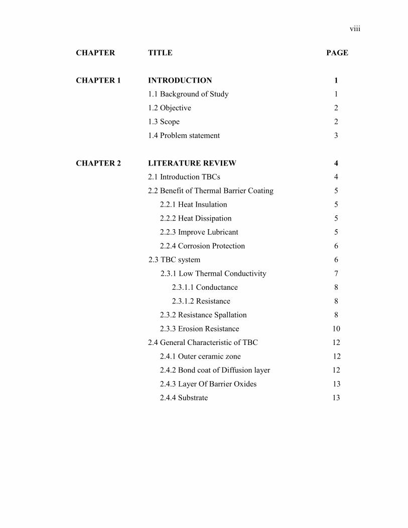
CHAPTER TITLE PAGE
CHAPTER 1 INTRODUCTION 1
1.1 Background of Study 1
1.2 Objective 2
1.3 Scope 2
1.4 Problem statement 3
CHAPTER 2 LITERATURE REVIEW 4
2.1 Introduction TBCs 4
2.2 Benefit of Thermal Barrier Coating 5
2.2.1 Heat Insulation 5
2.2.2 Heat Dissipation 5
2.2.3 Improve Lubricant 5
2.2.4 Corrosion Protection 6
2.3 TBC system 6
2.3.1 Low Thermal Conductivity 7
2.3.1.1 Conductance 8
2.3.1.2 Resistance 8
2.3.2 Resistance Spallation 8
2.3.3 Erosion Resistance 10
2.4 General Characteristic of TBC 12
2.4.1 Outer ceramic zone 12
2.4.2 Bond coat of Diffusion layer 12
2.4.3 Layer Of Barrier Oxides 13
2.4.4 Substrate 13

ix
CHAPTER TITLE PAGE
2.5 Heat Transfer Reaction 14
2.5.1 Radiation 14
2.5.2 Convection 15
2.5.3 Conduction 15
2.6 CES Edupack Analysis 16
2.7 Mechanism of turbocharger 17
2.8 Part of turbocharger 18
2.8.1 Turbine Housing 19
2.8.2 Wheel 19
2.8.3 Compressor Cover 20
2.8.4 Compressor Wheel (impeller) 20
2.8.5 Housing Turbocharger detail 21
CHAPTER 3 METHODOLOGY 23
3.1 Study procedure 25
3.2 Component Selection 25
3.3 Properties for TBCs 26
3.3.1 Low thermal conductivity 26
3.3.2 High resistance to spallation 26
3.3.3 Good erosion resistance 27
3.3.4 Morphology stability 28
3.4 CES Edu Pack Analysis 29
3.4.1 Material Properties Chart 29
3.5 Comparison Data 29
3.6 Analysis of Heat Transfer 30

x
CHAPTER TITLE PAGE
CHAPTER 4 RESULT AND ANALYSIS 31
4.1 CES Analysis 33
4.2 Thermal Conductivities Selected 34
4.3 Services Temperature Selected 35
4.4 Thermal Expansion Selected 36
4.5 Material Selected 37
4.6 The Overall heat transfer coefficient 38
4.6.1 Calculation for without insulation coating 40
4.6.2 Calculation with insulation coating 42
4.6.3Percentage of the reduction 44
CHAPTER 5 DISCUSSION 45
CHAPTER 6 CONCLUSION AND RECOMMENDATION 48
6.1 Conclusion 48
6.2 Recommendation 49
REFERENCES 50
APPENDIX 52

xi
LIST OF FIGURES
FIGURE TITLE PAGE
1.1 Adiabatic System 3
2.1 Schematic Plot Of The Expected Variation In Erosion
Behavior With Impact Angle 10
2.2 Microstructure Of Vacuum Plasma Sprayed Aluminium/
Alumina Composites 11
2.3 Schematic Of Coating Construction 13
2.4 Heat And Mass Transfer Mechanism Reaction Of Coating In
Deferent Layer 14
2.5 Three Level For Using The CES Edupact 17
2.6 Meghanisim Of Turbocharger 18
2.7 Turbine Housing 19
2.8 Wheel 20
2.9 Compressor Cover 20
2.10 Compressor Wheel 21
2.11 Housing Turbocharger 22
3.1 Study Procedure 23
3.2 Method To Accomplish This PSM 24

xii
FIGURE TITLE PAGE
3.3 Schematic of pore morphology 30
4.1 Thermal Conductivities vs. Melting Point 32
4.2 The Detail Material Shown From The CES Edupack 32
4.3 Graph For The Thermal Conductivities 34
4.4 Graph Of The Services Temperature 35
4.5 Graph Of The Thermal Expansion 36
4.6 Data Base From The CES Edupact About The Properties
Of Zirconia With Megnesia 37
4.7 Heat Transfer Thought The Wall 38
4.8 Cross Section Area For The Outlet Housing
Turbocharger 39
4.9 Cross Section Area For The Outlet Housing Turbocharger 41
4.10 Cross Section Area For The Outlet Housing Turbocharger With TBC
Flow of Heat Express By Formula 42
5.1 The Flow of Hot Gases From The Inside Housing Turbocharger
To The Atmosphere. 47
xiii
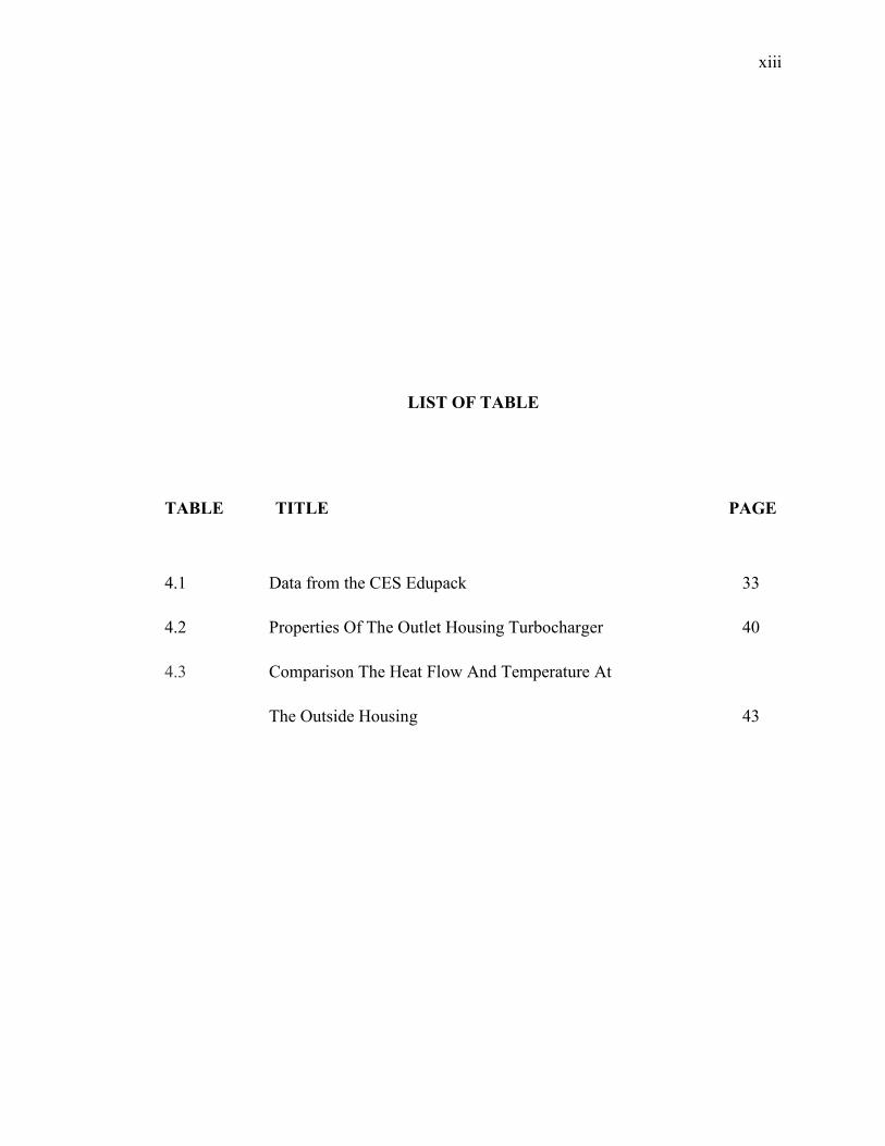
LIST OF TABLE
TABLE TITLE PAGE
4.1 Data from the CES Edupack 33
4.2 Properties Of The Outlet Housing Turbocharger 40
4.3 Comparison The Heat Flow And Temperature At
The Outside Housing 43

xiv
LIST OF SYMBOLS
ρ = Density
Cp = Constant Pressure
K = Thermal Conductivity
α = Thermal Diffusivity
ω = Specific Humidity
Q = Heat Flow
R = Resistance
= Deferent temperature outside and inside
V = Volume
T = Absolute Temperature
υυ = Specific volume
P = Pressure
µ = Dynamic viscosity, head coefficient, Degree of saturation
A = Area
xv
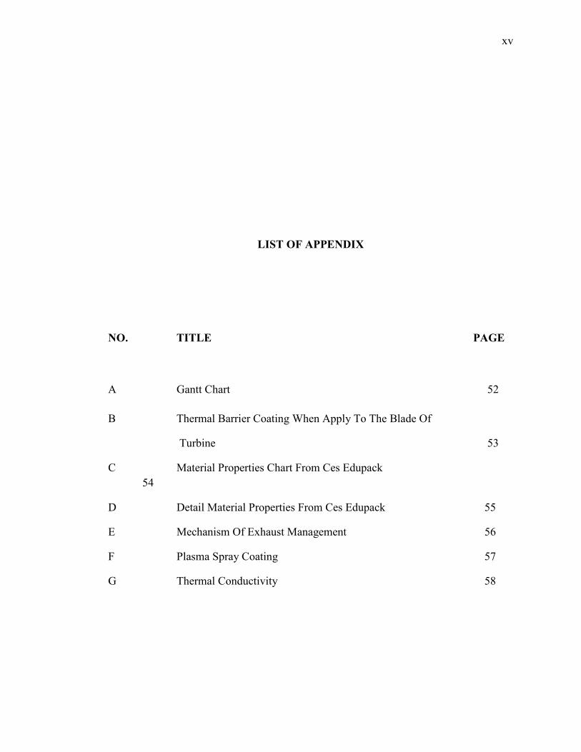
LIST OF APPENDIX
NO. TITLE PAGE
A Gantt Chart 52
B Thermal Barrier Coating When Apply To The Blade Of
Turbine 53
C Material Properties Chart From Ces Edupack 54
D Detail Material Properties From Ces Edupack 55
E Mechanism Of Exhaust Management 56
F Plasma Spray Coating 57
G Thermal Conductivity 58

1
CHAPTER 1
INTRODUCTION
1.1 Background of Study
Thermal barrier coatings are highly advanced material usually applied to metallic
surfaces, such as gas turbine or aero-engine parts, operating at elevated temperatures, as
a form of Exhaust Heat Management [13]. These coatings serve to insulate components
from large and prolonged heat loads by utilizing thermally insulating materials which
can sustain an appreciable temperature difference between the load bearing alloys and
the coating surface. In doing so, these coatings can allow for higher operating
temperatures while limiting the thermal exposure of structure.
Thermal barrier ceramic-coatings are becoming more common in automotive
applications. They are specifically designed to reduce heat loss from engine exhaust
system components including exhaust manifolds, turbocharger casings, exhaust headers,
downpipes and tailpipes. This process is also known as Exhaust Heat Management.
When used under-bonnet, these have the positive effect of reducing engine bay
temperatures, therefore lessening the intake temperature [13].
2
Thermal barrier coatings consist of four layers: the metal substrate, metallic bond coat, thermally grown oxide, and ceramic topcoat [13]. The ceramic is desirable for having very low conductivity while remaining stable at nominal operating temperatures typically seen in applications. Recent advancements in finding ceramic topcoat identified many novel ceramics (rare earth zirconates) having superior performance at temperatures above 1200 °C, however with inferior fracture toughness. This ceramic layer creates the largest thermal gradient of the TBC and keeps the lower layers at a lower temperature than the surface [5].
1.2 Objectives
The objective of this project is to determine the best material of thermal barrier
coatings (TBCs) for automotive component.
1.3 Scopes
The scopes of this project are:
Literature review on related topics.
Selected automotive component to coating.
To analyze the potential material of TBC applied for selected automotive
component by using CES Edu Pack.
Heat transfer analysis of selected material.
3
1.4 Problem Statement
When the part of engine is operate, the heat can be produced by the engine or
another automotive components. Normally the heat transformed to the environment as
waste, therefore it is possible to recover this heat loss thus increase efficiency of the
engine. It is in line with the 1st low Thermodynamic which mentions that ‘energy can
be neither created nor destroyed during a process, it can only change forms’. Therefore
it is predicted that if some potential component being insulated with thermal barrier
coating the heat loss from that component can be minimized, thus it will lead to higher
engine efficiency.
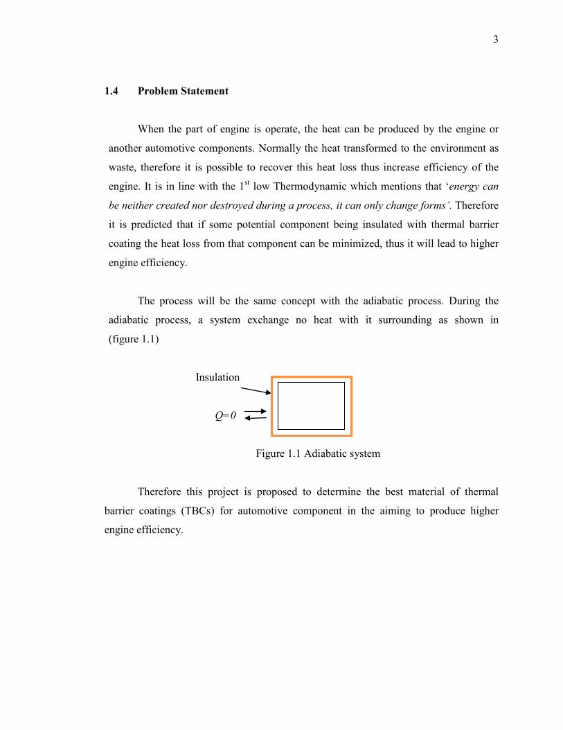
The process will be the same concept with the adiabatic process. During the
adiabatic process, a system exchange no heat with it surrounding as shown in
(figure 1.1)
Insulation
Q=0
Figure 1.1 Adiabatic system
Therefore this project is proposed to determine the best material of thermal
barrier coatings (TBCs) for automotive component in the aiming to produce higher
engine efficiency.
ADIABATIC
SYSTEM

4
CHAPTER 2
LITERATURE REVIEW
2.1 Introduction TBCs
Thermal barrier coatings are highly advanced material systems usually applied to
metallic surfaces, such as gas turbine or aero-engine parts, operating at elevated
temperatures, as a form of Exhaust Heat Management [5]. These coatings serve to
insulated components from large and prolonged heat loads by utilizing thermally
insulating materials which can sustain an appreciable temperature difference between
the load bearing alloys and the coating surface.
In turbine application, higher gas temperature will lead to higher turbine (Rapp,
1990). It is shown that the thermal barrier coating is important to shield metal part. It
was support by Emily A. Jarvis (1993) that “thermal barrier coatings of jet engine
turbines are critical for achieving powerful, fuel-efficient aircraft”.

5
2.2 Benefit of Thermal Barrier Coating
2.2.1 Heat Insulation
Metal failure due to overheat. Provide effective heat insulation to reduce
surrounding compartment heat which will help to [3]:
• Improve surrounding parts life
• Improve parts working efficiency and
performance
• Improve fuel economy due to HP &
Torque increase
2.2.2 Heat Dissipation
Heat generated by electronic devices and circuitry must be dissipated to
improve reliability and prevent premature failure. Metal failure due to overheat provide
effective heat dissipation to reduce the heat in the part which will help to[3]:
• Improve parts working efficiency and
performance
• Improve parts life
2.2.3 Improve Lubrication
Lubricating and maintaining such lubrication is critical to those friction parts (bearing);
• Improve lubrication
• Improve parts life
• Save energy
6
2.2.4 Corrosion Protection
Corrosion is the disintegration of an engineered material into its constituent
atoms due to chemical reactions with its surroundings. In the most common use of the
word, this means electrochemical oxidation of metals in reaction with an oxidant such
as oxygen. Metal parts failure due to corrosion attack. Provide corrosion resistance
insulation to[3]:
• Improve parts reliability
• Improve product quality ( metal melting
process )
• Save energy
2.3 TBC System
Modern TBC’s are required to not only limit heat transfer through the coating but
to also protect engine components from oxidation and hot corrosion. No single coating
Composition appears able to satisfy these multifunctional requirements. As a result, a
“Coating system” has evolved. Research in the last 20 years has led to a preferred
coating system consisting of three separate layers to achieve long term effectiveness in
the high temperature, oxidative and corrosive use environment for which they are
intended to function [5]:
1. Low thermal conductivity,
2. High resistance to spallation,
3. Good erosion resistance,
4. Phase stability and
5. Pore morphological stability

7
2.3.1 Low Thermal Conductivity
In physics, thermal conductivity, k, is the property of a material that indicates its
ability to conduct heat. It appears primarily in Fourier's Law for heat conduction.
Thermal conductivity is measured in watts per kelvin per metre (W·K−1·m−1). Multiplied
by a temperature difference (in kelvins, K) and an area (in square meters, m2), and
divided by a thickness (in meters, m) the thermal conductivity predicts the energy loss
(in watts, W) through a piece of material [7].
2.3.1.1 Conductance For general scientific use, thermal conductance is the quantity of heat that passes
in unit time through a plate of particular area and thickness when its opposite faces differ
in temperature by one Kelvin. For a plate of thermal conductivity k, area A and
thickness L this is kA/L, measured in W·K−1 (equivalent to: W/°C). Thermal conductivity
and conductance are analogous to electrical conductivity (A·m−1·V−1) and electrical
conductance (A·V−1) [7].
There is also a measure known as heat transfer coefficient: the quantity of heat
that passes in unit time through unit area of a plate of particular thickness when its
opposite faces differ in temperature by one Kelvin. The reciprocal is thermal insulance.
In summary [7]:

8
• thermal conductance = kA/L, measured in W·K−1
• thermal resistance = L/(kA), measured in K·W−1 (equivalent to: °C/W)
• heat transfer coefficient = k/L, measured in W·K−1·m−2
• thermal insulance = L/k, measured in K·m²·W−1.
• The heat transfer coefficient is also known as thermal admittance
2.3.1.2 Resistance
When thermal resistances occur in series, they are additive. Therefore when heat
flows through two components each with a resistance of 1 °C/W, the total resistance is 2
°C/W. A common engineering design problem involves the selection of an appropriate
sized heat sink for a given heat source. Working in units of thermal resistance greatly
simplifies the design calculation. The following formula can be used to estimate the
performance [7].
𝑅𝑅ℎ𝑠𝑠 = Δ𝑇𝑇𝑃𝑃𝑡𝑡ℎ
− 𝑅𝑅𝑠𝑠
2.3.2 Resistances to spallation
The spallation resistance, however, Is dependent on the mechanical properties of
all three layers .For example the TBC top layer must have a high in-plane compliance to
minimize the coefficient of thermal expansion (CTE) mismatch stress between the top
TBC layer and the underlying superalloy substrate[5].
(2.1)