Embed Size (px)
Citation preview
1. INTRODUCTION
The increasing frequencies of typhoons andlocalized torrential rainfall events are associated withsediment disasters involving debris flow (DF)[Marutani et al ., 2018] and large woody debris(LWD) [Gasser et al ., 2019]. In Japan, preventativefacilities have been built on the fluvial fans ; one suchstructure is like a steel open Sabo dam [Armanini etal ., 1991 ; Mizuyama et al ., 2008]. This damfacilitates normal sediment transport via appropriatespacing of the pipes [Mizuyama et al., 2010] andeffectively entraps DF and/or LWD [Piton & Rocking ,2016 a]. Moreover, the maintenance cost is low,because it is unnecessary to remove sediment.
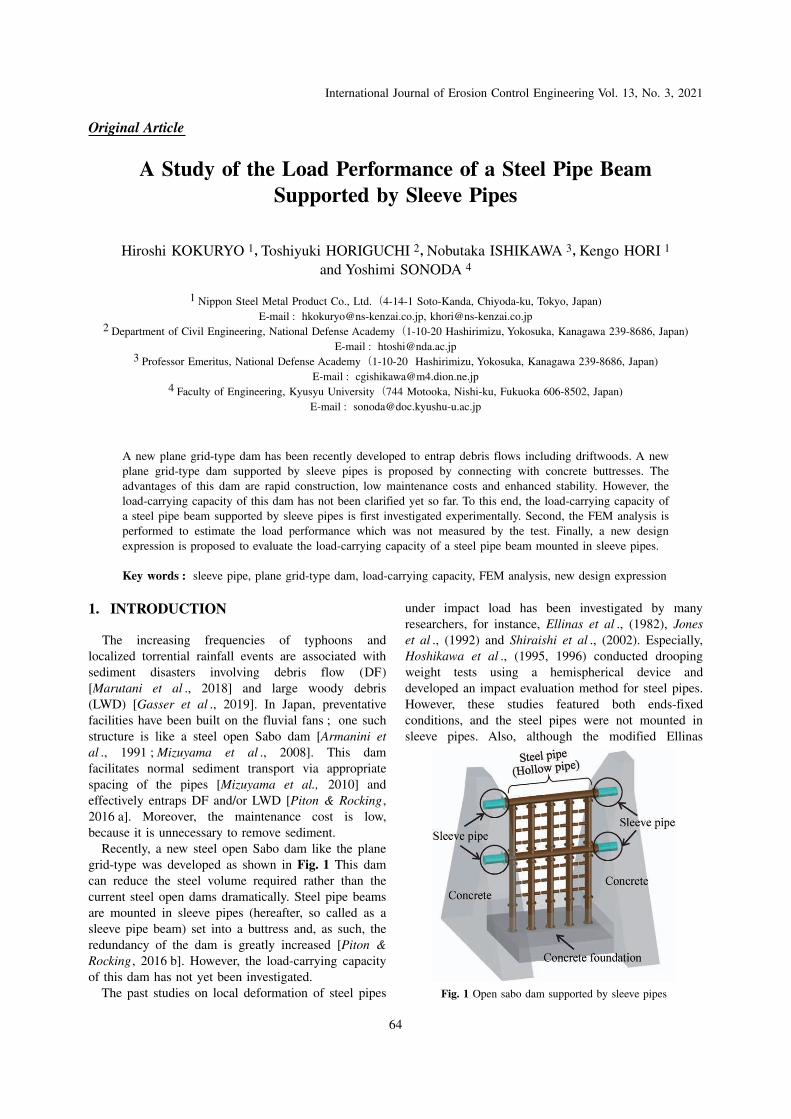
Recently, a new steel open Sabo dam like the planegrid-type was developed as shown in Fig. 1 This damcan reduce the steel volume required rather than thecurrent steel open dams dramatically. Steel pipe beamsare mounted in sleeve pipes (hereafter, so called as asleeve pipe beam) set into a buttress and, as such, theredundancy of the dam is greatly increased [Piton &Rocking , 2016 b]. However, the load-carrying capacityof this dam has not yet been investigated.
The past studies on local deformation of steel pipes
under impact load has been investigated by manyresearchers, for instance, Ellinas et al ., (1982), Joneset al ., (1992) and Shiraishi et al ., (2002). Especially,Hoshikawa et al ., (1995, 1996) conducted droopingweight tests using a hemispherical device anddeveloped an impact evaluation method for steel pipes.However, these studies featured both ends-fixedconditions, and the steel pipes were not mounted insleeve pipes. Also, although the modified Ellinas
Original Article
1 Nippon Steel Metal Product Co., Ltd.(4-14-1 Soto-Kanda, Chiyoda-ku, Tokyo, Japan)E-mail : [email protected], [email protected]
2 Department of Civil Engineering, National Defense Academy(1-10-20 Hashirimizu, Yokosuka, Kanagawa 239-8686, Japan)E-mail : [email protected]
3 Professor Emeritus, National Defense Academy(1-10-20 Hashirimizu, Yokosuka, Kanagawa 239-8686, Japan)E-mail : [email protected]
4 Faculty of Engineering, Kyusyu University(744 Motooka, Nishi-ku, Fukuoka 606-8502, Japan)E-mail : [email protected]
A new plane grid-type dam has been recently developed to entrap debris flows including driftwoods. A newplane grid-type dam supported by sleeve pipes is proposed by connecting with concrete buttresses. Theadvantages of this dam are rapid construction, low maintenance costs and enhanced stability. However, theload-carrying capacity of this dam has not been clarified yet so far. To this end, the load-carrying capacity ofa steel pipe beam supported by sleeve pipes is first investigated experimentally. Second, the FEM analysis isperformed to estimate the load performance which was not measured by the test. Finally, a new designexpression is proposed to evaluate the load-carrying capacity of a steel pipe beam mounted in sleeve pipes.
Key words : sleeve pipe, plane grid-type dam, load-carrying capacity, FEM analysis, new design expression
A Study of the Load Performance of a Steel Pipe BeamSupported by Sleeve Pipes
Hiroshi KOKURYO 1,Toshiyuki HORIGUCHI 2,Nobutaka ISHIKAWA 3,Kengo HORI 1
and Yoshimi SONODA 4
Fig. 1 Open sabo dam supported by sleeve pipes
International Journal of Erosion Control Engineering Vol. 13, No. 3, 2021
64

expression to measure the local deformation of a steelpipe beam under impact load has been used inJapanese design [NILIM , 2016 ; Sabo & LandslideTechnical Center, 2009], no study has exploredwhether this is appropriate for sleeve pipe beams.
In this study, the full-scale static load test of asleeve pipe beam is first performed to examine theload-carrying capacity [Kokuryo , et al ., 2018]. Second,a FEM analysis is executed to estimate the loadcarrying capacity of steel pipe beams [Sonoda , et al .,2016, Kokuryo , et al ., 2019]. Finally, a new designexpression for a sleeve pipe beam is proposed byapplying the modified Ellinas expression.
2. SLEEVE PIPES
The sleeve pipes connect the steel pipes with theconcrete foundation, improving the durability of theentire structure, because of an interaction effect.Initially, the sleeve pipes are set in concrete, and thesteel pipe is then slid into the sleeve pipes. Thus, theremust be some clearance between the sleeve and thesteel pipe as shown in Fig. 2, which may becomedetached after a disaster. If the steel pipe is simplyembedded in concrete, the insertion length of the pipeis larger than the outside diameter ; it is in fact morethan twice the diameter ( ) (e.g ., =406.4 mm×2=812.8 mm≧2 ). The relationship between thedrawing force ( ) and the drawing resistance ( )described below refers to Fig. 3.
2.1Maximum load of the steel pipe beam at both-fixed-ends
When the steel pipe is assumed to be a both-ends-fixed beam, the maximum load ( ) is computed bythe collapse mechanism neglecting the localdeformation at the loading point as follows :
(1a)
(1b)
(1c)
where : the plastic moment, : the yield stress
of the steel pipe, : the span length ( =3,500 mm),: the plastic section modulus, : thickness.
2.2 Drawing force of the sleeve pipe beamThe drawing force of the steel pipe ( ) is :
(2a)
(2b)
(2c)
(2d)
where : the angle after local deformation of a steelpipe, : the inclination of a steel pipe inserted into asleeve pipe, : the clearance between the sleeve andsteel pipes, and : the allowable plastic rotationangle of the steel pipe [STC , 2009].
2.3 Resistance force inside a sleeve pipe beamThe resistance force inside a sleeve pipe beam ( )
is :
(3)
where : the friction coefficient between the steelpipes (0.23 in Japanese design [STC , 2009]), and :the surface friction resistance (here, assumed to be 1/4for steel pipe). Table 1 lists the test case andverification.
Fig. 3 Sleeve pipe beam
Fig. 2 Cross-section of a sleeve pipe beam
International Journal of Erosion Control Engineering Vol. 13, No. 3, 2021
65

3. EXPERIMENTAL SETUP
3.1 Static load testA test piece was manufactured ; the ends of a steel
pipes were inserted into sleeve pipes embedded inconcrete on both sides, as shown in Fig. 4. Then, ahemispherical load was statically applied to the centerof the steel pipe using a static loading machine. Fig. 5shows a panoramic view of the static test device and aclose-up of the loading position. The measured itemswere the load at the center point, the displacements,and the strains. The load was measured by a load cellattached to the upper part of the load body, anddisplacements were measured at four points on thesteel pipe. The strains were measured at four pointsclose to the center of the steel pipe, and at anotherfour points in the sleeve pipe to observe horizontalmovement of the steel pipe beam, as shown in Fig. 4.
3.2 Test pipesThe two steel pipes (#1 and #2) used in the test are
carbon steel employed for general structures (JIS G3444). They are the same diameter ( =406.4 mm), thesame span length ( =3,500 mm) with two differentthicknesses ( =7.9 mm and 12.7 mm), and the insertionlength ( =1,000 mm), as shown in Fig.4 and Table 2.
In practice, the pipe diameter ratios (diameter/thickness) of 30―60 are used in a steel open dam ;The pipes used in the test had ratios of 51 and 32. Thesleeve pipe of 457.2 mm in diameter, thus larger thanthe steel pipe, and 9.0 mm in thickness, was employed.The sleeve pipes and the concrete foundation are inclose contact, while clearance is required between thesleeve pipes and the inserted steel pipe (16.4 mm oneither side in the present case). The concretefoundation was standard, as shown in Table 3.
Table 1 Test case
Fig. 4 Experimental setup and settings (unit : mm)
Fig. 5 Static load test
International Journal of Erosion Control Engineering Vol. 13, No. 3, 2021
66

4. EXPERIMENTAL RESULTS
4.1 Case1(D=406.4mm, t=7.9mm)Fig. 6 (a), (b) and (c) show the deformation profiles
of the pipe beam at the loads of 100, 200 and 250 kN,respectively. Fig. 6 (a) shows beam did not deformradically at 100 kN. Fig. 6 (b) shows the deformationprofile of the pipe at 200 kN. Fig. 6 (c) shows themoment at which the ratio of local deformation topipe diameter (it is termed / ) attained 40%, and250 N, which is the repair limit state which isimportant in terms of definition of repair of pipe [STC,2009].
Fig. 7 shows the relationship between the load anddeformation at the centre of steel pipe beam, in which
the displacements of the upper- and under-surfaces atthe center are shown. Therefore, the local deformationis depicted as the difference ( = - ) betweenupper-surface displacement ( ) and the under-surfacedisplacement ( ).
Fig. 8 shows the relationship between the load anddeformation of the ends of the steel pipe, in which theunder-surface displacements at the center and at theend are shown. Therefore, the real beam displacementat the center is given as the subtraction ( = - ) ofthe end settlement ( ) from the under-surfacedisplacement ( ). The real beam displacement ( )was also compared with the theoretical deflectionwhich is calculated by the simply supported steel pipeas follows :
Table 2 Specifications of the steel pipe
Table 3 Concrete foundation
Fig. 6 Deformation profiles at each loading (Case 1)
Fig. 7 Relationship between load and displacement(Case1:Local deformation)
Fig. 8 Relationship between load and displacement(Case1:Real beam displacement)
International Journal of Erosion Control Engineering Vol. 13, No. 3, 2021
67

(4)
where : Young’s modulus and : the sectionalsecondary moment of the steel pipe.
Table 4 compares the results of the sleeve pipebeam with the simply supported beam (i. e., thetheoretical deflections ) at initial stage of loading.The displacement of the under-surface at the center( ) is larger than the theoretical value. However,settlement ( ) occurs at the end of the steel pipecommencing at initial loading, and to approximately150 kN, the real beam displacement ( = - ) is ingood agreement with the theoretical deflection of asimply supported beam. Therefore, during initialloading, both the sleeve pipe and simply supportedbeams exhibit very similar deformation behavior.However, when the load attains 190―200 kN, the onlydisplacement increases. Furthermore, as the increase ofload, the displacement also increased, and themaximum load was approximately 750 kN.
An examination of the load-carrying capacity ofsteel pipes supported in different ways revealed thatthe maximum load of the sleeve pipe beam (750kN) lay between the full plastic loads (collapse loads)of the simply supported beam ( )(456 kN) and theboth-ends-fixed beam ( )(912 kN), but closer to thelatter value. The collapse loads of the simplysupported and both-end-fixed beams were calculatedusing the following equations, respectively.
(5)
(6)
These results imply that the support afforded by thesleeve pipe at initial loading was close to that of asimply supported beam, but, as the load increased, theload-carrying capacity became closer to that of a both-ends-fixed beam. Therefore, the maximum load of thesleeve pipe beam (approximately 750 kN), ,corresponds to approximately 82% of the full plasticload (912 kN) of a both-ends-fixed beam, . Thismay be caused by the reason that the both-ends ofsleeve pipe beam may become a semi-fixed supportincluding a little rotation which is not complete rigid.
4.2 Case2(D=406.4mm, t=12.7mm)Fig. 9 shows the condition of the test piece when
loads of 200, 600 and 900 kN (deformation rate 40%)were applied, respectively. As with Case 1, the pipedeformed as the load was applied, but the detailedresult is different. In Case 1, because of the thinnerthickness of the pipe ( / =51), the deformation wasmore intense than in Case 2. Furthermore, in Case 2,the deformation was small even with an equivalentload because of the thicker thickness ( / =32).
Figs. 10 and 11 indicate the relationship betweenthe load and displacement at the center of the steelpipe and the theoretical deflections calculated usingEq. (4), respectively. In Case 2, given the thickness ofthe steel pipe, the load was raised, but the experimentceased at approximately 1,200 kN due to the limitationof the loading device. The displacement at the centerof the steel pipe during the test ( = - ) is shown
Table 4 Comparison of the test and theoretical displacements at initial stage of loading (Case1)
Fig. 9 Deformation profiles at each loading (Case 2)
International Journal of Erosion Control Engineering Vol. 13, No. 3, 2021
68

in Table 5. Up to 400 kN, the deformation was verysimilar to that of a simply supported beam.
Moreover, the relationship between the load anddisplacement within the applicable load range wassimilar in Case 1. In other words, when the load wasincreased to about 500 kN, the displacement alsoincreased, but when the load approached 500―550 kN,the displacement continued to increase only because ofsliding. Therefore, in Case 2, displacement at initialloading, which ignores displacement of the end of thepipe, and also exhibited behavior similar to that of asimply supported beam. However, sliding exerted a
stronger influence.As for Case 2, the full plastic load of the simply
supported beam and the both-ends-fixed beam,and , were calculated using Eq. (5) and (6) andwere 956 and 1,912 kN, respectively. Thus, within theload range of the test (approximately 1,200 kN), theload-carrying capacity was superior to that of a simplysupported beam.
4.3 Sliding amount of a sleeve pipeFig. 12 shows the horizontal movement of the steel
pipe in Case 1. When the load increased, sliding
Fig. 11 Relationship between load and displacement(Case2:Real beam displacement)
Fig. 10 Relationship between load and displacement(Case2:Local deformation)
Table 5 Comparison of the test and theoretical displacements at initial stage of loading (Case2)
Fig. 12 Sliding amount of sleeve pipe beam
International Journal of Erosion Control Engineering Vol. 13, No. 3, 2021
69

increased simultaneously. When approximately 200 kN[Fig. 12(a)] was applied, displacement increased ; thepipe slid 20 mm. As the load increased, displacementattained approximately 50 mm at the maximum load of750 kN [Fig. 12(b)]. However, this is only 5.0 % ofthe insertion length into the sleeve pipe ( =1,000mm) in length, because 2.8 % of the half-span lengthof the steel pipe ( /2) is 1,750 mm. Therefore, it isconsidered that the effect of sliding amount on thedeformation of sleeve pipe beam is small.
However, when in design sleeve pipes that mustwithstand boulder collisions, it is necessary to considersteel pipe deformation and sliding caused by theclearance between the steel and sleeve pipes. Finally,these results suggest that this requirement can be metusing the next new design expression in which asleeve pipe beam should be treated as semi-fixed ends,not complete-fixed ends.
5. FEM ANALYSIS
The objective of this analysis is to reproduce(simulate) the load test to verify the applicability ofthe FEM analysis up to the maximum load in Case 1,as well as the one of Case 2, which could not bemeasured in the test.
5.1 Analytical modelThe analysis was carried out by using the non-linear
analysis code MSC Marc (1971) based on the Finite
Element Method (FEM). Considering the symmetry ofthe test piece in the load test, the model was used the1/4 scale that is same to experiment model, whichmeans the span length of 1/2 and the diameter of 1/2,as shown in Fig. 13.
Regarding the type of analysis elements, the steelpipe members (between beam and sleeve), the concretebody, and the load body were defined as a shellelement, a solid element, and a rigid body, respectively.Also, as boundary conditions, the base of the concretebody was completely fixed, the concrete body andsleeve pipes were completely fixed to each other, and acoefficient of friction of 0.3 was set, considering theinfluence of friction between the contact surface of thesteel pipe beam and sleeve pipe.
5.2 Material properties used in the analysisThe material properties used in the analysis are
shown in Table 6. The Poisson’s ratios of the pipe andconcrete material were set to 0.3 and 0.194, and thespecific weights to 77.0 kN/m3 and 22.5 kN/m3,respectively. For the stress-strain relationships of pipematerials STK 400 and STK 490, the true stress-truestrain relationships were used.
5.3 Simulation resultsFig. 14(a) and (b) show the simulation results of
Case 1 and Case 2 by FEM analysis, respectively.A comparison of the analysis and the test results
shows that the FEM analysis simulated accurately to
Fig. 13 Analytical model
Table 6 Material properties of steel pipe and concrete
International Journal of Erosion Control Engineering Vol. 13, No. 3, 2021
70

the test results in both cases, from the behavior at theinitial stage of loading including the influence ofsliding to the displacement increase as the load isincreased. It was confirmed the computational resultsare almost good agreement with the test results.
Table 7 shows a comparison of the maximum loadsof test and analysis values. Although the maximumload of Case 2 has not obtained by the test due to thelimitation of loading device, FEM analysis was able toobtain as 1,821 kN which is almost near the fixedbeam. The collapse loads of the simply supportedbeam and the both-ends-fixed beam, calculated withEq. (5) and (6), are also listed.
6. Proposal of new design formula for sleevepipe beam
It is proposed that a new design formula for a steelpipe beam mounted in sleeve pipe (hereafter, it is
called as a sleeve pipe beam) is expressed by applyingthe modified Ellinas expression, in which both fixedends are changed into the semi-fixed ends, as shown inFig. 15(a). Therefore, Table 8 shows the bendingmoment diagram, the equation of maximum load andits value of the sleeve pipe beam compare with thoseof the simply supported beam and the both-ends-fixedbeam.
6.1 New design formula of sleeve pipe beam6.1.1 Load corresponding to local deformation
The load ( ) corresponding to local deformation ofa sleeve pipe beam, as the same as a steel pipe can bedetermined by referring to the ‘modified Ellinasexpression [Hoshikawa , et al. 1995, Ishikawa , 2009]as follows.
(6a)
Fig. 14 FEM analysis results comparing with test result
Table 7 Comparison of the maximum loads by test and analysis
Fig. 15 Deformed steel pipe shape and collapse mechanism of sleeve pipe beam
International Journal of Erosion Control Engineering Vol. 13, No. 3, 2021
71

(6b)
where : the boulder diameter and : thedynamic yield stress intensity of steel pipe ( =1.0-1.2 ).6.1.2 Collapse load of sleeve pipe beam (PC)
If both ends of the sleeve pipe beam are assumed assemi-fixed, the collapse load can be obtained by thecollapse mechanism of sleeve pipe beam in Fig. 15(a).
(7a)
(7b)
(7c)
(7d)
(7e)
(7f)
Herein, when the plastic moment is calculated, it isassumed that the cross-section of the steel pipe iscircular before deformation and is elliptical afterdeformation, as shown in Fig. 15(b).Where, : the span length, : the plastic momentof the semi-fixed end, : the plastic moment of thecenter point, : the largest radius of the ellipse, :the shortest radius of the ellipse, : semi-fixed factorwhich is determined as the ratio of the value by FEManalysis with the one of both-ends-fixed beam, =0.87 and 0.95 in Cases 1 and 2.
6.1.3 Maximum local deformation of sleeve pipebeam
The maximum local deformation of steel pipe ( )is attained when the load ( ) and the collapse load ofthe sleeve pipe beam ( ) are equal, and is found as :
( 8 )
The maximum deformation ( ) is computed byassuming values for “ ” and iterating until the valueconverges.
6.2 Energy absorption6.2.1 Energy absorption by local deformation
The energy absorption ( ) prior to the maximumlocal deformation of the steel pipe ( ) is expressedas :
(9)
6.2.2 Energy absorption by plastic deformation ofsleeve pipe beam
The energy absorption by plastic deformation of asleeve pipe beam is computed as follows :
(10a)
(10b)
(10c)
where : the collapse load of the sleeve pipe beam,: the allowable plastic deformation, : the
allowable plastic rotation angle (STC, 2009).
Table 8 Comparison of the maximum loads by different supported beams
International Journal of Erosion Control Engineering Vol. 13, No. 3, 2021
72

6.3 Verification of new design formulaFig. 16 shows the relationships between load and
deformation of Case 1 and 2 comparing the newdesign expression (hereafter, design) with test andanalysis results, respectively. The energy absorptions ofdesign, test and analysis were illustrated by the areasof load-deformation curves as shown in Fig. 16(a)―(f),respectively.
These results are summarized in Table 9. The
energy absorptions by test (168 kJ) and analysis (210kJ) in Case 1 were about 1.3~1.7-fold higher than theone by the design (125 kJ), respectively.
In Case 2, the energy absorbed by the analysis (773kJ) was 2.8-fold larger than that of the design (270 kJ).The results confirm that the design remainsconservative when the new design expression isadopted in the design of the sleeve pipe beam.
Fig. 16 Comparison of energy absorptions between design, test, and analysis
International Journal of Erosion Control Engineering Vol. 13, No. 3, 2021
73

7. DISCUSSION
7.1 Maintenance of new plane grid-type damA steel open dam allows constant transport of
normal amounts of sediment, and efficiently traps DFand/or LWD [Armanini et al ., 1991].
The proposed new plane grid-type dam with sleevepipe dam does not require a large area. Also, this newdam can trap DF and/or WDF from small, inactive,and usually dry catchments [NILIM , 2016 ; STC ,2009]. It is possible to construct the new grid-typedam even in geographically challenging regions.
The maintenance cost of the new plane grid-typedam will be decreased. If the sleeve pipe beam isdamaged after DF, the pipe can be easily replaced. Ifthere is no damage, it is easy to detach the steel pipeto remove DF and WD. Thus, this dam life isprolonged ; Repair and reinforcement of this dam arevery simple.
7.2 Problems with the new design formulaThe scale of DF is recently becoming large and
heavy due to the abnormal weather. The impulsiveloads of debris flows have been so far examined by[Ancey et al ., 2015 ; Faug , 2015 ; Song et al ., 2015 ;Hübl et al ., 2015 ; Poudyal et al ., 2019]. The debrisflow fluid force [Daido et al ., 1994] and the bouldercollision load [Mizuyama et al ., 1979] have beenevaluated. However, impulsive and/or impact loadperformance evaluations for a sleeve pipe beam havenot been addressed. Therefore, it is needed toinvestigate the dynamic effects of a sleeve pipe beam.The limits of application of new design formula for asleeve pipe beam should be explored by impact test oranalysis in the near future.
8. CONCLUSIONS
This study investigated the load-displacementrelations of steel pipe beams supported by sleeve pipethrough a static load test and FEM simulation. Finally,a new design expression was proposed. The following
conclusions were drawn from this study.(1) It was found that the maximum load of the sleevepipe beam was nearly equal to the one of both-ends-fixed beam from the viewpoint of the load-carryingcapacity.(2) At initial loading, the displacement at the centerexhibited deformation behavior similar to that of asimply supported beam.(3) At the halfway stage of loading, the onlyhorizontal deformation noted was caused by theclearance between the steel pipe and the sleeve pipes.Then, as the load increased, the sleeve pipe beambecame similar to those of a both-ends-fixed beam.(4) It was clarified that the maximum load (1821 kN)of the # 2 sleeve pipe beam was estimated by the FEManalysis, although it was not obtained by the test.(5) A new design formula was proposed for a sleevepipe beam by introducing the semi-fixed ends into themodified Ellinas expression.(6) The dynamic problems (such as boulder collisionsin debris flows) for a sleeve pipe beam should beinvestigated in the future.
REFERENCESAncey, C., Bain, V. (2015) : Dynamics of glide avalanches and
snow gliding, Reviews of Geophysics, Vol. 53, No. 3, pp.745―784.
Armanini, A., Dellagiacoma F. and Ferrari L. (1991) : From thecheck dam to the development of functional check dams,Fluvial Hydraulics of Mountain Regions , pp. 332―344.
Daido, A., Yoshizumi, M. and Nakajima, K. (1994) : Impactforce of mud-debris flows acting on structure. Proceedingsof Hydraulic Engineering , Vol. 38, pp. 557―562.
Ellinas, C. P., Walker, A. C. (1982) : Damage on offshoretubular bracing members, IABSE Reports, Vol. 42, pp. 253―261.
Faug, T. (2015) : Macroscopic force experienced by extendedobjects in granular flows over a very broad Froude-numberrange, European Physical Journal E , Vol. 38, No. 24, pp. 1―10.
Gasser, E., Schwarz, M., Simon, A., Perona, P., Phillips, C.,Hübl, J. and Dorren, L. (2019) : A review of modeling the
Table 9 Comparison of energy absorption by test, analysis and design
International Journal of Erosion Control Engineering Vol. 13, No. 3, 2021
74

Received : 22 July 2019Accepted : 19 May 2020
effects of vegetation on large wood recruitment processes inmountain catchments, Earth-Science Reviews, Vol. 194, pp.350―373.
Hiramatsu, S., Fukuyama, T., Yamada, T., Ohsaka, O., Nakatani,K., Matsumoto, N., Fujimura, N., Kato, N., Shimada, T.,Kubo, T, Matsuo, S., Nishio, Y. and Yoshino, H. (2014) :Debris flow disaster of July 9th, 2014, in Nagiso, Nagano,Journal of the Japan Society of Erosion ControlEngineering , Vol. 67, No. 4, pp. 36―48. (in Japanese)
Hoshikawa, T., Ishikawa, N., Hikosaka, H. and Abe, S.(1995) :The impact response displacement of steel pipe fixed beamsconsidering local deformation and strain velocity effect,Proceedings of JSCE , No. 513/I―31, pp. 101―115, 1995. 4(in Japanese).
Hoshikawa, T., Ishikawa, N., Hikosaka, H. and Abe, S.(1994) :The impact response displacement of steel pipe fixed beamsthrough the drop off of a hemispherical weight, Journal ofStructural Engineering , Vol. 40 A, pp. 1543―1554 (inJapanese).
Hübl, J., Nagl, G., Suda, J. and Rudolf-Malklau, F. (2017) :Standardized stress model for design of torrential barrierunder impact by debris flow (according to Austrian StandardRegulation 24801), International Journal of the JapanSociety of Erosion Control Engineering , Vol. 10, No. 1, pp.47―55.
Ishikawa, N. (2009) : Design manual for Sabo dams with ahollow pipe structure, Design Handbook of Steel SaboStructures, 2009 Edition, Sabo & Landslide TechnicalCenter, Steel Sabo Structure Committee, pp. 219―224 (inJapanese).
Jones, N., Shen, WQ. (1992) : A theoretical study of lateralimpact of fully clamped pipelines, Proc. of the Institution ofMechanical Engineers , Vol. 206 (E), pp. 129―146.
Kokuryo, H., Hori, K., Horiguchi, T. and Ishikawa, N.(2018) :An experimental study on the load carrying capacity of steelpipe beam supported by covered pipes, Japanese Society ofSteel Construction, Vo. 25, No. 100, pp. 57―71, (inJapanese)
Kokuryo, H., Horiguchi, T., Ishikawa, N. and Shima, J.(2018) :Prevention and mitigation of debris flow disaster by steelopen barrier in small-scale torrent, Proc. of the 7 thInternational Conference on Protection of Structures againstHazards, pp. 45―59.
Kokuryo, H., Horiguchi,T., Ishikawa, N., Sonoda, Y. and Hori,K. (2019) : Load carrying capacity of steel pipe beamsupported by covered pipe, Proc. of the 12 th PacificStructural Steel Conference, Tokyo, Japan, Nov.
Marutani, T. et. al . (2017) : Sediment-related disasters by aheavy rainfall in the northern part of Kyushu-Island, Japan,July 2017, Journal of the Japan Society of Erosion CivilEngineer, Vol. 70, No. 4, pp. 31―42.
Mizuyama, T. (1979) : Computational method and someconsideration on impulsive force of debris flow acting onSabo dam. Journal of the Japan Society of Erosion Control
Engineering , Vol. 112, pp. 40―43.Mizuyama, T. (2008) : Structural countermeasures for debris
flow disasters, International Journal of Erosion Control ofEngineering, Vol. 1, No. 2, pp. 38―43.
Mizuyama, T. (2010) : Recent developments in Sabo technologyin Japan, International Journal of Erosion ControlEngineering , Vol. 3, No. 1, pp. 1―3.
MSC Marc (1971) : MSC software, retrieved from https : //www.mscsoftware.com/product/marc
National Institute for Land, Infrastructure Management,Ministry of Land, Infrastructure, Transport and Tourism,Japan (2016) : Manual of technical standard for designingSabo facilities against debris flow and driftwood, No. 905.(in Japanese)
Piton, G., Rocking, A. (2016 a) : Design of sediment trap withopen check dams, II : woody debris, Journal of HydraulicEngineering, ASCE , Vol. 142, No. 2, pp. 1―13.
Piton, G., Rocking, A. (2016 b) : Design of sediment traps withopen check dams I : Hydraulic and deposition processes,Journal of Hydraulic Engineering, ASCE , Vol. 142, No. 2,pp. 1―16.
Poudyal, S., Choi, C., E., Song, D., Zhou, G., G., D., Yune, C.,Y., Cui, Y., Leonardi, A., Busslinger, M., Wendeler, C.,Piton, G., Moase, E. and Strouth, A. (2019) : Review of themechanisms of debris-flow impact against barriers, 7 thInternational Conference on Debris-Flow Hazards Mitigation,pp. 1―8.
Sabo & Landslide Technical Center, Steel Sabo StructureCommittee, (2009) : Design Handbook of Steel SaboStructures (in Japanese).
Shima, J., Matsuzawa, R., Yamaguchi, M., Takeda, I., Ishikawa,N. and Mizuyama, T. (2017) : Problems and impact analysisof the current design method for steel open Sabo damsimpacted by rocks, Journal of the Japan Society of ErosionControl Engineering , Vol. 70, No. 1, pp. 54―59. (inJapanese)
Shiraishi, H., Kajita, Y., Katsuki, S., Ishikawa, N., Matsumura,K. and Shima, J. (2002) : Residual strength evaluationexperiment of hollow steel pipes damaged by a rockcollision, Journal of Structural Engineering, Vol. 48 A, pp.1505―1512. (in Japanese)
Song, D., Ng, C. W. W., Choi, C. E., Kwan, J. S. H. and Koo,R. C. H. (2017) : Influence of debris flow solid fraction onrigid barrier impact, Canadian Geotechnical Journal , Vol.54, No. 10, pp. 1421―1434.
Sonoda, Y., Tsuchiya, Y., Tamai, H. and Shima, J.(2016) : Afundamental study on the load carrying capacity of steelframe check dam, Japan Society of Civil Engineer, Journalof Structural Engineering, A, Vol. 62, pp. 1019―1030. (inJapanese)
International Journal of Erosion Control Engineering Vol. 13, No. 3, 2021
75