Embed Size (px)
Citation preview
1
A Study for a Space-Based Passive Multi-Channel SAR Matteo Sedehi, Diego Cristallini, Fabiola Colone, Marta Bucciarelli, Pierfrancesco Lombardo
Dept. INFOCOM- University of Rome “La Sapienza”, Via Eudossiana 18, 00184 Rome, Italy
Ph. +39-06-44585472, Fax: +39-06-4873300 sedehi, cristallini, fabiola.colone, mbucciarelli, [email protected]
Abstract—This paper deals with the potentialities obtained by splitting the passive antenna of a space-based bistatic SAR into multiple sub-apertures. A preliminary analysis is performed in order to identify the main orbital and system design parameters for a satellite equipped with a multi-channel passive radar sensor. The effectiveness of the resulting bistatic system is investigated paying particular attention to the assessment of the achievable MTI, Enhanced Imaging and ECCM capabilities. In particular the conceived system is shown to allow: (i) clutter cancellation and detection of slowly moving ground targets for surveillance purpose, (ii) relocation of moving targets in high resolution SAR images, (iii) increased SAR imaging capabilities in terms of extended swath and/or increased azimuth resolution, (iv) protection of the SAR sensor from E.M. interferences.
TABLE OF CONTENTS
1. INTRODUCTION ..................................................... 1 2. BISTATIC ORBITAL CONFIGURATIONS................. 2 3. RECEIVING MULTI-CHANNEL SYSTEM ................ 3 4. MTI APPLICATIONS.............................................. 4 5. ENHANCED IMAGING ............................................ 7 6. ELECTRONIC COUNTER COUNTER MEASURES..10 7. CONCLUSIONS .....................................................15 REFERENCES...........................................................16
1. INTRODUCTION
Several missions for Earth observation and monitoring are currently in progress based on a constellation of satellites carrying a SAR sensor. An important example is given by the Italian COSMO-SkyMed, developed by Alenia Spazio under contract by the Italian Space Agency (ASI) and the Italian Ministry of Defence. Four satellites will allow both wide area mapping at low resolution in ScanSAR mode and high resolution imaging in Spotlight SAR mode at X band of the Mediterranean latitudes with repetition times of a few hours.
The potentialities obtained by augmenting the COSMO/SkyMed constellation with single-channel receiving-only sensor, capable to coherently operate with the main system without requiring its design modification, has been investigated by D’Errico and Moccia [1]. As well known, bistatic radar systems offer several advantages over their monostatic counterparts, including the capability for enhanced target radar cross section, avoidance of eclipsing, and reduced vulnerability to E.M. interferences. However,
the increased complexity of the resulting system yields a number of additional constraints concerning orbital, architectural and technological aspects.
On the other side a monostatic multi-channel sensor has been proposed by Lombardo et al. ([2]-[4]) for COSMO/SkyMed second generation SAR, obtained by splitting the active phased array antenna in multiple sub-apertures. The modified sensor was demonstrated to allow a number of extra applications, including: (i) clutter cancellation and detection of slowly moving ground targets, (ii) sea current/wave monitoring by along-track interferometry, (iii) exact positioning of strong moving targets in SAR images, and (iv) fully polarimetric images. However the proposed monostatic multi-channel system requires proper design modifications with respect to the first generation sensor which have a significant impact on costs and development terms.
In this paper a preliminary bistatic mission analysis is performed aiming at identifying the main design parameters for a satellite equipped with a multi-channel passive sensor operating with a phased array antenna split in multiple sub-apertures connected to multiple receiving channels. The conceived system allows the largest reuse of what has already been developed for the SAR of COSMO-SkyMed of 1st generation, which would play the role of the transmitter in the resulting bistatic radar, thus yielding reduced development costs. Moreover, the passive multi-channel sensor is expected to have similar potentialities with respect to its monostatic version while yielding a number of extra advantages related to the bistatic geometry. In particular the proposed sensor is expected to allow:
(1) Clutter cancellation and detection of slowly moving ground targets for surveillance by applying space-time adaptive processing (STAP) techniques to the multi-channel set of collected radar data;
(2) Exact positioning and imaging of strong moving targets in the high resolution SAR images by using a spatial discrimination capability to compensate for the erroneous displacements due to the motion component;
(3) Increased SAR imaging capabilities in terms of extended swath and/or increased azimuth resolution;
(4) Protection of the SAR sensor from E.M. interferences by implementing antenna-based Electronic Counter CounterMeasures (ECCM).
2
In this paper, different bistatic formations are investigated. Moreover, the main sensor design parameters and constraints are identified (antenna dimensions, numbers of receiving channels, beam scanning angles, PRF) together with a consistent way to split the available antenna aperture to obtain a high performing multi-channel radar [2]-[4]. The effectiveness of the conceived bistatic system in the described applications is investigated by means of simulations, and different identified solutions are compared in terms of achievable performance.
2. BISTATIC ORBITAL CONFIGURATIONS
The performed mission analysis aims to identify the possible solutions for a bistatic mission, considering that the transmitter antenna platform is expected to fly on the orbit selected for the COSMO/SkyMed mission. The main parameter in this case is the bistatic angle, capable to really differentiate performance of the radar system. Two different considerations arise:
(1) A large bistatic angle has a meaningful influence on the target radar cross section, eclipsing, and vulnerability to E.M. interferences;
(2) Mission flexibility, namely the capability of the passive satellite to work together with the transmitting system without requiring any modification to its mission, is inversely proportional to the bistatic angle.
As a consequence, two different bistatic configurations are considered:
(1) Long-baseline configuration, characterized by a large bistatic angle aiming at enhancing the bistatic geometry advantages;
(2) Interferometric configuration, characterized by small antenna separation, which is expected to allow an easier system parameters design.
Long-Baseline Configuration
The possibility to work with a large separation between the two platforms could be of great interest for a number of applications as showed by D’Errico and Moccia [1].
Considering that the COSMO/SkyMed radar varies its off-nadir angle by exploiting its electronic steering capabilities, the passive satellite orbit is designed in order to guarantee the acquisition of bistatic radar data for the largest range of latitudes [5]. The orbit is designed with the same semi-major axis, eccentricity, and inclination (i) of the primary mission, to guarantee the same precession rates (ascending node and perigee) for both. Moreover, both orbits are frozen by selecting the same argument of perigee.
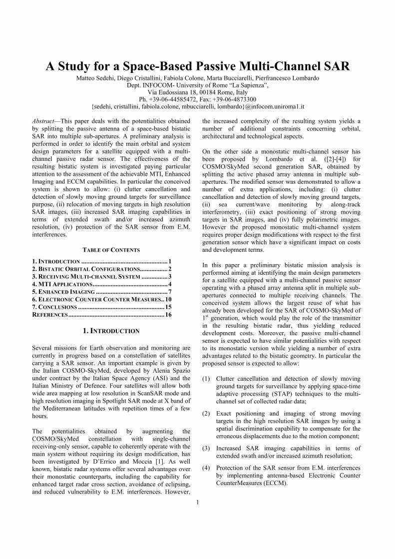
The two main parameters for configuration selection are the ascending node right ascensions offset (∆Ω) and the mean anomalies difference (∆M) at the times of the passages on the ascending node (see Figure 1). As far as the times of the passages on the ascending node are concerned, it is assumed that when the passive sensor platform is on the equator, it is also located in the elevation plane of the active sensor antenna. In Table 1 the selected parameters for the long-baseline configuration are reported.
Table 1. Orbital Parameters Orbit altitude 619 Km Orbit inclination (i) 97.87 deg Orbit type Sun-synchronous Eccentricity 0.00118 Periaxis 90 deg ∆Ω 5.247 deg ∆M 1.0663 deg
Figure 1 - Long-Baseline Bistatic Formation
Interferometric Configuration
This orbital configuration implies the possibility to have a passive satellite that flies on an orbit nearer than the long-baseline configuration with respect to the orbit of the active satellite [6]-[7]. This allows a greater flexibility in terms of access time and revisit time. Two orbital configurations can be considered:
(1) Pendulum configuration, characterized by a small orbital offset between the two spacecrafts in ascending node (∆Ω) and mean anomaly (∆M), as sketched in Figure 2. The orbital separation generates an almost constant along-track baseline component, while the across-track component varies with continuity between zero and a maximum strictly related to the ∆Ω value;
∆Ωi
∆M
COSMO
Passive SAT

3
(2) Cartwheel configuration, where the passive satellite follows the platform carrying the transmitter in such a way that they appear to rotate around each other in the same orbital plane. This formation provides baseline components in across-track and along-track direction continuously varying throughout the whole orbit.
Figure 2 - Pendulum Configuration
In the following the pendulum solution is considered as an interferometric configuration example since it shows great flexibility in across-track baseline design and yields a nearly constant along-track baseline component; which is quite appropriate for the considered applications.
In the orbital parameters selection (reported in Table 2) we assume that this configuration can also be used for digital elevation model (DEM) generation. As a consequence ∆Ω is set as to maximizing the range of latitude allowing a DEM of high definition. The safety requirement on minimum baseline separation between the two satellites (600m) defines the ∆M value.
Table 2. Orbital Parameters Orbit altitude 619 Km Orbit inclination (i) 97.87 deg Orbit type Sun-synchronous Eccentricity 0.00118 Periaxis 90 deg ∆Ω 0.018 deg ∆M 0.00739 deg
Due to the greater flexibility in terms of system parameters design for a coherent and integrated operation with the
active illuminator, the interferometric orbital configuration will be considered in the following for the preliminary assessment of the considered multi-channel techniques performance.
3. RECEIVING MULTI-CHANNEL SYSTEM
As long as the proposed passive multi-channel sensor is conceived, it should have the capability to work together with an existing transmitting system without requiring any modification to the transmitting system design. Thus, the receiving system design is strongly constrained by the transmitter specifications which set the main radar parameters (transmitted power, PRF, bandwidth, beam scanning angles, etc.).
Within these bounds, the achievable performance in the considered multi-channel applications strongly depends on the number of receiving channels and on the spatial distance between their phase centers. In particular, the receiving antenna size plays a fundamental role since it sets a constraint on the maximum separation between the extreme phase centers. A larger antenna would provide a larger separation between extreme phase centers thus increasing the MTI capabilities. Unfortunately, in space-borne applications there are strong constraints on the physical length of the antenna array, resulting from the requirements of the platform carrying the radar. Moreover the peculiar characteristics of space-borne sensors, and specifically of passive low-cost sensors—namely volume, weight and data rate constraints—suggest using only a few receiving channels.
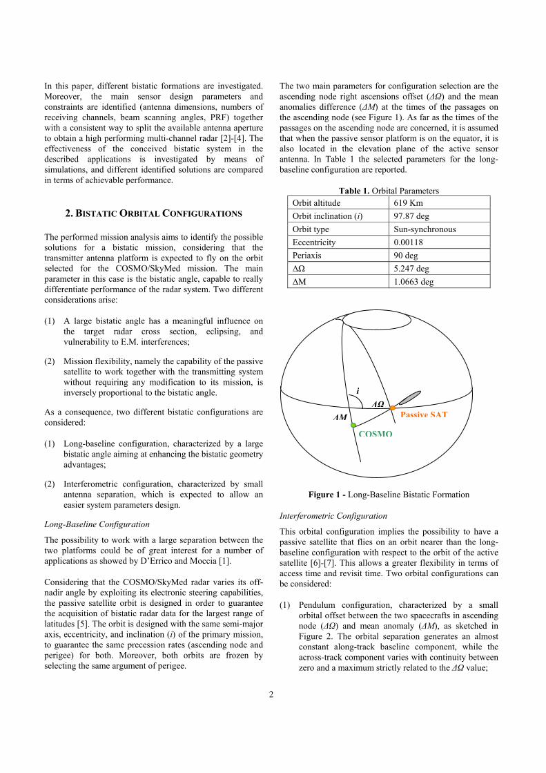
For the purpose of our analysis, we identify a possible solutions for the receiving antenna architecture together with a suitable set of Multi-Beam configurations, aiming at: (i) the largest reuse of what has already been developed for the SAR of COSMO/SkyMed; (ii) holding down the development costs of the passive SAR. Following these guidelines we consider an antenna characterized by the same dimensions and electrical architecture of the COSMO/SkyMed SAR antenna, even if only receiving. In the present design, the COSMO/SkyMed SAR antenna (5.7m×1.4m) is composed of 5 horizontal electrical panels of 8 vertical tiles each, as shown in Figure 3. Antenna parameters are reported in Table 3.
Table 3. COSMO-Like Antenna Parameter Antenna length in azimuth 5.6 m Antenna length in elevation 1.4 m Electronic steering in elevation ±15 deg Electronic steering in azimuth ±2 deg Antenna mechanical elevation angle 33.5 deg
∆M
∆Ω
Passive SAT COSMO
4
Lombardo et al. proposed different solutions to obtain multiple sub-apertures [2], showing that the antenna can easily be split into up to five channels by acting at the level of electrical panels. This operation does not require any modifications of the antenna tiles, therefore it has a limited impact on the original architecture.
Figure 3 – COSMO-Like Antenna
In the following a preliminary assessment of the multi-channel system capabilities is reported for all the considered applications, with reference to several multi-channel antenna configurations.
4. MTI APPLICATIONS
The detection and localization of slowly moving ground targets is of great potential interest for surveillance in both military and civil protection applications. In this regard, the proposed sensor is expected to allow extra potentialities with respect to the monostatic single-channel system, including:
(1) clutter cancellation and detection of moving targets (MTI – moving target indication) applying space-time adaptive processing (STAP) techniques on the multi-channel set of collected radar data;
(2) exact positioning and imaging of moving targets in the high resolution SAR images (MT-RELOC);
4.1 MTI-STAP
The key point in the detection of slow targets is their discrimination from the strong surface clutter echoes. A discrimination based only on the Doppler frequency is not effective for the slow targets, since the high satellite speed (LEO orbit) yields a wide clutter spectrum that spreads over their Doppler frequencies. Using multiple sub-apertures allows one to perform space-time clutter cancellation, with a much narrower notch than using Doppler information only, so slow targets can be detected.
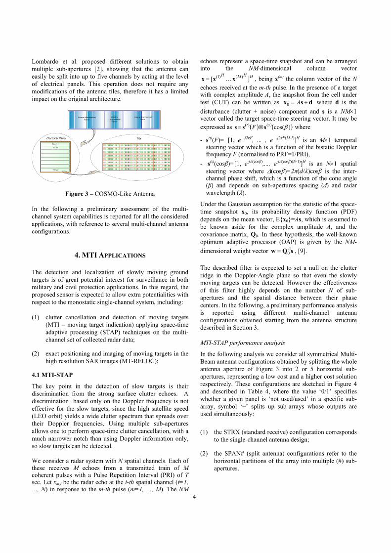
We consider a radar system with N spatial channels. Each of these receives M echoes from a transmitted train of M coherent pulses with a Pulse Repetition Interval (PRI) of T sec. Let xm,i be the radar echo at the i-th spatial channel (i=1, …, N) in response to the m-th pulse (m=1, …, M). The NM
echoes represent a space-time snapshot and can be arranged into the NM-dimensional column vector
HHMH] . . . [ )()1( xxx = , being x(m) the column vector of the N
echoes received at the m-th pulse. In the presence of a target with complex amplitude A, the snapshot from the cell under test (CUT) can be written as dsx += A0 where d is the disturbance (clutter + noise) component and s is a NM×1 vector called the target space-time steering vector. It may be expressed as ( ) ( ))cos()()( βst F sss ⊗= where
- s(t)(F)= [1, e -j2πF, ... , e -j2πF(M-1)]H is an M×1 temporal steering vector which is a function of the bistatic Doppler frequency F (normalised to PRF=1/PRI),
- s(s)(cosβ)=[1, e-j∆(cosβ),..., e-j∆(cosβ)(N-1)]H is an N×1 spatial steering vector where ∆(cosβ)=2π(d/λ)cosβ is the inter-channel phase shift, which is a function of the cone angle (β) and depends on sub-apertures spacing (d) and radar wavelength (λ).
Under the Gaussian assumption for the statistic of the space-time snapshot x0, its probability density function (PDF) depends on the mean vector, Ex0=As, which is assumed to be known aside for the complex amplitude A, and the covariance matrix, Q0. In these hypothesis, the well-known optimum adaptive processor (OAP) is given by the NM-dimensional weight vector sQw -1
0= , [9].
The described filter is expected to set a null on the clutter ridge in the Doppler-Angle plane so that even the slowly moving targets can be detected. However the effectiveness of this filter highly depends on the number N of sub-apertures and the spatial distance between their phase centers. In the following, a preliminary performance analysis is reported using different multi-channel antenna configurations obtained starting from the antenna structure described in Section 3.
MTI-STAP performance analysis
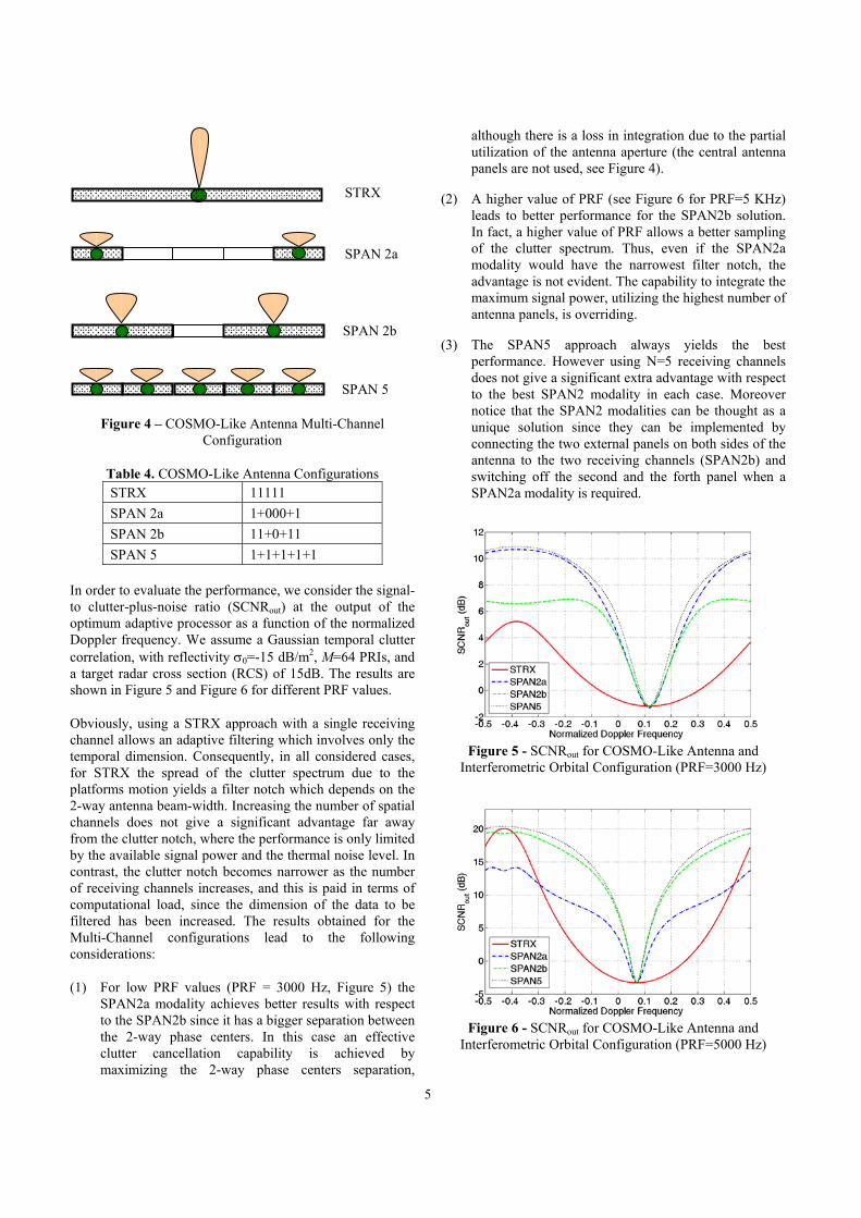
In the following analysis we consider all symmetrical Multi-Beam antenna configurations obtained by splitting the whole antenna aperture of Figure 3 into 2 or 5 horizontal sub-apertures, representing a low cost and a higher cost solution respectively. These configurations are sketched in Figure 4 and described in Table 4, where the value ‘0/1’ specifies whether a given panel is ‘not used/used’ in a specific sub-array, symbol ‘+’ splits up sub-arrays whose outputs are used simultaneously:
(1) the STRX (standard receive) configuration corresponds to the single-channel antenna design;
(2) the SPAN# (split antenna) configurations refer to the horizontal partitions of the array into multiple (#) sub-apertures.
Electrical Panel Tile
Tile #1
Tile #2
Tile #8
Lateral MechanicalPanel
Lateral MechanicalPanel
Central Mechanical
Panel
5
Figure 4 – COSMO-Like Antenna Multi-Channel Configuration
Table 4. COSMO-Like Antenna Configurations STRX 11111 SPAN 2a 1+000+1 SPAN 2b 11+0+11 SPAN 5 1+1+1+1+1
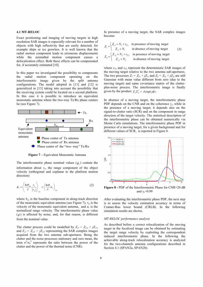
In order to evaluate the performance, we consider the signal-to clutter-plus-noise ratio (SCNRout) at the output of the optimum adaptive processor as a function of the normalized Doppler frequency. We assume a Gaussian temporal clutter correlation, with reflectivity σ0=-15 dB/m2, M=64 PRIs, and a target radar cross section (RCS) of 15dB. The results are shown in Figure 5 and Figure 6 for different PRF values.
Obviously, using a STRX approach with a single receiving channel allows an adaptive filtering which involves only the temporal dimension. Consequently, in all considered cases, for STRX the spread of the clutter spectrum due to the platforms motion yields a filter notch which depends on the 2-way antenna beam-width. Increasing the number of spatial channels does not give a significant advantage far away from the clutter notch, where the performance is only limited by the available signal power and the thermal noise level. In contrast, the clutter notch becomes narrower as the number of receiving channels increases, and this is paid in terms of computational load, since the dimension of the data to be filtered has been increased. The results obtained for the Multi-Channel configurations lead to the following considerations:
(1) For low PRF values (PRF = 3000 Hz, Figure 5) the SPAN2a modality achieves better results with respect to the SPAN2b since it has a bigger separation between the 2-way phase centers. In this case an effective clutter cancellation capability is achieved by maximizing the 2-way phase centers separation,
although there is a loss in integration due to the partial utilization of the antenna aperture (the central antenna panels are not used, see Figure 4).
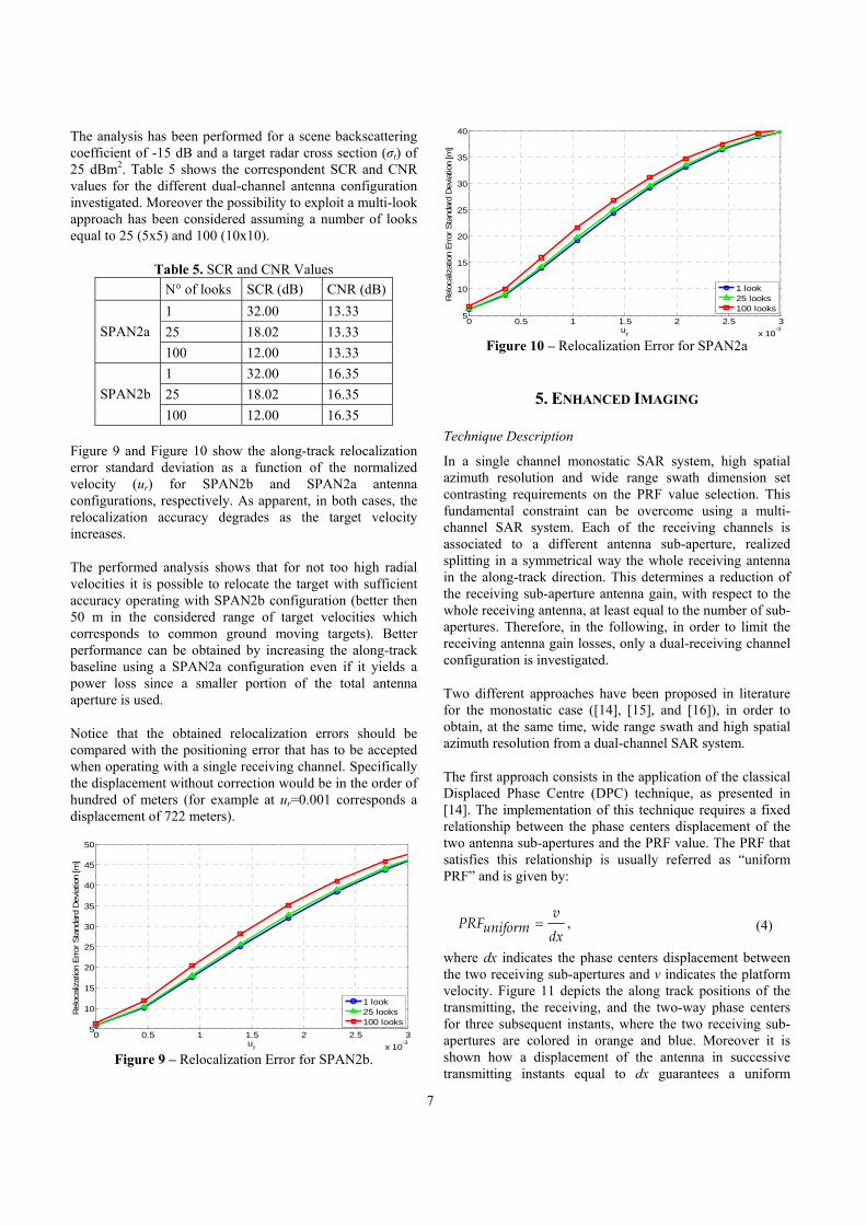
(2) A higher value of PRF (see Figure 6 for PRF=5 KHz) leads to better performance for the SPAN2b solution. In fact, a higher value of PRF allows a better sampling of the clutter spectrum. Thus, even if the SPAN2a modality would have the narrowest filter notch, the advantage is not evident. The capability to integrate the maximum signal power, utilizing the highest number of antenna panels, is overriding.
(3) The SPAN5 approach always yields the best performance. However using N=5 receiving channels does not give a significant extra advantage with respect to the best SPAN2 modality in each case. Moreover notice that the SPAN2 modalities can be thought as a unique solution since they can be implemented by connecting the two external panels on both sides of the antenna to the two receiving channels (SPAN2b) and switching off the second and the forth panel when a SPAN2a modality is required.
Figure 5 - SCNRout for COSMO-Like Antenna and
Interferometric Orbital Configuration (PRF=3000 Hz)
Figure 6 - SCNRout for COSMO-Like Antenna and
Interferometric Orbital Configuration (PRF=5000 Hz)
SPAN 2a
SPAN 2b
STRX
SPAN 5
6
4.1 MT-RELOC
Exact positioning and imaging of moving targets in high resolution SAR images is especially relevant for a number of objects with high reflectivity that are easily detected, for example ships or ice growlers. It is well known that the radial motion component leads to erroneous displacements while the azimuthal motion component causes a defocalization effect. Both these effects can be compensated for, if accurately estimated [10].
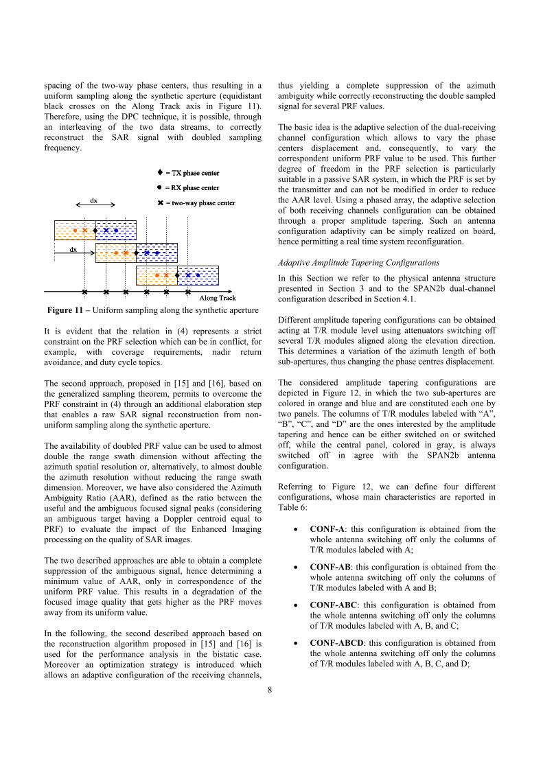
In this paper we investigated the possibility to compensate the radial motion component operating on the interferometric image given by the split antenna configurations. The model adopted in [11] and [12] is generalized in [13] taking into account the possibility that the receiving system could be located on a second platform. In this case it is possible to introduce an equivalent monostatic antenna where the two-way Tx/Rx phase centers lie (see Figure 7).
Figure 7 – Equivalent Monostatic Antenna
The interferometric phase nominal values ( vφ ) contain the information about vr, the range component of the object velocity (orthogonal and coplanar to the platform motion direction)
ππ
λπ
λπ
φ2
2
44r
p
razv ub
vvb
== (2)
where baz is the baseline component in along-track direction of the monostatic equivalent antenna (see Figure 7), vp is the velocity of the monostatic equivalent antenna, and ur is the normalized range velocity. The interferometric phase value (φ ) is affected by noise, and, for that reason, is different from the nominal value.
The clutter process could be modelled by Zc1 = Zc1r + jZc1i
and Zc2 = Zc2r + jZc2i representing the SAR complex images acquired from the two antenna sub-apertures. Being the clutter and the noise processes stationary and zero mean, the term σ2/σn
2 represents the ratio between the power of the clutter and the power of the thermal noise (CNR).
In presence of a moving target, the SAR complex images become:
+++
=
+++
=
argettmovingofabsenceinargettmovingofpresencein
argettmovingofabsenceinargettmovingofpresencein
22
2222
11
1111
NZzNZ
Z
NZzNZ
Z
c
Tc
c
Tc
(3)
where zT1 and zT2 represent the deterministic SAR images of the moving target relative to the two antenna sub-apertures. The two processes Z1 = Z1r + jZ1i and Z2 = Z2r + jZ2i are still Gaussian with mean value different from zero (due to the moving target) and same covariance matrix of the clutter-plus-noise process. The interferometric image is finally given by the product )exp(*
21 φjAZZ = .
In absence of a moving target, the interferometric phase PDF depends on the CNR and on the coherence γc, while in the presence of a moving target, it depends also on the signal-to-clutter ratio (SCR) and on the component in range direction of the target velocity. The statistical description of the interferometric phase can be obtained numerically via Monte Carlo simulations. The interferometric phase PDF in presence of a moving target, for a given background and for different values of SCR, is reported in Figure 8.
-3 -2 -1 0 1 2 30
0.5
1
1.5
2
2.5
φ
f φ(φ
)
SCR=0SCR=10SCR=20
Figure 8 - PDF of the Interferometric Phase for CNR=20 dB
and γc=0.99
After evaluating the interferometric phase PDF, the next step is to assess the velocity estimation accuracy in terms of Cramer-Rao lower bound (CRLB). In the following simulation results are shown.
MT-RELOC performance analysis
As described before a correct relocalization of the moving target in the focalized image can be obtained by estimating the target range velocity by exploiting the correspondent induced interferometric phase. In the following the achievable along-track relocalization accuracy is analyzed for the two-channels antenna configurations described in Section 4.1 (SPAN2a, SPAN2b).
Phase center of Tx antenna Phase center of Rx antenna
Phase center of the “two- way” Tx/Rx
Tx
Rx
Equivalent monostatic antenna
baz
7
The analysis has been performed for a scene backscattering coefficient of -15 dB and a target radar cross section (σt) of 25 dBm2. Table 5 shows the correspondent SCR and CNR values for the different dual-channel antenna configuration investigated. Moreover the possibility to exploit a multi-look approach has been considered assuming a number of looks equal to 25 (5x5) and 100 (10x10).
Table 5. SCR and CNR Values N° of looks SCR (dB) CNR (dB)
1 32.00 13.33 25 18.02 13.33 SPAN2a 100 12.00 13.33 1 32.00 16.35 25 18.02 16.35 SPAN2b 100 12.00 16.35
Figure 9 and Figure 10 show the along-track relocalization error standard deviation as a function of the normalized velocity (ur) for SPAN2b and SPAN2a antenna configurations, respectively. As apparent, in both cases, the relocalization accuracy degrades as the target velocity increases.
The performed analysis shows that for not too high radial velocities it is possible to relocate the target with sufficient accuracy operating with SPAN2b configuration (better then 50 m in the considered range of target velocities which corresponds to common ground moving targets). Better performance can be obtained by increasing the along-track baseline using a SPAN2a configuration even if it yields a power loss since a smaller portion of the total antenna aperture is used.
Notice that the obtained relocalization errors should be compared with the positioning error that has to be accepted when operating with a single receiving channel. Specifically the displacement without correction would be in the order of hundred of meters (for example at ur=0.001 corresponds a displacement of 722 meters).
0 0.5 1 1.5 2 2.5 3
x 10-3
5
10
15
20
25
30
35
40
45
50
ur
Rel
ocal
izat
ion
Err
or S
tand
ard
Dev
iatio
n [m
]
1 look25 looks100 looks
Figure 9 – Relocalization Error for SPAN2b.
0 0.5 1 1.5 2 2.5 3
x 10-3
5
10
15
20
25
30
35
40
ur
Rel
ocal
izat
ion
Err
or S
tand
ard
Dev
iatio
n [m
]
1 look25 looks100 looks
Figure 10 – Relocalization Error for SPAN2a
5. ENHANCED IMAGING
Technique Description
In a single channel monostatic SAR system, high spatial azimuth resolution and wide range swath dimension set contrasting requirements on the PRF value selection. This fundamental constraint can be overcome using a multi-channel SAR system. Each of the receiving channels is associated to a different antenna sub-aperture, realized splitting in a symmetrical way the whole receiving antenna in the along-track direction. This determines a reduction of the receiving sub-aperture antenna gain, with respect to the whole receiving antenna, at least equal to the number of sub-apertures. Therefore, in the following, in order to limit the receiving antenna gain losses, only a dual-receiving channel configuration is investigated.
Two different approaches have been proposed in literature for the monostatic case ([14], [15], and [16]), in order to obtain, at the same time, wide range swath and high spatial azimuth resolution from a dual-channel SAR system.
The first approach consists in the application of the classical Displaced Phase Centre (DPC) technique, as presented in [14]. The implementation of this technique requires a fixed relationship between the phase centers displacement of the two antenna sub-apertures and the PRF value. The PRF that satisfies this relationship is usually referred as “uniform PRF” and is given by:
dx
vuniformPRF = , (4)
where dx indicates the phase centers displacement between the two receiving sub-apertures and v indicates the platform velocity. Figure 11 depicts the along track positions of the transmitting, the receiving, and the two-way phase centers for three subsequent instants, where the two receiving sub-apertures are colored in orange and blue. Moreover it is shown how a displacement of the antenna in successive transmitting instants equal to dx guarantees a uniform
8
spacing of the two-way phase centers, thus resulting in a uniform sampling along the synthetic aperture (equidistant black crosses on the Along Track axis in Figure 11). Therefore, using the DPC technique, it is possible, through an interleaving of the two data streams, to correctly reconstruct the SAR signal with doubled sampling frequency.
× ♦ ×
× ♦ ×
× ♦ ×
dx
dx
= two-way phase center
♦ = TX phase center
= RX phase center
×
× × × × × ×Along Track
× ♦ ×
× ♦ ×
× ♦ ×
dx
dx
= two-way phase center
♦ = TX phase center
= RX phase center
× = two-way phase center
♦ = TX phase center
= RX phase center
×
× × × × × ×Along Track
Figure 11 – Uniform sampling along the synthetic aperture
It is evident that the relation in (4) represents a strict constraint on the PRF selection which can be in conflict, for example, with coverage requirements, nadir return avoidance, and duty cycle topics.
The second approach, proposed in [15] and [16], based on the generalized sampling theorem, permits to overcome the PRF constraint in (4) through an additional elaboration step that enables a raw SAR signal reconstruction from non-uniform sampling along the synthetic aperture.
The availability of doubled PRF value can be used to almost double the range swath dimension without affecting the azimuth spatial resolution or, alternatively, to almost double the azimuth resolution without reducing the range swath dimension. Moreover, we have also considered the Azimuth Ambiguity Ratio (AAR), defined as the ratio between the useful and the ambiguous focused signal peaks (considering an ambiguous target having a Doppler centroid equal to PRF) to evaluate the impact of the Enhanced Imaging processing on the quality of SAR images.
The two described approaches are able to obtain a complete suppression of the ambiguous signal, hence determining a minimum value of AAR, only in correspondence of the uniform PRF value. This results in a degradation of the focused image quality that gets higher as the PRF moves away from its uniform value.
In the following, the second described approach based on the reconstruction algorithm proposed in [15] and [16] is used for the performance analysis in the bistatic case. Moreover an optimization strategy is introduced which allows an adaptive configuration of the receiving channels,
thus yielding a complete suppression of the azimuth ambiguity while correctly reconstructing the double sampled signal for several PRF values.
The basic idea is the adaptive selection of the dual-receiving channel configuration which allows to vary the phase centers displacement and, consequently, to vary the correspondent uniform PRF value to be used. This further degree of freedom in the PRF selection is particularly suitable in a passive SAR system, in which the PRF is set by the transmitter and can not be modified in order to reduce the AAR level. Using a phased array, the adaptive selection of both receiving channels configuration can be obtained through a proper amplitude tapering. Such an antenna configuration adaptivity can be simply realized on board, hence permitting a real time system reconfiguration.
Adaptive Amplitude Tapering Configurations
In this Section we refer to the physical antenna structure presented in Section 3 and to the SPAN2b dual-channel configuration described in Section 4.1.
Different amplitude tapering configurations can be obtained acting at T/R module level using attenuators switching off several T/R modules aligned along the elevation direction. This determines a variation of the azimuth length of both sub-apertures, thus changing the phase centres displacement.
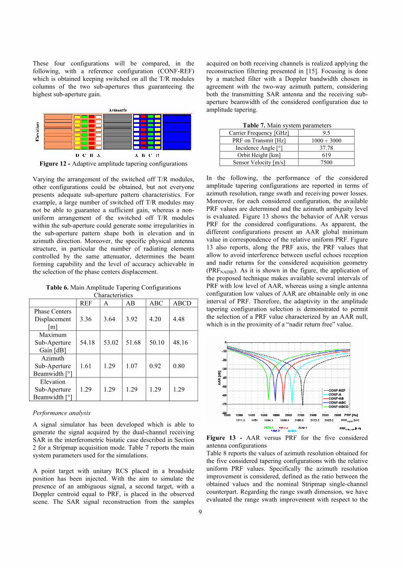
The considered amplitude tapering configurations are depicted in Figure 12, in which the two sub-apertures are colored in orange and blue and are constituted each one by two panels. The columns of T/R modules labeled with “A”, “B”, “C”, and “D” are the ones interested by the amplitude tapering and hence can be either switched on or switched off, while the central panel, colored in gray, is always switched off in agree with the SPAN2b antenna configuration.
Referring to Figure 12, we can define four different configurations, whose main characteristics are reported in Table 6:
• CONF-A: this configuration is obtained from the whole antenna switching off only the columns of T/R modules labeled with A;
• CONF-AB: this configuration is obtained from the whole antenna switching off only the columns of T/R modules labeled with A and B;
• CONF-ABC: this configuration is obtained from the whole antenna switching off only the columns of T/R modules labeled with A, B, and C;
• CONF-ABCD: this configuration is obtained from the whole antenna switching off only the columns of T/R modules labeled with A, B, C, and D;
9
These four configurations will be compared, in the following, with a reference configuration (CONF-REF) which is obtained keeping switched on all the T/R modules columns of the two sub-apertures thus guaranteeing the highest sub-aperture gain.
Figure 12 - Adaptive amplitude tapering configurations
Varying the arrangement of the switched off T/R modules, other configurations could be obtained, but not everyone presents adequate sub-aperture pattern characteristics. For example, a large number of switched off T/R modules may not be able to guarantee a sufficient gain, whereas a non-uniform arrangement of the switched off T/R modules within the sub-aperture could generate some irregularities in the sub-aperture pattern shape both in elevation and in azimuth direction. Moreover, the specific physical antenna structure, in particular the number of radiating elements controlled by the same attenuator, determines the beam forming capability and the level of accuracy achievable in the selection of the phase centers displacement.
Table 6. Main Amplitude Tapering Configurations Characteristics
REF A AB ABC ABCD Phase Centers Displacement
[m] 3.36 3.64 3.92 4.20 4.48
Maximum Sub-Aperture
Gain [dB] 54.18 53.02 51.68 50.10 48.16
Azimuth Sub-Aperture Beamwidth [°]
1.61 1.29 1.07 0.92 0.80
Elevation Sub-Aperture Beamwidth [°]
1.29 1.29 1.29 1.29 1.29
Performance analysis
A signal simulator has been developed which is able to generate the signal acquired by the dual-channel receiving SAR in the interferometric bistatic case described in Section 2 for a Stripmap acquisition mode. Table 7 reports the main system parameters used for the simulations.
A point target with unitary RCS placed in a broadside position has been injected. With the aim to simulate the presence of an ambiguous signal, a second target, with a Doppler centroid equal to PRF, is placed in the observed scene. The SAR signal reconstruction from the samples
acquired on both receiving channels is realized applying the reconstruction filtering presented in [15]. Focusing is done by a matched filter with a Doppler bandwidth chosen in agreement with the two-way azimuth pattern, considering both the transmitting SAR antenna and the receiving sub-aperture beamwidth of the considered configuration due to amplitude tapering.
Table 7. Main system parameters Carrier Frequency [GHz] 9.5
PRF on Transmit [Hz] 1000 ÷ 3000 Incidence Angle [°] 37.78 Orbit Height [km] 619
Sensor Velocity [m/s] 7500 In the following, the performance of the considered amplitude tapering configurations are reported in terms of azimuth resolution, range swath and receiving power losses. Moreover, for each considered configuration, the available PRF values are determined and the azimuth ambiguity level is evaluated. Figure 13 shows the behavior of AAR versus PRF for the considered configurations. As apparent, the different configurations present an AAR global minimum value in correspondence of the relative uniform PRF. Figure 13 also reports, along the PRF axis, the PRF values that allow to avoid interference between useful echoes reception and nadir returns for the considered acquisition geometry (PRFNADIR). As it is shown in the figure, the application of the proposed technique makes available several intervals of PRF with low level of AAR, whereas using a single antenna configuration low values of AAR are obtainable only in one interval of PRF. Therefore, the adaptivity in the amplitude tapering configuration selection is demonstrated to permit the selection of a PRF value characterized by an AAR null, which is in the proximity of a “nadir return free” value.
Figure 13 - AAR versus PRF for the five considered antenna configurations Table 8 reports the values of azimuth resolution obtained for the five considered tapering configurations with the relative uniform PRF values. Specifically the azimuth resolution improvement is considered, defined as the ratio between the obtained values and the nominal Stripmap single-channel counterpart. Regarding the range swath dimension, we have evaluated the range swath improvement with respect to the
10
swath dimension obtained for the reference configuration (CONF-REF).
Table 8. Simulation results REF A AB ABC ABCD
AAR [dB] -71.70 -70.03 -68.17 -66.29 -64.85 Azimuth
Resolution [m] 2.11 2.09 2.08 2.10 2.15
Uniform PRF [Hz] 2232.1 2060.4 1913.3 1785.7 1674.1
Azimuth Resolution
Improvement 32.7% 33.9% 34.6% 33.3% 30.2%
Range Swath Dimension
Improvement - 8.33% 16.6% 25% 33.3%
As apparent all the five tapering configurations permit to achieve an improvement in the image geometric characteristics. In particular, as the phase centres displacement increases (moving from CONF-REF to CONF-ABCD), the uniform PRF value decreases, thus permitting to improve the range swath dimension. Regarding the azimuth resolution, we can observe that all the considered configurations achieve an improvement with respect to the nominal Stripmap single-channel counterpart. Moving from CONF-REF to CONF-ABCD the sub-aperture azimuth length decreases thus leading to a theoretical improvement in the azimuth resolution. However this improvement can not be practically achieved in the considered Stripmap acquisition mode since the transmitter azimuth pattern beamwidth sets a constraint on the maximum synthetic aperture length. If a cooperation between the transmitter and the receiver SAR sensors is available, this problem can be simply overcome varying the azimuth pattern beamwidth of the transmitting antenna.
As mentioned before, the proposed approach for enhanced imaging can be simply extended to a N-channel SAR system, thus theoretically allowing a further improvement in azimuth resolution or range swath dimension if a proportional gain loss can be accepted.
6. ELECTRONIC COUNTER COUNTER MEASURES
The imaging capability of a SAR could be seriously limited or denied by an electromagnetic interference signal impinging on the antenna array during the synthetic aperture. Such interference could be both intentional (i.e. Jamming) or due to a spurious transmission in the same frequency band in which SAR operates (i.e. RFI, Radio Frequency Interference). Moreover, the SAR pulse transmitted power is penalized by 2-way propagation losses, while interference power has only 1-way propagation losses. Thus, even if the interference transmitted power is not high and it is received by the side-lobes of the SAR antenna, it can deny the SAR imaging capability. For imaging radars,
the effect of a wideband noise-like interference is to mask the scene visible in the imaged area with a high uniform noise level. [17] [18]
The availability of multiple receiving channels allows the application of antenna nulling techniques to reduce the effects of interferences over the collected SAR data, thus fundamentally allowing a normal operation despite the presence of the continuous wave disturbance signals. [19]
SAR vulnerability to e.m. interferences
To evaluate the vulnerability of a space-borne SAR sensor to a noise-like interference signal transmitted from the ground, we consider several scenarios for the interference and evaluate the Signal to Interference plus Noise Ratio (SINR) obtained, after imaging, considering the reflection of a thick spaced grid of targets around the interference source. The vulnerability measure of a SAR was defined as the imaged area over which a jammer denies information acquisition. Two thresholds are applied to the obtained SINR to extract a map of the region where new target detection capabilities or target confirmation capabilities are denied. [17]
In Table 9 the interference parameters for the considered scenarios are reported. We consider the worst interference scenario where radar signal and interference band are matched and the interference is present for all the synthetic aperture.
Table 9. Interference parameters
Interference EIRP (EIRPJ) - 50 dBW - 70 dBW
Interference incidence angle (θiJ) - 30° - 70°
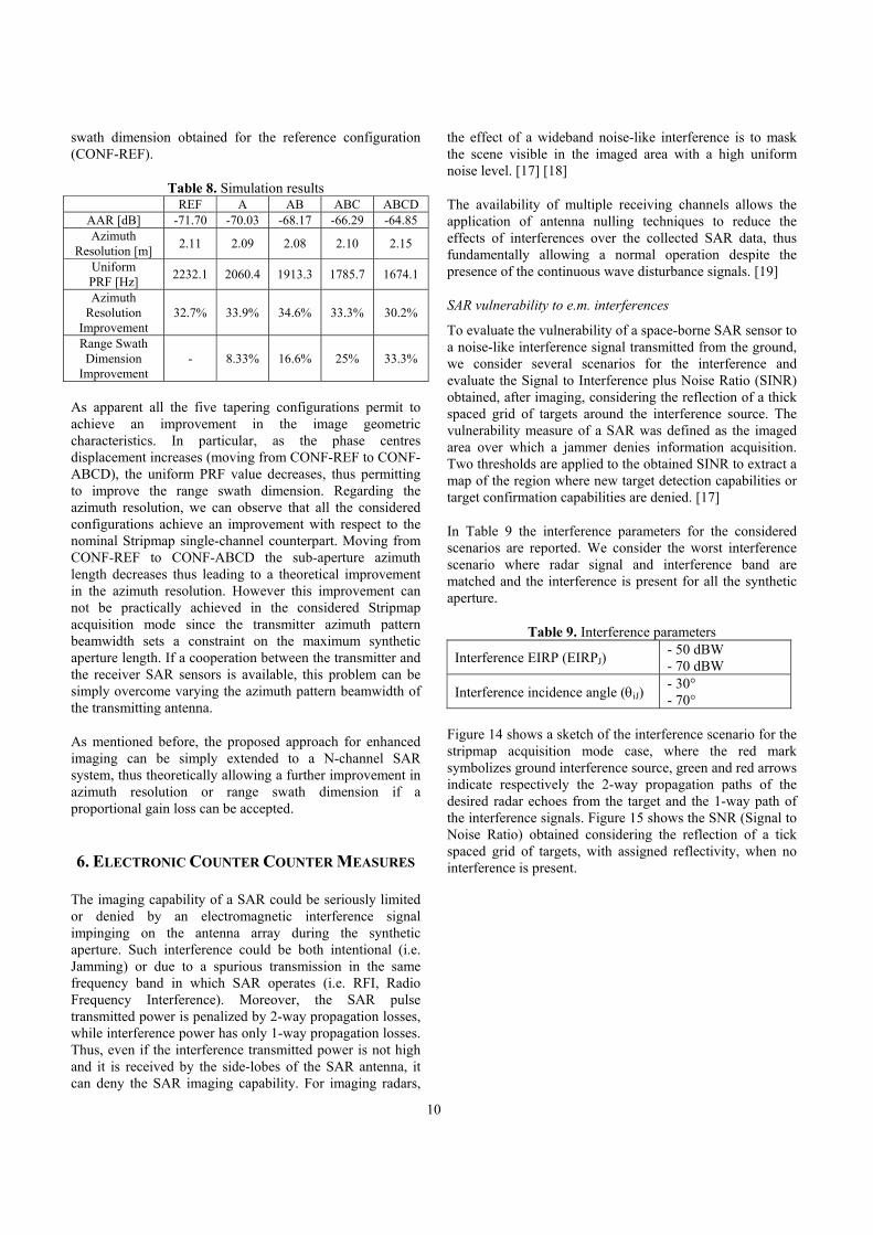
Figure 14 shows a sketch of the interference scenario for the stripmap acquisition mode case, where the red mark symbolizes ground interference source, green and red arrows indicate respectively the 2-way propagation paths of the desired radar echoes from the target and the 1-way path of the interference signals. Figure 15 shows the SNR (Signal to Noise Ratio) obtained considering the reflection of a tick spaced grid of targets, with assigned reflectivity, when no interference is present.
11
Figure 14 – Stripmap interference scenario
Figure 15 - Map of SNR for stripmap mode, no interference
present
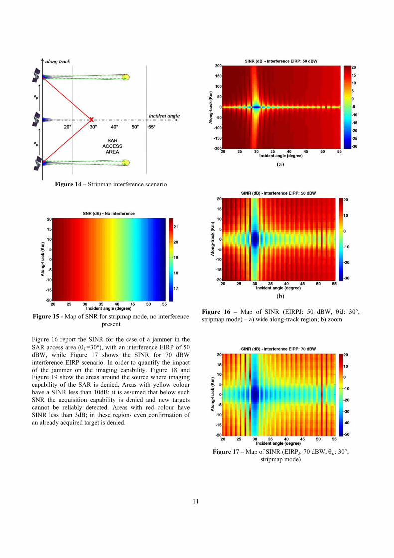
Figure 16 report the SINR for the case of a jammer in the SAR access area (θiJ=30°), with an interference EIRP of 50 dBW, while Figure 17 shows the SINR for 70 dBW interference EIRP scenario. In order to quantify the impact of the jammer on the imaging capability, Figure 18 and Figure 19 show the areas around the source where imaging capability of the SAR is denied. Areas with yellow colour have a SINR less than 10dB; it is assumed that below such SNR the acquisition capability is denied and new targets cannot be reliably detected. Areas with red colour have SINR less than 3dB; in these regions even confirmation of an already acquired target is denied.
(a)
(b)
Figure 16 – Map of SINR (EIRPJ: 50 dBW, θiJ: 30°, stripmap mode) – a) wide along-track region; b) zoom
Figure 17 – Map of SINR (EIRPJ: 70 dBW, θiJ: 30°,
stripmap mode)
12
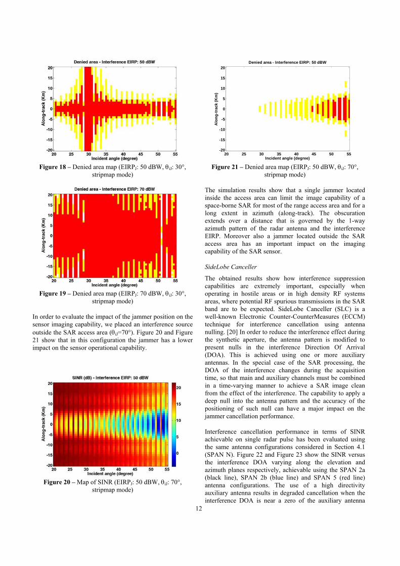
Figure 18 – Denied area map (EIRPJ: 50 dBW, θiJ: 30°,
stripmap mode)
Figure 19 – Denied area map (EIRPJ: 70 dBW, θiJ: 30°,
stripmap mode)
In order to evaluate the impact of the jammer position on the sensor imaging capability, we placed an interference source outside the SAR access area (θiJ=70°). Figure 20 and Figure 21 show that in this configuration the jammer has a lower impact on the sensor operational capability.
Figure 20 – Map of SINR (EIRPJ: 50 dBW, θiJ: 70°,
stripmap mode)
Incident angle (degree)
Alo
ng
-tra
ck (
Km
)
Denied area - Interference EIRP: 50 dBW
20 25 30 35 40 45 50 55-20
-15
-10
-5
0
5
10
15
20
Figure 21 – Denied area map (EIRPJ: 50 dBW, θiJ: 70°,
stripmap mode)
The simulation results show that a single jammer located inside the access area can limit the image capability of a space-borne SAR for most of the range access area and for a long extent in azimuth (along-track). The obscuration extends over a distance that is governed by the 1-way azimuth pattern of the radar antenna and the interference EIRP. Moreover also a jammer located outside the SAR access area has an important impact on the imaging capability of the SAR sensor.
SideLobe Canceller
The obtained results show how interference suppression capabilities are extremely important, especially when operating in hostile areas or in high density RF systems areas, where potential RF spurious transmissions in the SAR band are to be expected. SideLobe Canceller (SLC) is a well-known Electronic Counter-CounterMeasures (ECCM) technique for interference cancellation using antenna nulling. [20] In order to reduce the interference effect during the synthetic aperture, the antenna pattern is modified to present nulls in the interference Direction Of Arrival (DOA). This is achieved using one or more auxiliary antennas. In the special case of the SAR processing, the DOA of the interference changes during the acquisition time, so that main and auxiliary channels must be combined in a time-varying manner to achieve a SAR image clean from the effect of the interference. The capability to apply a deep null into the antenna pattern and the accuracy of the positioning of such null can have a major impact on the jammer cancellation performance.
Interference cancellation performance in terms of SINR achievable on single radar pulse has been evaluated using the same antenna configurations considered in Section 4.1 (SPAN N). Figure 22 and Figure 23 show the SINR versus the interference DOA varying along the elevation and azimuth planes respectively, achievable using the SPAN 2a (black line), SPAN 2b (blue line) and SPAN 5 (red line) antenna configurations. The use of a high directivity auxiliary antenna results in degraded cancellation when the interference DOA is near a zero of the auxiliary antenna
13
pattern. Moreover the SPAN N antenna configurations have no interference cancellation capability on the elevation plane due to their symmetric configuration and lined up phase centres (on the elevation plane) for the receiver channels.
85 86 87 88 89 90 91 92 93 94 95-30
-20
-10
0
10
20
30
40
50SINR (SNR=0 dB, JNR=20 dB)
φJ° (azimuth plane)
SIN
R (
dB
)
SPAN 2aSPAN 2bSPAN 5
Figure 22 – Cancellation performance achievable using the SPAN N antenna configurations (azimuth plane)
-15 -10 -5 0 5 10 15-30
-20
-10
0
10
20
30
40
50SINR (SNR=0 dB, JNR=20 dB)
θJ° (elevation plane)
SIN
R (
dB
)
SPAN 2aSPAN 2bSPAN5
Figure 23 – Cancellation performance achievable using the SPAN N antenna configurations (elevation plane)
Due the major drawbacks of the SPAN N antenna configurations for interference cancellation, other two ones have been investigated:
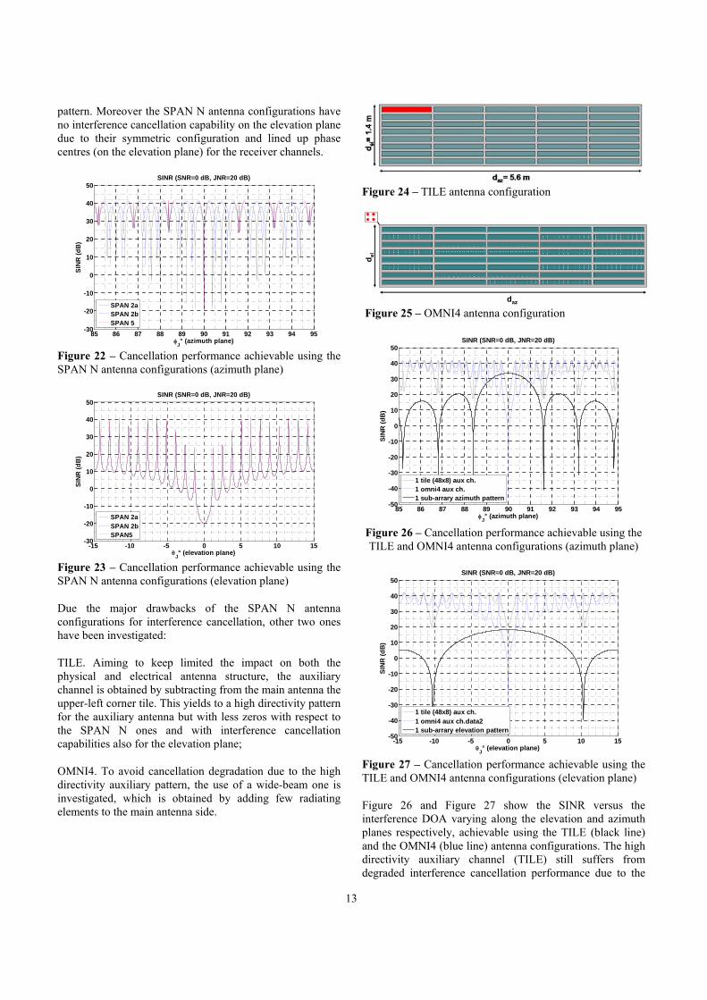
TILE. Aiming to keep limited the impact on both the physical and electrical antenna structure, the auxiliary channel is obtained by subtracting from the main antenna the upper-left corner tile. This yields to a high directivity pattern for the auxiliary antenna but with less zeros with respect to the SPAN N ones and with interference cancellation capabilities also for the elevation plane;
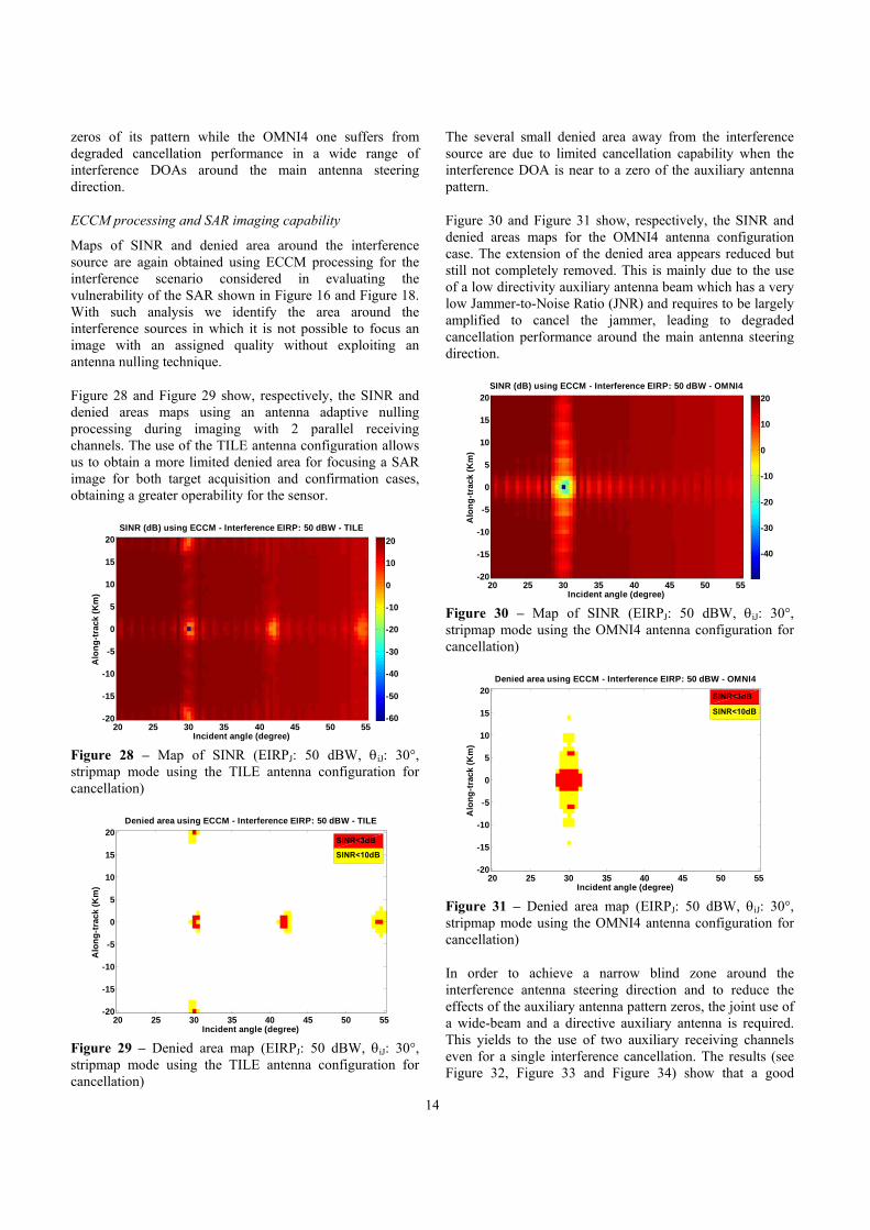
OMNI4. To avoid cancellation degradation due to the high directivity auxiliary pattern, the use of a wide-beam one is investigated, which is obtained by adding few radiating elements to the main antenna side.
Figure 24 – TILE antenna configuration
Figure 25 – OMNI4 antenna configuration
85 86 87 88 89 90 91 92 93 94 95-50
-40
-30
-20
-10
0
10
20
30
40
50SINR (SNR=0 dB, JNR=20 dB)
φJ° (azimuth plane)
SIN
R (
dB
)
1 tile (48x8) aux ch.1 omni4 aux ch.1 sub-arrary azimuth pattern
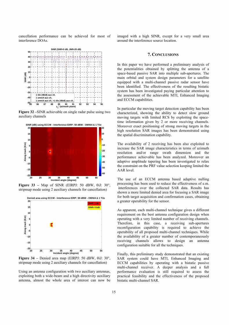
Figure 26 – Cancellation performance achievable using the TILE and OMNI4 antenna configurations (azimuth plane)
-15 -10 -5 0 5 10 15-50
-40
-30
-20
-10
0
10
20
30
40
50SINR (SNR=0 dB, JNR=20 dB)
θJ° (elevation plane)
SIN
R (
dB
)
1 tile (48x8) aux ch.1 omni4 aux ch.data21 sub-arrary elevation pattern
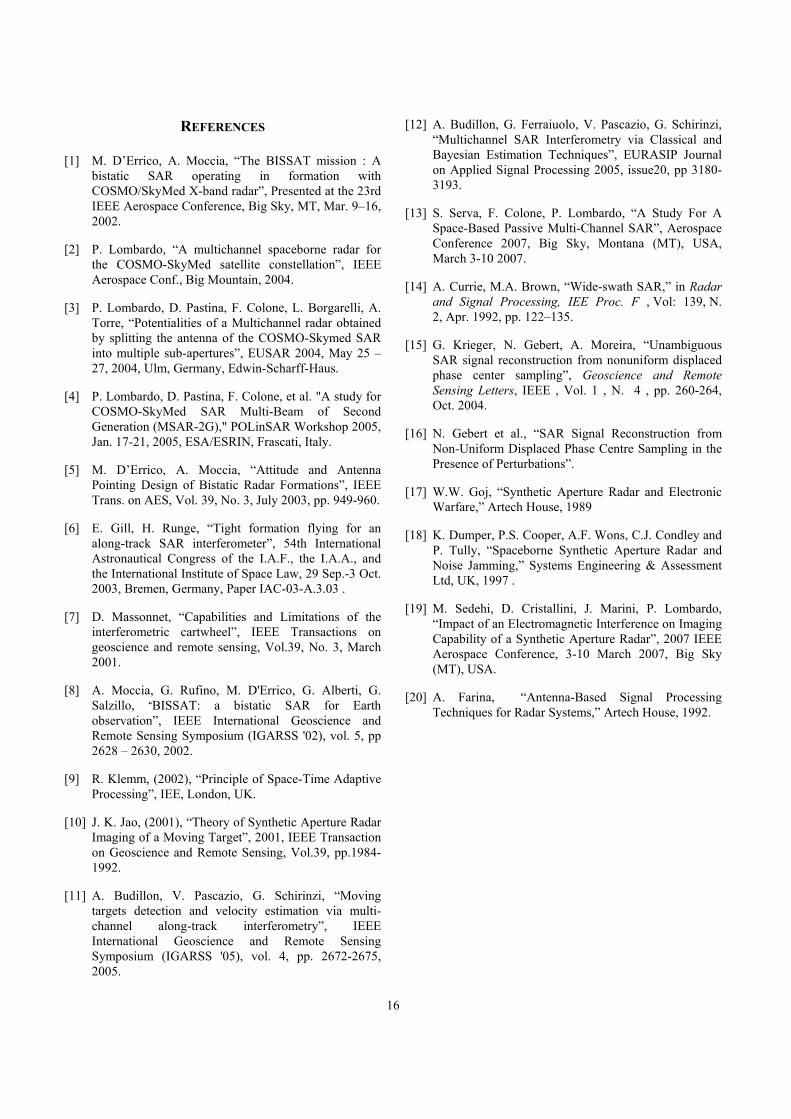
Figure 27 – Cancellation performance achievable using the TILE and OMNI4 antenna configurations (elevation plane)
Figure 26 and Figure 27 show the SINR versus the interference DOA varying along the elevation and azimuth planes respectively, achievable using the TILE (black line) and the OMNI4 (blue line) antenna configurations. The high directivity auxiliary channel (TILE) still suffers from degraded interference cancellation performance due to the
daz
d el
14
zeros of its pattern while the OMNI4 one suffers from degraded cancellation performance in a wide range of interference DOAs around the main antenna steering direction.
ECCM processing and SAR imaging capability
Maps of SINR and denied area around the interference source are again obtained using ECCM processing for the interference scenario considered in evaluating the vulnerability of the SAR shown in Figure 16 and Figure 18. With such analysis we identify the area around the interference sources in which it is not possible to focus an image with an assigned quality without exploiting an antenna nulling technique.
Figure 28 and Figure 29 show, respectively, the SINR and denied areas maps using an antenna adaptive nulling processing during imaging with 2 parallel receiving channels. The use of the TILE antenna configuration allows us to obtain a more limited denied area for focusing a SAR image for both target acquisition and confirmation cases, obtaining a greater operability for the sensor.
SINR (dB) using ECCM - Interference EIRP: 50 dBW - TILE
Alo
ng
-tra
ck (
Km
)
Incident angle (degree)
20 25 30 35 40 45 50 55-20
-15
-10
-5
0
5
10
15
20
-60
-50
-40
-30
-20
-10
0
10
20
Figure 28 – Map of SINR (EIRPJ: 50 dBW, θiJ: 30°, stripmap mode using the TILE antenna configuration for cancellation)
Incident angle (degree)
Alo
ng
-tra
ck (
Km
)
Denied area using ECCM - Interference EIRP: 50 dBW - TILE
20 25 30 35 40 45 50 55-20
-15
-10
-5
0
5
10
15
20SINR<3dB
SINR<10dB
Figure 29 – Denied area map (EIRPJ: 50 dBW, θiJ: 30°, stripmap mode using the TILE antenna configuration for cancellation)
The several small denied area away from the interference source are due to limited cancellation capability when the interference DOA is near to a zero of the auxiliary antenna pattern.
Figure 30 and Figure 31 show, respectively, the SINR and denied areas maps for the OMNI4 antenna configuration case. The extension of the denied area appears reduced but still not completely removed. This is mainly due to the use of a low directivity auxiliary antenna beam which has a very low Jammer-to-Noise Ratio (JNR) and requires to be largely amplified to cancel the jammer, leading to degraded cancellation performance around the main antenna steering direction.
SINR (dB) using ECCM - Interference EIRP: 50 dBW - OMNI4
Incident angle (degree)
Alo
ng
-tra
ck (
Km
)
20 25 30 35 40 45 50 55-20
-15
-10
-5
0
5
10
15
20
-40
-30
-20
-10
0
10
20
Figure 30 – Map of SINR (EIRPJ: 50 dBW, θiJ: 30°, stripmap mode using the OMNI4 antenna configuration for cancellation)
Incident angle (degree)
Alo
ng
-tra
ck (
Km
)
Denied area using ECCM - Interference EIRP: 50 dBW - OMNI4
20 25 30 35 40 45 50 55-20
-15
-10
-5
0
5
10
15
20 SINR<3dB
SINR<10dB
Figure 31 – Denied area map (EIRPJ: 50 dBW, θiJ: 30°, stripmap mode using the OMNI4 antenna configuration for cancellation)
In order to achieve a narrow blind zone around the interference antenna steering direction and to reduce the effects of the auxiliary antenna pattern zeros, the joint use of a wide-beam and a directive auxiliary antenna is required. This yields to the use of two auxiliary receiving channels even for a single interference cancellation. The results (see Figure 32, Figure 33 and Figure 34) show that a good
15
cancellation performance can be achieved for most of interference DOAs.
85 86 87 88 89 90 91 92 93 94 95-50
-40
-30
-20
-10
0
10
20
30
40
50SINR (SNR=0 dB, JNR=20 dB)
φJ° (azimuth plane)
SIN
R (
dB
)
1 tile (48x8) aux ch.1 omni4 aux ch.1 omni4 aux ch. +1 tile (48x8) aux ch.
Figure 32 –SINR achievable on single radar pulse using two auxiliary channels
SINR (dB) using ECCM - Interference EIRP: 50 dBW - OMNI4 & 1 Tile
Incident angle (degree)
Alo
ng
-tra
ck (
Km
)
20 25 30 35 40 45 50 55-20
-15
-10
-5
0
5
10
15
20
-60
-50
-40
-30
-20
-10
0
10
20
Figure 33 – Map of SINR (EIRPJ: 50 dBW, θiJ: 30°, stripmap mode using 2 auxiliary channels for cancellation)
Incident angle (degree)
Alo
ng
-tra
ck (
Km
)
Denied area using ECCM - Interference EIRP: 50 dBW - OMNI4 & 1 Tile
20 25 30 35 40 45 50 55-20
-15
-10
-5
0
5
10
15
20SINR<3dB
SINR<10dB
Figure 34 – Denied area map (EIRPJ: 50 dBW, θiJ: 30°, stripmap mode using 2 auxiliary channels for cancellation)
Using an antenna configuration with two auxiliary antennas, exploiting both a wide-beam and a high directivity auxiliary antenna, almost the whole area of interest can now be
imaged with a high SINR, except for a very small area around the interference source location.
7. CONCLUSIONS
In this paper we have performed a preliminary analysis of the potentialities obtained by splitting the antenna of a space-based passive SAR into multiple sub-apertures. The main orbital and system design parameters for a satellite equipped with a multi-channel passive radar sensor have been identified. The effectiveness of the resulting bistatic system has been investigated paying particular attention to the assessment of the achievable MTI, Enhanced Imaging and ECCM capabilities.
In particular the moving target detection capability has been characterized, showing the ability to detect slow ground moving targets with limited RCS by exploiting the space-time information given by 2 or more receiving channels. Moreover exact positioning of strong moving targets in the high resolution SAR images has been demonstrated using the spatial discrimination capability.
The availability of 2 receiving has been also exploited to increase the SAR image characteristics in terms of azimuth resolution and/or range swath dimension and the performance achievable has been analyzed. Moreover an adaptive amplitude tapering has been investigated to relax the constraint on the PRF value selection keeping limited the AAR level.
The use of an ECCM antenna based adaptive nulling processing has been used to reduce the effectiveness of e.m. interferences over the collected SAR data. Results has shown a more limited denied area for focusing a SAR image for both target acquisition and confirmation cases, obtaining a greater operability for the sensor.
As apparent, each multi-channel technique gives a different requirement on the best antenna configuration design when operating with a very limited number of receiving channels. Therefore, in this case, a receiving sub-apertures reconfiguration capability is required to achieve the operability of all proposed multi-channel techniques. While the availability of a greater number of contemporaneously receiving channels allows to design an antenna configuration suitable for all the techniques.
Finally, this preliminary study demonstrated that an existing SAR system could have MTI, Enhanced Imaging and ECCM capabilities by operating with a bistatic passive multi-channel receiver. A deeper analysis and a full performance evaluation is still required to assess the practical feasibility and the effectiveness of the proposed bistatic multi-channel SAR.
16
REFERENCES
[1] M. D’Errico, A. Moccia, “The BISSAT mission : A bistatic SAR operating in formation with COSMO/SkyMed X-band radar”, Presented at the 23rd IEEE Aerospace Conference, Big Sky, MT, Mar. 9–16, 2002.
[2] P. Lombardo, “A multichannel spaceborne radar for the COSMO-SkyMed satellite constellation”, IEEE Aerospace Conf., Big Mountain, 2004.
[3] P. Lombardo, D. Pastina, F. Colone, L. Borgarelli, A. Torre, “Potentialities of a Multichannel radar obtained by splitting the antenna of the COSMO-Skymed SAR into multiple sub-apertures”, EUSAR 2004, May 25 – 27, 2004, Ulm, Germany, Edwin-Scharff-Haus.
[4] P. Lombardo, D. Pastina, F. Colone, et al. "A study for COSMO-SkyMed SAR Multi-Beam of Second Generation (MSAR-2G)," POLinSAR Workshop 2005, Jan. 17-21, 2005, ESA/ESRIN, Frascati, Italy.
[5] M. D’Errico, A. Moccia, “Attitude and Antenna Pointing Design of Bistatic Radar Formations”, IEEE Trans. on AES, Vol. 39, No. 3, July 2003, pp. 949-960.
[6] E. Gill, H. Runge, “Tight formation flying for an along-track SAR interferometer”, 54th International Astronautical Congress of the I.A.F., the I.A.A., and the International Institute of Space Law, 29 Sep.-3 Oct. 2003, Bremen, Germany, Paper IAC-03-A.3.03 .
[7] D. Massonnet, “Capabilities and Limitations of the interferometric cartwheel”, IEEE Transactions on geoscience and remote sensing, Vol.39, No. 3, March 2001.
[8] A. Moccia, G. Rufino, M. D'Errico, G. Alberti, G. Salzillo, “BISSAT: a bistatic SAR for Earth observation”, IEEE International Geoscience and Remote Sensing Symposium (IGARSS '02), vol. 5, pp 2628 – 2630, 2002.
[9] R. Klemm, (2002), “Principle of Space-Time Adaptive Processing”, IEE, London, UK.
[10] J. K. Jao, (2001), “Theory of Synthetic Aperture Radar Imaging of a Moving Target”, 2001, IEEE Transaction on Geoscience and Remote Sensing, Vol.39, pp.1984-1992.
[11] A. Budillon, V. Pascazio, G. Schirinzi, “Moving targets detection and velocity estimation via multi-channel along-track interferometry”, IEEE International Geoscience and Remote Sensing Symposium (IGARSS '05), vol. 4, pp. 2672-2675, 2005.
[12] A. Budillon, G. Ferraiuolo, V. Pascazio, G. Schirinzi, “Multichannel SAR Interferometry via Classical and Bayesian Estimation Techniques”, EURASIP Journal on Applied Signal Processing 2005, issue20, pp 3180-3193.
[13] S. Serva, F. Colone, P. Lombardo, “A Study For A Space-Based Passive Multi-Channel SAR”, Aerospace Conference 2007, Big Sky, Montana (MT), USA, March 3-10 2007.
[14] A. Currie, M.A. Brown, “Wide-swath SAR,” in Radar and Signal Processing, IEE Proc. F , Vol: 139, N. 2, Apr. 1992, pp. 122–135.
[15] G. Krieger, N. Gebert, A. Moreira, “Unambiguous SAR signal reconstruction from nonuniform displaced phase center sampling”, Geoscience and Remote Sensing Letters, IEEE , Vol. 1 , N. 4 , pp. 260-264, Oct. 2004.
[16] N. Gebert et al., “SAR Signal Reconstruction from Non-Uniform Displaced Phase Centre Sampling in the Presence of Perturbations”.
[17] W.W. Goj, “Synthetic Aperture Radar and Electronic Warfare,” Artech House, 1989
[18] K. Dumper, P.S. Cooper, A.F. Wons, C.J. Condley and P. Tully, “Spaceborne Synthetic Aperture Radar and Noise Jamming,” Systems Engineering & Assessment Ltd, UK, 1997 .
[19] M. Sedehi, D. Cristallini, J. Marini, P. Lombardo, “Impact of an Electromagnetic Interference on Imaging Capability of a Synthetic Aperture Radar”, 2007 IEEE Aerospace Conference, 3-10 March 2007, Big Sky (MT), USA.
[20] A. Farina, “Antenna-Based Signal Processing Techniques for Radar Systems,” Artech House, 1992.