Embed Size (px)
Citation preview

702.0 158(3107-18)-1
"A Solid Friction Model
Prepared by P. R. DAHL
May 1968 ,
Prepared forSPACE AND MISSILE SYSTEMS ORGANIZATION
AIR FORCE SYSTEMS COMMANDLos Angeoles Air Force Station
P.O. Box 9220, Worldway Postal CenterLos Angeles, Calif. 90009
Contract No. AF04095-67-C.0-I8
THE AEROSPACE CORPORATION
APPROVED FOR PUBLIC RELEASE:
S.L- DISTRINUTICN UNLIMITED
Reproduced FromBest Available Copy
This report was submitted by The Aerospace Corporation, El
Segundo, CA 90245, under Contract AF04695-67-C-0158 with the Space and
Missile Systems Organization (AFSC), Los Angeles Air Force Station, P. 0.
Box 92960, Worldway Postal Center, Los Angeles, CA 90009. Lieutenant
A. G. Fernandez, YAPT was the Deputy for Advanced Space Programs
project officer.
This report has been reviewed by the Information Office (01) and is
releasable to the National Technical Information Service (NTIS). At NTIS,
it will be available-to th general public, including foreign nations.
Thi technical re ort has been reviewed and is approved for publica-
tion. Publication of this re ort does not constitute Air Force approval of the
report's findings or conclusions. It is published only for the exchange and
stimulation of ideas.
A. G. Fernan wrst 4t, YATJoph GaaProject Engineer
FOR THE COMMANDER
Leonard E. Baltzell, Col, USAFAsst. Deputy for Advanced SpacePrograms

UNC LASSIFIEDSIECURIVv CLAULFICATION OF TWO$ PAGE (IW~n Jet& gnistoo
EPORT DOCUMENTATIOM PAGE READ__INSTRUCTIONS_
BEFORE COMPETIN FORMaM
SpacE (and M issf le) Sys.m OrganFizationpEIO CV~~gA-irT- _!c ysesCmmn nlasfe
IS OLI DITRBJ IONST TEMENT ýOD I.AI R I e"
Approved ~ ~ ~ ~ ~ &M forpi pulc eesemitrbtinuliie
AM9 AUNDMNTR NDRSOTEPOGASLEET POETTS
FrictirospcnoprtoElSlidingo rCaif.904
It. AONTRACT(CeIinue ov, teC ee. AV d if&A~~ f S n13.i mididmuiRTbALlcknemb.
Simul at dion s o y aie Systems in olingm canizainc a IS ECRTCLem nSS(o that ~a rtesubec tofricytion. Sommnd baeUortemoeredvlosifed aon h
Aproedniuul formpbi rlaed adisurbseuenl r3.Siigfition, in-mte
colidin colmFriction anthsocle titn, swelsrligFriction aeblee ob elsial iuae yteridl h
Slidin FritioWCoulomb UNCLASIFIE
6k ABTRC -C~im anC fovTI' aLSSdIiTo1 OP~o~w THISmli PAG blc Den.tnf..

UNCLASSIFIED2ECURITY CLASSIPICATION OF THIS PAGEIO~t11 Data BEnemsvII. KEY WONOS (Cea•utimd)
,q
zq. AUSTRACT (Cantin"ed)
model has been proven to accurately simulate transient torque and ratemeasurements on ball bearings tested in the laboratory,
Dl ~ WN hit Se.-4
] rf A lO ................. . ..............
................................-. ..-.....-.............
* .. .................011 A • • 'A AtI., ITT CO5 ,,
UNCLASSIFIEDSSCUNITy CLASSIFICATION OP THIn PArIWOMM D800 jefntd

Aerospace Report No.TOR-0158(3 107- 18)-i
A SOLID FRICTION MODEL
Prepared by
P. R. Dahl
May 1968
THE AEROSPACE CORPORATIONEl Segundo, Calif. 90245
Prepared for
SPACE AND MISSILE SYSTEMS ORGANIZATIONAIR FORCE SYSTEMS COMMAND
LOS ANGELES AIR FORCE STATIONP.O. Box 92960, Worldway Postal Center
Los Angeles, Calif. 90009
Contract No. AF04695-67-C-0158
Approved for public release;distribution unlimited

Report No..TOR-0l 58(3107-18)-I
A SOLID FRICTION MODEL
Prepared by
R. Dal V . W.RectorGE Project Office 1 Management ~,~erm Office
Approved
"R. H.•Oty, Pir ctorGE Project Office
Engineering DirectorateMOL Systems Engineering Office
The information in a Technical Operating Report is developed for a particular
program and is therefore not necessarily of broader technical applicability.
- ii -

ABSTRACT
A model is developedý for sliding and rolling friction that can be used
in simulations of dynamic systems involving mechanical elements that are
subject to friction. Sound bases for the model are developed around the
hypothesis that the origin of friction is in quasi static contact bonds that are
continuously formed and subsequently broken. Sliding friction, including
coulomb friction and the so-called "stiction, " as well as rolling friction arebelieved to be realistically simulated by the model. The model has been
proven to accurately simulate transient torque and rate measurements on
ball bearings tested in the laboratory.

I. INTRODUCTION
Recently, a series of ball bearing tests were conducted by H. Shibata
in the Aerospace Corporation's Guidance and Control Laboratory under the
direction of D. J. Griep. In discussions, Mr. Griep described to the author
in detail the dynamical behavior of a simple experiment with three balls on a
flat plate with another plate on top the three balls. His description clearly
indi:ated that small displacements of the balls from a rest position caused an
elastic restoring force on the balls. This deduction was obvious from the
observation of lightly damped lateral oscillations about the rest position when
the. balls were disturbed. Discussions also encompassed the stochastic
nature of rolling friction which the Aerospace tests were largely concerned
with.
Mr. Griep welcomed the offer of this author to attempt to model andsimulate the quasi static and stochastic friction phenomena. The following
report is the result of this relatively meager exposure to the world of experi-
mental friction. In the search for a reasonably plausible simulation model
that would fit the experiment obse.,vations, some latitude has been taken with
fundamental concepts of materials properties that no doubt are quantum
mechanical and electrodynamical in nature and so the readers forbearance
in this respect is solicited.
-I.

II. A THEORY OF SOLID FRICTION
A solid friction simulation model is desired that will accurately repre-
sent the physical phenomena commonily referred to as static friction, coulomb
friction, and rolling friction. The combined effects of static and coulomb
friction are usually depicted as shown in' Figure 1.
Fric~tion ~ -Stiction ForceForce of L-*........... -Coulomb ForceTorque
Velocity
Figure 1. Conventional Representation ofSolid Friction
Although generally accepted as a basic physical macro-phenomnenon,
coulomb friction may !½ explained on the basis of the quasi static properties
of materials. Typically, these strength properties of solids appear .1s shown
in Figure 2.
When a solid is stressed beyond its yield point the material undergoes
permanent deformxation and when the stress is removed the material behaves
elastically; i.e., stress vs strain is linear during stress removal.
Usually, strain is thought of as being caused by an imposed stress.
However, the reverse appears to be the convenient way to think of sliding
friction between two solid bodies; i.e., stress or force or torque resisting
the initial relative motion of the two solid bodies is caused by their relative

Srs Ultimate or
Sress Tacky" Breakaway Pt.
Yield Point -/ / / Rupture
Proportional Limit Load Removal Paths
Permanent Strain P]Deformation
Figure 2. Strength Properties of Solids
motion that is brought about by an overpowering external force acting on the
bodies. Thus, as strain or relative displacement of the bodies is increased,
an internal restoring force proportional to this displacement is produced
(considering the motion between the two bodies to be such that "breakaway"
has not occurred so that the two bodies behave as one through the mechanism
of partial cohesive bonding). Further relative displacement causes yielding
or inelastic deformation of the solid materials at the bonding interface while
the restoring force increases. A maximum restoring force is reached and,
if the externally applied force is held constant, the two surfaces start to
break free oi each other during which time plastic deformation takes place
while the two surfaces are still in solid "tacky" contact. Finally, rupture
takes place and, if the two surfaces are not physically separated by some
finite distance, the contacting elemental surfaces just ruptured will bond
and break continuously with other elemental surfaces as this process proceeds.
This, then, is a description of what is called solid friction. It pertains
to solids in contact without benefit of lubrication. The relationship of "stiction"
and coulomb friction tc this solid friction now becomes clear. The coulomb
force is related to the interface bond rupture streas and the stiction force is
related to the maximum or ultimate stress of the interface bond. Static
friction or stiction and coulomb friction are seen to be indistinuishable in
materials that exhibit brittle fracture properties as illustrated in Figure 3.
-3-
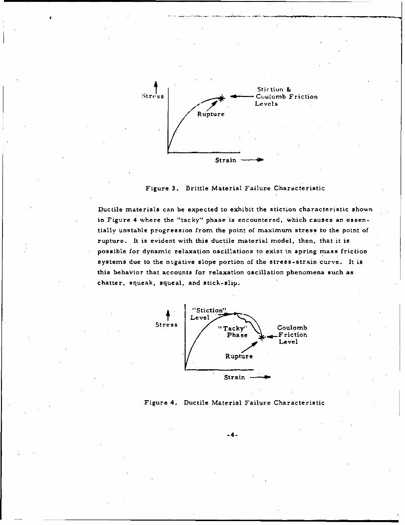
4 Stiction &
tress ----- Cuulomb Friction, // Levels
Rupture
Strain
Figure 3. Brittle Material Failure Characteristic
Ductile materials can be expected to exhibit the stiction characteristic shown
in Figure 4 where the "tacky" phase is encountered, which causes an essen-
tially unstable progression from the point of maximum stress to the point of
rupture. It is evident with this ductile material model, then, that it is
possible for dynamic relaxation oscillations to exist in spring mass friction
systems due to the n',.gative slope portion of the streSs-strain curve. It is
this behavior that accounts for relaxation oscillation phenomena such as
chatter, squeak, squeal, and stick-slip.
" "Stiction"
Level.Stress "Tacky" i Coulomb
Phase '4....Friction/Zr Level
Rupture
Strain
Figure 4. Ductile Material Failure Characteristic
-4-

It would seem too mruch to-expect ýthat the mechanism described' above
would apply equally well to both sliding and rolling friction, and yct it
apparently does. Up to this point we have not made a distinction between
sliding and rolling friction, and thisý was purposely done to imbue the idea
that solid friction encompasses both of these types of friction. ,The difference
between these types of friction may be explained simply 'by reference to
Figures 5 and 6.
Figure 5 shows, the case of sliding friction where the interface cohesively
bonded regions undergo principally shearing stresses. Thus, the inter-face
bond material properties that govern the sliding friction process are mostly
their shear properties.
FOP
External Force
Shear stresses in interface bonding regions
Figure 5. Sliding Friction
On the other hand, the case of rolling friction is illustrated in Figure 6
wherein the interface cohesively bonded regions are compressively stressed
on the front side of the contact area and are stressed in tension on the back
side. Thus, for rolling friction, tension and compression properties prin-
cipally govern the friction process.
Sliding friction, then, involves shear failure because it is the only
process by which continuous rupture can occur. Tensile failure would
separate the bodies at rupture and compressive failure would break one or both
of the bodies. Cutting of a solid material with a tool can be thought of as this
kind of process, i.e., continuous'shearing ru pture.
-5-

External Torque
Tensile stresses in back ~ "Comnpressive stresses, in frontpart of interface bond~ng part of interface bonding regionsregions
Figure 6. Rolling Friction
Rolling friction is seen to also involve continuous rupture, but the
friction-associated rupture, appears to be tensile in most engineering appli-
cations such As in ball bearings. Rolling mill crushers are an example of
the continuous rupture process that involves continuous compressive failure.
Ball bearings no doubt fail in compression when overloaded, but during
normal operation the compressive stresses developed. on the, front side of
the contact area merely helps establish the cohesive bond that must later be
broken in tension on the back side of the contact area.
There is a question whet-her stiction, per se, can be distinctly identi-
fiable in rolling friction. The author believes that it is not. This preconcep-
tion is based on the notion that the interface bond strain is distributed over
the area of contact where fracture occurs (i.e. , the back side where tension
failure proceeds) and thus an averaging of the strain over the stress-strain
curve apparently takes place.,
The phyrics of the continuous stress rupture process is not und 'erstood
but conjecture leads this writer to believe that an explanation perhaps lies in
Dorn's theory (References 4 and 5) that creep, leading to stress rupture,
occurs in thermally activatE~d deformation processes or perhaps vice versa,
i.e. , as in the friction-caused deformation process w,.hich induces thermal
-6-

activation and local interface heating. Thus, the back aide bond creep rates
being forced by rolling velocity are the result of contact bond energy of
activation and entropy of activation produced by rolling compression on the
front side. The entropy of activation is thus believed to be the thermal
energy generated by the rolling friction process.
-7-

III. A SIMULATOR FOR SLIDING FRICTIONIN DUCTILE MATERIALS
The process just described, coupled with Newton's second law, pro-'
vides a model of solid sliding friction that can be represented by the sche-
matic diagram of Figure 7. This process is simulated by the block diagram
of Figure 8 where the net force available to accelerate the mass is the dif-
ference between the component of the external force parallel to the contacting
surface elements and the frictional force. The time integral of the net force
produces the velocity * which is integrated to find the elemental displacement
Ax from the initial equilibrium position. This elemental displacement is
redefined each time the direction of motion changes. Thus, when relay R3
in the diagram is activated by positive velocity, contact R 3 1 + is closed, and
contact R1 is closed prior to fracture, which permits integration to obtain the
+Ax relative displacement from the equilibrium position. When A.x reaches
x
'F`Ftang
Mass9, M
Ffriction
Figure 7. Dynamical Sliding' Friction Model
-8-

Uo
"a9
f cc
a. 0
L.2
LLi
LLL

fpf (assuming Axpb = 0), relay Ri is actuated, corresponding to fracture of
the contact bond, and the RI relay contact is opened thereby holding the value
of Ax on the integrator output. The fracture level of stress is then filtered
and multiplied by the contact area to obtain the net solid frictional force.
This force is obviously constant a3 long as k is positive and fracture has
occurred and is seen to correspond to the coulomb friction force.
If the applied force is reversed, k will change sign causing closure of
the R3 1 - contact. The R. contact will be closed, because tn will be positive,
correspinding to the establishment of the contact bond in the reverse direc-
tion. Thus, Ax will start to decrease from the value Ax = 4pf.
For x < 0, the R 3 3 + contact is opened and the R 33- contact closed so
that the friction level is set by the negative stress function 0"n. At the instant
of i reversal, c" = a due to the fact that a' is slaved to a by servo action;n p n pi.e., a n is compared to a p and any error is integrated to bias the input to the
negative stress function generator so as to drive the error between a-n and u'n pto zero. It may be noted that the positive stress function 0' is slaved to a"npn
for negative motions (i < 0) when sn in being read out to generate Fsolid.Relay switching with contacts R 3 2 'and R 3 3 is necessary to implement the
load removal characteristic shown in Figure 2. A filter with time constant
TF is added in the simulator to filter the R33 switch transients.
The net friction level is proportional to the load normal to the surface
in the case of static and coulomb friction, The exact mechanism of this
relationship is not understood fully and so, for the purposes of simulation,
it is assumed that the contact or bond area is proportional to the force normal
to the surface. Thus, A in the block diagram represents this force.preload
By multiplying the streas by area to obtain the frictional force, it
becomes possible' to introduce friction noise in what is believed to be a
realistic manner. The area noise, Anoise, is that contact area variation
produced by surface irregularities. It is a stochastic function of the variable
x and so a random function generator is shown that generates A noise (W) for
lhin I)urpo-se.

Laminar (viscous) and turbulent friction terms have been included
in the simulator block diagram for generality.. Laminar friction is assumedto be proportional to velocity, and turbulent friction is assumed to be pro-
portional to the square of velocity.

IV. A SIMULATOR FOR SOLID FRICTIONIN BRITTLE, MATERIALS
An alternate and much simpler friction simulator than that in Figure 8
is shown in Figure 9. This simulator should be applicable to rolling friction
and brittle dry sliding friction and perhaps to lubricated sliding friction
involving ductile materials. In this simulator, advantage is taken of the
observation that the friction stress function, f, being a function of displace-
ment, x, can be differentiated with respect to time
df df dx
and the result integrated to generate f. It is observed that f' is easily found
as a function of x. The simulation block diagram, however, shows f' being
generated using a function generator with f as the input. Thus it is required
to determine f' as a function of f. This determination can be illustrated with
a few examples.
Example I
Assume fWx) kx, -x 5 <x <xx
or f(x) W = kx, JxZ >is
Then f = k, -x5 <x <x , -kx• <f < kx
= 0, IfI > kx
-12-

II.
4- izEi
4t- 13-
S°4
o0
tt ,f -h
-13-

These relations are illustrated below:
o4
ftkx -
__ kj
Example 2
Assume fx) = P1 e - x) ,x > 0
Then ' = e
= Pa-ef f >0f' >0
f-- P
Example 3
Assume instead of a linear f, vs f relation as in Example 2., a square
law relation
= ylf-f 0 2
-14-

This is easily integrated to obtain
i
The constant of integration is determined by knowing that the friction f = 0
when at rest atx= 0. Thus, c = i/y f0 and we obtain
Yf2f = yf 0 x... (T r f x T I)
These relations are illustrated below.
- f
fofdxo
Referring to Figure 9, the time derivative of the friction function f is
integrated to obtain f(x). Starting at x 0, f = 0, and for * > 0, it may be
seen that f(x) asymptotically approaches f0 as indicated below. When *
changes sign and the direction of motion changes, relay R 3 is actuated thereby
switching R3 1 . This changes the sign of f from + to - causing the value of
f, to change from f' (f) to a value fP (-f). This behavior is exhibited for all
levels of friction.
-15-
S...

f i u afa(fe x reversal
p e l t e t e r h p o i n t
f'(o) f'(o
ff'(f 0 )
0 0
An illustrative example of the model is the case of the freely rolling
ball on a flat surface with an initial velocity. The friction-displacement and
phase plane trajectories are shown below.
-16-
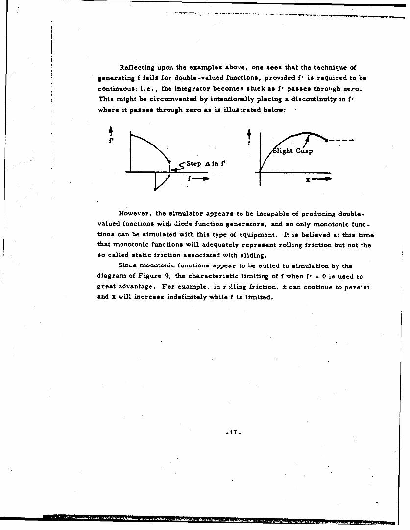
Reflecting upon the examples above, one sees that the technique of
generating f fails for double-valued functions, provided fV is required to be
continuous; i.e. , the integrator becomes stuck as P' passes throu~gh zero.
This might be circumvented by intentionally placing a discontinuity in Vwhere it passes through zero as is illustrated below:
fg f
light Cusp
Step A in f,
f __4W Ix -4w
However, the simulator appears to be incapable of producing double-valued functions wirih diode function generators, and so only monotonic func-
tions can be simulated with this type of equipment. It is believed at this timethat monotonic functions will adequately represent rolling friction but not theso called static friction associated with sliding.
Since monotonic functions appear to be suited to simulation by thediagram of Figure 9. the characteristic limiting of f when f' 0 is used to
great advantage. For example, in r lling friction, *can continue to persistand x will increase indefinitely while f is limited.
-17-

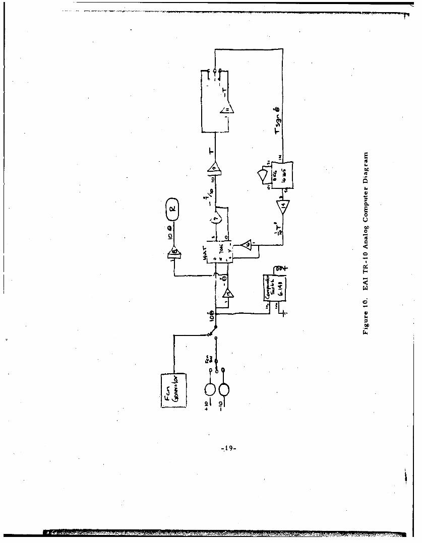
V. SIMULATION R.ESULTS
A computer simulation of the simple model shown in Figure 9 was
implemented on an EAI TR-10 Analog Computer. The computer diagram
used is shown in Figure 10. Experimental data on a 60 mm bore Class 7
super precision 12-degree contact angle ball bearing with a 60 lb preload
was obtained by I-iro Shibata in the Aerospace Guidance and Control Laboratory
under the direction of Dave Griep. The experimental apparatus was set
up to drive the inner race of the ball bearing with a torquer whose current
was closed-loop servo-controlled to maintain highly accurate angular rates
which were measured with a gyro. The rate could be commanded, and
several tests were run with sinusoidal input rates. Bearing friction torque
was measured with a high accuracy Micro Gee position table adapted for
use as a torque measuring instrument. The measured friction torque and
gyro rate were recorded for four sinusoidal inputs to the rate drive servo.
The frequencies of these four runs were 0.5, 0. 1, 0.04, and 0.01 cps and
the angular rate amplitude was 0. 125 deg/sec in all four of these runs. The
recorder trace data was reduced, and friction torque Tf was plotted versus
angular displacement E which was computed using gyro data. The slopes of
the resulting curves were measured to obtain dTf/d9 information that could
be plotted versus Tf. The resulting test data is in Figure 11. Also shown
in the figure is the function approximated by the DFG in the TR-10 simulation.
It is interesting to note that experimental data indicates a square law
T' vs T relation. An empirical curve fit equation is also shown in Figure 1I
for this data. The empirical equation determined is:
dT=y(T -T 0 )2
whe r yT0 -- 36 in-oz/deg
To 6 in-oz
y= 1.0 (in-oz-deg)"
-18-
LIL

I , I
j _ ___________.... ___________ _...__..L, . ....
o9"- I " -- -
~_20
-- ,
"II
• -. ,-7..
Sn- -I- .~ f -~ 1)
I-.= -
" ' ' : ;
I- I ,
-Z0-
t4 ..
• .•-20-
iA

Simulation runs were made employing constant rate 6 inputs to the
simulator and other input functions such as sawtooth and sine functions.
Because it had been expected that the experimental- test results could be
interpreted according to the coulomb friction model, the data obtained from
the tests were plotted as friction torque versus angular rate. Accordingly,
several runs were made simulating the tests and the computer torque and
rate variables were recorded on an x-y plotter.
Results of the simulation are shown in' Figure 12. For comparison,
the experimental data are shown for half of a cycle for each irequency.
The validity of the model presented here can hardly be disputed on the
basis of this and other comparisons that have been made. The comparison
of Figure 12 shows that the simulation faithfully reproduces the unexpected
hysteresis characteristic first noted by H. Shibata. It is apparent by exam-
ination of Figure 12 that, as frequency is lowered, the step-like nature of
coulomb friction is, approached with the width of the hysteresis loop reduced.
In the limit, as frequency goes to zero, the step-like discontinuity is
approached and the hysteresis loop, width will vanish. Thus wim see that
coulomb friction is a special case of the more general solid friction modelpresented here.
It is interesting to speculate that the friction model developed here isapplicable to magnetic and other forms of hysteresis. Physical processes
that exhibit hysteresis are now believed to be characterized by the functional
dependence of the ordinate variable on the time integral of the abscissavariable. The resulting functions behave as a brush whose bristles mastbend as the brush moves in one direction and then flop or bend in the opposite
direction if, the motion is reversed.

0 o 1o0cps0 04 c PI
.9.
4 700-
SI-.. .... o/I
A NUL L LATE IPa°"ec. -
-015/ 0O.Ody • .. 0
Figure 12. Comparison of Simulator and Experimental Test Results
-22.
) VI. CONCLUSIONS
A general model for solid friction has been presented that has been
validated by ball bearing friction experiments data.
The heretofore unexpected hysteresis characteristic in rolling friction
found by Shibata and Griep was somewhat amazingly simulated by the simple
computer simulation over a wide frequency range.
Coulomb friction was found to be a special case of the general solid
friction model.
Static friction (stiction) is exhibited during sliding between ductile
materials.
Stiction does not occur in sliding between brittle (or well lubricated)
materials. It is speculated that stiction is rare or completely absent in
rolling friction.
Rolling friction involves a compressing/tensing process and sliding
involves a shearing process.
Solid friction is caused principally by contact bond stress and is quasi
static in character. Making and breakini of the contact bonds is dynamic and
governed by motion of the bodies driven by the external or inertial forces.
The friction model presented is believed to be related theoretically to
magnetic hysteresis and the simulator described can obviously be 'used to
simulate other forms of hysteresis.
The stochastic nature of various forms of friction is thought to enter
through the randomness of contact area variation and a seemingly plausible
way of including this in the simulation model is shown. However, the
accuracy of this representation has yet to be validated. Analog computer
random function generators are not available that directly produce functions
of variables other than time, and so a digital simulator might be more appli-
cable for this purpose.
23-

REFERENC ES
1. Polakowski, N. H., and Ripling, E. J., Strength and Structure ofEngineering. Materials, Prentice Hall, Englewood Cliffs,New Jersey, 19,66.
2. Rabinowicz, E., Friction and Wear of Materials, John Wiley,1965.
3. Korn, G., "A New Analog Computer Setup for Simulation of Staticand Coulomb Friction," Inst. & Control System (Sept 1962), pg 171.
4. Kennedy, A. J., Processes of Fatikue and Creep in Metals(pp 215-228), Oliver and Boyd, Edinburgh, 1962.
5. Am. Soc. Metals, "Creep and Recovery," (pp 225-283),Cleveland, 1957.
6. Bisson, E. B. and Anderson, W. J., Advanced Bearing Technology,NASA Doc SP-38, 1964.
-24-


![Model of contact friction based on extreme value statistics · Friction between solid bodies is an extremely complex physical phenomenon, acting on many scales [1–5]. Amonton claimed](https://img.dokumen.tips/doc/110x75/5fa734ad598d155083520380/model-of-contact-friction-based-on-extreme-value-statistics-friction-between-solid.jpg)