Embed Size (px)
Citation preview

ADVANCES IN MANUFACTURING SCIENCE AND TECHNOLOGY
Vol. 38, No. 3, 2014
DOI: 10.2478/amst-2014-0014
Address: Prof. Wit GRZESIK, Krzysztof ŻAK, PhD Eng., Opole University of Technology, Faculty of Mechanical Engineering, 45-271 Opole, 5 Mikołajczyka Str., e-mail: [email protected], [email protected]
FRICTION MODELLING IN METAL CUTTING
WITH INTEGRATED TOOL WEAR EFFECTS
Wit Grzesik, Krzysztof Żak
S u m m a r y
In this paper, friction in longitudinal turning operations when using chamfered uncoated ceramic tools is investigated. Both tool-chip and workpiece-tool interactions are integrated in the friction model. The values of three force components were consequently measured during tool wear tests at different cutting speeds they were used as input data for computing the friction and normal forces acting on the rake and flank faces and, as a result, for determining the relevant friction coefficients. It was observed that both friction coefficients are sensitive to tool wear progression depending on the cutting speed used. For comparison the values of friction coefficient were determined for orthogonal (2D) friction model. The 3D friction model was tested for the machining of spheroidal cast iron (SCI) using uncoated nitride ceramic inserts.
Keywords: friction, tool wear, metal cutting, silicon ceramic tool, spheroidal cast iron
Modelowanie tarcia w skrawaniu metali ze zintegrowanym wpływem zużycia narzędzia
S t r e s z c z e n i e
Prowadzono analizę tarcia w operacjach toczenia wzdłużnego z użyciem narzędzi z niepowlekanej ceramiki azotowej. W przyjętym modelu tarcia uwzględniono synergię oddziaływania na styku ostrze-wiór i przedmiot-ostrze. Wykonano pomiary wartości trzech sił składowych w czasie próby zużycia ostrza dla różnych wartości prędkości skrawania. Określane wartości użyto jako dane wejściowe do wyznaczenia wartości siły tarcia i siły normalnej, i w kolejności do wyznaczenia wartości określonego współczynnika tarcia. Stwierdzono, że współczynnik tarcia jest wrażliwy na przyrost zużycia narzędzia, zależnie od prędkości skrawania. W celu porównania wyznaczono wartości współczynnika tarcia dla ortogonalnego (2D) modelu tarcia. Weryfikację modelu 3D tarcia prowadzono dla skrawania żeliwa sferoidalnego z zastosowaniem niepowlekanych płytek ostrzowych z ceramiki azotowej.
Słowa kluczowe: tarcie, zużycie ostrza, skrawanie metal, narzędzia z ceramiki azotkowej, żeliwo sferoidalne
1. Introduction
Friction and tool wear are fundamental problems in machining research and
modeling because they govern such process inputs as cutting forces, cutting
energy, heat generation, and surface quality. The present knowledge of friction

6 W. Grzesik, K. Żak
in metal cutting seems to be insufficient to accurately model mechanical,
thermal and tribological phenomena. Nowadays, the determination of the friction
coefficient is generally based on the 2D orthogonal cutting model and
Coulomb’s law [1, 2]. In addition, other models based on adhesive interactions
between the tool and the workpiece [3, 4] or a strain-hardening behaviour of the
contact are proposed [5]. It is important that FEM-based cutting simulations
using an inappropriate friction coefficient can generate more than 50%
differences in cutting forces and the tool-chip contact length [6, 7]. On the other
hand, the real cutting process is 3D in nature and consequently needs oblique
cutting using cutting tools with defined inclination angle s to be considered [1].
Typical values of inclination angle for commercial turning tools are small in the
range of s = –6 to –7 but for milling cutters, helical drills, broaching and
shaving tools it is often in the order of tens of degrees. The problem becomes
complex when using ceramic and CBN cutting inserts with negative rake angles
for the chamfer in the range of –20 to –30, so as to protect cutting edges
against premature failure [8, 9]. The problem is that the inclination and rake
angles are the factors which change the components of the resultant cutting
force. The third important factor is the sliding velocity which changes normal
and shear loads [3, 10]. As a result, the friction which is defined as the
relationship between normal force and friction force on the active parts of the
cutting tool is changed as well [11, 12]. Previous studies on wear-modified
friction [13, 14] indicated that for machining of spheroidal cast iron (SCI) with
CBN tools, friction changes correspond to tool wear evolution Moreover, it was
revealed in these studies that distinctly higher passive and feed forces occur in
longitudinal turning with worn CBN tools. This paper proposes an integrated
friction model for non-orthogonal cutting with chamfered fresh and worn Si3N4
ceramic tools.
2. Mechanistic modelling of friction in 3D cutting
2.1. Transformation of cutting forces
The forces acting on the rake and flank faces of the insert tip are presented
in Fig. 1. Firstly, as shown in Fig. 1a, the resultant force F in the xyz coordinate
system is resolved into three components- cutting Fz, feed Fx and passive (thrust)
Fy forces. Secondly, the lmn coordinate system in which the l axis is parallel to
and m-n plane is perpendicular to the cutting edge is introduced, so Fl, Fm and Fn
components characteristic for oblique cutting are specified. According to the
geometrical summation of forces in the Cartesian system:
x y z l m nF F F F F F F (1)

Friction modelling in metal cutting ... 7
a)
b)
Fig. 1. Definition of coordinate systems (a) and forces acting
on the cutting wedge (b)
As shown in Fig. 1a, the lmn system is obtained by rotating the xyz system
by the s angle around the x axis firstly and secondly around the y axis by the
normal rake angle n.
Hence, the transformation of force components from the xyz coordinate
system to the lmn system using two unit rotating matrixes [TM]x and [TM]y [13]
is given by Eqn. (2).
cos 0 sin
sin sin cos sin cos
cos sin sin cos cos
n x xn n
l y s n s s n yx y
s o s s nm z z
F F F
F TM TM F F
F F F
(2)
Fn (F
Fx
n′
FN
F
Fz∙coss
Fm (FN
n
n

8 W. Grzesik, K. Żak
By solving matrix Eqn. (2) one obtains three equations which determine
components Fl, Fm and Fn in terms of the measured Fx, Fy and Fz forces, as
follows:
F l=− F x sin λssin γn +F y cos λs− F zsin λs cosγn (3.1)
Fm=F x cos λssin γn+F y sin λs+F z cos λscos γn (3.2)
F n=F x cos γn− F zsin γn (3.3)
It can be seen in Fig. 1b that the friction force on the rake face obγF is equal
to Fn and the normal force obγNF is equal to Fm. On the other hand, the friction
and normal forces acting on the flank face are equal to
cos sinα z n x nF = F α F α (4.1)
sin cosαN z n x nF = F α +F α (4.2)
In the next step the friction and normal forces were utilized to calculating
the friction coefficients related to the rake and flank faces.
2.2. Determination of friction models
When the friction force on the rake face (Fn) and the normal force (Fm) are
determined using a set of Eqns. (3.1)-(3.3), and forces F and FN acting on the
flank face are calculated by means of Eqns. (4.1) and (4.2), the average friction
coefficients for the non-orthogonal (oblique) cutting related to the rake and flank
faces are as follows:
obγ n
γ obobγN m
F Fμ = =
F F (5.1)
ααob
αN
Fμ =
F (5.2)
On the other hand, the friction coefficient for orthogonal cutting is equal
to [1]:

Friction modelling in metal cutting ... 9
1tg tg zo o
x
F
F
(6)
3. Experimental Procedure
3.1. Characteristics of machining process
Turning trials and wear tests were performed on the bars made of
spheroidal cast iron, EN-GJS-500-7 grade [15], using a CNC turning center.
Uncoated Si3N4 ceramic cutting inserts, CC6090 grade (Sandvik Coromant),
denoted by symbol TNGA 16 04 08T02520 GC1690 which were clamped in
PTNGR 2020 –16 tool holder were selected. The optical image of the insert
corner with characteristic chamfer dimensions is presented in Fig. 2.
Fig. 2. Geometry of the cutting tool insert used – r= 0.8 mm,
bn = 0.20 mm, nc = 20
Nominal effective rake angle was equal to oe = –6, the chamfer angle was
equal to nc = –20 (the effective rake angle at the chamfer was nce = –26) and
the tool cutting edge angle r = 90. The chamfer width was equal to 0.2 mm as
shown in the wedge cross-section in Fig. 2. The following cutting parameters
were selected: constant depth of cut ap = 0.8 mm and a feed rate of 0.08 mm/rev
and 0.12 mm/rev, and a variable cutting speed of 100, 160, 240, 320, 400 and
480 m/min. Relatively small values of feed rate in conjunction with a large
chamfer width of 0.2 mm guarantee that the chip-rake contact is concentrated on
the area of chamfer. In consequence, this fact allows relating all calculations of
forces acting on the rake face to the chamfer angle (in Eqns. (3.1)-(3.3) n = nce).
3.2 Measurements and visualization techniques
Three components Fz, Fy and Fx of the resultant cutting force (Fig. 1a) were
measured using a measurement system equipped with a Kistler 9257A
piezoelectric dynamometer and a Kistler 5070 signal amplifier. The measured
r
bn
nc

10 W. Grzesik, K. Żak
data were recorded using a DasyLab v9.0 data acquisition program.
Measurements of the wear scars on the flank face and visualizations of worn tips
were carried out on a Leica optical microscope equipped with a CCD camera.
Image processing was performed by means of an IM1000 program.
Examinations of worn corners were carried out using a Hitachi S-3400N SEM
microscope.
4. Experimental results and discussion
4.1. Measurements of tool wear
In this study the nose wear VBC was measured in the post-process mode
keeping the time intervals between several to dozens of seconds. An exemplary
SEM image of the worn Si3N4 tip is presented in Fig. 3. Based on VBC data
recorded the wear curves were drawn as shown in Fig. 4. The critical value of
nose wear VBC was assumed to be about 0.3 mm.
Fig. 3. Exemplary SEM image of tool wear
in the corner area
For instance, Fig. 3 shows the configuration of worn TiN/Si3N4 tip after
cutting test performed with the cutting speed of 400 m/min. In this case, the
worn zone was visualized using SEM technique. As shown in Fig. 3 the crater
wear is developed on the chamfered rake face which, in turn, changes
tribological conditions in comparison to the initial ones. Fig. 4 shows the
progress of the flank wear in the corner zone “C” depending on the cutting
speeds applied. Evidently, the time required to achieve the critical value of VBC
wear indicator is a function of cutting speed. In general, the tool life is rather
short and for instance for the medium cutting speed of 240 m/min it is about 2
min (the cutting length is about 480 m).
0
0.05
0.1
0.15
0.2
0.25
0.3
0.35
0 2 4 6 8 10 12 14 16
Fla
nk
we
ar
VB
C,
mm
Time, min
240
320
400
480
VBC
crater wear
flank wear
VBc
Co
rne
r w
ea
r
notch wear

Friction modelling in metal cutting ... 11
a)
b)
Fig. 4. Changes of tool flank wear VBc vs. time for different cutting
speeds and a feed rate of: a) 0.08 mm/rev, b) 0.12 mm/rev
4.2. Measurements of forces during wear tests
This study includes extended measurements of forces as a basic source of
the assessment of process instabilities during tool wear. The direct
measurements include three components Fz, Fy and Fx of the resultant cutting
force as shown in Fig. 5. In this case the forces were measured after the first 10 s
of cutting which roughly corresponds to the running-in period. It can be seen in
Fig. 5 that the value of the initial tool wear depends on the cutting speed used.

12 W. Grzesik, K. Żak
The first important effect which can be observed in Fig. 5 is that the radial force
Fy increases when the cutting speed and integrally tool wear increases. Based on
the measured values of Fz, Fy and Fx forces, the Fl, Fm and Fn components were
computed using a set of Eqn. 3.1-3.3. In order to illustrate the absolute changes
of the three componential forces Fz, Fx and Fy, their increments were determined
as the differences between force values measured at the beginning (fresh tools)
and the end (critically worn) of wear tests.
a)
b)
Fig. 5. Values of cutting forces and tool wear progress after 10 s cutting time:
a) for feed rate f = 0.08 mm/rev, b) for feed rate f = 0.12 mm/rev
The comparison of the increments of Fz, Fy and Fx forces during tool wear
shown in Figs. 6 and 7 reveals that they change in a specific manner depending
on the feed value. For the lower feed rate of 0.08 mm/rev tool wear causes that
the increments of the feed force Fx are the highest ones starting from the cutting
speed of 160 m/min. In contrast, the increments of the cutting force Fz are the
lowest ones, which additionally decrease when the cutting speed increases up to
0
0.05
0.1
0.15
0.2
0.25
0.3
0.35
0
50
100
150
200
250
300
350
400
450
500
100 160 240 320 400 480
Fla
nk w
ear
VB
c,
mm
Fo
rce,
N
Cutting speed vc, m/min
Fz Fy Fx VBc
0
0.05
0.1
0.15
0.2
0.25
0.3
0.35
0
50
100
150
200
250
300
350
400
450
500
100 160 240 320 400 480
Fla
nk w
ear
VB
c,
mm
Fo
rce,
N
Cutting speed vc, m/min
Fz Fy Fx VBc

Friction modelling in metal cutting ... 13
480 m/min. According to Fig. 7, showing the increments of the force
components Fz, Fy and Fx for the higher feed rate of 0.12 mm/rev, the most
important is the increment of the passive (radial) force, which visibly overcame
the increments of the feed force Fx documented previously in Fig. 6. It should be
noted that in both these both cases the value of VBc indicator was roughly kept
between 0.25 and 0.3 mm. This fact evidently confirms that the wear process
causes that the cutting performed with the chamfered Si3N4 ceramic and CBN
tools can be considered to be the oblique cutting [13]. The maximum increase
of the Fx force determined for the cutting speed of 400 m/min is approximately
of 500%. This fact can be explained in terms of intensive notch wear developing
in the vicinity of the secondary cutting edge (exemplarily see SEM image in
Fig. 3).
Fig. 6. Comparison of increments of cutting forces for worn tools
and different cutting speeds keeping feed rate of 0.08 mm/rev
Fig. 7. Comparison of increments of cutting forces for worn tools
and different cutting speeds keeping feed rate of 0.12 mm/rev
0
0.05
0.1
0.15
0.2
0.25
0.3
0
50
100
150
200
250
300
100 160 240 320 400 480
We
ar
ev
olu
tio
nV
Bc,
mm
Fo
rce
inc
rem
en
t, N
Cutting speed vc, m/min
Fz Fy Fx VBc
0
0.05
0.1
0.15
0.2
0.25
0.3
0
50
100
150
200
250
300
100 160 240 320 400 480
We
ar
ev
olu
tio
nV
Bc,
mm
Fo
rce
inc
rem
en
t, N
Cutting speed vc, m/min
Fz Fy Fx VBc

14 W. Grzesik, K. Żak
4.3. Determination of friction on the rake
and flank faces during tool wear
It is obviously known in the tribology of the metal cutting process that the
friction coefficient can exceed 1 distinctly especially at the flank face of
uncoated HSS and carbide cutting tools. For instance, it is reported that due to
severe adhesion between the flank/rake face and the fresh surface of the
workpiece/chip the value of is 1-1.4 [16, 17]. Moreover, the contact
conditions at this part of the wedge have elastic character without the seizure
effect occurring at the rake face part adjacent to the cutting edge (Fig. 8a). This
tribological evidence is confirmed by photo-elastic method in Fig. 8b. It is
revealed that the shear stress on the flank face is visibly higher that the normal
stress (Fig. 8b). The cutting temperature of 400-500C characteristic for
machining SCI with ceramic tools is sufficient for the occurrence of severe
adhesion at the flank face [18, 19]. This fact corresponds well to the changes of
the friction coefficient at the flank face presented in Fig. 9 and 10.
a)
b)
Fig. 8. Distribution of friction coefficient on the rake face (a) by Poletika and
Uteshev (1), Andreev (2), Kattwinkel (3), Takeyama and Usui (4), Chandrasekaran
and Kapoor (5) [10] and contact stresses on the rake and flank faces (b) [20]
Figures 9 and 10 present the relevant changes of the friction coefficients
ob and obtained at the beginning and the end of the wear tests of Si3N4 tips
for a range of cutting speeds and two feed rates of 0.08 and 0.12 mm/rev
respectively. They were determined by means of Eq. 5.1 using force values
specified in Fig. 5-7. For comparison, relevant changes of friction coefficient o
are computed for the simple orthogonal model using Eqn. 6.
1 2 3 4 5 6
0
O
nStress
Str
ess

Friction modelling in metal cutting ... 15
It is clear from the plots ob and o vs. cutting speed presented in Fig. 9
and 10 that the coefficient of friction on the rake face is more sensitive to the
cutting speed variations than the friction coefficient on the flank face. However,
differences between values of friction coefficient obtained for fresh (unworn)
(Fig. 9) and worn (Fig. 10) cutting edges can be related to different normal loads
determined by two mechanical models considered. This is because the
increments of the radial force Fy are the highest ones at the end of wear tests, as
shown in Figs. 6 and 7.
a)
b)
Fig. 9. Comparison of values obtained for orthogonal and oblique cutting
models for fresh cutting insert: a) f = 0.08 mm/rev, b) f = 0.12 mm/rev
Similar variations of the coefficient of friction for ceramic materials are
documented in Refs. [21] and [22] respectively. In particular, the tendency of
to decrease with the wear progress can be related to the thermal effect occurring
visibly at the temperature above 400-500C [15, 22]. In the machining of
spheroidal cast iron with the cutting speed of 240-480 m/min, the measured
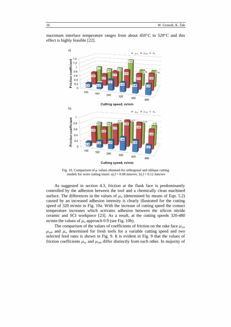
16 W. Grzesik, K. Żak
maximum interface temperature ranges from about 450C to 520C and this
effect is highly feasible [22].
a)
b)
Fig. 10. Comparison of values obtained for orthogonal and oblique cutting
models for worn cutting insert: a) f = 0.08 mm/rev, b) f = 0.12 mm/rev
As suggested in section 4.3, friction at the flank face is predominantly
controlled by the adhesion between the tool and a chemically clean machined
surface. The differences in the values of (determined by means of Eqn. 5.2)
caused by an increased adhesion intensity is clearly illustrated for the cutting
speed of 320 m/min in Fig. 10a. With the increase of cutting speed the contact
temperature increases which activates adhesion between the silicon nitride
ceramic and SCI workpiece [23]. As a result, at the cutting speeds 320-480
m/min the values of approach 0.9 (see Fig. 10b).
The comparison of the values of coefficients of friction on the rake face o,
ob and determined for fresh tools for a variable cutting speed and two
selected feed rates is shown in Fig. 9. It is evident in Fig. 9 that the values of
friction coefficients o and ob differ distinctly from each other. In majority of

Friction modelling in metal cutting ... 17
cutting tests, values of ob are of about five times higher than friction
coefficients computed for the classical orthogonal model represented by Eqn. 6.
It should be noted in Fig. 9 that at the beginning of wear tests, i.e. for
practically fresh Si3N4 uncoated ceramic inserts the differences between values
of o practically do not depend on the cutting speed used. On the other hand, the
variations of ob are relatively small at all cutting speeds. It is interesting to note
that for fresh tools the values of friction coefficients determined for rake and
flank faces are comparable (difference in same cases are about 0.1).
As shown in Fig. 10b, the wear of a Si3N4 ceramic insert causes the friction
coefficient to increase in comparison to the result obtained for fresh tools, and
this effect is more pronounced for orthogonal-based o which does not consider
changes of all three componential forces integrally. It can be noted that the
values of o approach 0.5 for the higher cutting speed. It is interesting to note
that for uncoated ceramic inserts similar behaviour of in comparison to ob
resulting from the wear progress is observed. This fact is in sharp contrast to
coated ceramic inserts for which at the end of the wear test performed with high
cutting speeds the values of are about 2 [24]. This fact evidently indicates
different tribological behaviour of the rake and flank faces during the tool wear
for uncoated and coated Si3N4 cutting tools.
5. Conclusions
The following original results were produced from this study:
A new 3D model of friction for non-orthogonal cutting, incorporating tool
wear is developed and compared with the 2D orthogonal model-based friction.
Substantial differences between the values of friction coefficient
determined for orthogonal and non-orthogonal cutting were revealed.
The values of friction coefficient determined for worn tools are higher
than those obtained for slightly worn tools (due to very rapid running-in
process). They are about 0.5-0.7 and 0.6-0.9 respectively.
The values of friction coefficient for the rake and flank faces are
comparable for fresh and worn tools.
The proposed methodology can be applied to determining the values of
friction coefficient for a selected time during the wear test.
References
[1] W. GRZESIK: Advanced machining processes of metallic materials. Elsevier,
Amsterdam 2008.
[2] M.C. SHAW: Metal cutting principles. Clarendon Press, Oxford 1989.

18 W. Grzesik, K. Żak
[3] F. ZEMZENI, J. RECH, W. Ben SALEM, Ph. KAPSA: Identification of friction
and heat partition model at tool-chip-workpiece interfaces in dry cutting of an
INCONEL 718 alloy with CBN and coated carbide tools. Advances in
Manufacturing Science and Technology, 38(2014)1, 5-21.
[4] W. GRZESIK: Experimental investigation of the influence of adhesion on the
frictional conditions in the cutting process. Tribology International, 32(1999), 15-
23.
[5] T.H.C. CHILDS: Friction modeling in metal cutting. Wear, 260(2006), 310-318.
[6] T. ÖZEL: The influence of friction models on finite element simulations of
machining. Int. Journal of Machine Tools and Manufacture, 46(2006), 518-530.
[7] P.J. ARRAZOLA, D. UGARTE, X. DOMINGUEZ: A new approach for the
friction identification during machining through the use of finite element modeling.
Int. Journal of Machine Tools and Manufacture. 48(2008), 173-183.
[8] H. REN, Y. ALTINTAS: Mechanics of machining with chamfered tools. Trans. of
ASME. Journal of Manufacturing Science and Engineering, 122(2000), 650-659.
[9] J.M. ZHOU, H. WALTER, M. ANDERSSON, J.E. STAHL: Effect of chamfer
angle on wear of PCBN cutting tool. Int. Journal of Machine Tools and
Manufacture, 43(2003), 301-305.
[10] M.F. POLETIKA: Contact Loads on the Active Parts of Cutting Tools (in Russian).
Mašinostroenie, Moscov 1969.
[11] W. GRZESIK: The mechanics of continuous chip formation in oblique cutting with
single-edged tool – Part I. Theory. Int. Journal of Machine Tools and Manufacture,
30(1990), 359-371.
[12] W. GRZESIK: The mechanics of continuous chip formation in oblique cutting with
single-edged tool – Part II. Experimental verification of the theory. Int. Journal of
Machine Tools and Manufacture, 30(1990), 373-388.
[13] W. GRZESIK, K. ŻAK: Friction quantification in the oblique cutting with CBN
chamfered tools. Wear, 304(2013), 36-42.
[14] W. GRZESIK, D. KOWALCZYK, K. ŻAK: A new mechanistic friction model for
the oblique cutting with tool wear effect. Tribology International, 66(2013), 49-53.
[15] W. GRZESIK, P. KISZKA, D. KOWALCZYK, J. RECH, Ch. CLAUDIN:
Machining of nodular cast iron (PF-NCI) using CBN tools. Proc. 4th
HPC Conf.,
Zurich, Procedia CIRP, (2012)1, 500-504.
[16] I.M. Hutchings: Tribology. Friction and Wear of Engineering Materials. Edward
Arnold, London 1992.
[17] W. GRZESIK: The influence of thin hard coatings on frictional behaviour in the
orthogonal cutting process. Tribology International, 33(2000), 131-140.
[18] W. GRZESIK, K. ŻAK: Mechanical, thermal and tribological aspect of the
machining process of nodular iron with coated carbide and ceramic tools. Advances
in Manufacturing Science and Technology, 33(2009)1, 31-43.
[19] W. GRZESIK, J. MAŁECKA, D. KOWALCZYK, P. KISZKA: Wear behaviour of
nitride ceramic cutting tools in the machining of nodular cast iron. Advances in
Manufacturing Science and Technology, 35(2011)2, 5-16.
[20] K. HOLMBERG, A. MATTHEWS: Coating Tribology. Elsevier, Amsterdam
1998.
[21] V.A. OSTAFEV: Physical fundamentals of the metal cutting process (in Russian).
Visša Škola, Kiev 1976.

Friction modelling in metal cutting ... 19
[22] W. GRZESIK: An investigation of the thermal effects in orthogonal cutting
associated with multilayer coatings. CIRP Annals Manufacturing Technology,
50(2001), 53-55.
[23] W. GRZESIK, J. MAŁECKA: Documentation of tool wear progress in the
machining of nodular ductile iron with silicon nitride-based tools. CIRP Annals
Manufacturing Technology, 60(2011), 121-124.
[24] W. GRZESIK, J. RECH, K. ŻAK: Determination of friction in metal cutting with
tool wear and flank face effects. Wear, 317(2014), 8-16.
Received in July 2014