Embed Size (px)
Citation preview
1
femetzhtlssns
flsaTtmccMmp
ambea
AT
2
8
Downloaded Fr
Ho-Hoon Leee-mail: [email protected]
Yi Liang
Del Segura
Department of Mechanical Engineering,Tulane University,
New Orleans, LA 70118
A Sliding-Mode AntiswingTrajectory Control for OverheadCranes With High-Speed LoadHoistingIn this paper we propose a sliding-mode antiswing control for overhead cranes. Theobjective of this study is to realize an antiswing trajectory control with high-speed loadhoisting. A sliding-mode antiswing trajectory control scheme is designed based on theLyapunov stability theorem, where a sliding surface, coupling the trolley motion withload swing, is adopted for a direct damping control of load swing. The proposed controlguarantees asymptotic stability while keeping all internal signals bounded. In associationwith a new antiswing motion planning scheme, the proposed control realizes a typicalantiswing trajectory control in practice, allowing high-speed load-hoisting motion andsufficient damping of load swing. The proposed control is simple for a real-time imple-mentation with high-frequency sampling. The effectiveness of the proposed control hasbeen confirmed by experiments. �DOI: 10.1115/1.2364010�
Introduction
Over the past two decades, considerable research has been per-ormed for the antiswing control of overhead cranes �1–11�. How-ver, the manual control of an experienced crane operator is stillore effective than a computerized antiswing control. An experi-
nced crane operator controls the crane along a typical antiswingrajectory that consists of an accelerating zone, constant-velocityone, and decelerating zone, frequently with high-speed loadoisting in the accelerating and decelerating zones. This implieshat the research in the antiswing control should address the fol-owing control criteria. First, the antiswing control should beolved as a trajectory control. Second, high-speed load hoistinghould be allowed in the accelerating and decelerating zones. Fi-ally, sufficient damping should be guaranteed for rapid suppres-ion of the load swing.
In this paper we propose a new sliding-mode antiswing controlor overhead cranes. An antiswing trajectory control scheme, al-owing high-speed load-hoisting motion, is designed based onliding-mode control �12�; the proposed control guaranteessymptotic stability while keeping all internal signals bounded.he proposed control provides a direct damping mechanism for
he load swing control. In association with a new antiswingotion-planning scheme �11�, the proposed control realizes a typi-
al antiswing trajectory control in practice, enabling high-speedontrol of load hoisting and sufficient damping of load swing.oreover, the proposed control is simple for a real-time imple-entation with easy gain tuning. The effectiveness of the pro-
osed control is shown with control experiments.The remainder of this paper is organized as follows. In Sec. 2,dynamic model of an overhead crane is described. In Sec. 3, aodel-based antiswing trajectory control scheme is designed
ased on sliding-mode control. In Sec. 4, the proposed control isvaluated through experiments. Finally, in Sec. 5, the conclusionsre drawn for this study.
Contributed by the Dynamic Systems, Measurement, and Control Division ofSME for publication in the JOURNAL OF DYNAMIC SYSTEMS, MEASUREMENT, AND CON-
ROL. Manuscript received October 23, 2004; final manuscript received April 25,
006. Assoc. Editor: Fathi H. Ghorbel.42 / Vol. 128, DECEMBER 2006 Copyright ©
om: http://dynamicsystems.asmedigitalcollection.asme.org/ on 10/06/2013
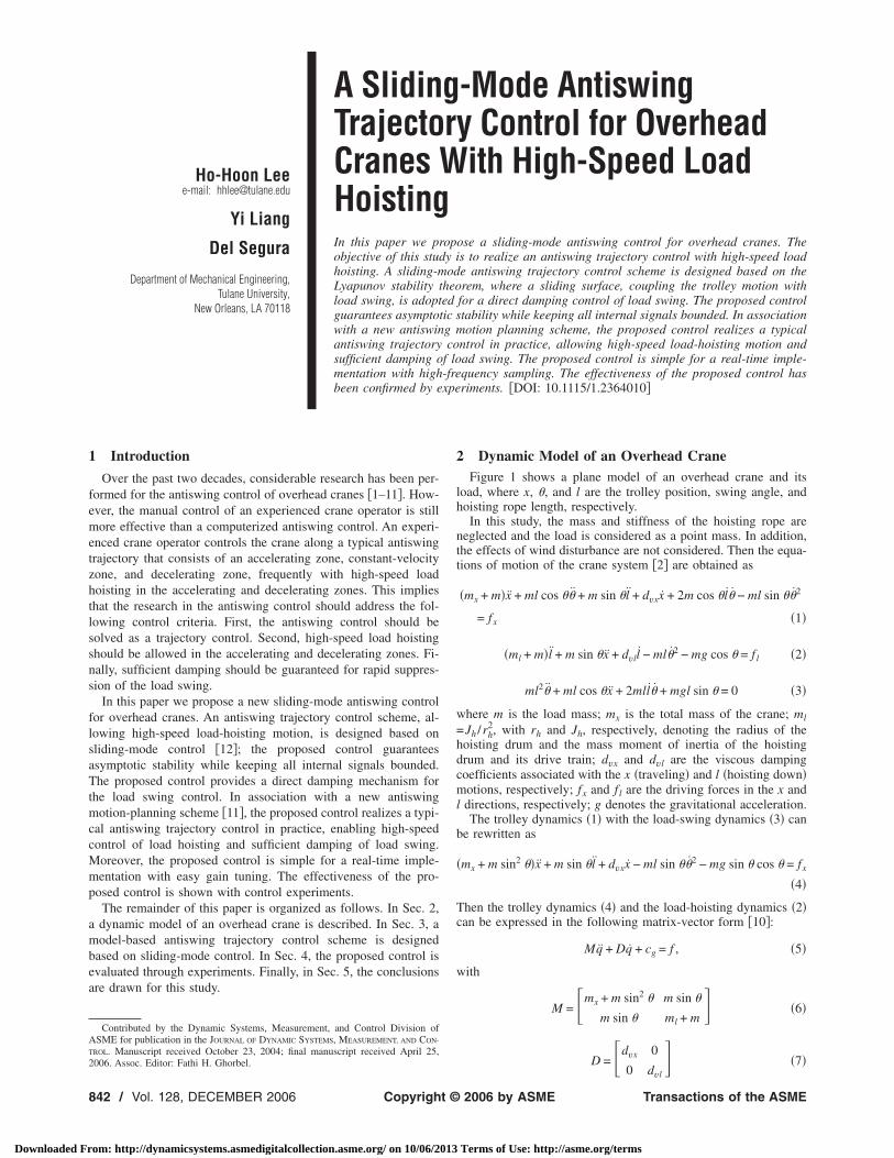
2 Dynamic Model of an Overhead CraneFigure 1 shows a plane model of an overhead crane and its
load, where x, �, and l are the trolley position, swing angle, andhoisting rope length, respectively.
In this study, the mass and stiffness of the hoisting rope areneglected and the load is considered as a point mass. In addition,the effects of wind disturbance are not considered. Then the equa-tions of motion of the crane system �2� are obtained as
�mx + m�x + ml cos �� + m sin �l + dvxx + 2m cos �l� − ml sin ��2
= fx �1�
�ml + m�l + m sin �x + dvll − ml�2 − mg cos � = f l �2�
ml2� + ml cos �x + 2mll� + mgl sin � = 0 �3�
where m is the load mass; mx is the total mass of the crane; ml
=Jh /rh2, with rh and Jh, respectively, denoting the radius of the
hoisting drum and the mass moment of inertia of the hoistingdrum and its drive train; dvx and dvl are the viscous dampingcoefficients associated with the x �traveling� and l �hoisting down�motions, respectively; fx and f l are the driving forces in the x andl directions, respectively; g denotes the gravitational acceleration.
The trolley dynamics �1� with the load-swing dynamics �3� canbe rewritten as
�mx + m sin2 ��x + m sin �l + dvxx − ml sin ��2 − mg sin � cos � = fx
�4�
Then the trolley dynamics �4� and the load-hoisting dynamics �2�can be expressed in the following matrix-vector form �10�:
Mq + Dq + cg = f , �5�
with
M = �mx + m sin2 � m sin �
m sin � ml + m� �6�
D =dvx 0
�7�
�0 dvl�2006 by ASME Transactions of the ASME
Terms of Use: http://asme.org/terms
w
3
bsus
wr
fibtrr
w
wn
oc
sA��fi�scy
J
Downloaded Fr
cg = �− sin ��ml�2 − mg cos ��
− ml�2 − mg cos �� �8�
here the state vector q and input vector f are defined as q�x l�T and f �fx f l�T.
Design of an Antiswing Trajectory ControlIn this section, an antiswing control scheme will be designed
ased on the trolley and load-hoisting dynamics �5�. The load-wing dynamics �3� will be incorporated into control design bysing a sliding surface that couples the trolley motion with loadwing.
First, a tracking error e�t� is defined as
e �ex el e��T „�rx − x� �rl − l� �r� − ��…T �9�
here rx, rl, and r� are the reference trajectories of x, l, and �,espectively.
ASSUMPTION 1. The reference trajectory r�rx rl r��T and itsrst and second time derivatives are assumed to be uniformlyounded and to be generated such that they are consistent withhe load-swing dynamics �3�. In addition, it is also assumed that� is not close to � /2, and that rl is not close to zero to avoid zeroope length �l=0� throughout the entire control.
Next, the following sliding surface s�t� is defined
s �sx sl�T �10�ith
sx = ex + kxex − kase� �11�
sl = el + klel + kli0
t
el dt �12�
here kx, kl, and kas are positive control gains and kli is a non-egative control gain.
Then the stability of the sliding surface s�t� is equivalent to thatf the trajectory error e�t� and velocity error e�t� under certainonstraints, which is described in the following lemma.
LEMMA 1. Consider an overhead crane whose dynamics is de-cribed by Eqs. (3) and (5), with its reference trajectory satisfyingssumption 1. Suppose that s and s are controlled such that sL� and �s � ��1 for some finite constant �1 and for all time t0. Then, under the constraints of ko�kas and kxkas�g for some
nite constant ko�1, the control guarantees that e, e, �0t el dt
L� if v�0��g. In addition, suppose that s and s are controlleduch that s, s→0 asymptotically as t→�. Then, under the sameonstraints, the control guarantees that e�t�, e�t�, �0
t el dt→0 as-¨
Fig. 1 Plane model of an overhead crane
mptotically as t→� if v�0��g, rx�t�=0, and r��t�=0 for all time
ournal of Dynamic Systems, Measurement, and Control
om: http://dynamicsystems.asmedigitalcollection.asme.org/ on 10/06/2013
t� to with some finite constant to�0, where
v�t� =1
2le�
2 + g�1 − cos �� � 0 �13�
with l�t��0. In this paper, � · � denotes the Euclidean norm ofargument vectors. The proof of Lemma 1 is given in theAppendix.
Remark 1. In the antiswing control, the rope length should bepositive �l�t��0� throughout the entire control, which requires theconstraints �s�t� � ��1 in Lemma 1 and Theorem 1 for some finitepositive constant �1. The antiswing control also requires � �� /2 for all time t�0, which is the region of stability for loadswing control. In this study, the region of stability is bounded byv�t��g, which implies � �� /2.
Finally, based on Lemma 1, a model-based sliding-mode anti-swing trajectory control is designed for an overhead crane, whichis described in the following theorem.
THEOREM 1. Consider an overhead crane whose dynamics isdescribed by Eqs. (3) and (5), and suppose that r, r, and r satisfyAssumption 1. Then, under the constraints of ko�kas andkxkas�g for some finite constant ko�1, the following sliding-mode control (14) guarantees that s, e, e, �0
t el dt�L�, and thats�t�→0 asymptotically as t→�, if �s�0� � ��1 and v�0��g forsome finite positive constant �1 that depends on the control gains,r, and l�0�. In addition, under the same constraints, the sliding-mode control (14) guarantees that e�t�, e�t�, �0
t el dt→0 asymp-totically as t→� if �s�0� � ��1, v�0��g, and rx�t�=0 and r��t�=0 for all time t� to with some finite constant to�0:
f = M�z + sgn�s�� + Dq + cg �14�with
z �rx + kxex − kase� rl + klel + kliel �T �15�
sgn�s� „x sgn�sx� l sgn�sl� …T �16�
sgn�s� �+ 1, for s � 0
0, for s = 0
− 1, for s � 0
�17�
where x and l are some finite positive constants.Proof. Consider the following Lyapunov function candidate:
VL�t� =1
2sTs � 0 �18�
Taking the time derivative of VL�t� along the trajectories of thedynamics �5� and the control law �14� yields
VL�t� = sTs = sT�z − q� = sT�z + M−1�Dq + cg − f�� = − x sx − l sl �19�
where M =MT�0 has been used in the derivation.
The definition of VL�t� and its time derivative VL�t� imply thats�t� is uniformly bounded and monotonically decreasing, and thats�t�→0 asymptotically as t→�, as a result of sliding-mode con-trol. The control input �14� to the crane system �3� and �5� is welldefined for 0� t��; therefore, s�t� is continuous and differen-tiable for 0� t��, thus resulting in s�L�. Since s�t� is mono-tonically decreasing, �s�0� � ��1 is equivalent to �s�t� � ��1 forsome finite constant �1�0 and for all time t�0. Then, as a con-sequence of Lemma 1, the proposed control guarantees that e, e,�0
t el dt�L�, and that e, e, �0t el dt→0 asymptotically as t→�,
since v�0��g and rx�t�=0 and r��t�=0 for all time t� to withsome finite constant to�0. Q.E.D.
COROLLARY 1. Suppose that the “sgn�s�” function in Theorem 1is replaced with a saturation function “sat�s ,�” defined in Eq.
�20�. Then, according to the results of sliding-mode control, theDECEMBER 2006, Vol. 128 / 843
Terms of Use: http://asme.org/terms
pvs
4
tmddsh=
8
Downloaded Fr
roposed control guarantees that the tracking errors are con-erged into a boundary layer whose thickness can be arbitrarilyet by a positive constant :
sat�s,� �s/ , for s/ � 1
sgn�s/� , for s/ � 1�20�
Experimental StudiesThe performance of the proposed control has been experimen-
ally evaluated in association with a new high-performanceotion-planning scheme �11�. For this experimental study, a two-
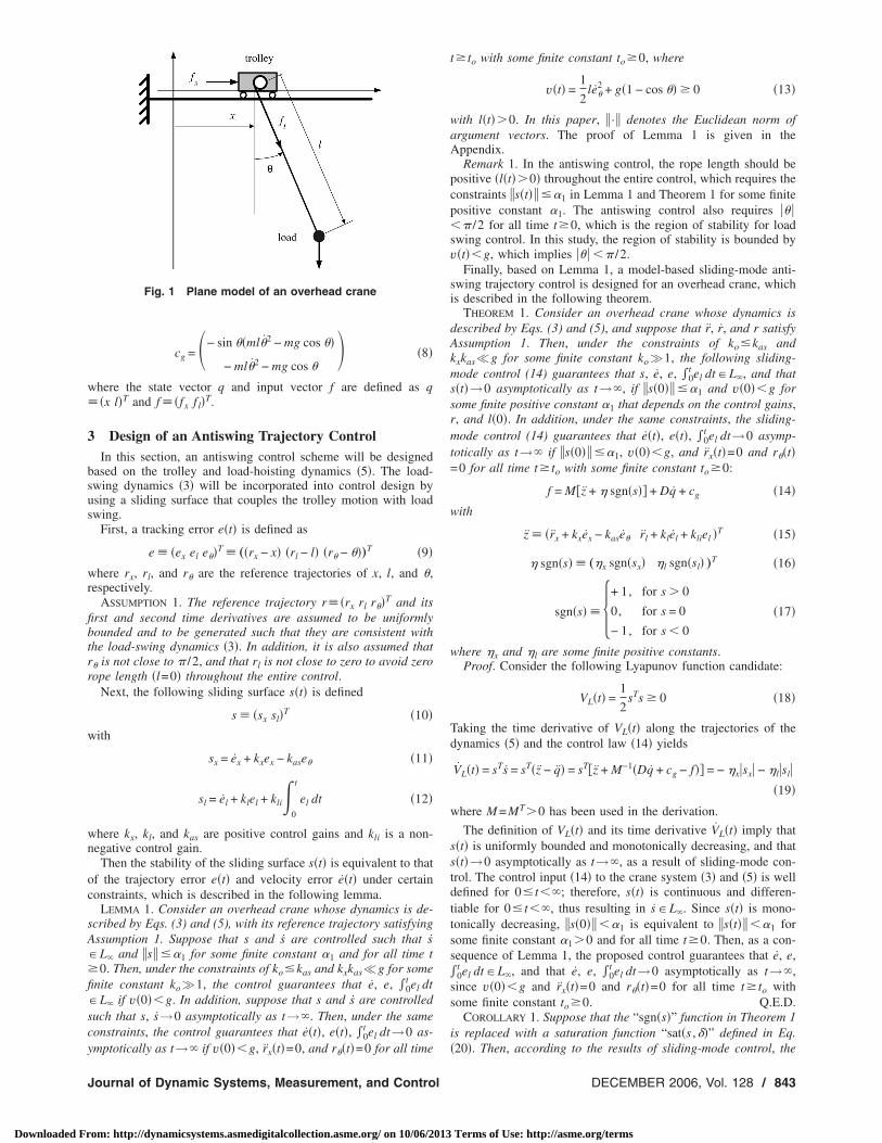
imensional prototype overhead crane, described in Fig. 1, wasesigned and built. The schematic diagram of its control system ishown in Fig. 2. The parameters of the prototype overhead craneave been estimated as m=15.6 kg, mx=36.2 kg, ml=1.7 kg, dvx2.5 kg/s, and dvl=0.2 kg/s, respectively.
Fig. 2 Schematic diagram of the control system
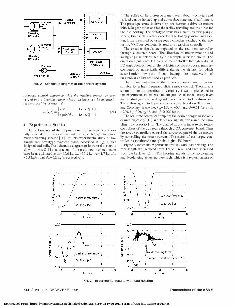
Fig. 3 Experimental resu
44 / Vol. 128, DECEMBER 2006
om: http://dynamicsystems.asmedigitalcollection.asme.org/ on 10/06/2013
The trolley of the prototype crane travels about two meters andits load can be hoisted up and down about one and a half meters.The prototype crane is driven by two harmonic-drive dc motorswith 1/50 gear ratio: one for the trolley traveling and the other forthe load hoisting. The prototype crane has a precision swing-anglesensor, built with a rotary encoder. The trolley position and ropelength are measured by using rotary encoders attached to the mo-tors. A VMEbus computer is used as a real-time controller.
The encoder signals are inputted to the real-time controllerthrough a counter board. The direction of motor rotation andswing angle is determined by a quadruple interface circuit. Thedirection signals are fed back to the controller through a digitalI/O �input/output� board. The velocities of the encoder signals arecomputed by numerically differentiating the signals, for whichsecond-order low-pass filters having the bandwidth of60� rad/s�30 Hz� are used as prefilters.
The torque controllers of the dc motors were found to be un-suitable for a high-frequency sliding-mode control. Therefore, asaturation control described in Corollary 1 was implemented inthis experiment. In this case, the magnitudes of the boundary layerand control gains x and l influence the control performance.The following control gains were selected based on Theorem 1and Corollary 1: kx=0.6, kas=1.3, x=0.4, and =0.01 for sx; kl
=200, kli=300, l=8, and =0.005 for sl.The real-time controller computes the desired torque based on a
desired trajectory �11� and feedback signals, for which the sam-pling time is set to 1 ms. The desired torque is input to the torquecontrollers of the dc motors through a DA converter board. Thenthe torque controllers control the torque output of the dc motorsby controlling the motor currents. The status of the torque con-trollers is monitored through the digital I/O board.
Figure 3 shows the experimental results with load hoisting. Therope length was reduced from 1.5 to 0.6 m, and then increasedfrom 0.6 back to 1.5 m. The hoisting speeds in the acceleratingand decelerating zones are very high, which is a typical pattern of
lts with load hoisting
Transactions of the ASME
Terms of Use: http://asme.org/terms
ctb
eTTae
dbsdmaf
ssttm
rmo3tss
itarm
5
dsktl
thtts
tc
J
Downloaded Fr
rane operation in industry. The trolley control force is noisy dueo the nature of the sliding mode control; in general, smalleroundary layers result in noisier control forces.
The overall control performance is excellent. All the trackingrrors are converged into their corresponding boundary layers.he steady-state trolley and hoisting errors are less than 0.005 m.he steady-state swing angle error is also less than 0.005 rad. Inddition, the performance of the proposed control is not influ-nced by trajectories.
The trolley control force should be negative when the trolley isecelerated, but it is positive throughout the entire control. This isecause the crane dynamics hardly affects the motor dynamicsince high-gear-ratio harmonic drives were used in the trolleyrive train. In this case, it is just sufficient to reduce the travelingotor torque to decelerate the trolley. The trolley tracking error
nd control force are nonzero in the steady state since the staticriction inside the harmonic drives is significant.
Considering the weight of the load mass, the hoisting forcehould be about −153 �=mg� N in the steady state, but the steady-tate hoisting force is almost zero, as shown in Fig. 3. This is dueo the high-gear-ratio harmonic drive used in the hoisting driverain. Under such high gear reduction, no torque from the hoisting
otor is required to balance the weight of the load mass.The prototype crane has a certain degree of mechanical inaccu-
acy associated with swing angle measurements. The swing angleeasurement error is a function of hoisting rope length as a result
f the misalignment of the swing angle sensor. Consequently, Fig.has significant swing angle errors with the load hoisted up since
he swing angle was initialized with the load hoisted down. Theteady-state swing angle error is due to the bending of the railtructure, as frequently observed in industrial applications.
The swing-angle measurement errors, due to the mechanicalnaccuracy, may result in significant trolley position errors sincehe trolley dynamics is coupled with the load swing dynamics. As
consequence, our future research will be concerned with theobustness of the overall control to the unavoidable swing-angleeasurement errors in application.
ConclusionIn this study, a new sliding-mode antiswing control has been
eveloped for the control of overhead cranes. The proposed anti-wing trajectory control guarantees asymptotic stability whileeeping all internal signals bounded. The coupled control of therolley motion and load swing allows a direct damping control ofoad swing.
In the experimental study, a “saturation function” was used forhe “sgn function” to prevent chattering. The experimental resultsave shown that all the tracking errors are converged into a presethin boundary layer with sufficient damping. The performance ofhe proposed control is little affected by the magnitude of hoistingpeed, hoisting ratio, and hoisting distance.
The proposed control guarantees an antiswing control along aypical antiswing trajectory in practice. In addition, the proposed
ontrol law is simple enough for a real-time implementation withournal of Dynamic Systems, Measurement, and Control
om: http://dynamicsystems.asmedigitalcollection.asme.org/ on 10/06/2013
high-frequency sampling. Consequently, it can be concluded thatthe proposed control has approached one step closer to a highlyproductive antiswing control of overhead cranes.
Appendix: Proof of Lemma 1�I� Equation �12� is rewritten as
el + klel + kli0
t
el dt = sl �A1�
which is equivalent to
eli + kleli + klieli = sl �A2�
where eli�0t el dt.
Since s= �sx sl�T, �s � ��1 implies sl ��1 for some finite con-stant �1��1. Then the differential equations �A1� and �A2� guar-antee el ��2 and el ��3 for some finite positive constants �2and �3.
There exists some finite constant �3 that depends on r and l�0�such that el ��3 guarantees l�t��0 for all time t�0. As a con-sequence, there exists some finite constant �1 that depends on r
and l�0� such that �s � ��1 implies l�t��0 and l�t� ��4 for somefinite constant �4. When sl→0 asymptotically as t→�, Eq. �A2�guarantees that el→0, el→0, and eli→0 asymptotically as t→�.
�II� The second part of the proof is identical to that of ourprevious study �10� and hence is omitted. Q.E.D.
References�1� Yu, J., Lewis, F. L., and Huang, T., 1995, “Nonlinear Feedback Control of a
Gantry Crane,” Proc. of ACC, Seattle, pp. 4310–4315.�2� Lee, H.-H., 1998, “Modeling and Control of a Three-Dimensional Overhead
Crane,” ASME J. Dyn. Syst., Meas., Control, 120, pp. 471–476.�3� Boustany, F., and d’Andrea-Novel, B., 1992, “Adaptive Control of an Over-
head Crane Using Dynamic Feedback Linearization and Estimation Design,”Proc. of the 1992 IEEE Conf. on Robotics and Automation, Nice, France, pp.1963–1968.
�4� Singhose, W., Porter, L., Kenison, M., and Kriikku, E., 2000, “Effects ofHoisting on the Input Shaping Control of Gantry Cranes,” Control Eng. Pract.,8, pp. 1159–1165.
�5� Collado, J., Lozano, R., and Fantoni, I., 2000, “Control of Convey-CraneBased on Passivity,” Proc. of ACC, Chicago, pp. 1260–1264.
�6� Kiss, B., Levine, J., and Mullhaupt, P., 2000, “A Simple Output Feedback PDController for Nonlinear Cranes,” Proc. of the 39th IEEE Conf. on Decisionand Control, Sydney, Australia, pp. 5097–5101.
�7� Yang, Y., Zergeroglu, E., Dixon, W., and Dawson, D., 2001, “Nonlinear Cou-pling Control Laws for an Overhead Crane System,” Proc. of the 2001 IEEEConf. on Control Applications, Mexico City, Mexico, pp. 639–644.
�8� Cho, S.-K., and Lee, H.-H., 2002, “A Fuzzy Logic Anti-Swing Controller forThree-Dimensional Overhead Crane,” ISA Trans., 41, pp. 235–243.
�9� Lee, H.-H., 2003, “A New Approach for the Anti-Swing Control of OverheadCranes with High-Speed Load Hoisting,” Int. J. Control, 76, pp. 1493–1499.
�10� Lee, H.-H., 2004, “A New Design Approach for the Anti-Swing TrajectoryControl of Overhead Cranes with High-Speed Hoisting,” Int. J. Control, 77,pp. 931–940.
�11� Lee, H.-H., 2005, “Motion Planning for Three-Dimensional Overhead Craneswith High-Speed Load Hoisting,” Int. J. Control, 78, pp. 875–886.
�12� Spong, M. W., and Vidyasagar, M., 1989, Robot Dynamics and Control, Wiley,
New York.DECEMBER 2006, Vol. 128 / 845
Terms of Use: http://asme.org/terms