Embed Size (px)
Citation preview

A shotcrete adhesion test system for mining applications
B. Seymour, L. Martin, C. Clark, M. Stepan and R. JackshaMining engineer, research mechanical engineer, mechanical engineer, engineering technician and
elctronics technician, National Institute for Occupational Safety and Health, Spokane, WA
R. Pakalnis, M. Roworth and C. CaceresMining engineers, University of British Columbia, Vancouver, BC
AbstractThe National Institute for Occupational Safety and Health (NIOSH) is conducting research to develop safe practices for the use of shotcrete as ground support in underground mines, particularly mines operating in weak host rock. As part of this research, a rugged, portable direct tensile test system was developed for measuring shotcrete adhesion strength in underground mines. During the development of this test system, more than 185 direct tensile tests were conducted with a common, commercially avail-able macro-synthetic fiber-reinforced shotcrete that was applied to concrete test panels using a dry mix process and machinery. The average bond strength of the shotcrete to the concrete substrate typically increased as a function of the shotcrete’s curing age, ranging from 0.44 MPa (64 psi) after one day of curing to 1.58 MPa (229 psi) after 90 days of curing. Adhesion strength increased markedly between one and three days of curing, reflecting a similar trend of increasing shotcrete tensile strength with cur-ing time. This robust direct tensile test system can improve mine safety by providing a reliable means of measuring shotcrete adhesion strength and also supplying important information about the quality of the applied shotcrete and the competency of the underlying rock.
IntroductionHistorically, a significant percentage of the injuries and
fatalities that occur in underground mines are caused by falls of ground (Fig. 1). To protect mine personnel from ground fall hazards, particularly in underground mines where the host rock is weak (RMR<40), research is being conducted by the National Institute for Occupational Safety and Health (NIOSH) to develop safe practices for the use of shotcrete as ground support.
Shotcrete is a specially blended, cement-based product that is pneumatically sprayed at a high velocity on the exposed surfaces of underground openings to provide ground support. In underground hard rock mines in the western U.S., shotcrete is generally used as an integral part of a ground support system consisting of multiple components. When ground conditions are poor and the host rock is weak, as in many of the underground gold mines in Nevada, extensive ground support is required. In these situations, shotcrete is typically applied in conjunc-tion with other ground support elements, such as bolts and mesh, but it is also used with spiling or cemented rockfill for extremely weak ground. A more complete explanation con-cerning the use of shotcrete in mechanized cut-and-fill stopes in Nevada is provided by Clark et al. (2010). In raveling and highly fractured ground, shotcrete is mainly used to provide surface support or skin control between the roof bolts, which serve as the primary ground support elements. By supporting the rock near the surface of the mine opening, shotcrete helps
prevent degradation of the anchorage for the other ground sup-port components and bridges the span between the rock bolts, thereby supporting the loose material that typically causes many of the small ground falls (Bernard, 2008). Shotcrete holds by adhesion, strengthens the rock by preventing relative movement at the shotcrete/rock interface and acts as a “super mesh” by providing a stiff retaining component with substantial bending or flexural capacity (Kaiser and Tannant, 2001).
When shotcrete is used as an integral part of a mine’s ground support system, it is important to know the strength proper-ties of the in-place shotcrete. Besides conventional strength parameters, such as the shotcrete’s flexural, compressive or tensile strength, the adhesion or bond strength of the shotcrete to the host rock must also be known, in order to adequately determine the shotcrete’s ability to support the immediate ground near the surface of the mine opening. Consequently, the adhesion strength of the shotcrete is a necessary parameter for ground support design.
Researchers have found that shotcrete applied in under-ground mines primarily fails in adhesion and that this initial debonding of the shotcrete from the underlying substrate is followed by a subsequent failure in flexure, as the shotcrete bends under the weight of additional loading from loose mate-rial (Fig. 2) (Barrett and McCreath, 1995; Holmgren, 2001). In another study, two basic types of shotcrete failure modes were identified through a mapping program at the Kiirunavaara Mine in Kiruna, Sweden (Fig. 3).

Laboratory tests in Sweden have indicated that the primary mode of failure of a good-quality shotcrete lining on hard rock is governed by adhesion (Holmgren, 2001). As discussed by Thomas (2009), the crown of an underground opening pres-ents the worst condition for shotcrete stability, because the shotcrete is loaded by its own weight from the moment it is sprayed. Further research has identified a more complete list-ing of possible shotcrete failure modes, particularly for cases where shotcrete is used in conjunction with roof bolts (Fig. 4).
Figure 1 — Underground metal mining injuries by accident class, 2004-2008 (MSHA).
Figure 2 — Flexural failure of shotcrete resulting from insufficient adhesion strength (after Kuchta, 2002).
Figure 3 — Two basic types of shotcrete failure modes. A: Fallout of only shotcrete, indicating poor adhesion; B: fallout of shotcrete and rock ,indicating zones of weak rock (after Malmgren & Svensson, 1999).
Figure 4 — Schematic of shotcrete loading and failure modes (after Morton et al., 2008; Barrett and McCreath, 1995).
Good bond strength depends on a number of factors, in-cluding proper surface preparation (Kuchta, 2002; Malmgren et al., 2005), adequate compaction between the shotcrete and substrate (Brennan, 2005) and also compatibility of the shotcrete with the host rock. Studies have indicated that the type of rock mineralogy can affect the bond strength (Hahn and Holmgren, 1979). For example, the adhesion of shotcrete to weak geologic formations, such as shale and mudstone, is frequently poor (Spearing, 2001). Experience has also shown that shotcrete bond strength can be poor in rock that is structurally weak in tension or, in other words, rock that is highly foliated, closely bedded or spalling (Kaiser and Tannant, 2001; Kuchta, 2002).
As mentioned by Spearing (2001), key elements of a shot-crete quality control program should include design compliance for bond, strength and thickness of the sprayed shotcrete. As a result, the ability to determine the bond strength or adhesion of the shotcrete is a key component of mine design and ground control methodology (Norwegian Concrete Association, 2007). A more thorough understanding of the in-place strength prop-erties of shotcrete, particularly the bond strength of shotcrete to the host rock, will lead to improvements in ground support
practices, thereby preventing falls of ground and reducing mine roof fall accidents.
BackgroundAdhesion strength of sprayed shotcrete is generally deter-
mined by a simple pull test known as the tensile bond strength test (Fig. 5). During this test, a direct tensile load is applied to a core drilled through the shotcrete into the underlying sub-

strate. As this load is gradually increased, the test core typically breaks or fails in tension. This tensile failure can occur in the shotcrete, at the bond surface (interface), in the substrate or at some combination of these locations. The adhesion or bond strength of the shotcrete to the substrate material is determined by measuring the maximum tensile load at failure. Depending on where the core breaks, the tensile strength at failure can represent either the actual adhesion strength of the shotcrete or an assumed lower limit of the adhesion strength. For example, if the core fails predominantly at the bond surface, then the bond strength or adhesion of the shotcrete to the substrate can be determined directly. However, if the core fails primarily in the shotcrete or substrate rather than at the bond surface (inter-face), then the adhesion strength of the shotcrete is inferred to at least exceed the measured tensile strength of the failed core.
Figure 5 — Simplified schematic of a tensile bond strength test (after ACI 506.4R, 2004).
Various test methods have been developed using this basic test configuration. For example, a standard test was established for the U.S. concrete industry, in which the direct tensile load is applied through a steel disk that is glued to the top of the shotcrete core (American Society for Testing and Materials, 2004; American Concrete Institute, 2007); an adhesion test method was developed in Sweden (SS 13 72 43), whereby a
direct tensile load is applied to a test core using a friction grip or core sleeve (Nordström and Grändås, 2005) and Canadian experiments have been reported in which shotcrete is applied over drilled pucks to determine adhesion strengths (Archibald et al., 1992). In the U.S., commonly specified direct tensile strength values for shotcrete applied to properly prepared con-crete substrates range from 0.69 to 1.00 MPa (100 to 145 psi) (Brennan, 2005). In Sweden, the bond strength is commonly required to be a minimum of 0.5 MPa (73 psi) between shot-crete and rock, 1.0 MPa (145 psi) between different shotcrete layers and 1.5 MPa (218 psi) for shotcrete applied to repair concrete (Nordström and Grändås, 2005). Values that have been typically reported for the adhesion strength of shotcrete applied to host rock in underground mines range from about 0.2 to 1.5 MPa (29 to 218 psi) (Barrett and McCreath, 1995; Malmgren and Svensson, 1999; Kuchta, 2003; Malmgren et al., 2005; Saiang et al., 2005; Morton et al., 2008).
Although a number of adhesion test methods have been developed, no universal procedure has been adopted or used extensively by the mining industry. Usually, the adhesion test equipment is unavailable or too expensive, complicated or fragile for extended use underground. Some of the test methods are not practical for typical mining conditions, because they require special surface preparation, gluing or curing time to allow the shotcrete to gain sufficient strength before a test can be conducted. As a result, the adhesion strength of shotcrete is seldom measured in underground mines, even though this strength parameter plays a major role in the stability of the shotcrete, particularly during the initial phase of curing.
As explained by Clark et al. (2010), it is important to measure the early-age strength characteristics of shotcrete in order to conservatively determine when the applied shotcrete is capable of providing ground support and, thus, when it is safe to re-enter a sprayed area. Adhesion strength is especially important during this initial phase of curing, because the shotcrete must be securely bonded to the host rock and held in place until the applied material can gain sufficient internal strength to resist further loading. Before an integrated, comprehensive design approach can be developed for the use of shotcrete as ground support, more complete information is needed regarding the shotcrete’s in-place strength properties, including the bond strength of the shotcrete to the rock.
Research and developmentTo develop a practical method of measuring shotcrete
adhesion strength in underground mines, NIOSH researchers conducted several series of direct tensile tests with shotcrete applied to concrete test panels. The focus of this investigation was to develop a suitable test method incorporating lightweight, portable, robust equipment, along with simple test procedures, so that mine personnel can measure the bond strength of the shotcrete that is used to support their underground workings. Concrete was used for these tests, to provide a substrate material of known quality and consistent strength properties, thus eliminating the influence of many confounding factors that would normally be present underground, such as varying rock type, geologic structure, discontinuities, blasting-induced fracturing, loose material, mud, dust and oil (Fig. 6).
Figure 6 — Average unconfined compression and splitting tensile strengths for the concrete substrate (n=36).
A commercial shotcrete mix commonly used in western hard rock mines was applied to the panels using a dry mix process and an Aliva-252.1 shotcrete machine equipped with a hopper and pre-dampener. For consistency, the same brand of macro-synthetic fiber-reinforced shotcrete (Superstick Shot-crete SCAPF) was used for all of the tests, along with similar
preparation methods and spraying procedures. Water was sprayed on the test panels to clean and moisten the concrete prior to applying shotcrete.
As explained by Seymour et al. (2010), five separate series of direct tension tests were conducted using the adhesion test fixtures or pull anchors shown in Fig. 7.
Figure 7 — Pull anchors investigated during the development of a direct tensile test system for determining shotcrete adhesion strength.
The first four series of tests were conducted with pull anchors that were embedded in the shotcrete as it was sprayed on the concrete test panels. These embedded test fixtures consisted of an expanded metal anchor and two different-sized metal washer anchors, which were held in place either manually or with a mounting grid while the shotcrete was applied.
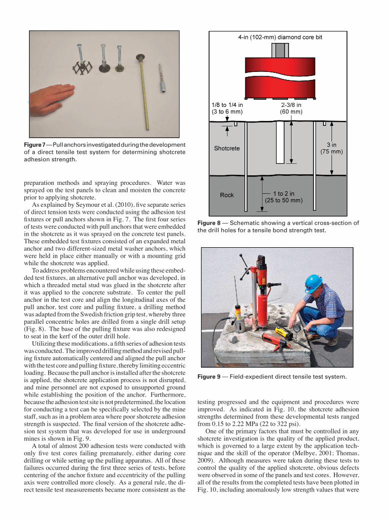
To address problems encountered while using these embed-ded test fixtures, an alternative pull anchor was developed, in which a threaded metal stud was glued in the shotcrete after it was applied to the concrete substrate. To center the pull anchor in the test core and align the longitudinal axes of the pull anchor, test core and pulling fixture, a drilling method was adapted from the Swedish friction grip test, whereby three parallel concentric holes are drilled from a single drill setup (Fig. 8).
Figure 8 — Schematic showing a vertical cross-section of the drill holes for a tensile bond strength test.
The base of the pulling fixture was also redesigned to seat in the kerf of the outer drill hole.
Utilizing these modifications, a fifth series of adhesion tests was conducted. The improved drilling method and revised pull-ing fixture automatically centered and aligned the pull anchor with the test core and pulling fixture, thereby limiting eccentric loading. Because the pull anchor is installed after the shotcrete is applied, the shotcrete application process is not disrupted, and mine personnel are not exposed to unsupported ground while establishing the position of the anchor. Furthermore, because the adhesion test site is not predetermined, the location for conducting a test can be specifically selected by the mine staff, such as in a problem area where poor shotcrete adhesion strength is suspected. The final version of the shotcrete adhe-sion test system that was developed for use in underground mines is shown in Fig. 9.
Figure 9 — Field-expedient direct tensile test system.
A total of almost 200 adhesion tests were conducted with only five test cores failing prematurely, either during core drilling or while setting up the pulling apparatus. All of these failures occurred during the first three series of tests, before centering of the anchor fixture and eccentricity of the pulling axis were controlled more closely. As a general rule, the di-rect tensile test measurements became more consistent as the
testing progressed and the equipment and procedures were improved. As indicated in Fig. 10, the shotcrete adhesion strengths determined from these developmental tests ranged from 0.15 to 2.22 MPa (22 to 322 psi).
One of the primary factors that must be controlled in any shotcrete investigation is the quality of the applied product, which is governed to a large extent by the application tech-nique and the skill of the operator (Melbye, 2001; Thomas, 2009). Although measures were taken during these tests to control the quality of the applied shotcrete, obvious defects were observed in some of the panels and test cores. However, all of the results from the completed tests have been plotted in Fig. 10, including anomalously low strength values that were

obviously caused by poor shotcrete quality.Table 1 provides a statistical summary of the average test
results organized in terms of test series and curing time.
Table 1 — Average adhesion test results.
Test
series
Curing
time,
days
Number
of tests
Adhesion strength, MPa
Standard
deviation,
MPa
Coefficient
of variation,
percent
Failure surface predominant
location, %
Mini-
mum
Maxi-
mum Range Avg Concrete Interface Shotcrete
1 7 8 0.97 1.96 0.99 1.56 0.31 20.0 0.0 12.5 87.5
1 14 4 0.74 2.22 1.48 1.28 0.65 50.9 0.0 0.0 100.0
2 7 46 0.18 1.67 1.49 0.88 0.34 38.6 4.3 34.8 60.9
3 3 28 0.15 1.41 1.25 0.79 0.29 36.7 14.3 21.4 64.3
4 3 15 0.80 1.59 0.78 1.21 0.25 20.6 13.3 26.7 60.0
4 7 15 0.94 1.69 0.74 1.41 0.19 13.8 53.3 6.7 40.0
4 14 15 1.07 1.71 0.64 1.40 0.19 13.7 53.3 26.7 20.0
5 1 9 0.19 0.91 0.72 0.44 0.28 64.0 0.0 22.2 77.8
5 3 9 0.67 1.43 0.76 1.13 0.28 25.1 0.0 33.3 66.7
5 7 9 0.95 1.53 0.58 1.22 0.20 16.0 0.0 11.1 88.9
5 14 9 0.32 1.96 1.64 1.30 0.49 38.0 0.0 33.3 66.7
5 28 9 0.75 1.67 0.92 1.46 0.31 21.0 0.0 11.1 88.9
5 90 9 1.25 1.99 0.75 1.58 0.22 14.2 0.0 0.0 100.0
Because direct tensile tests with a composite material are influenced by a number of factors, there is an inherent variability in adhesion test results, as indicated by the coefficient of variation values listed in Table 1. This innate variability demonstrates the im-portance of quality control measures, not only for casting the concrete panels, preparing the interface surface and applying the shotcrete, but also for operating the adhesion test equip-ment and consistently following well-defined test procedures.
As mentioned earlier, typical values reported for the adhesion strength of shotcrete in underground mines range from about 0.2 to 1.5 MPa (29 to 218 psi). Direct tensile tests conducted using the epoxy stud pull anchor gave adhesion strengths that were within a similar range, 0.19 to 1.99 MPa (28 to 289 psi).
Therefore, the developed test method appears to provide a credible means of measuring shotcrete adhesion strength.
Conducting a shotcrete adhesion testThis shotcrete adhesion test system consists of readily avail-
able and relatively inexpensive components, primarily a small stand-mounted core drill and a pulling unit equipped with a precision pressure gage (Figs. 9 and 11). The components are rugged and portable and they can be reliably used to measure the adhesion strength of shotcrete applied to the surface of an underground opening.
Figure 10 — Adhesion strength versus shotcrete curing time for various anchor configurations (n=185).
Figure 11 — Schematic of direct tensile test system for determining shotcrete adhesion strength.
Once a desired test site has been selected, a hand-operated rotary percussive drill is used to drill a 16-mm x 51-mm (0.625-in. x 2-in.) hole for anchoring the drill stand. After installing a 13-mm- (0.5-in.-) diameter threaded stud and expansion anchor in this hole, the drill stand is leveled and secured in

position. Three holes are then drilled from this single drill setup, ensuring that all of the holes are parallel and concentric (Figs. 8 and 12).
First, an 11.1-mm- (0.4375-in.-) diameter hole is drilled dry into the shotcrete, using a rotary percussive bit, to a depth of about 60 mm (2.375 in.), assuming a shotcrete thickness of 75 mm (3 in.). Next, the hole is cleaned, filled with a quick setting two-part epoxy adhesive and a 9.5-mm- (0.375-in.-) diameter pull anchor is inserted. After the epoxy has initially set or gelled (approx. 15 min), a 102-mm- (4-in.-) diameter diamond core bit is used to wet-drill a second hole through the shotcrete, to a depth of about 25-50 mm (1-2 in.) into the underlying substrate. Finally, a 127-mm- (5-in.-) diameter diamond core bit is used to wet drill a shallow kerf for seating the base of the pulling fixture, typically to a depth of about 3-6 mm (0.125-0.25 in.) depending on the irregularity of the shotcrete surface (Fig. 12).
Figure 12 — Parallel and concentric drill holes with extension rod connected to epoxied stud.
After the epoxy has fully set (30-60 min), a threaded exten-sion rod is connected to the pull anchor with a coupling nut and the pulling fixture is carefully placed over the core sample, with the base of its reaction ring positioned in the kerf of the outer drill hole. The hydraulic hose from the hand pump is then connected to the loading ram and the ram is cycled a few times to remove any extraneous air from the system. Next, a collet and a slip-on, quick-threading locknut are connected to the threaded extension rod to serve as a mechanical stop for the pulling fixture’s ram. To conduct a test, the pressure gage is zeroed and an increasing tensile load is applied to the core sample through a slow and steady movement of the pump handle until the core breaks. Test duration varies depending on the tensile strength of the test core (typically 30 sec to 2 min).
The ultimate tensile force applied to the test core is deter-mined by converting the maximum hydraulic pressure value, saved on the pressure gage’s digital display, to the maximum tensile force acting normal to the core’s failure surface. To simplify analysis of the test results, the tensile force is assumed to act in a direction parallel to the longitudinal axis of the test core and the area of the failure surface is assumed to be equivalent to the cross-sectional area of the test core.
Prior to conducting these tests, the hydraulic pump and load-ing ram were calibrated in a laboratory test machine equipped with a certified load cell. The hydraulic components were tested at several load values over the range of the rated capacity of the loading ram, thus providing a direct comparison between the hydraulic pressure reading on the pump’s digital pressure gauge and the corresponding load or force reading measured by the test machine’s load cell. Using a simple linear regres-sion equation obtained from this calibration procedure, the actual force exerted by the hydraulic ram can be accurately determined from the measured hydraulic pressure. Equation 1 shows the simple linear relationship between measured hydraulic pressure and applied tensile load for the hydraulic components used in these tests.
Ft = (2.7181) p – 10.058 (1)
where Ft = tensile force (lbf)and p = hydraulic pressure (psi)
The maximum tensile stress at failure is then calculated using Eq. (2).
σT = FT / (πd2 / 4) (2)
where σT = ultimate tensile stress (psi) FT = ultimate tensile force (lbf)and d = diameter of test core (in.)
To determine whether the maximum tensile stress calculated above is a direct measure of the shotcrete’s adhesion strength or an assumed lower limit of its bond strength, the test core should be examined along with the bottom of the drill hole to identify the location of the tensile failure surface. The failure location is typically recorded as a percentage of the shotcrete, interface and substrate that are exposed on the tensile failure surface (Fig. 13).
Figure 13 — Adhesion test specimen showing a tensile failure surface located predominantly in the concrete substrate.
The overall depth of the 102-mm- (4-in.-) diameter drill hole should also be noted, along with the length of the test core and the thickness of the shotcrete layer so that

drilling depth(s) for the pull anchor and/or test core can be adjusted, if necessary, for further tests.
Discussion of test resultsResults of direct tensile tests using the epoxy-stud pull an-
chor are shown in Fig. 14 for macro-synthetic fiber-reinforced shotcrete applied to concrete test panels.
Figure 14 — Adhesion strength versus curing time for direct tensile tests using the epoxy stud fixture (n=54).
The adhesion tests were conducted after the shotcrete had cured for 1, 3, 7, 14, 28 and 90 days. Average adhesion strength values increased with shotcrete curing age and ranged from 0.44 MPa (64 psi) after one day of curing to 1.58 MPa (229 psi) after 90 days of curing. The range of these results are comparable to previ-ously published values for the adhesion of shotcrete to concrete test panels (Malmgren and Svensson, 1999; Kuchta, 2002) and are within the normal range of bond strengths specified for shotcrete applied to concrete substrates (Brennan, 2005; Nordström and Grändås, 2005).
Measuring adhesion strength in terms of shotcrete curing time helps identify when the bond strength of the shotcrete is sufficient to support more than its own weight. In contrast with other methods that require a relatively stiff shotcrete in order to conduct adhesion tests (Malmgren et al., 2005), adhesion strengths were successfully measured using the epoxy stud pull anchor after only one day of shotcrete curing time. These tests indicated that the shotcrete’s average adhesion strength increased markedly between one and three days of curing, from 0.44 to 1.13 MPa (64 to 164 psi); or, in other words, from 28 to 72% of the average 90-day adhesion strength (Fig. 14 and Table 1). As previously noted, it is important to measure shotcrete adhesion strength during the initial phase of curing, in order to identify safe re-entry times for underground workings that have been recently sprayed with shotcrete.
Because it is difficult to sample and test a weakly consoli-dated material such as freshly sprayed shotcrete, the strength properties of early-age shotcrete are usually related to some direct or indirect measure of its compressive strength. Adhesion strength gain with shotcrete curing time has been identified in other studies, and this trend has been related to an increase in the shotcrete’s compressive strength over time (Malmgren et al., 2005; Bernard, 2008).
Rather than comparing the bond strength of the shotcrete to
some measure of its compressive strength, it is more appropriate to compare adhesion with tensile strength, particularly when a direct tensile test is used to determine adhesion strength. In Fig. 15, the results of the epoxy-stud adhesion test series are plotted with shotcrete tensile strengths estimated from unconfined compression and splitting tensile tests with cored samples of similar shotcrete.
Figure 15 — Comparison of adhesion strength and esti-mated shotcrete tensile strength.
The concrete test panels had generally cured for over 28 days before they were sprayed with shotcrete, so the average tensile strength of the concrete ranged from at least 4.8 to 6.2 MPa (700 to 900 psi) when the adhesion tests were conducted (Fig. 6). Although adhesion strength closely follows the strength gain trend estimated for the tensile strength of the shotcrete, the results of the adhesion tests are much lower in magnitude (Fig. 15).
These lower strength values are at least partially caused by inherent differences between the two types of tests and the complexity of testing composite samples. During a direct tensile test, failure occurs at the weakest element in the test specimen. Unlike tests such as the flexural test, the entire volume of a direct tensile test specimen is subjected to the maximum stress; therefore, the probability of a weak element occurring in the test specimen and influencing the test results is relatively high (Neville, 2009). For a direct tensile test with a composite material, this issue is compounded because the weakest element can occur in any of the individual materials or at their interfaces. Therefore, in a shotcrete adhesion test, a tensile failure can occur in the shotcrete, at the bond interface (contact surface), in the substrate, or in a combination of these locations. For concrete, splitting tensile tests provide more uniform results and give strengths that are 5 to 12% higher than those obtained from direct tensile tests (Neville, 2009). Further testing is needed to clearly define the relationship be-tween the adhesion strength at the bond surface and the tensile strength of the shotcrete.
If a high-quality shotcrete is applied using correct procedures and the bond surface is prepared properly (i.e., clean and free from loose materials, mud, dust or oil, with sufficient rough-ness and moisture to permit a good bond), the location of the tensile failure should depend on the relative difference between the tensile strength of the shotcrete and that of the substrate. Results reported for shotcrete adhesion tests in underground

mines indicate that the majority of the tensile failures oc-curred in the host rock or at the contact surface with the host rock (Kuchta, 2002; Clements et al., 2004; Malmgren et al., 2005). In contrast, the majority of the tensile failures in these tests occurred in the shotcrete, more than likely because the shotcrete had not yet developed sufficient strength with curing time to match the tensile strength of the concrete (Figs. 6 and 15). As the test series progressed, the concrete, shotcrete and test procedures were controlled more closely, improving the consistency of the test results, as shown in part by the values listed in Table 1. This was also reflected in the predominant locations of the tensile failure surfaces, which averaged 64% in the shotcrete, 23% at the interface and 13% in the concrete for the entire test series and 81%, 19% and 0%, respectively, for the final epoxy stud test series (Fig. 16 and Table 1).
According to Swedish Standard SS 13 72 43, the result of a direct tensile test is reported as adhesion strength if more than 80% of the tensile failure surface is located at the interface (bond surface). Otherwise, the test result represents a lower limit for adhesion strength. In other words, the actual adhesion strength at the bond surface is larger than a tensile failure that occurs at some other location (shotcrete, host rock or some combination of locations). Using this criterion, only 4% of these tests failed at the bond surface (eight of the 185 total tests). This restriction produced significantly lower adhesion strengths than the average adhesion strength curves shown in Figs. 10 and 14-16. By averaging all the test results, a more consistent and representative value was reported for adhesion strength, because anomalously low values for tensile failures at the bond surface were not given an undue weight in the data analysis.
Figure 16 — Predominant location of the tensile failure surface for shotcrete adhesion tests with concrete panels (n=185).
ConclusionsNIOSH researchers have developed a rugged, portable direct
tensile test system, consisting of readily available, inexpensive components that can be used in conjunction with simple test procedures to determine the adhesion strength of shotcrete in underground mines. Several series of direct tensile tests were conducted with this equipment to measure the adhesion strength of macro-synthetic fiber-reinforced shotcrete applied to concrete test panels using a dry mix process and machinery.
The average bond strength of the shotcrete to the concrete substrate typically increased as a function of the shotcrete’s curing age, ranging from 0.44 MPa (64 psi) after one day of curing to 1.58 MPa (229 psi) after 90 days of curing. A sub-stantial increase in adhesion strength was noted between one and three days of shotcrete curing time (approximately a 44% increase in terms of the shotcrete’s average 90-day adhesion strength). The increase in adhesion strength as a function of curing time appeared to reflect a similar trend of increasing tensile strength in the shotcrete with curing time.
This robust direct tensile test system provides a reliable means of measuring the adhesion strength of freshly applied shotcrete that has cured for as little as one day. Because the epoxy stud pull anchor is installed after the shotcrete has been applied, the test procedures do not interfere with the shotcrete application process, and the adhesion test can be conducted at a desired location rather than at a site which is predetermined by the test method. As a result, this adhesion test system can improve mine safety by providing a viable means of evaluating the in-place strength and quality of the applied shotcrete, as well as the tensile strength and competency of the underlying rock.
DisclaimerThe findings and conclusions presented in this document
have not been formally disseminated by the National Institute for Occupational Safety and Health and should not be construed to represent any agency determination or policy. Mention of any company name or product does not constitute endorse-ment by NIOSH.
AcknowledgmentsThe authors thank James Schumacher and Paul Meyer with
Thiessen Team USA, Elko, NV; Vince Mendive with Thiessen Team USA, Big Timber, MT; and Mark Mudlin with BASF, Master Builders, Elko, NV for their technical support regard-ing commercial shotcrete mixes and application practices. We also thank Justin Deemer and Rocky Wegland with Westech Automation in Spokane, WA, for their assistance developing a base for the adhesion test pulling fixture.
References American Concrete Institute, ACI 506.4R-04, 2007, Guide for the Evaluation of
Shotcrete, ACI Committee 506.American Society for Testing and Materials, ASTM C1583/C1583M - 04, 2004,
Standard Test Method for Tensile Strength of Concrete Surfaces and the Bond Strength or Tensile Strength of Concrete Repair and Overlay Materials by Direct Tension (Pull-off Method).
Archibald, J., Mercer, R., and Lausch, P., 1992, “The evaluation of thin poly-urethane surface coatings as an effective means of ground control,” Rock Support in Mining and Underground Construction: Case Studies, Kaiser & McCreath (eds.), pp. 105-115.
Barrett, S.V.L., and McCreath, D.R., 1995, “Shotcrete support design in blocky ground: towards a deterministic approach,” Tunnelling and Underground Space Technology, Vol. 10, No. 1, pp. 79-89.
Bernard, E., 2008, “Early-age load resistance of fibre reinforced shotcrete lin-ings,” Tunnelling and Underground Space Technology, Vol. 23, pp. 451-460.
Brennan, E., 2005, “Testing shotcrete for bond,” Shotcrete Magazine, Winter, pp. 18-19.
Clark, C.C., Stepan, M.A., Seymour, J.B., and Martin, L.A., 2010, “Report on early strength performance of modern day weak rock mass shotcrete mixes,” SME Preprint 10-138, SME Annual Meeting, Phoenix, AZ.
Clements, M.J.K., Jenkins, P.A., and Malmgren, L., 2004, “Hydro-scaling – an overview of a young technology,” Shotcrete: More Engineering Develop-ments, Bernard (ed.), A.A. Balkema, Leiden, pp. 89-96.
Hahn, T., and Holmgren, J., 1979, “Adhesion of shotcrete to various types of rock surfaces and its influence on the strengthening function of shotcrete when applied on hard jointed rock,” in Proceedings of the 10th International Congress on Rock Mechanics, Montreux, Switzerland, pp. 431-439.
Holmgren, J., 2001, “Shotcrete linings in hard rock,” Underground Mining Methods, Engineering Fundamentals and International Case Studies, Hus-trulid & Bullock (eds.), Society for Mining, Metallurgy and Engineering Inc.,

Littleton, CO, pp. 569-577.Kaiser, P.K., and Tannant, D.D., 2001, “The role of shotcrete in hard-rock mines,”
Underground Mining Methods, Engineering Fundamentals and International Case Studies, Hustrulid & Bullock (eds.), Society for Mining, Metallurgy and Engineering Inc., Littleton, CO, pp. 579-592.
Kuchta, M.E., 2002, “Quantifying the increase in adhesion strength of shotcrete applied to surfaces treated with high-pressure water,” SME Preprint 02-35, SME Annual Meeting, Phoenix, AZ.
Kuchta, M., 2003, “Shotcrete adhesion tests at NIOSH’s Lake Lynn Laboratory (TR4-2),” Project Report.
Malmgren, L., and Svensson, T., 1999, “Investigation of important parameters for unreinforced shotcrete as rock support in the Kiirunavaara Mine, Sweden,” Proceedings of the 37th U.S. Rock Mechanics Symposium, Vail. Amadei, Kranz, Scott, & Smeallie (eds.), A.A. Balkema, Rotterdam, pp. 629-635.
Malmgren, L., Nordlund, E., and Rolund, S., 2005, “Adhesion strength and shrinkage of shotcrete,” Tunnelling and Underground Space Technology, Vol. 20, pp. 33-48.
Melbye, T., 2001, “Sprayed concrete for rock support,” MBT International Underground Construction Group, 9th ed., Division of MBT, pp. 186-193.
Morton, E., Thompson, A., and Villaescusa, E., 2008, “Static testing of shot-
crete and membranes for mining applications,” Proceedings of the 6th International Conference on Ground Support, Cape Town, Johannesburg: SAIMM, pp. 195-212.
Neville, A.M., 2009, Properties of Concrete, 4th ed., Pearson Prentice Hall, Harlow, England.
Nordström, E., and Grändås, J., 2005, “Effective in-place testing of bond strength with Swedish friction grip,” Shotcrete Magazine, Summer, pp. 18-19.
Norwegian Concrete Association, 2007, Sprayed Concrete for Rock Support - Technical Specification, Guidelines, and Test Methods, Publication Number 7.
Saiang, D., Malmgren, L., and Nordlund, E., 2005, “Laboratory tests on shot-crete–rock joints in direct shear, tension and compression,” Rock Mech Rock Eng, Vol. 38, No. 4, pp. 275-297.
Seymour, B., Martin, L., Clark, C., Stepan, M., Jacksha, R., Pakalnis, R., Roworth, M., and Caceres, C., 2010, “A practical method of measuring shotcrete adhe-sion strength,” SME Preprint 10-137, SME Annual Meeting, Phoenix, AZ.
Spearing, S., 2001, “Shotcrete as an underground support material,” Underground Mining Methods: Engineering Fundamentals and International Case Studies, Hustrulid & Bullock (eds.), Society for Mining, Metallurgy and Engineering Inc., Littleton, CO, pp. 563-568.
Thomas, A., 2009, Sprayed Concrete Lined Tunnels, Taylor & Francis, New York, NY.