Embed Size (px)
Citation preview
HAL Id: hal-01940752https://hal.inria.fr/hal-01940752
Submitted on 30 Nov 2018
HAL is a multi-disciplinary open accessarchive for the deposit and dissemination of sci-entific research documents, whether they are pub-lished or not. The documents may come fromteaching and research institutions in France orabroad, or from public or private research centers.
L’archive ouverte pluridisciplinaire HAL, estdestinée au dépôt et à la diffusion de documentsscientifiques de niveau recherche, publiés ou non,émanant des établissements d’enseignement et derecherche français ou étrangers, des laboratoirespublics ou privés.
A robotic microsurgical forceps for transoral lasermicrosurgery
Manish Chauhan, Nikhil Deshpande, Claudio Pacchierotti, Leonardo Meli,Domenico Prattichizzo, Darwin Caldwell, Leonardo Mattos
To cite this version:Manish Chauhan, Nikhil Deshpande, Claudio Pacchierotti, Leonardo Meli, Domenico Prattichizzo, etal.. A robotic microsurgical forceps for transoral laser microsurgery. International Journal of ComputerAssisted Radiology and Surgery, Springer Verlag, 2019, 14 (2), pp.321-333. �10.1007/s11548-018-1887-3�. �hal-01940752�
1
Title: A Robotic Microsurgical Forceps for Transoral Laser Microsurgery
Authors: Manish Chauhan1, Nikhil Deshpande2, Claudio Pacchierotti3, Leonardo Meli4, Domenico
Prattichizzo2,4, Darwin G. Caldwell2, Leonardo S. Mattos2.
Affiliations: (1) STORM Lab, School of Electronics and Electrical Engineering, University of Leeds, LS2 9JT,
UK. (2) Department of Advanced Robotics, Istituto Italiano di Tecnologia, Via Morego 30, 16163, Genova, Italy.
(3) CNRS, Univ Rennes, Inria, IRISA, Campus Universitaire de Beaulieu, 35042 Rennes, France. (4) Department
of Information Engineering and Mathematics, Università degli Studi di Siena, Via Roma 56, 53100 Siena, Italy.
Site of research and experiments: The research was carried out at the Istituto Italiano di Tecnologia (IIT) in
Genova, Italy.
Funding: The study did not receive any external funding.
Conflict of Interest: The authors declare that they have no conflict of interest.
Ethical approval: For this type of study, formal ethics approval was not required. The Ethics Committee of
Liguria Region granted the exemption for the use of human subjects and ex-vivo pig larynxes for the trials.
Informed consent: Informed consent was obtained from all individual participants included in the study.
Corresponding Author: Nikhil Deshpande, Email: [email protected]. Ph: (+39) 010 71781 805.
Abstract:
Purpose: In Transoral Laser Microsurgery (TLM), the close curved cylindrical structure of the laryngeal region
offers functional challenges to surgeons who operate on its malignancies with rigid, single degree-of-freedom
(DOF) forceps. These challenges include surgeon hand tremors, poor reachability, poor tissue surface perception,
and reduced ergonomy in design. The integrated robotic microsurgical forceps presented here, is capable of
addressing the above challenges through tele-operated tissue manipulation in TLM.
Methods: The proposed device is designed in compliance with the spatial constraints in TLM. It incorporates a
novel 2-DOF motorized microsurgical forceps end-effector, which is integrated with a commercial 6-DOF serial
robotic manipulator. The integrated device is tele-operated through the haptic master interface, Omega.7. The
device is augmented with a force sensor to measure tissue gripping force. The device is called RMF-2F, i.e.,
robotic microsurgical forceps with 2-DOF end-effector and force sensing.
RMF-2F is evaluated through validation trials and pick-n-place experiments with subjects. Furthermore, the
device is trialled with expert surgeons through preliminary tasks in a simulated surgical scenario.

2
Results: RMF-2F shows a motion tracking error of less than 400μm. User trials demonstrate the device’s accuracy
in task completion and ease of manoeuvrability using the Omega.7 through improved trajectory following and
execution times. The tissue gripping force shows better regulation with haptic feedback (1.624 N) than without
haptic feedback (2.116 N).
Surgeons positively evaluated the device with appreciation for improved access in the larynx and gripping force
feedback.
Conclusions: RMF-2F offers an ergonomic and intuitive interface for intraoperative tissue manipulation in TLM.
The device performance, usability, and haptic feedback capability were positively evaluated by users as well as
expert surgeons. RMF-2F introduces the benefits of robotic teleoperation including, (i) overcoming hand tremors
and wrist excursions, (ii) improved reachability and accuracy, and (iii) tissue gripping feedback for safe tissue
manipulation.
Keywords: Robot-assisted microsurgical forceps; robotic teleoperation; tissue gripping haptic feedback; robotic
medical instruments; minimally invasive surgery; transoral laser microsurgery.

3
1. INTRODUCTION
Transoral Laser Microsurgery (TLM) is a non-invasive surgery for the treatment of laryngeal
malignancies, e.g., cysts, polyps, nodules, or cancerous tumours. Introduced by Jako et al. [1], the traditional
technique, as seen in Fig. 1(a), involves inserting a laryngoscope (length = 180mm, cross-section 16 X 23mm2)
into the patient’s mouth to expose the surgical site. This allows a direct line-of-sight for the surgical microscope.
A laser micro-manipulator, consisting of a beam-splitter mirror and a small mechanical joystick, is coupled to the
surgical microscope. The free-beam CO2 surgical laser is aimed manually at the site by moving the mirror.
Additionally, manually handled microsurgical instruments allow intraoperative tissue manipulation and
extraction.
1.1 Problem Formulation
The manual microsurgical instruments in traditional TLM have scissor-like handles for open-close
operation. The most common instrument, the microsurgical forceps (micro-forceps), is used for: (i) tissue
manipulation (grasping, orienting, removing); (ii) stretching tissue for precise laser cutting and ensuring minimal
thermal damage to healthy tissue; and (iii) orienting tissue to view pathologies. Figure 1(b) shows the dimensions
of the various components within the TLM setup. As is seen, within the standard 400mm laser focal distance
between the base of the microscope and the surgical site, a narrow 50~100mm range is available for inserting and
manoeuvring the micro-forceps. Furthermore, these tools being rigid shaft cause: (i) constrained accessibility in
the laryngeal region; (ii) unstable handling due to hand tremors and wrist excursions; and (iii) poor tissue gripping
perception. This makes their usage cumbersome and non-ergonomic [2,3].
To overcome the above-mentioned limitations, robotic assistance has been introduced in laryngeal
surgery [4]. Towards this end, Simaan et al. [5] presented snake-like manipulators having tip dexterity for tissue
manipulation and suturing. Wang et al. [6] presented a robot-assisted master-slave system consisting of two
symmetrical 9 degrees-of-freedom (DOFs) cable-driven manipulators, with quick-change interfaces for surgical
tools. Solares and Strome [7] and Desai et al. [8] explored the utility of the da Vinci Surgical System [4] but found
the size of the da Vinci tool shafts as a major limitation. These endeavours seek to replace the microscope with
dedicated instrument arms entering through the laryngoscope. Importantly, although targeted at laryngeal surgery,
the above systems cannot be used in TLM, since there would be no available access for the free-beam laser. He
et al. [9] overcame this drawback through their cooperatively controlled teleoperation robot. In this approach, the

4
instruments can be directly attached / detached from the 3-DOF wrist of the robot itself. Their design serves as an
important guidepost for the research in this paper.
On a related note, tissue haptic perception is widely considered to be valuable for robot-assisted surgical
procedures, showing enhanced perception accuracy, decreased completion times, and decreased peak and mean
applied forces [10]. In TLM, given that the thickness of the laryngeal tissue is about 3~5mm [1], especially in the
vocal cords, the regulation of tissue gripping forces is critical in avoiding tissue trauma or rupture. The lack of
gripping force feedback is also a limitation with He et al. [9].
With the above background, the goal of this article is the introduction of robotic micro-forceps in TLM
with a suitable haptic handling interface.
1.2 Contributions
Previously, in [11], the authors presented a first robotic micro-forceps prototype, which was bulky and
unusable under the TLM microscope. In [12], a second version was designed, having a motorized 1-DOF end-
effector, which complied with the constraints of TLM and was integrated with a force sensor. Its haptic master
interface provided teleoperation control through gesture scaling and elimination of hand tremors and wrist
excursions [12]. The haptic feedback facilitated better regulation of gripping force application [12]. Taking this
previous research forward, this article presents the design of an improved version of the robotic micro-forceps
device, having:
(i) a motorized 2-DOF micro-forceps end-effector, with gripper jaw open/close and tool-shaft rotation for
enhanced reachability. The previous version in [12] was only 1-DOF;
(ii) teleoperation control similar to [11];
(iii) tissue gripping force (TGF) capability with impedance-based feedback (as opposed to proportional feedback
[12]) for improved tissue surface perception; and
(iv) updated experimental evaluation including phantom tissue-based test-bed along with preliminary validation
with expert surgeons, which was not done in [12].
The 2-DOF end-effector, integrated with a commercial 6-DOF serial manipulator arm (UR5 [13]) and
the force sensor (ATI Nano17 [14]), forms the RMF-2F, i.e., robotic microsurgical forceps with 2-DOF end-
effector and force feedback, as seen in Fig. 2(a). The device is configured to be a 5-DOF setup: 3-DOF Cartesian
positioning at the surgical site combined with the 2-DOF end-effector. The RMF-2F is controlled by a haptic
master device under unilateral teleoperation through the Omega.7 haptic master interface [15]. The following
sections discuss the design, analysis, and evaluation of the proposed device.

5
2. DESIGN OF THE MOTORIZED 2-DOF MICRO-FORCEPS END-EFFECTOR
Figure 1(b) points to the key dimensions in TLM while Table 1 lists the key features, which are
considered in the design of the motorized 2-DOF end-effector. The values for these features are arrived at
empirically through measurements of the traditional setup and discussions with expert surgeons. Any mechanism
to be used under the microscope, in-line with the surgical line-of-sight, and parallel to the laser beam, would need
to have a small thickness to avoid vision occlusion and interference with the laser. Consequently, any actuators
for the motorized DOFs would have to be placed away from the line-of-sight. Features 1 and 2 in the Table are
therefore, derived from the dimensional constraints of TLM.
The main components of the 2-DOF micro-forceps are the: (i) tool shaft, (ii) tool shaft holder, and (iii)
tool actuation mechanism.
2.1 The Tool Shaft
The traditional tool shaft has an outer diameter of ϕ = 2mm with an inner translating wire (itw, ϕ = 1mm).
The translation of this wire by 3mm (determined experimentally) provides the open-close DOF for the tool jaws.
To adapt it, the proximal end of the shaft is modified by attaching a hollow extension tube with external M3
threading to it. This modification is termed as the docking interface (DI) (Refer Fig. 3). The itw passes through
the hollow DI to attach to the tool actuation mechanism for the open/close DOF, while the outer shaft attaches to
the tool shaft holder.
2.2 The Tool Shaft Holder
Figure 4 shows the design of the tool shaft holder, which supports the tool shaft as well as the tool
actuation mechanism. It comprises of three sub-frames: F1, F2, and F3. A housing, HS, mounted on F1 at P1,
supports the tool shaft. HS houses two small ball bearings Bf and Br. The DI is held within the bearings to
incorporate the rotational DOF. HS is designed to have a cross-sectional thickness of 8mm.
The sub-frames F1 and F2 are rigidly connected at P2. The sub-frame F3 supports the linear actuator
driving the open/close DOF while F2 supports the rotary motor providing the rotational DOF. The mechanisms
are explained in the following subsections.
2.3 The Tool Actuation Mechanism

6
The tool actuation mechanism has two main components: the Open/Close DOF and the Rotational DOF.
2.3.1 Open/Close DOF
This mechanism is adopted directly from the design in [12]. Figure 5 shows the mechanism consisting
of five linkages (L1, L2, L3, L4, L5), designed to provide linear translation of the itw. The hinge link L1 is
considered as ground. L2 forms the input link along the actuator axis and it transfers direct motion to L3, which
in-turn transfers inverse motion to L4 about L1. L4 is directly coupled to the driven link L5, which is attached to
the itw. The Nanotec L2018 linear actuator, with 30N feed force, drives the open/close DOF.
The detailed mechanism design using the graphical synthesis method is presented in [12]. There are two
key insights in the design:
(i) The force sensor is located at L2 with its measurement axis coincident with the actuator axis. The reaction
force of the closing of the forceps on tissue is transmitted through the itw and the linkages on to the
sensor surface, which in-turn outputs a signal in direct proportion to the gripping action.
(ii) As stated in Table 1, the optimal displacement between the tool-base and the microscope line-of-sight is
200mm. Here, through the choices of 50mm and 150mm for the lengths of L3 and L4, the total distance
between the tool shaft axis and the actuator axis becomes 200mm. Additionally, the link-length ratio for
L4:L3 becomes 3:1. Thus, a 1mm displacement of L2 results in a 3mm displacement of L5 and the itw,
resulting in the open/close of the micro-forceps jaws.
2.3.2 Rotational DOF
The mechanism for the rotational DOF is implemented as the coordinated motion of three components:
(i) Miter Gear assembly (MG); (ii) Spur gear assembly (SG); and (iii) Modified link L5 mechanism (ML5) (Refer
Fig. 6).
(i) Miter Gear assembly, (MG): The tool shaft rotation is made possible through a miter-gear assembly with
an outer diameter1 of 8mm (Refer Fig. 6(a)). The gear GO is mounted onto a shaft SO such that it is
orthogonal to the tool shaft axis. The axial gear GA is mounted co-axially with the tool shaft axis and
attaches rigidly to the DI of the tool shaft. The miter-gear assembly GO-to-GA transfers rotation to the
tool shaft through DI.
(ii) Spur Gear assembly, (SG): The shaft SO rotates through a low-backlash 1:1 spur-gear assembly (SG1
and SG2) (Refer Fig. 6(b)). This assembly transfers the rotary motion of the actuator (RM, Nanotec
1 This is within the HS thickness of 8mm.

7
SC2018 with 1.8 N-cm torque) to SO, and thereby to MG. An additional ball bearing (Bb) supports the
rotation of SO and reduces the vibrations in the rotation.
(iii) Modified link L5 in the open/close DOF, (ML5): To allow simultaneous rotation and translation of the
itw (through the DI), a suitable adaptation is necessary in link L5. Three components are introduced for
this purpose: (i) a specially designed holder (HI) with set-screws to attach the itw. The holder includes a
small shaft extension; (ii) this extension is inserted into a small ball-bearing (BS), thereby allowing HI to
rotate freely; (iii) BS is held within a housing HB which is integrated with link L4 (Refer Fig. 6(c)).
With these adaptations, the motorized micro-forceps has 2-DOFs in compliance with the TLM constraints.
3. INTEGRATION OF THE ROBOTIC MICRO-FORCEPS – RMF-2F
As seen in Fig. 2, the 2-DOF motorized micro-forceps tool is attached as an end-effector to the UR5
robotic manipulator at a 90o angle, resulting in the RMF-2F device. The UR5, seen in Fig. 2(b), has a payload
capacity of 5 kg, repeatability of 0.1mm, a reach radius of 850mm, and can be controlled at 125 Hz. These values
make it suitable for precise teleoperation control. Since the motorized micro-forceps already has a rotational DOF,
the final orientation DOF of the UR5 is not used. The D-H parameters of the integrated RMF-2F device are
suitably updated as a 5-DOF global device (3-DOF positioning + 1 DOF rotation + 1 DOF open/close), as given
in Table 2.
4. TELEOPERATION CONTROL AND VALIDATION
A master haptic interface, the Force Dimension Omega.7, as seen in Fig. 2(d), teleoperates the RMF-2F.
The Omega.7 has 7-DOFs (6-DOF motion + 1-DOF gripper), of which the three translational DOFs and the
gripper DOF are active. The three translational DOFs control the 3-DOF positioning of the RMF-2F. The yaw
DOF of the Omega.7 commands the rotational DOF of the RMF-2F, while the gripper DOF commands its
open/close. Omega.7 provides active gravity compensation to improve the teleoperation transparency and reduce
the operator’s fatigue. The integrated system uses a dedicated gigabit Ethernet connection between the master and
the RMF-2F device, ensuring minimal time delay between the two. A two-layer, time-domain controller [16]
preserves the stability and transparency of the system.
(i) Since the kinematics of the master interface and the RMF-2F are non-homothetic, a unilateral velocity-
based teleoperation controller is implemented. This was suitable for the requirements of the narrow

8
workspace inside the laryngoscope. The 3-DOF master end-effector velocity (�̇�ℎ ∈ ℝ3) is filtered and
scaled with a gesture scaling factor ζ and mapped to the velocity (�̇�𝑟 ∈ ℝ3) of the RMF-2F, as shown in
Eq. 2. The constants have values: ζ = 0.2 and β = 0.025, adapted from [11].
�̇�ℎ𝑘 = (1 − 𝛽) ∙ �̇�ℎ
𝑘−1 + 𝛽 ∙ �̇�ℎ
�̇�𝑟𝑘 = 𝐽−1 ∙ �̇�ℎ
𝑘 ∙ 𝜁 (2)
𝐽−1 is the inverse of the manipulator Jacobian matrix, 𝐽 ∈ ℝ3𝑥3. The integrated system was characterized
in [11] giving a low position mapping error of 0.3901mm ± 0.3829mm, signifying transparency and
accuracy. Figure 7(a) shows a sample plot for the tracking error in one axis.
(ii) For the end-effector, the jaw open/close and tool-tip rotation are controlled unilaterally. The relationship
is shown by Eq. 3, where η1 = 3 and η2 = 2 are empirically chosen to compensate for the friction and
hysteresis in the system. The position command loop runs at 100Hz.
[𝑞𝑟𝑜𝑡 𝑞𝑗𝑎𝑤
] = [𝜂1 00 𝜂2
] [𝑞ℎ
𝑦𝑎𝑤
𝑞ℎ𝑔𝑟𝑖𝑝] (3)
(iii) For force sensing, the ATI Nano17 Force/Torque sensor (Fig. 2(c), 𝜙 = 17mm, L = 14.5mm), offers a
fine resolution of 3.125 mN with sensing up to 70 N, and registering data at 7 kHz. The characterization
of the TGF at the sensor was done in [11]. Figure 7(b) shows the TGF value varying non-linearly from
the fully open position of the micro-forceps (0N, tissue not touching the jaws) to the fully-closed position
(16N). The inset in Fig. 7(b) shows the customized characterization setup.
5. EXPERIMENTAL EVALUATION
The performance of the RMF-2F device was validated through evaluation experiments simulating real
surgical actions like grasping, pulling, and manipulating the laryngeal tissue. These trials were performed with
10 non-medical subjects (mean age = 28.2 years; 8 males, 2 females) with no prior experience in such tasks. The
trials consisted of pick-rotate-n-place tasks, as seen in Fig. 8. A test-bed with cavities for different 3D-printed
shapes (triangle, rectangle, semi-circle, and circular ring) was prepared. The shapes were fixed with artificial
tissue-like material to provide tissue-gripping sensation. This phantom tissue is a bi-component polyurethane
elastomer (F-105 A/B 5 shore, BJB Enterprise) added with a softening agent (SC- 22, BJB Enterprise) [17]. For
uniformity of results, each trial began with the RMF-2F in home position (15mm above the test-bed center). The
experiments were conducted in two conditions, C1 (haptic feedback activated) vs. C2 (haptic feedback
deactivated).

9
In condition C1, the measured TGF is rendered to the gripper DOF of Omega.7. To do this, the force
sensor value is first filtered using a low-pass filter (β = 0.001, Eq. 4), to suppress noisy signals. It is then scaled
based on the internal angle of the micro-forceps jaws using Eq. 5. The value rendered to the gripper DOF is
calculated using Eq. 6. Here, Ω𝑔 is the maximum internal angle of the jaws in open position, i.e., 90⁰, and 𝜔𝑔𝑘 is
the internal angle at instant k. After extensive offline testing, the values of the constants were obtained as c = 1.5
and γ = 1/20, giving 1.5 < kk < 5.5. The rendered force therefore varies in proportion to the sensed force as well
as the internal angle of the gripping jaws, giving an impedance-based haptic feedback.
𝑓𝑔𝑘 = (1 − 𝛽). 𝑓𝑔
𝑘−1 + 𝛽. 𝑓𝑔𝑠𝑒𝑛𝑠𝑜𝑟 (4)
𝑘𝑘 = 𝛾. (𝛺𝑔 − 𝜔𝑔𝑘) + 𝑐 (5)
𝑓𝑔𝑜𝑚𝑒𝑔𝑎
= {0, 𝑓𝑔
𝑘 ≤ 0
𝑘𝑘 ∙ 𝑓𝑔𝑘, 𝑓𝑔
𝑘 > 0 (6)
𝑓𝑔𝑠𝑒𝑛𝑠𝑜𝑟 is calibrated to avoid the values from the free-space open/close of the RMF-2F. The haptic
feedback loop runs at 500Hz to ensure transparency. Figure 9 shows the behaviour of Eq. 6 for 𝜔𝑔𝑘, 𝑓𝑔
𝑘, and
𝑓𝑔𝑜𝑚𝑒𝑔𝑎
with a sample trial with the Triangle shape. As is seen, 𝑓𝑔𝑘 varies between -1 and 2 N, while 𝑓𝑔
𝑜𝑚𝑒𝑔𝑎 varies
between 0–10 N, through the various phases of: closed jaws (0⁰ angle), micro-forceps opening (‘A’), shape
gripped (‘B’), shape release initiated (‘C’), and shape released (‘D’).
Subjects conducted 8 trials each (twice on each shape) in the following order: (i) Semi-circle, (ii) Ring,
(iii) Triangle, and (iv) Rectangle. The conditions C1 and C2 were randomized across the trials to obtain un-biased
evaluation. The device performance was analysed by measuring the: (i) Trajectory followed by the RMF-2F for
the tasks; (ii) Execution time required to conduct the tasks; (iii) Number of failed attempts during task execution;
and (iv) TGF feedback performance in C1 and C2 conditions.
5.1 Trajectory Analysis
Figure 10(a) shows a sample trajectory for the RMF-2F with the Triangle shape, starting from the home
position, picking-up the object from its cavity, and then placing it in the other cavity. The re-orientation of the
objects during the trial is quantified (180⁰ in case of the Triangle) in Fig. 10(b), where the radial direction
represents the time in seconds. For analysing the usability of the device, the trajectory ratio was used as a metric.
With 8 consecutive trials, the trajectory length for the first trial was used as the basis against which the ratios for
the 7 succeeding trials were calculated. Figure 11(a) shows the overall trend of the ratios over time indicating that
the subjects find the device easy and quick to learn. The ratio of the 8th-to-1st trial is 0.6988, while the average
10
ratio over the 7 trials is 0.9111. The positive performance for the device is attributed to the ease-of-learning
offered by the Omega.7 interface and its transparent integration with the RMF-2F.
5.2 Execution Time and Controllability
A similar downward trend in the time taken for the task completion demonstrates the RMF-2F’s ease-
of-learn-ability. Figure 11(b) shows such trends for the two metrics: (i) time to lift the shape from the cavity (Tlift);
and (ii) time to transfer the shape (Ttotal). As observed, Tlift goes from 43.2s to 28.8s, an improvement of 33.3%.
The same trend is seen for Ttotal, going from 84.2s to 49.9s, giving an improvement of almost 40%.
In terms of controllability, over all the trials (a total of 80), only 18 failed attempts (failure to lift the
shape or transfer it to the other cavity) were recorded in task execution.
5.3 Tissue Gripping Force analysis
TGF feedback analysis was conducted using the 𝑓𝑔𝑘 value from Eq. 6. Figure 12(a) shows a sample trial
for the Triangle shape in the C1 and C2 conditions, where the difference in levels of force is evident. The
highlighted locations indicate phases of the task. The analysis shows that the average TGF applied on the phantom
tissue is less in condition C1 (1.624 N) in comparison to C2 (2.116 N), as seen in Fig. 12(b). This difference is
statistically significant according to the Student’s t-test (p = 0.0486). Similarly, the value for the maximum TGF
is less in C1 (5.532 N) than in C2 (6.768 N), although not statistically significant (p > 0.05). For soft tissue, the
closing of the RMF-2F jaws displaces the tissue around the jaws, thereby causing a non-linear variance (and
reduction) in the gripping force over time. By incorporating the internal jaw angle in the force feedback, this
effect of squeezing soft tissue can be compensated for, providing a more natural tissue gripping sensation. This
demonstrates better regulation of gripping forces in the C1 condition, where the subjects applied less force on the
phantom tissue, as against the C2 condition. It allows better tissue surface perception and improved safety against
potential tissue trauma.
Furthermore, in terms of controllability, out of the 18 failed trials recorded, 8 were in the C1 condition
and 10 in the C2 condition. Although positive for C1, this data is not conclusive enough.
5.4 Preliminary Surgeon Trials
To introduce RMF-2F in the TLM operating room (OR), it is important to understand the suitability of
its functionality and features for the surgeons. In this regard, three surgeons from the Ospedale San Martino in

11
Genova (Italy) were invited to perform preliminary experiments using the RMF-2F device. To simulate real
surgery, ex-vivo pig larynxes, held in a specially designed holder, were used. Pig larynxes, available at the
supermarket, resemble the human larynx closely and surgeons use them frequently for training purposes [18]. The
surgical setup, with surgical microscope, laryngoscope, laser micro-manipulator, larynx-holder, and the RMF-2F,
is seen in Fig. 13. When positioned properly, the pig larynx provides similar constraints as in the real TLM
surgery, and thus is an optimal test-bed to evaluate the overall RMF-2F design. The surgeons were asked to
perform grasping, pulling, turning, and manipulation of the larynx tissue. The surgeons provided useful informal
feedback:
(i) Tool-tip rotation: This functionality was appreciated by the surgeons since it helped them reach different
areas of the vocal region. They were able to grip-n-turn the tissue for better exposition.
(ii) Appreciation of TGF feedback: While using the device under two different feedback conditions (C1 and
C2), surgeons could distinguish between gripping action on tissues and regulate the applied forces.
(iii) Vision occlusion under microscope: The surgeons complained about partial vision occlusion during
usage. This implies the need to further reduce the device dimensions.
6. DISCUSSIONS
The RMF-2F device is a first-of-its-kind device introducing robotic assistance and haptic feedback in
TLM, while also complying with the associated spatial constraints. The positive evaluations from the non-medical
subjects and surgeons demonstrate that the RMF-2F would be beneficial in the TLM OR. The ergonomics and
comfort while controlling the device, tissue perception through haptic feedback, and reachability with the device
are key improvements introduced by RMF-2F.
The evaluations pointed to the required improvements as well. The cantilever tool shaft introduced small
vibrations at the tip and caused the vision occlusion mentioned by the surgeons. Based on comments by the
surgeons, an additional DOF for tip articulation may would allow overcoming these issues through better tip
control, while also enhancing accessibility. This re-design is currently under investigation.
The surgeon trials also highlighted the need for training in using a device like the RMF-2F, especially through
haptic teleoperation. Years of prior training allows surgeons to use traditional manual tools under the microscope
effortlessly. With similar experience, surgeons may be able to easily manoeuvre robotic devices through
teleoperation as well.

12
7. CONCLUSIONS
This paper presented a novel design of the 5-DOF RMF-2F device for intraoperative use in TLM,
integrated with the Omega.7 teleoperation haptic master and the ATI Nano17 force sensor. The RMF-2F device
offers: (i) motorized tool-tip open/close and rotation; (ii) precise motion, stable positioning, no hand tremors,
reduced wrist excursions, and gesture scaling through teleoperation; and (iii) improved safety through tissue
gripping haptic feedback.
In future research, along with improvements in device form-factor, the gripping force shall be further
investigated for isolating different components like stretching, twisting, etc. The limits of stability and
transparency shall also be established for intuitiveness in robotic teleoperation.

13
REFERENCES
1. Jako GJ (1972) Laser surgery of the vocal cords: an experimental study with carbon-dioxide lasers on dogs.
The Laryngoscope 82(12):2204-2216.
2. Liverneaux PA, Berner SH, Bednar MS, Parekattil SJ, Ruggiero GM, Selber JC (2012) Telemicrosurgery: robot
assisted microsurgery. Springer-Verlag, Paris.
3. Hirano M (1974) Morphological structure of the vocal cord as a vibrator and its variations. Folia Phoniatrica et
Logopaedica 26(2):89-94.
4. Da Vinci Surgical System (2018) Intuitive Surgical. www.intuitivesurgical.com. Accessed on 30th March 2018.
5. Simaan N, Taylor R, Flint P (2004) A dexterous system for laryngeal surgery. In: IEEE ICRA, pp 351-357.
6. Wang S, Li Q, Ding J, Zhang Z (2006) Kinematic design for robot-assisted laryngeal surgery systems. In:
IEEE/RSJ IROS, pp 2864-2869.
7. Solares CA, Strome M (2007) Transoral robot‐assisted co2 laser supraglottic laryngectomy: Experimental and
clinical data. The Laryngoscope 117(5):817-820.
8. Desai SC, Sung CK, Jang DW, Genden EM (2008) Transoral robotic surgery using a carbon dioxide flexible
laser for tumors of the upper aerodigestive tract. The Laryngoscope 118(12):2187-2189.
9. He C, Olds K, Iordachita I, Taylor R (2013) A new ENT microsurgery robot: error analysis and implementation.
In: IEEE ICRA, pp 1221-1227.
10. Van der Meijden O, Schijven M (2009) The value of haptic feedback in conventional and robot-assisted
minimal invasive surgery and virtual reality training: a current review. Surgical Endoscopy 23(6):1180-1190.
11. Deshpande N, Chauhan M, Pacchierotti C, Prattichizzo D, Caldwell DG, Mattos LS (2016) Robot-assisted
microsurgical forceps with haptic feedback for transoral laser microsurgery. In: IEEE EMBC, 38th edn., IEEE, pp
5156-5159.
12. Chauhan M, Deshpande N, Barresi G, Pacchierotti C, Prattichizzo D, Caldwell DG, Mattos LS (2017) Design
and control of a novel robotic microsurgical forceps for Transoral Laser Microsurgery. In: IEEE AIM, pp 737-
742.
13. Univeral Robot (2018). www.universal-robots.com/products/ur5-robot. Accessed on 30th March 2018.
14. ATI Nano17 Force Sensor (2018). www.ati-ia.com/Products/ft/ft_modelsaspx?id=Nano17. Accessed on 30th
March 2018.
15. Force Dimension Omega.7 (2018). www.forcedimension.com/products/omega-7/overview. Accessed on 30th
March 2018.

14
16. Franken M, Stramigioli S, Misra S, Secchi C, Macchelli A (2011) Bilateral telemanipulation with time delays:
A two-layer approach combining passivity and transparency. IEEE Transactions on Robotics 27(4):741-756.
17. Ciullo A, Penza V, Mattos L, De Momi E (2016) Development of a surgical stereo endoscopic image dataset
for validating 3D stereo reconstruction algorithms. In: CRAS Workshop, 6th edn., pp 62-63.
18. Jiang JJ, Raviv JR, Hanson DG (2001) Comparison of the phonation related structures among pig, dog, white-
tailed deer, and human larynges. Ann. Otol. Rhinol. Laryngol. 110(12):1120-1125.

15
FIGURE CAPTIONS
Fig.1 Traditional TLM surgical setup: (a) overall dimensions; (b) dimensions around the laryngoscope
Fig.2 The 5-DOF “RMF-2F” device. (a) 2-DOF micro-forceps end-effector integrated with the 6-DOF UR5
robot and the ATI Nano17 force sensor; (b) UR5; (c) ATI Nano17; (d) Omega.7.
Fig.3 The tool shaft
Fig.4 The tool shaft holder
Fig.5 The tool actuation mechanism
Fig.6 Detailed view of the rotational DOF of the tool actuation mechanism. (a) Miter Gear Assembly, (MG); (b)
Spur Gear Assembly, (SG); (c) Link L5 modification, (ML5)
Fig.7 Characterization of the RMF-2F: (a) Motion control evaluation; (b) TGF sensing (Inset: Characterization
setup)
Fig.8 Experimental evaluation setup. (a) Subject performing trial; (b) Test bed dimensions; (c) Test bed with
phantom tissue shapes
Fig.9 Sample trial depicting behaviour of Eq. 6. The highlighted locations indicate the phases of the trial:
‘A’ = Micro-forceps opening; ‘B’ = Shape gripped; ‘C’ = Shape release initiated; ‘D’ = Shape release completed
Fig.10 RMF-2F trajectory during a sample trial. (a) 3-DOF position during task; (b) Angular orientation during
task
Fig.11 Results of experimental evaluation. (a) Overall trajectory ratio; (d) Execution time
Fig.12 Results of TGF analysis. (a) Difference in TGF values for C1 and C2 condition for a sample trial; (b)
Comparison of mean and maximum TGF
Fig.13 Setup for preliminary trials of RMF-2F with expert surgeons

Figure 1

Figure 2

Figure 3
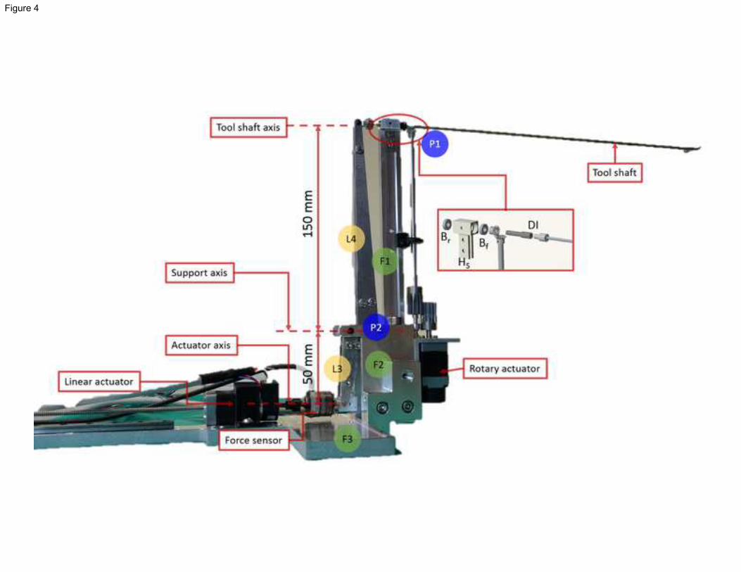
Figure 4

Figure 5

Figure 6

Figure 7a

Figure 7b

Figure 8

Figure 9

Figure 10a

Figure 10b

Figure 11a
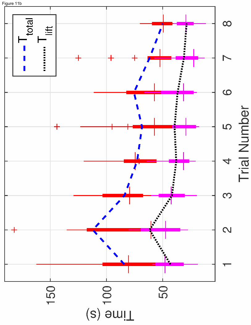
Figure 11b

Figure 12a

Figure 12b
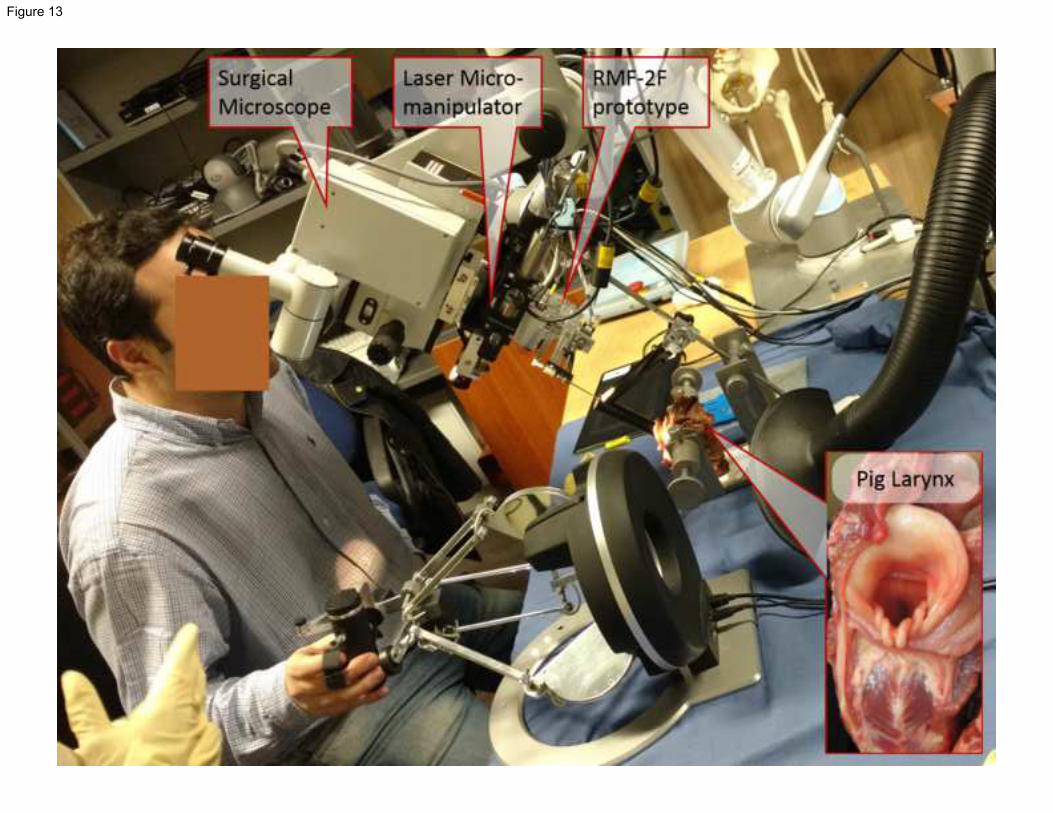
Figure 13

TABLE 1: Design specifications of the microsurgical forceps
Design Needs / Features Remarks
1.
Displacement from microscope
line-of-sight of 200mm.
To minimize vision occlusion and avoid tool interference with laser path,
sufficient distance between the laryngoscope entry point and the designed
tool base is necessary.
2.
Tool cross-section under the
microscope of <10mm.
To maintain minimum vision occlusion, when viewed through the
microscope.
3.
Introduce tissue surface perception
through haptic feedback.
To receive tissue gripping force feedback.
4. Introduce tool rotation DOF. Enhance tool capability for enhanced workspace and reachability.
Table 1

TABLE 2: D-H Parameters for the RMF-2F integrated device
Joint Type a (m) α (radians) d (m) q (radians)
1 R 0.00000 𝜋/2 𝑑1 = 0.089159 𝑞1
2 R -0.42500 0.0 0.0000 𝑞2
3 R -0.39225 0.0 0.0000 𝑞3
4 F 0.00000 𝜋/2 𝑑4 = 0.10915 0
5 F 0.00000 − 𝜋/2 𝑑5 = 0.09465 0
6 F 0.00000 0.0 𝑑6 = 0.0823 + 𝑙6 0
7 R 0.00000 𝜋/2 𝑑7 = 0.108 + 𝑙7 𝑞𝑟𝑜𝑡
R = Rotary; F = Fixed. 𝑙6 = 210mm, 𝑙7 = 200mm are dimensions of micro-forceps. 𝑞𝑟𝑜𝑡 = rotary DOF.
Table 2


![Research Article Radiofrequency Transoral Microsurgical ...a vallecular cyst [ ], and Kumar et al. in the removal of a laryngeal cyst [ ]. In adductor spasmodic dysphonic microlaryngealRF](https://img.dokumen.tips/doc/110x75/60c722fd93fe8857a20a37ec/research-article-radiofrequency-transoral-microsurgical-a-vallecular-cyst-.jpg)