Embed Size (px)
Citation preview

Review ArticleA Review on Computational Fluid Dynamics Applications in theDesign and Optimization of Crossflow Hydro Turbines
Hamisi Ally Mrope , Yusufu Abeid Chande Jande , and Thomas T. Kivevele
Nelson Mandela African Institution of Science and Technology (NM-AIST),�e School of Materials, Energy, Water, and Environmental Sciences, P. O. Box 447, Arusha, Tanzania
Correspondence should be addressed to Hamisi Ally Mrope; [email protected]
Received 10 February 2021; Revised 6 July 2021; Accepted 27 July 2021; Published 15 October 2021
Academic Editor: Jing Shi
Copyright © 2021 Hamisi Ally Mrope et al. )is is an open access article distributed under the Creative Commons AttributionLicense, which permits unrestricted use, distribution, and reproduction in any medium, provided the original work isproperly cited.
In recent years, advances in using computational fluid dynamics (CFD) software have greatly increased due to its great potential tosave time in the design process compared to experimental testing for data acquisition. Additionally, in real-life tests, a limitednumber of quantities are measured at a time, while in a CFD analysis all desired quantities can be measured at once, and with ahigh resolution in space and time. )is article reviews the advances made regarding CFD modeling and simulation for the designand optimization of crossflow hydro turbines (CFTs). )e performance of these turbines depends on various parameters like thenumber of blades, tip speed ratio, type of airfoil, blade pitch, chord length and twist, and its distribution along the blade span.Technical aspects of the model design, which include boundary conditions, solution of the governing equations of the water flowthrough CFTS, and the assumptions made during the simulations are thoroughly described. From the review, a clear idea on thesuitability of the accuracy CFD applications in the design and optimization of crossflow hydro turbines has been provided.)erefore, this gives an insight that CFD is a useful and effective tool suitable for the design and optimization of CFTs.
1. Introduction
Computational fluid dynamics is the discipline of predictingfluid flow, heat and mass transfer, chemical reactions, andrelated phenomena by resolving a set of governing mathe-matical equations numerically: conservation of mass, mo-mentum, energy, and species mass. It is an important tool usedin fluid mechanics to solve and analyze problems that involvefluid flow through numerical methods and algorithms. )eCFD has been used to predict the behavior of fluid flow byapproximations that solve partial differential equations (PDEs)governing flows. For its efficacy, the procedure for determiningthe degree to which CFDmodel is an accurate representation ofthe real world from the viewpoint of the projected use is es-sential. CFD solutions must indicate the error bands and un-certainties incurred in the results to have confidence in thepredicted results [1].
Practical hydraulic turbine method has become acompelling technique to capture minor details of the flow
which are unbearable in the physical model testing andovercome the limitations of the physical laboratory setup [2].Complementary to experimental investigation, the numer-ical simulation of flows is an auspicious way to investigateflows at real operating conditions [3].
Although the key geometric features and their effectson turbine efficiency have been experimentally studied,this knowledge does not readily help to design high-ef-ficiency turbines, partly because of the knowledge aboutthe details of the runner flow. As it is difficult and ex-pensive to measure and visualize the flow fields in therunner, the alternative is computational simulation [4].)ere are various CFD simulation codes available in theindustry and designed for the application of computer-aided engineering. However, in crossflow turbine mod-eling, there is a necessity to select an accurate CFD code,which will save time and cost of simulation. CFD solversare based on the finite volume method, whereby the fluidregion is decomposed.
HindawiJournal of Renewable EnergyVolume 2021, Article ID 5570848, 13 pageshttps://doi.org/10.1155/2021/5570848

Into Finite Set of Control Volumes. General conservationequations of mass, momentum, energy, and species aresolved on this set of control volumes.
Crossflow turbines were conceived by Michell [5] whoreferred to them as Michell-Banki turbines or impulseturbines in which water strikes the turbine transverselyacross its blades. )e maximum efficiency of crossflowturbines tends to be 70–86%, which is weaker than that ofmore frequently used advanced turbines such as Pelton,Francis, and Kaplan, which have typical maximum effi-ciencies above 90% [6, 7].
)e crossflow turbine operates with ambient air pressureon the free surface [8]. However, since the crossflow hydroturbines had low price and were mostly suitable formicrohydropower units less than 2MW and heads less than200m, they are mostly appropriate for the production ofelectricity particularly in rural communities of developingcountries. Despite being enriched with perennial rivers,most of these communities lack electricity.
In demand to improve the efficiency of CFT, a com-mercial CFD simulation code has been used to study theturbine operation and determine the parameters and phe-nomena that affect its performance [2]. CFT has beensuccessfully used [1, 4, 9–11] because, among others, itshorizontal efficiency curves yield better annual performancein small river flows than other turbine systems, which arelesser in some months. Moreover, CFTs have a relativelysmall efficiency and can maintain efficiency under varyingload and water flow conditions, the primary inspiration toimprove its existing design.
Both numeric and experimental tests have been used forthe design and optimization of CFTs. However, the trends ofsimulated and experimental efficiency curves are similareven if the experimental efficiency values are always a bithigher than the simulated ones [4, 9, 12–22]. Moreover,many of the authors argue that experimental tests provide agood validation of the results obtained by means of CFDanalysis.
In the process of designing and optimizing CFTs, similarparameters are used in both experimental and numericalmethods. Parameters that are used to influence the im-provement of the performance of crossflow turbines areshown in Table 1 below [23].
Vital geometrical parameters of crossflow turbine asdescribed in its cross section are as shown in Figure 1.
2. CFD Modeling Overview
CFD analysis can be categorized into four main steps(Figure 2): problem identification, preprocessing, solver/solution, and postprocessing. Figure 1 shows the main stepsof performing a CFD analysis.
2.1. CFD. )is is the first step in the numerical simulationwhereby at least four activities are done: the formation ofa robust model to characterize the domain mesh gen-eration, set up fundamental physics, and define solversettings.
2.2. Solver. )e second step in the numerical simulationanalysis is the solver. )e CFD solver is used to set thenumerical schemes and convergence control and performcomputation. To produce a good result, the fundamentalunderstanding of preprocessing is essential.
2.3. Postprocessing. )e last stage in conducting CFD analysisis the postprocessing. In this stage, the results are examined.)eCFD postprocessing can perform flow field visualization andquantitative data analysis. CFD simulation codes can presentand plot flow variables on a point, line, and any plane of interest.Statistical reporting tools can be used to compute quantitativeresults such as forces and moments, average heat transfer co-efficients, and flux balance.
3. Validation of CFD Codes with Experiments
)ere was a need to review validations on CFD codes withexperiments in order to demonstrate their accuracy and
Table 1: Important parameters in crossflow turbine.
S/No Design parameter Unit01 Outer diameter mm02 Inner diameter mm03 )e angle of attack Degree04 Outer blade angle Degree05 Inner blade angle Degree06 Blade radius mm07 Blade thickness mm08 Number of blades —09 Impeller and nozzle width mm10 Nozzle thickness or throat mm11 Nozzle entry arc angle Degree
Nozzle inlet
Nozzle high velocity flow
Nozzle rear wall
First stage
Second stage
Exit flow
Runner
Inlet flow
Free-stream,air-space region
ω
δ
β1h0
R2
R1
R
θsW2 u2
u2u3
u
WW4
u4u1
u1u1
Figure 1: Critical geometrical parameters of crossflow turbine.Respondent [4] (copyright (2018), with permission under CreativeCommons Attribution 4.0 International License).
Solver Post-Processing
Pre-Processing
ProblemIdentification
Figure 2: CFD modeling overview.
2 Journal of Renewable Energy

suitability for design and optimization activities. Moreover,this provides a clear insight on the prospects including consand pros of CFDs.
Modeling and uncertainties are due to assumptions andapproximations in the mathematical representations of thephysical problem and incorporation of previous data intothe model (such as fluid properties), and the physicalproblem in modeling includes geometry, mathematicalequation, coordinate transformation, boundary conditions,and turbulence models. Numerical errors and uncertaintiesare due to the numerical solution of the mathematicalequations (such as discretization, artificial dissipation, in-complete iterative and grid convergence, lack of conserva-tion of mass, momentum and energy, internal and externalboundary noncontinuity, and computer round-off [22]).
)e procedure of determining the degree to which amodel is an accurate representation of the real world fromthe viewpoint of the projected uses of the model is essential.CFD solutions must indicate the error bands and uncer-tainties incurred in the results in order to have confidence inthe predicted results [1]. Experimental hydraulic turbinemethod has become a compelling technique to captureminor details of the flow which are unbearable in thephysical model testing and overcome the limitations of thephysical laboratory setup [2]. Complementary to experi-mental investigation, the numerical simulation of flows,commonly referred to as CFD, is an auspicious way to in-vestigate flows at real operating conditions [16].
[24] studied the effect of the nozzle in the performance ofcrossflow hydro turbines. It concluded that nozzle rear-wallshape for both circular and logarithmic spiral rear-wall gavethe same maximum efficiency of the crossflow hydroturbine.
[21, 22] focused on developing a suitable numericalmodel such that the results have a close agreement withexperiments. In their studies, the authors made a compar-ison of three numerical models (k- ε, RNG, and SST) inwhich one of the studies showed that SST turbulence modelhas an efficiency of 67.3%–67.7% for CFT and 71% for theexperiment. From these results, the efficiencies of the CFDand experiment had a close match with the experimentalresults, even if the experimental efficiency values were higherthan the simulated ones.
Commercial CFD ANSYS codes have been used tocompare RANS/URANS transition and scale resolvingsimulation (SRS) turbulence methods. Studies showedthat CFD simulation applications are computationallypracticable and suitable for most of the turbo machinerydesign analysis [25–27]. Moreover, flow field simulationsfor predicting the action of turbine performance on free-surface flow situations have appeared due to the complexnature of this physic spectacle [10]. )is authenticates itsrole in improving efficacy and reducing the effort and costrequired for experimentation thus facilitating betterdesigns of CFTs. )is suggests that the advancement inCFD simulation codes has allowed researchers and en-gineers to confront the complex nature of the physicspectacle by modeling to obtain three-dimensional flowfield simulations in turbines.
Results in Figure 3 and Table 2 show a comparison ofCFD and experimental results for the power output of0.268–12.54KW. For the power output of 7 kW (Figure 4),there is a satisfactory agreement between CFD and exper-imental results with a relative error of less than 6%. Similarly,CFD and experimental results for 0.53 kW turbine differedby less than 3.8%. )e results elucidate that CDF has fa-cilitated the conversion of the head into kinetic energy andmatching of nozzle flow with runner design. )is points outthat CDF is crucial in turbine design.
[32] conducted a study on the performance improve-ment of CFT by air layer effect. CFD analysis on the per-formance and internal flow of the turbine was conducted inthe unsteady state using a two-phase flow model to embodythe air layer effect on the turbine performance effectively.From the results, the air layer effect on the performance ofthe turbine is considerable. )e air layer located in theturbine runner passage plays a role of preventing shock lossat the runner axis and suppressing a recirculation flow in therunner. Moreover, the ratio of air from the suction pipe towater from the turbine inlet is also a significant factor in theturbine performance. )e difference of efficiency ratio be-tween experiment and CFD was 1.4%.)is disparity was dueto the difference in mechanical loss because the amount ofmechanical loss predicted by CFD analysis is usually smallerthan that obtained by experiment.
Figure 5 shows the use of CFD tools in the design of aninternal deflector for CFT efficiency improvement [33].Commercial CFD code ANSYS CFX v.13 was used to carryout all simulations. A transient regime, two-dimensional,two-phase (air-water) homogeneous model with a Eulerian-Eulerian approach was selected, and the SST turbulencemodel was preferred. )e results obtained concluded thatthe performance of a CFD model was in line with the ex-perimental data. Maximum efficiency deviation from theexperiment was around 5% at the three evaluated specificspeeds.
From the investigation results in Figure 5, it was alsofound that the overall use of the internal deflector increasesCFT performance and output power. Prasad et al. [37]studied the flow control in Banki turbines by using ANSYSFluent code with k-ωSST turbulence model for numericalanalysis. )e study showed that the experimental and nu-merical simulation results were reasonably good. Based onthe CFD fluent code analysis, the velocity fields obtained bynumerical simulations, which are responsible for the de-crease in turbine efficiency, were identified.
Numerical investigation of a turbine in a transient statereaction determination was conducted by [38]. )e inves-tigation was conducted purposely to understand the flowinside CFTs using CFD tools.
Furthermore, steady and transient state simulations wereperformed for a CFT at a specific speed Ns� 45. )e resultsobtained from SST and k- ε turbulence models were com-pared in terms of simulation requirements. In addition, theproposed runner-nozzle interface by considering a real CFTexistent gap between these two components was comparedwith the available experimental data. )e study revealed thatthe maximum numerically calculated efficiency deviated
Journal of Renewable Energy 3

from the reported experimental global efficiency by 15%. Inthis investigation, a two-dimensional approach was selected.)e obtained results, which deviated from the experimentalvalues, agree with those reported for three-dimensionalcomputation for the same CFT.
Hence, it is recommended that the two-dimensionalapproach could be used whenever a three-dimensionalcomputation is not feasible due to hardware and time re-quirements. Moreover, the analysis suggests that steady-stateconditions are not recommended for CFT studies as theresults in terms of flow behavior are not as accurate andrepresentative of real CFT like those obtained from transientstate computations.
Crossflow turbine design for variable operating condi-tions studies was conducted by CFD code. A 2D simulationof the CFX-ANSYS code was used to get the maximumefficiency very close to the design flow. In the study, the flowrate can be maintained when Q is reduced to 20% of itsmaximum by using the flow control mechanism [6].
A study of flow and performance features of a directdrive crossflow turbine for wave power generation usingcommercial CFD code ANSYS-CFX for simulation showedgood agreement with the experimental data at the waveperiod of 2 s and a 3% difference in the results was noted[38]. Moreover, the power of the turbine was high at T� 3 sfor all turbine speeds. From the study, it is noted that theefficiency increases with an increased turbine speed, andthen it reaches a maximum and then decreases (Figure 4).
Experimental and numerical investigations (using CFD)of a crossflow turbine [17] concluded that the experimentalefficiencies showed a good agreement with their numericalapproximation. Furthermore, the impeller shaft provides asignificant reduction in turbine efficiency, for a velocity ratioclose to the optimal value (Vt/U� 1.8–2.0), and an impellerwith a shaft has 5% lower efficiency than that without a shaft.)e efficiency curves tend to assume the same value for thetwo cases by reducing the velocity ratio. )e efficiency isabout 75% for a velocity ratio Vt/U close to 1.2. In addition,
Table 2: Performance comparison.
S/No Author Targeted power Modal Head Flow rate Flow control mechanism Efficiency01 [29] 7.20 kW SST 10.0m 0.10m3/s Guide vane 76.6%02 [30] — k-ε — — Guide vane Less than 80%03 [1] 7.00 kW (SST) k 10.0m 0.11 m3/s —04 [15] — k-ωT 1.2m 0.23 m3/s — 58%05 [31] 7.00 kW (SST) k 10 .0m 0.11 m3/s Control device 87%06 [10] — k-ε — — — 71%07 [32] 6.50 kW SST 4.3m 0.25 m3/s Guide vane 76.04%08 [9] — k-ε — — — 82%09 [33] 0.26 kW SST — — Internal deflector 81%10 [34] 0.51 kW SST 2.9m — — 65.7%11 [35] k-ωT 1.2m 0.23 m3/s — 58%12 [12] RNG 15.0m 0.95 m3/s — 80%13 [36] — SST 20.0m 0.53 m3/s Guide vane 80%14 [13] 12.54 kW k-ε 10.0m 0.15 m3/s Guide vane 86%
0.00
1.00
2.00
3.00
4.00
5.00
6.00
7.00
8.00
6.46 6.90 7.22 7.17 6.70
Pow
er O
utpu
t (Kw
)
Runner Speed (RPM)
Steady SST k-wSteady k-wURANS SST k-w
ExperimentSteady SST k-w 2Experiment 2
Figure 3: Comparison of CFD and experimental outcomes [4]. Experimental data were taken from [28] (copyright (1982), with permissionunder Creative Commons Attribution 4.0 International License).
4 Journal of Renewable Energy

from the study it was observed that a maximum efficiencyvery close to the design flow rate was attained when Q wasreduced to 20% of its maximum. 2D numerical simulationswere carried out employing ANSYS CFX code. )e k-εturbulence model was selected using ANSYS CFX code.
[39] conducted a numerical investigation of the flowprofile and performance of a low-cost crossflow turbine.ANSYS CFX with k-ε turbulence model was employed in thesimulation process. It was observed that the numerical studyobtained the flow profiles that had a favorable correlationwith the actual flow pictures. Additionally, the study con-cluded that the numerically determined performance resultscompare favorably with the experimental results.
Generally, these reviews have not only demonstrated thevalidity of CFD models but also pointed out the prospects ofusing CFD for designing and optimizing a CFT. )erefore,
the findings suggest that it is plausible that numericalmodeling with CFD is a powerful alternative to experimentaldesigns because it can avoid some limitations and providedetailed information on the relevant flow variables in thefield data, under well controlled conditions and withoutsimilarity constraints. However, the accuracy of CFD is animportant matter of concern. )erefore, adequate care isrequired in the implementation of the model, in grid gen-eration, and in selecting proper solution strategies.
CFD simulations were used to analyze the internal flowin a hydraulic crossflow turbine using a nozzle, runner, shaft,and casing. Analysis of the velocity and pressure fields of thecrossflow within the runner and characterization of itsperformance for different runner speeds was conducted. Inthe study, ANSYS CFX code with water-air free surface andk-ε turbulence model was used. )e simulation results were
7.00e+006.72e+006.51e+006.30e+006.09e+005.88e+005.67e+005.46e+005.25e+005.04e+004.83e+004.62e+004.41e+004.20e+003.99e+003.78e+003.57e+003.36e+003.15e+002.94e+002.73e+002.31e+002.10e+001.89e+001.68e+001.47e+001.26e+001.05e-008.40e-016.30e-014.20e-012.10e-010.00e+00
n = 50 RPM
n = 25 RPM
1
4
3
5
2
6
Figure 4: Comparison between numerical hydraulic efficiency and experimental global efficiency with runner speed [10] (copyright (2011),with permission under Creative Commons Attribution 4.0 International License).
Journal of Renewable Energy 5

related to the experimental data and showed that they wereconsistent with the global performance parameters. How-ever, a typical maximum relative error of 10% between thecomputational fluid dynamics (CFD) and experimentalresults has been reported [10]. )ese results suggest that,despite the observed error of 10%, there are high chancesthat due to its efficacy in terms of time and resources it mightbe more feasible.
An experiment and numerical investigation of a CFT,operating far away from design point, was studied by [15].)e experimental results suggested that even for operating atheads and discharges that go below 5% and 30% the turbinecould still reach a peak efficiency of more than 55%, althoughat the expense of a significant reduction in speed. To developan understanding of the flow through the turbine, arith-metical simulations were carried out by commercial codeANSYS Fluent. )e two-phase flow of water and air wasconsidered unsteady and turbulent. )e study showed that,above 175 rpm, there is a good agreement between themoment values obtained experimentally and numerically.)e study concluded that experimental results and those ofnumerical simulations are in good agreement, but it was notstated to what extent.
4. Advances in the Optimization of CFTs
Aeroplane industry was the first to use CFD applicationswhich gave results relevant for conceptual studies of newdesigns, full product development, troubleshooting, andredesign by, among others, reducing the total effort and costrequired for experimentation [40]. Since then, as a result ofthe continuous advancement of CFD tools and exponentially
increased computation capabilities along with better un-derstandings of the underlying physics, CFD simulationshave increasingly been applied widely in diverse areas in-cluding process safety and loss prevention in processingindustries, and improved efficiency of turbines. CFD wereextensively used [41] for power plants simulations such asthermal patterns of boiler furnaces and turbine bladingperformance as well as heat exchangers designs. Moreover, itcan be inferred from the research papers that CFD, amongothers, reduces the total effort and cost required for ex-perimentation and thus is of great benefit in improvingefficiency, rapid development, and enabling broadapplications.
Being a computer-based mathematical modeling tool,the application of CFD incorporates the solution of thefundamental equations of fluid flow, the Reynolds-AveragedNavier-Stokes equations, using computerized software andturbulence models to work out the averaged turbulencestresses. Commonly used CFD software for design andoptimization of CFTs includes ANSYS CFX, ANSYS Fluent,CFD2000, STAR CCM+, FLUENT, STAR-CD, andPHOENICS. Moreover, in recent studies [8, 9, 18–22],ANSYS CFX software has been used to evaluate the smallefficiency of CFTs and has shown to be a primary inspirationto improve its existing design since these turbines operatewith ambient air pressure on the free surface [8]. Nowadays,CFD simulation codes are regarded as an industry standardfor this process [42].
Application of CFD simulations in the optimization ofCFTs provides detailed information on manipulation of thegeometry characteristics, and other parameters in optimi-zation of CFTs. It also offers a relatively economical and safe
0.00
10.00
20.00
30.00
40.00
50.00
60.00
70.00
80.00
400 500 600 700 800 900 1000 1100 1200 1300
Effici
ency
(%)
Runner Speed (RPM)
Hydraulic EfficiencyGlobal Efficiency
Figure 5: Air-water volume fraction and velocity fields inside the Banki turbine at two speeds: (a) n� 50 rpm and (b) n� 125 rpm. )ebackground color indicates the air-water volume fraction (blue for water, red for air). )e legend shows velocity values [15] (copyright(2011), with permission under Creative Commons Attribution 4.0 International License).
6 Journal of Renewable Energy

approach that enables design modification of CFTs and is ofgreat benefit to improving efficiency of CFTs. Additionally,CFD simulations help to evaluate and optimize the effec-tiveness of various mitigation methods, especially thosewhich are too costly or dangerous for which to conductexperiments. )is review has identified geometry optimi-zation and flow features as two important categorical at-tributes in the design and optimization of CFTs.
4.1. Analysis of Nozzle Parameters. Various studies[1, 9, 10, 12, 13, 15, 29, 32, 35, 36, 38, 43] have used CFD foroptimizing these parameters in order to influence the im-provement of the performance of crossflow turbines.According to the studies, ANSYS CFX software has beenhighly used to perform simulations and analysis of turbinescompared to other CFD software. )is is probably due to itshigh-level potential for general purpose in CFD analysis.Similarly, a large number of turbulence models, which areavailable in the ANSYS CFX software and have been usedwith specific applications to the broader class of flows for areasonable degree of confidence, include standard k-ε, RNGk-ε, standard k-ω, SMC- ω, and SST k- ω. In CFTs, CFD isfound to have been used for optimizing the shapes of thenozzles in many studies [18–20]. Global performance pa-rameters were presented for different operating conditions.[44], and [45] have investigated through 2D numericalcalculations the unsteady water flow inside the runner,paying attention to the flow along the runner entrance andunsteady forces on the blades. On the other hand, Choi et al.performed an entire 2D-CFD steady-state crossflow turbinesimulation, considering water and water-air flow conditions.With this approach, the authors studied the influence ofnozzle shape, runner blade angle, and runner blade numberon the turbine performance. Moreover, the important role ofthe air layer on the numerical calculation was verified. It wasalso studied [18] that the presence of an air layer in therunner passage improves the turbine’s performance bypreventing the collision loss between the flow and shaft, andeliminating the recirculation flow in the passage. One of thestudies [9] has also implemented a Multiobjective GeneticAlgorithm and a Metamodel-Assisted Optimization to op-timize the shape of the valve in crossflow turbines and foundimprovement in the output power by 4.73% and 5.33%,respectively.
)e effects of nozzle inclination on the performance ofcrossflow hydro turbine were investigated by [14, 24, 46–48].)e inclination angle of 16° was found to provide maximumefficiency between 80 and 82% ([24, 46]). Nozzle inclinationof 24° gave a maximum efficiency of 89% by [47]. [14] foundefficiency of 88% at an inclination of 22°. Also, [48] reportedan efficiency to be maximum at an inclination of 22° and got90%.
Using a base model, numerical analysis and performanceimprovement of a crossflow hydro turbine enabled designmodification by optimizing the nozzle shape and guide vaneangle, and changing the number of blades. A CFD codeANSYS CFX 13.0, two-phase air and water at 25C° withsteady state and SST turbulence model was selected. From
the study, the best efficiency found from the base nozzle was63.67%, which was geometrically altered and improved theturbine performance and efficiency up to 76.60 [29]. )iselucidates that the efficiency increased by 12.93%. Velocityvectors of the base model and the modified model are shownin Figure 6.
Similarly, a numerical study on the effect of guide nozzleshape on the performance improvement of low headcrossflow turbine showed an increase in efficiency by 12.5%to 76.04% [13]. From this study, it is depicted that theappropriate guide nozzle radius and nozzle angles play anessential role on the relative angle that should be close to theinlet angle of the blade. However, the influence of the guidenozzle on the perfect angle at the outlet of stage 2 (Figure 1)decreased. Moreover, it is observed that the guide nozzleplays a role of suppressing the negative torque by reducingthe pressure difference on the blades.
Design modification was done by optimizing the nozzleshape and guide vane angle and changing the number ofblades using CFD simulation code ANSYS CFX 13.0,whereby two-phase air and water at 25C° with steady stateand SST turbulence model was selected. From the study, thebest efficiency found from the base nozzle was 63.67%, whichwas geometrically altered and improved the turbine per-formance and efficiency up to 76.60 as shown in the velocityvectors of the base model and the modified model in Fig-ure 6. )ese findings elucidate that it is plausible that CFDfacilitates efficient design for improved performance andgains of CFT.
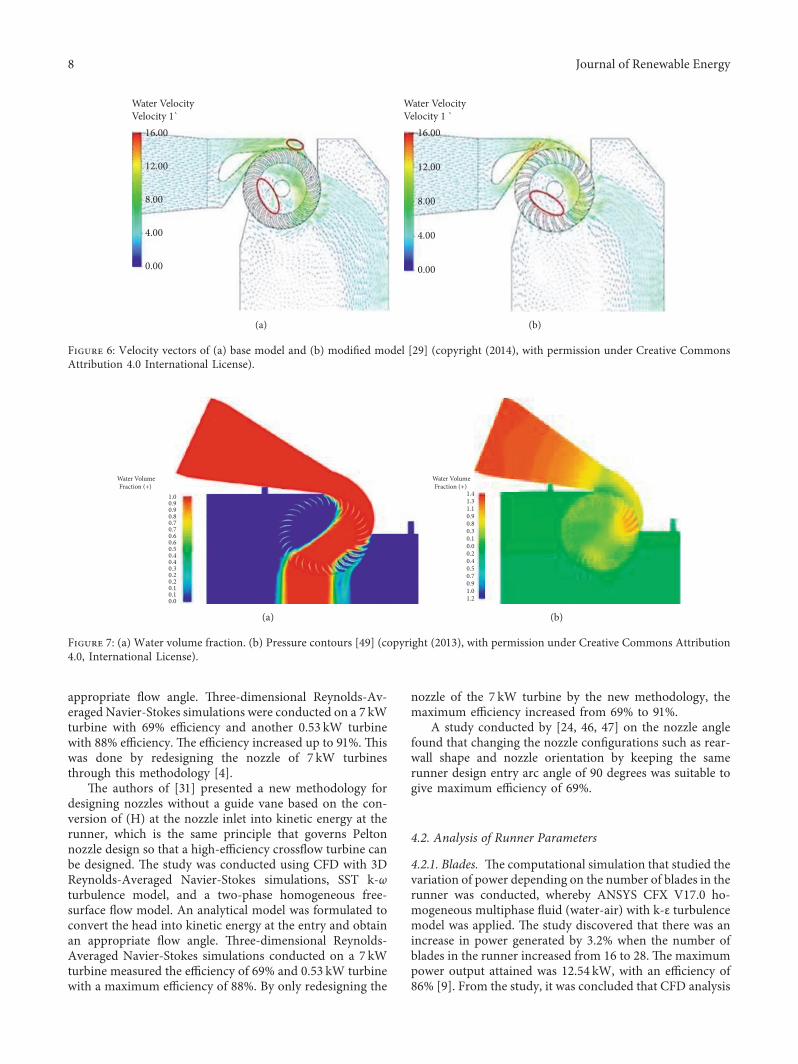
Pressure and velocity profiles along with nozzle outlet,energy transfer stage location, and CFTreaction values wereaddressed (Figure 7). )e attained results were compared interms of the runner-nozzle interface (gap vs no gap), tur-bulence model (SST vs k-ε), and calculation regime (steadyvs transient simulation). )e study revealed that the cal-culation state (steady vs transient simulation) was found tohave a significant influence over the results. Transient statecalculations presented a better complex flow inside the CFT.)e 3D simulations carried out for the designed optimalconfiguration suggest an optimal value of the ratio betweenthe width of the impeller and the nozzle equal to one; thisvalidates the adopted 2D approach but disagrees withprevious literature results [14]. Figures 7(a) and 7(b) showwater volume fraction and pressure contours. According to[49], the average efficiency of the turbine was greater than80% for a value of Vt/U varying between 1.2 and 3.0(corresponding to a water discharge varying between 35 l/sand 90 l/s). )e distributions of the water volume fraction,the velocity field, and the pressure in the simulated sub-domains for the optimum configuration are shown.
A new methodology for designing nozzles without aguide vane based on the conversion of H at the nozzle inletinto kinetic energy at the runner was presented [41]. )esame principle governs Pelton nozzle design for high-effi-ciency CFTs. 3D Reynolds-Averaged Navier-Stokes simu-lations uses SST k-ω turbulence model and a 2-phasehomogeneous free-surface flow model. Using numericalsimulations, an analytical model was formulated to convertthe head into kinetic energy at the entry to obtain an
Journal of Renewable Energy 7
appropriate flow angle. )ree-dimensional Reynolds-Av-eraged Navier-Stokes simulations were conducted on a 7 kWturbine with 69% efficiency and another 0.53 kW turbinewith 88% efficiency. )e efficiency increased up to 91%. )iswas done by redesigning the nozzle of 7 kW turbinesthrough this methodology [4].
)e authors of [31] presented a new methodology fordesigning nozzles without a guide vane based on the con-version of (H) at the nozzle inlet into kinetic energy at therunner, which is the same principle that governs Peltonnozzle design so that a high-efficiency crossflow turbine canbe designed. )e study was conducted using CFD with 3DReynolds-Averaged Navier-Stokes simulations, SST k-ωturbulence model, and a two-phase homogeneous free-surface flow model. An analytical model was formulated toconvert the head into kinetic energy at the entry and obtainan appropriate flow angle. )ree-dimensional Reynolds-Averaged Navier-Stokes simulations conducted on a 7 kWturbine measured the efficiency of 69% and 0.53 kW turbinewith a maximum efficiency of 88%. By only redesigning the
nozzle of the 7 kW turbine by the new methodology, themaximum efficiency increased from 69% to 91%.
A study conducted by [24, 46, 47] on the nozzle anglefound that changing the nozzle configurations such as rear-wall shape and nozzle orientation by keeping the samerunner design entry arc angle of 90 degrees was suitable togive maximum efficiency of 69%.
4.2. Analysis of Runner Parameters
4.2.1. Blades. )e computational simulation that studied thevariation of power depending on the number of blades in therunner was conducted, whereby ANSYS CFX V17.0 ho-mogeneous multiphase fluid (water-air) with k-ε turbulencemodel was applied. )e study discovered that there was anincrease in power generated by 3.2% when the number ofblades in the runner increased from 16 to 28. )e maximumpower output attained was 12.54 kW, with an efficiency of86% [9]. From the study, it was concluded that CFD analysis
Water VelocityVelocity 1`
16.00
12.00
8.00
4.00
0.00
(a)
Water VelocityVelocity 1 `
16.00
12.00
4.00
8.00
0.00
(b)
Figure 6: Velocity vectors of (a) base model and (b) modified model [29] (copyright (2014), with permission under Creative CommonsAttribution 4.0 International License).
Water VolumeFraction (+)
1.00.90.90.80.70.70.60.60.50.40.40.30.20.20.10.10.0
(a)
Water VolumeFraction (+)
1.41.31.10.90.80.30.10.00.20.40.50.70.91.01.2
(b)
Figure 7: (a) Water volume fraction. (b) Pressure contours [49] (copyright (2013), with permission under Creative Commons Attribution4.0, International License).
8 Journal of Renewable Energy

applied in the investigation showed results with high ac-curacy compared to real experiments, thus indicating theresults of fluid computational analysis to be reliable.
)e impact of the number of blades on the powergenerated by a Michell-Banki turbine was studied by [13].Computational fluid dynamics ANSYS CFX v17.0 code wasemployed as a solver. Homogeneous turbulence model wasused for the multiphase fluid (water-air) with k-ε turbulencemodel for both phases implemented. )e authors found thatthere was an increment of 3.2% in the power generated bythe turbine when the number of blades in the runnerchanged from 16 to 28. )e maximum output power of12.54 kW with an efficiency of 86% was obtained. From thestudy, it was concluded that the CFD analysis applied in theinvestigation showed results with high accuracy comparedwith real experiments, which allows the results of the fluidscomputational analysis to be reliable.
Crossflow turbine is a possible choice for the exploitationof small hydropower sources because of their simplicity andtheir excellent efficiency, but a complete step-by-step pro-cedure for their design was missing to the authors knowl-edge [49]. A CFD ANSYS CFX code was used to analyzesome design parameters on the influence of inefficiency. Aturbine with 35 blades and an attack angle equal to 22°exhibited at the design point a high efficiency equal to 86%.2D CFD analyses showed that the linear nozzle ensures analmost constant value of the angle of attack and confirms thesimplifying hypothesis of negligible energy dissipation in-side the impeller, which is a cornerstone of the theoreticalapproach [49]. From the study, the number of blades anddiameter ratio had little influence on the peak efficiency,while the presence of the shaft did not affect the charac-teristics curve but led to a considerable reduction inefficiency.
Investigation of the effects of several blades on theperformance of a crossflow turbine using Star CCM+ wasdone by [2]. )e study used CFD Star CCM+ simulationcode combined with CATIA V5 computer-aided designsoftware to improve the operation of the turbine, accordingto the analysis result to establish the optimal number of therunner blades for the chosen turbine. )e internal flowsimulation is used to characterize the turbine performancefor a different number of blades. Six different turbinerunners of 15, 20, 25, 30, 35, and 40 blades were investigated,and the study showed that 30-blade runner was the mosteffective. )e prediction results revealed key and excitingdetails of the structure of the flow in the runner of thecrossflow turbine by using the different number of blades.Such details revelations are not possible with conventionalflow visualization or other techniques.
4.2.2. Rotor. Numerical simulations have been carried outimposing a constant rotor rotational speed, n� 245 rpm, inall the simulations [50]. Hence, in order to guarantee thedesired Utip/V∗ ratio, the head difference between the up-and downstream ponds, Ht, has been opportunely assigned.Four simulations have been performed considering thefollowing flow coefficients:U∗ � 0.165,U∗ � 0.200,U∗ � 0.25,
and U∗ � 0.293, or in terms of Utip/V∗ ratios: 5.6, 4.6, 3.7,and 3.2. )e solutions have been initialized by imposinguniform flow conditions computed from the inlet boundary.)ree blades were observed to behave the same way and therotor had not only a geometric but also a fluid dynamicperiodicity reported in terms of pressure drop coefficient, Δp∗, nondimensional torque∗, and efficiency, η vs. flow co-efficient, U∗.
4.2.3. Flow Features. CFD techniques have proven to beversatile tools in evaluating the hydraulic performance ofhydro turbines [50]. In demand to improve their efficiency,commercial CFD simulation code has continued to be usedto study and determine parameters and phenomena thataffect their performance [50].
A study was conducted on flow features in crossflowturbine T15 300 by CFD deployed Fluent 14.5 with thestandard k-ε turbulence model as observed by Legonda [30]and a comparison of the values of efficiency extracted froman experimental performance test reported by Entec [51] onthe guide vane angle against the total pressure shown inFigure 8. According to the comparison, there exists sensi-tivity to the guide vane angle and shaft diameter on theoverall performance of the turbine.
)e study highlights a strong correlation between effi-ciency and pressure in the crossflow turbine. From the study,it is suggested that the model prediction is in good agree-ment with the experimental data. However, the result doesnot mention to what percentage.
)e results in Table 2 show the use of CFD in the designof CFT targeting variable power and using diverse head, flowrates, and flow control mechanisms. In the results, the ef-ficiencies obtained are a minimum of 58% and a maximumof 86%. )e mean efficiency is 75.5% and considering thefrequency of the efficiencies at the range of 58.0–68.0% threeresearchers obtained this efficiency [15, 34, 35], three re-searchers obtained 68–78.0% [10], and [29, 32] and sevenresearchers obtained 78 – ≥88% [1, 12, 13, 30, 31, 36].Moreover, the results show that the highest efficiencies of≥82 are during use of CFD software and ANSYS CFX codewith turbulence model k-ε, SST. )ese results explain thatthe application of CFD software and associated turbulencemodels is effective in designing improved CFTs for devel-opment of renewable energy technologies. )is is supportedby [42], that CFD simulation codes are an industry standardfor design of turbines.
Numerical computation of flow through SSH-300/150and TP-300/300 turbines was done to determine the fields ofpressure and velocity, and the final specification of theirefficiency in different points of operation. )e analysis wasperformed using the CFD fluent 5.0 code based on the finitevolume method with RHG k-ε model. )e analysis of theflow A through SSH-300/150 model turbine showed that therunner operates in a pumping regime on the part of itsperimeter [12]. )is result is confirmed by an experimentaltest which was conducted in a laboratory test rig. Fur-thermore, the computation result showed the deadly flowfield in the internal part of the runner. To increase the
Journal of Renewable Energy 9

significance of the numerical results, the computationsconducted on efficiency showed that the experimental ef-ficiency was more than 80% while that of CFD was less than80%.)e study concluded that the newly designed TPP-300/300 crossflow turbine with a draft tube fulfills an essentialfunction of utilizing the difference in specific energy betweenthe runner bottom edge and the tail water surface.)erefore,the numerical computations performed on the new designshow that the properly designed draft tube reduces someundesirable phenomena like backflows and separation.
Figure 9 shows the results of a study on cavitationinception in CFT using 3D Reynolds-Averaged Navier-Stokes (RANS) computations with a homogeneous free-surface two-phase flow model [31]. Pressure distributionon the blades was examined for different rates, heads, andimpeller speed. )e aim was to assess cavitation incep-tion. In this study, cavitation occurred in the second stageof the turbine and was observed on the suction side nearthe inner edge of the blades [1]. )e study suggests thatcavitation may be an essential consideration for CFTs butonly if they are poorly designed to operate past themaximum efficiency point in terms of Q.
Furthermore, the study suggests that further experi-mental and numerical investigations are needed to test thegenerality of the specific conclusion reached from simula-tions done on the low-efficiency turbine. Figure 10 shows thevelocity contour in the crossflow hydro turbine.
[34] considered performance improvement ofcrossflow hydro turbine by air layer effect. CFD analysison the performance and internal flow of the turbine wasconducted with the unsteady state using a two-phase flowmodel in order to embody the air layer effect on theturbine performance effectively. )e result showed that
the air layer effect on the performance of the turbine isconsiderable. )e air layer located in the turbine runnerpassage plays a role of preventing a shock loss at therunner axis and suppressing a recirculation flow in therunner.
Moreover, the ratio between air from suction pipe andwater from the turbine inlet is also a significant factor in theturbine performance. Commercial CFD code of ANSYS-CFX was adopted, and the study showed that difference ofefficiency ratio between experiment and CFD was 1.4%.)isdifference between results by experiment and CFD analysiswas due to the difference in mechanical loss because theamount of mechanical loss predicted by CFD analysis isusually smaller than that obtained by experiment.
CFD tools were used in designing internal deflectorfor CFT efficiency improvement by [33]. CommercialCFD code ANSYS CFX v.13 was used to carry out allsimulations. A transient regime, two-dimensional, two-phase (air-water) homogeneous model with a Eulerian-Eulerian approach was selected, and the SST turbulencemodel was preferred. )e results obtained concluded thatperformance of a CFD model agreed with experimentaldata. Maximum efficiency deviation from the experimentwas around 5% at three evaluated specific speeds. )einvestigation also reveals that the overall use of internaldeflector increases CFT performance and output power.[35] studied the flow control in Banki turbines by usingANSYS Fluent code with k-ω SST turbulence model fornumerical analysis. )e study showed that experimentaland numerical simulation results were reasonably good.Based on the CFD fluent code analysis, the velocity fieldsobtained by numerical simulations which are responsiblefor the decrease in turbine efficiency were identified.
220
1900
2460
4385
0
10
20
30
40
50
60
70
80
0
500
1000
1500
2000
2500
3000
3500
4000
4500
5000
20 30 35 41
Tota
l Pre
ssur
e
Guide Vane Angle
Total PressureEfficiency
Figure 8: Comparison betweenmodel and experimental data [30] (copyright (2016), with permission under Creative Commons Attribution4.0 International License).
10 Journal of Renewable Energy

5. Conclusion
A review of the computational fluid dynamics applicationsin the design and optimization of crossflow hydro turbineshas demonstrated possible success in nonconventional so-lutions. CFD tools have shown to reduce cost and providequick solutions to the design of, among others, nozzle andrunner parameters of CFTs. In particular, the turbulencemodel SST k-ω and standard k-ε have widely been usedbecause of low cost and short run. Other models such asDNS and LES are not useful due to the high cost and ex-tended run time. Moreover, the results from CFD are ingood agreement with the experimental studies ranging from
2% to 10% but in some studies vary up to 15%. For a case ofsignificant deviation, which is very rare, it has been envis-aged that a specific design checkup may become necessary.
)is study is still ongoing, but it has provided a possibleorientation that CFDs are essential tools for both designingCFTs and validating experimental results. )ey make dif-ferent turbine runners and flow conditions more under-standable. However, the use of CFDs requires a moresensitive and detailed analysis of the interaction between theflow and the boundary for different flow conditions usinginnovative tools associated with real setup limitations. SinceCFD commercial codes are easily accessible and can fulfillthe requirements of the design of crossflow hydro turbines,this code will be used to complement the ongoing studies onspecific analyses of flow behavior in the design of CFT forrural electrification in Tanzania.
Abbreviations
CFD: Computational fluid dynamicsCFHT: Crossflow hydro turbinek-ε: Kapa epsilonk-ω: Kappa omegaRANS: Reynolds-Averaged Navier-StokesRNG: Renormalization groupRNG k-εRe:
Normalization group (RNG) k-epsilon
RSM: Reynolds stress modelSIMPLEC: Semi-implicit method for pressure linked
equations-consistentSMC-ω: Second moment closureSST k-ω: Shear stress transport URANS unsteady
ReynoldsH: Headω: SpeedQ: Flow rateR1: Outer radiusR2: Inner radiusN: Speed (rev/min).
Data Availability
)is is an open access article distributed under the CreativeCommons Attribution License, which permits unrestricteduse, distribution, and reproduction in any medium, pro-vided the original work is properly cited.
Conflicts of Interest
)e authors declare that they have no conflicts of interest.
References
[1] R. Adhikari, Design Improvement of Crossflow Hydro Turbine,University of Calgary, Calgary, Canada, 2016.
[2] S. R. Yassen, “Investigation of the effects of number of bladeson the performance of cross-flow turbine using STARCCM+,” Polytechnic Journal, vol. 7, no. 4, 2017.
[3] N. Gourdain, “Large eddy simulation of flows in industrialcompressors: a path from 2015 to 2035,” Philosophical
0 634317 951 15851268 1 902 25362219 2853 317
Figure 9: Contours of pressure disseminations on the impellerblades at the second stage (Q� 105 lps andH� 10m) at the impellerspeed 550 RPM, presenting the indication of cavitation inceptionon the suction side near the inner edge of the blade [31] (copyright(2017), with permission under Creative Commons Attribution 4.0International License).
0 21 3 54 6 87 10 11 12
Figure 10: A typical velocity contour showing the main flow pathof water in the turbine [1] (copyright (2016), with permission underCreative Commons Attribution 4.0 International License).
Journal of Renewable Energy 11

Transactions of the Royal society A: Mathematical, Phys-icalengineering sciences2014, vol. 372, p. 20130323, 2022.
[4] R. Adhikari and D. Wood, “)e design of high efficiencycrossflow hydro turbines: a review and extension,” Energies,vol. 11, no. 2, p. 267, 2018.
[5] A. G. M. Michell, Impulse-Turbine, Google Patents, Alexan-dria, VA, USA, 1904.
[6] M. Sinagra, “Cross-Flow turbine design for variable operatingconditions,” Procedia Engineering, vol. 70, pp. 1539–1548,2014.
[7] A. Elbatran, “Operation, performance and economic analysisof low head micro-hydropower turbines for rural and remoteareas: a review,” Renewable and Sustainable Energy Reviews,vol. 43, pp. 40–50, 2015.
[8] F. M.White and I. Corfield,Viscous Fluid Flow, McGraw-Hill,New York, NY, USA, 2006.
[9] V. Sammartano, “Numerical and experimental investigationof a cross-flow water turbine,” Journal of Hydraulic Research,vol. 54, no. 3, pp. 321–331, 2016.
[10] J. De Andrade, “Numerical investigation of the internal flowin a Banki turbine,” International Journal of Rotating Ma-chinery, vol. 2011, 2011.
[11] V. Brunet, “Comparison of various CFD codes for LESsimulations of turbomachinery: from inviscid vortex con-vection to multi-stage compressor,” in Proceedings of theASME Turbo Expo 2018: Turbomachinery Technical Confer-ence and Exposition, American Society of Mechanical Engi-neers Digital Collection, Oslo, Norway, June 2018.
[12] M. Kaniecki, “Modernization of the outflow system of cross-flow turbines,” TASK Quarterly, vol. 6, no. 4, pp. 601–608,2002.
[13] Y. C. Ceballos, “Influence of the number of blades in thepower generated by a Michell Banki turbine,” InternationalJournal Of Renewable Energy Research IJRER, vol. 7, no. 4,2017.
[14] V. Desai and N. Aziz, “Parametric evaluation of cross-flowturbine performance,” Journal of Energy Engineering, vol. 120,no. 1, pp. 17–34, 1994.
[15] A. Dragomirescu and M. Schiaua, “Experimental and nu-merical investigation of a Banki turbine operating far awayfrom design point,” Energy Procedia, vol. 112, pp. 43–50, 2017.
[16] N. Gourdain, “Prediction of the unsteady turbulent flow in anaxial compressor stage. Part 1: comparison of unsteady RANSand LES with experiments,” Computers & Fluids, vol. 106,pp. 119–129, 2015.
[17] W. Johnson, “Design and Testing of an Inexpensive CrossflowTurbine,” ASME Small Hydro-Power Fluid Machinery, p. 129,1982.
[18] W. L. Oberkampf and T. G. Trucano, “Verification andvalidation in computational fluid dynamics,” Progress inaerospace sciences2002, vol. 38, no. 3, pp. 209–272.
[19] H. Olgun, “Investigation of the performance of a cross-flowturbine,” International journal of energy research1998, vol. 22,no. 11, pp. 953–964.
[20] R. F. Ott and J. R. Chappell, “Design and efficiency testing of across-flow turbine,”Waterpower’89. 1989, ASCE, Reston, VA,USA.
[21] M. Tiwari and R. Shrestha, “Effect of variation of designparameters on cross flow turbine efficiency using ANSYS,”Journal of the Institute of Engineering, vol. 13, no. 1, pp. 1–9.
[22] F. Stern, “Comprehensive approaches to verification andvalidation of CFD simulations—part 1: methodology andprocedures,” Journal of Fluids Engineering, vol. 123, no. 4,pp. 793–802, 2001.
[23] V. R. Desai and N. M. Aziz, “An experimental investigation ofcross-flow turbine efficiency,” Energy Procedia, vol. 141, 1994.
[24] Y. Nakase, “A study of cross-flow turbine (effects of nozzleshape on its performance),” in Proceedings of the ASME 103rdWinter Annual Meeting, New York, NY, USA, May 1982.
[25] J. Denton and W. Dawes, “Computational fluid dynamics forturbomachinery design,” Proceedings of the Institution ofMechanical Engineers - Part C: Journal of Mechanical Engi-neering Science, vol. 213, no. 2, pp. 107–124.
[26] P. Tucker, “Trends in turbomachinery turbulence treatments,”Progress in Aerospace Sciences, vol. 63, pp. 1–32, 2013.
[27] C. Cornelius, “Experimental and computational analysis of amultistage axial compressor including stall prediction bysteady and transient CFD methods,” Journal of Turboma-chinery, vol. 136, no. 6, 2014.
[28] A. Dakers and G. Martin, “Development of a simple cross-flow water turbine for rural use,” in Agricultural EngineeringConference 1982: Resources, Efficient Use and Conservation;Preprints of PapersInstitution of Engineers, Australia, 1982.
[29] N. Acharya, “Numerical analysis and performance en-hancement of a cross-flow hydro turbine,” Renewable Energy,vol. 80, pp. 819–826, 2015.
[30] I. A. Legonda, “An investigation on the flow characteristics inthe cross-flow turbine-T15 300,” Journal of PowerEnergyEngineering2016, vol. 4, no. 9, pp. 52–60.
[31] R. Adhikari and D.Wood, “A new nozzle design methodologyfor high efficiency crossflow hydro turbines,” Energy forSustainable Development, vol. 41, pp. 139–148, 2017.
[32] Z. Chen, P. M. Singh, and Y.-D. Choi, “Effect of guide nozzleshape on the performance improvement of a very low headcross flow turbine,”한국유체기계학회논문집, vol. 17, no. 5,pp. 19–26, 2014.
[33] S. D. Croquer, “Numerical investigation of a Banki turbine intransient state: reaction ratio determination,” in Proceedingsof the ASME Turbo Expo 2018: Turbomachinery TechnicalConference and Exposition, Oslo, Norway, June 2012.
[34] Y.-D. Choi, “Performance and internal flow characteristics ofa cross-flow hydro turbine by the shapes of nozzle and runnerblade,” Journal of Fluid Science and Technology, vol. 3, no. 3,pp. 398–409, 2008.
[35] D. Popescu, C. Popescu, and A. Dragomirescu, “Flow controlin Banki turbines,” Energy Procedia, vol. 136, pp. 424–429,2017.
[36] Z. Chen and Y.-D. Choi, “Performance and internal flowcharacteristics of a cross-flow turbine by guide vane angle,” inProceedings of the IOP Conference Series: Materials Scienceand Engineering, IOP Publishing, 2013.
[37] D. D. Prasad, M. R. Ahmed, and Y.-H. Lee, “Flow and per-formance characteristics of a direct drive turbine for wavepower generation,” Energies, vol. 81, pp. 39–49, 2014.
[38] S. D. Croquer, “Use of CFD tools in internal deflector designfor cross flow turbine efficiency improvement,” in Proceedingsof the ASME 2012 Fluids Engineering Division SummerMeeting Collocated with the ASME 2012 Heat TransferSummer Conference and the ASME 2012 10th InternationalConference on Nanochannels, Microchannels, and Mini-channels, American Society of Mechanical Engineers DigitalCollection, Rio Grande, PR, USA, July 2012.
[39] C. S. Kaunda, C. Z. Kimambo, and T. K. Nielsen, “A numericalinvestigation of flow profile and performance of a low costCrossflow turbine,” International Journal of Energy and En-vironment, vol. 5, no. 3, 2014.
12 Journal of Renewable Energy

[40] C. Ansys, ANSYS CFX-Solver �eory Guide, vol. 15317,pp. 724–746, ANSYS CFX Release, Canonsburg, PA, USA,2009.
[41] E. E. Khalil, “CFD history and applications,” CFD Letters,vol. 4, no. 2, pp. 43–46, 2012.
[42] J. Carregal-Ferreira, Advanced CFD Analysis of AerodynamicsUsing CFX, pp. 1–14, Technology GmbH, Otterfing, Germany,2002.
[43] Y.-D. Choi, “Performance and internal flow characteristics ofa cross-flow hydro turbine by the shapes of nozzle and runnerblade,” Journal of fluid science, vol. 3, no. 3, pp. 398–409, 2008.
[44] J. FUKUTOMI, Y. SENOO, and Y. NAKASE, “A numericalmethod of flow through a cross-flow runner,” JSME inter-national journal. Ser. 2, Fluids engineering, heat transfer,power, combustion, thermophysical properties, vol. 34, no. 1,pp. 44–51, 1991.
[45] J. Fukutomi, “Unsteady fluid forces on a blade in a cross-flowturbine,” JSME International Journal - Series B: Fluids and�ermal Engineering, vol. 38, no. 3, pp. 404–410, 1995.
[46] S. Khosrowpanah, M. Albertson, and A. Fiuzat, “Historicaloverview of cross-flow turbine,” Water PowerDam Con-struction, vol. 36, no. 10, pp. 38–43, 1984.
[47] A. A. Fiuzat and B. Akerkar, “)e use of interior guide tube incross flow turbines,” Waterpower, vol. 89, 1989.
[48] H. G. Totapally and N. M. Aziz, “Refinement of cross-flowturbine design parameters,” Journal of Energy Engineering,vol. 120, no. 3, pp. 133–147, 1994.
[49] V. Sammartano, “Banki-Michell optimal design by compu-tational fluid dynamics testing and hydrodynamic analysis,”Energies, vol. 6, no. 5, pp. 2362–2385, 2013.
[50] M. Torresi, B. Fortunato, and S. M. Camporeale, “Numericalinvestigation of a Darrieus rotor for low-head hydropowergeneration,” Procedia Computer Science, vol. 19, pp. 728–735,2013.
[51] Entec, Technical Report on Characteristics of Cross- FlowTurbine T15, Entec, Bangalore, Karnataka, India, 2014.
Journal of Renewable Energy 13