Embed Size (px)
Citation preview
INTERNATIONAL JOURNAL OF ENGINEERING TECHNOLOGY AND SCIENCES (IJETS) Vol.6 (1)
Dec 2016 DOI: http://dx.doi.org/10.15282/ijets.6.2016.10.2.1060
71
A Review: Fiber Metal Laminates (FML’s) - Manufacturing, Test
methods and Numerical modeling
1Aniket Salve, 2Ratnakar Kulkarni and 3Ashok Mache
1,3Vishwakarma Institute of Information Technology, Kondhawa (Bk), Pune Maharashtra, India 2Faculty of Engineering Technology, University Malaysia Pahang, 26300, Kuantan, Pahang, Malaysia
Abstract- Weight reduction of components is the main aim of different industrial sectors. This leads to
increasing application areas of fiber composites for primary structural components. Aiming this objective, a
new lightweight Fiber/Metal Laminate (FML) has been developed. Fiber metal laminate is one such material
which is being widely investigated for its performance compared to existing material.. The most commercially
available fiber metal laminates (FML’s) are ARALL (Aramid Reinforced Aluminium Laminate), based on
aramid fibers, GLARE (Glass Reinforced Aluminium Laminate), based on high strength glass fibers and
CARALL (Carbon Reinforced Aluminium Laminate), based on carbon fibers. The mechanical properties of
FML show advantages over the properties of both aluminium alloys and composite materials individual. This
paper reviews relevant literature which deals with different manufacturing techniques for FML’s with
excellent properties under tensile, flexure and impact conditions. It also reviewed recent modeling techniques
on FML’s. Modeling of tensile, flexure and impacts behavior on fiber metal laminates requires
understanding the bonding between the metal and composite layer. Further research is necessary in the
assessment of mechanical performance of complex structures in real world conditions.
Index Terms- Fiber Metal Laminates (FML), Mechanical properties, Computational models.
I. INTRODUCTION
In most of industrial and structural applications the important parameters in material selection are
specific strength, weight and cost. Fiber Metal Laminate (FML) is a family of hybrid composite
structure formed from the combination of metal layers sandwiching a fiber-reinforced plastic layer.
The metal currently being used is either aluminium, magnesium or titanium, and the fiber-reinforced
layer is either glass fiber, carbon fiber and aramid fiber reinforced composite. Fiber-Metal Laminates
(FML’s) are composed of alternatively stacked metal and fiber reinforced composite layers shown in
Fig. 1,with advantages of hybrid nature from two different constituents (Metal and fiber), the FML’s
gives excellent mechanical properties like high corrosion resistance, outstanding strength to weight
ratio compared to conventional composite lamina [1]. The development of first FML’s, namely
aramid reinforced aluminium laminate called as, ARALL started in the 80’s at the Delft University of
Technology. Subsequently in order to improve the mechanical properties of FML’s, carbon fiber
reinforced (CARALL), glass fiber reinforced (GLARE) aluminium laminates are developed [2].These
laminates consist of thin high- strength aluminium alloy sheets (typically 0.3-0.5 mm thick) bonded
together with alternating unidirectional composite prepregs. The prepregs are aramid, carbon or glass
fibers in an epoxy resin [3].
Fig. 1 Typical Fiber Metal laminates [3]
INTERNATIONAL JOURNAL OF ENGINEERING TECHNOLOGY AND SCIENCES (IJETS) Vol.6 (1)
Dec 2016 DOI: http://dx.doi.org/10.15282/ijets.6.2016.10.2.1060
72
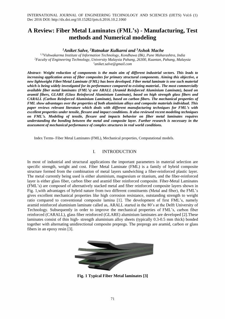
Fig. 2 gives a classification of FML based on metal plies. The most commercially available FML’s
are ARALL1, based on aramid fibers and GLARE1 based on high strength glass fibers.
Fig 2: Typical Classes of FML’s 1.1 Advantages, Disadvantages and Applications of FML’s
Due to the combination of metal and composite material, FML’s take advantages of metal and fiber-
reinforced composites; it gives superior mechanical properties to the conventional lamina which
consisting fiber-reinforced lamina or monolithic aluminium alloys only. Advantages of fiber metal
laminates depending on previous investigations are summarized in Table 1. Long processing cycle to
cure the matrix in composite plies is the major disadvantage associated with epoxy based fiber metal
laminates. This long curing time increases the cycle time of whole production and decreases
productivity. Ultimately increases labour costs and overall cost of FMLs [4-6].
Table 1. Advantage of fiber metal laminates Key Parameters Ref. Details
High strength [4,5] FML’s are hybrid structures based on thin metal alloy sheets and plies of
fiber-reinforced polymeric materials. Metal and fiber reinforced
composites both which have high strength and stiffness result in high
strength and stiffness FML’s.
Low density [7] Due to the presence of thin layers of metals and composite piles, it has
low density. So, FML’s are a weight saving structural material compare
to others.
Excellent corrosion
resistance
[7-10] FML’s gives excellent moisture resistance and high corrosion resistance
because of polymer based.
Excellent moisture
resistance
[1,10] Due to the presence of metal layers at outer surface the moisture
absorption in FML’s composites is slower when compared with polymer
composites, even under the relatively harsh conditions. Additionally
pregreg layers are able to act as moisture barriers between the various
aluminium layers inside of the FML’s.
High fatigue resistance [5,10] It gives high fatigue resistance because of intact bridging fibers in the
wake of the crack, which restrain crack opening. FML’s have excellent
fatigue characteristics over conventional metal and composite.
High energy absorbing
capacity
[6,10] Based on investigation data, FML’s are absorbing significant energy
through localized fiber fracture and shear failure in the metal plies.
High impact resistance [8,11] Impact deformation is actually a significant advantage of FML’s,
especially when compared to composites.
Fiber Metal Laminates (FML’s)
Other Metal based
Fiber metal laminates
ARALL
Aluminium based
Fiber metal laminates
Titanium
based FMl’s
Magnesium
based FML’s
Steel
based FML’s
GLARE CARALL
ARALL 1
ARALL 2
ARALL 3
ARALL 3
GLARE 1
GLARE 2
GLARE 3
GLARE 4
GLARE 5
CARALL 2
CARALL 1
INTERNATIONAL JOURNAL OF ENGINEERING TECHNOLOGY AND SCIENCES (IJETS) Vol.6 (1)
Dec 2016 DOI: http://dx.doi.org/10.15282/ijets.6.2016.10.2.1060
73
Above advantages of FML’s finds great use in aerospace and automobile applications. Now a day’s
most of companies have interest in aluminium components by FML’s composites. ARALL and
GLARE laminates are now being used as structural materials for manufacturing aircrafts. Fiber Metal
Laminates have been effectively used into the Airbus A380 [4, 5].
In spite of mentioned advantages of FML’s their properties still need more understanding and
attention. Although many articles have been published regarding to mechanical properties of FML’s,
the research on this part of FML’s performance is still in the early stages. There are several issues to
be addressed related to the modeling and experimental investigation of FML’s. The purpose of this
paper is to review relevant literature related to different manufacturing techniques, properties of
FML’s and numerical modeling. During this review, the key technical issues that need to be solved in
future are also addressed.
II. MANUFACTURING OF FML’s
2.1 Manufacturing of Fiber Meta laminates (FML):
The most common process used to produce FML’s, as for polymeric composite materials, involves
the use of autoclave processing. The overall production of FML’s composite involves following major
steps [7, 11-13].
During this step, the surface of metal layer is pre-treated by acidic solution e.g. chromic acid or
phosphoric acid, in order to improve the bond between the adhesive system and the metal surface.
Applying resin uniformly over metal plates and reinforced material as glass or carbon fiber by using
hand layup.
Applying uniform pressure by compression moulding machine or vacuum bag techniques.
After that cure process takes place which, including the flow-consolidation process, the chemical
curing reactions, as well as the bond between fiber/metal layers.
Last step consists of Inspection, which is done usually by ultrasound, X ray, visual techniques and
mechanical tests.
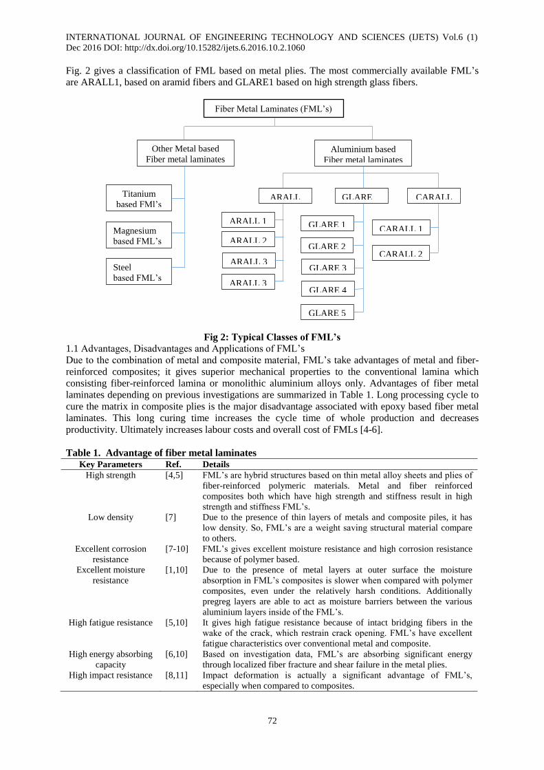
The cure preparation step involves primarily the bagging of the part and the placement of many
ancillary materials. The common cure preparation arrangements, including the part, the tool, the
bagging are shown in Fig 3.
Fig 3. Schematic Representation of Vacuum bag system [14]
Recent investigation has shown that manufacturing of FML’s by Resin Transfer Moulding (RTM)
could also be a possibility. This manufacturing process is a family of closed-mould low-pressure
processes that allow the fabrication of composites ranging in complexity from simple, low
performance to complex high performance articles and in size from small to very large. The common
feature of all the resin transfer moulding processes is the flow of resin material through the unwetted
fibers. During the injection of the resin a pressure difference is applied in the closed mould, which
forces the resin to flow through the reinforcement. Therefore the permeability of the reinforcement is
an important factor. The process is typically used with low viscosity fast-curing resins, such as
polyester, epoxy and chopped or continuous mat reinforcement at low fiber volume content. However,
the process has been demonstrated with higher fiber volume contents (50 to 60%) [15].
INTERNATIONAL JOURNAL OF ENGINEERING TECHNOLOGY AND SCIENCES (IJETS) Vol.6 (1)
Dec 2016 DOI: http://dx.doi.org/10.15282/ijets.6.2016.10.2.1060
74
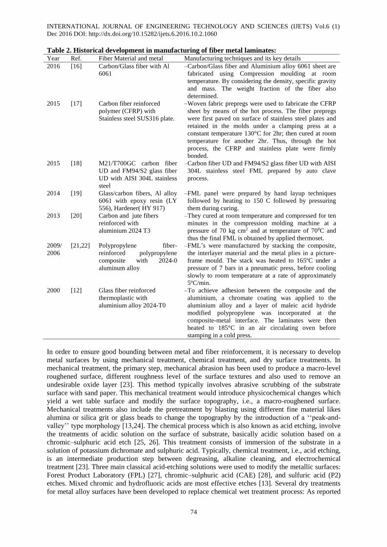
Table 2. Historical development in manufacturing of fiber metal laminates: Year Ref. Fiber Material and metal Manufacturing techniques and its key details
2016 [16] Carbon/Glass fiber with Al
6061
–Carbon/Glass fiber and Aluminium alloy 6061 sheet are
fabricated using Compression moulding at room
temperature. By considering the density, specific gravity
and mass. The weight fraction of the fiber also
determined.
2015 [17] Carbon fiber reinforced
polymer (CFRP) with
Stainless steel SUS316 plate.
–Woven fabric prepregs were used to fabricate the CFRP
sheet by means of the hot process. The fiber prepregs
were first paved on surface of stainless steel plates and
retained in the molds under a clamping press at a
constant temperature 130°C for 2hr; then cured at room
temperature for another 2hr. Thus, through the hot
process, the CFRP and stainless plate were firmly
bonded.
2015 [18] M21/T700GC carbon fiber
UD and FM94/S2 glass fiber
UD with AISI 304L stainless
steel
–Carbon fiber UD and FM94/S2 glass fiber UD with AISI
304L stainless steel FML prepared by auto clave
process.
2014 [19] Glass/carbon fibers, Al alloy
6061 with epoxy resin (LY
556), Hardener( HY 917)
–FML panel were prepared by hand layup techniques
followed by heating to 150 C followed by pressuring
them during curing.
2013 [20] Carbon and jute fibers
reinforced with
aluminium 2024 T3
–They cured at room temperature and compressed for ten
minutes in the compression molding machine at a
pressure of 70 kg cm2 and at temperature of 700C and
thus the final FML is obtained by applied thermoset.
2009/
2006
[21,22] Polypropylene fiber-
reinforced polypropylene
composite with 2024-0
aluminum alloy
–FML’s were manufactured by stacking the composite,
the interlayer material and the metal plies in a picture-
frame mould. The stack was heated to 165ºC under a
pressure of 7 bars in a pneumatic press, before cooling
slowly to room temperature at a rate of approximately
5ºC/min.
2000 [12] Glass fiber reinforced
thermoplastic with
aluminium alloy 2024-T0
–To achieve adhesion between the composite and the
aluminium, a chromate coating was applied to the
aluminium alloy and a layer of maleic acid hydride
modified polypropylene was incorporated at the
composite-metal interface. The laminates were then
heated to 185°C in an air circulating oven before
stamping in a cold press.
In order to ensure good bounding between metal and fiber reinforcement, it is necessary to develop
metal surfaces by using mechanical treatment, chemical treatment, and dry surface treatments. In
mechanical treatment, the primary step, mechanical abrasion has been used to produce a macro-level
roughened surface, different roughness level of the surface textures and also used to remove an
undesirable oxide layer [23]. This method typically involves abrasive scrubbing of the substrate
surface with sand paper. This mechanical treatment would introduce physicochemical changes which
yield a wet table surface and modify the surface topography, i.e., a macro-roughened surface.
Mechanical treatments also include the pretreatment by blasting using different fine material likes
alumina or silica grit or glass beads to change the topography by the introduction of a ‘‘peak-and-
valley’’ type morphology [13,24]. The chemical process which is also known as acid etching, involve
the treatments of acidic solution on the surface of substrate, basically acidic solution based on a
chromic–sulphuric acid etch [25, 26]. This treatment consists of immersion of the substrate in a
solution of potassium dichromate and sulphuric acid. Typically, chemical treatment, i.e., acid etching,
is an intermediate production step between degreasing, alkaline cleaning, and electrochemical
treatment [23]. Three main classical acid-etching solutions were used to modify the metallic surfaces:
Forest Product Laboratory (FPL) [27], chromic–sulphuric acid (CAE) [28], and sulfuric acid (P2)
etches. Mixed chromic and hydrofluoric acids are most effective etches [13]. Several dry treatments
for metal alloy surfaces have been developed to replace chemical wet treatment process: As reported

INTERNATIONAL JOURNAL OF ENGINEERING TECHNOLOGY AND SCIENCES (IJETS) Vol.6 (1)
Dec 2016 DOI: http://dx.doi.org/10.15282/ijets.6.2016.10.2.1060
75
in Ref. [23], laser texturing was utilized to modify an aluminium substrate’s morphology and micro-
structure, resulting in an increased bond strength and durability. Ion beam enhanced deposition
(IBED) is a process that cleans and modifies the surface by sputtering with high energy argon ions
under vacuum. In ion beam enhanced deposition (IBED) requires a surface activation step,
particularly grit-blasting, prior to IBED. Good initial bond strengths were obtained and the
improvements in wedge durability compared with peracetic acid (PAA) were found [13].
III. TEST METHODS OF FML’s COMPOSITES
Parameters that influence the response characteristics of FML’s are a. Type of metal. b. Type of fiber.
c. Type of matrix. d. Metal/Composite volume fraction. e. Bonding/Surface treatment etc. Mechanical
properties of FML’s are being enhanced by the interface bond between composite and metal plies.
This enhancement could be controlled by various test methods. This test reports give quality
information and are suitable for design specifications. In this review; test methods of bending
(flexural), fatigue, tensile, low and high velocity impact tests for determining the mechanical
properties of FMLs and research studies utilized from these test methods were explained.
3.1 Flexural Test:
Mechanical properties of FML’s composite are derived by the adhesion between fiber and matrix.
Beside this, same properties of FML’s are also depends on the interface bond between composite ply
and metal ply. It is very difficult task to determine this adhesion, therefore various test methods have
been proposed for this purpose: inter laminar shear and interfacial fracture tests. These methods give
quality control information and not suitable for design specifications.
Flexural properties, such as flexural strength and modulus, are determined by ASTM test method
D790. In this test, a composite beam specimen of rectangular cross section is loaded in either a three-
point bending mode or a four-point bending mode or five point bending mode shown in fig. 4 [12, 28-
30] In either mode, a large span–thickness (L=h) ratio is recommended. Three point flexural tests
have received wide acceptance in the composite material industry because the specimen preparation
and fixtures are very simple. Beside this few limitations should be recognized. However; Khalili et al.
[30] reported that three-point bending tests were carried out on Zwick 1484 by using specifications of
ASTM D790 M-93. J.G. Carrillo et al. [21] conducted flexural test on four points bending test and
reported that fiber orientation had only a secondary effect on the properties of the FML.
Fig 4. Photograph of a three, four and five point bending test. [13, 21]
3.2 Shear Test:
A variety of test methods [31, 32] have been used for measuring in plane shear properties, such as the
shear modulus and the ultimate shear strength of unidirectional fiber reinforced composites.
According to the literature survey, there are three kinds of in plane shear for measuring these two
properties. 1. ±45 Shear test 2. 100Off-axis test 3. Iosipescu shear test [33,34]. Hinz et al. [35]
investigated experimentally inter laminar shear properties of FMLs by double-notch shear test (DNS)
according to ASTM D3846 at room temperature. Inter laminar shear load between the notches was
primarily applied by compression on both ends of the DNS specimen.
INTERNATIONAL JOURNAL OF ENGINEERING TECHNOLOGY AND SCIENCES (IJETS) Vol.6 (1)
Dec 2016 DOI: http://dx.doi.org/10.15282/ijets.6.2016.10.2.1060
76
Lawcock et al. [29] reported the inter laminar shear test of FMLs by three and five point bending tests
with a span of 10 mm at a crosshead speed of 1.3 mm/min. These tests were undertaken at
displacement rates between 0.1 and 3 m/s and were stopped once a visible crack had propagated from
one of the starter defects.
3.3 Fatigue Test:
Fatigue behavior of a material is usually characterized by an S–N diagram, which shows the
relationship between the stress amplitude or maximum stress and number of cycles to failure on a
semi logarithmic scale. This diagram is obtained by testing a number of specimens at various stress
levels under sinusoidal loading conditions. The majority of fatigue tests on fiber-reinforced composite
materials have been performed with uniaxial tension–tension cycling. Tension– compression and
compression–compression cycling are not commonly used since failure by compressive buckling may
occur in thin laminates. Completely reversed tension–compression cycling is achieved by flexural
fatigue tests. The tension–tension fatigue cycling test procedure is described in ASTM D347 [10, 36].
It uses a straight-sided specimen with the same dimensions and end tabs as in static tension tests.
Apart from this Kanga et al. [37] performed ASTM E466 test for fatigue behavior of FML. Many
research papers reported fatigue test based on the specimens prepared as notched or cracked for
initiation of crack. All fatigue tests were conducted with constant amplitude in tension–tension or
tension–compression loading at a frequency of 10 Hz at room temperature [10, 38-42]. Beside this in
some researchers conducting fatigue test with sinusoidal waves of frequency 5 Hz [43, 44].
3.4 Tensile Test:
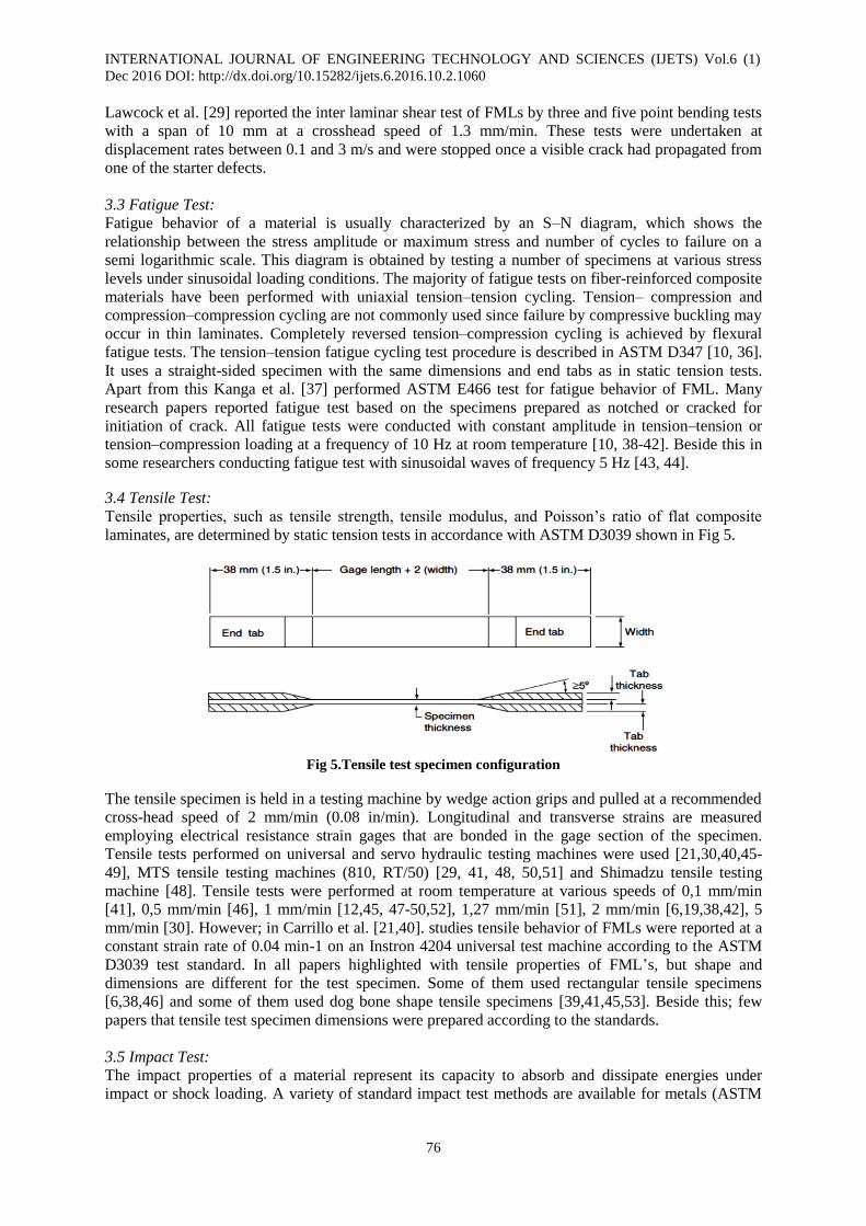
Tensile properties, such as tensile strength, tensile modulus, and Poisson’s ratio of flat composite
laminates, are determined by static tension tests in accordance with ASTM D3039 shown in Fig 5.
Fig 5.Tensile test specimen configuration
The tensile specimen is held in a testing machine by wedge action grips and pulled at a recommended
cross-head speed of 2 mm/min (0.08 in/min). Longitudinal and transverse strains are measured
employing electrical resistance strain gages that are bonded in the gage section of the specimen.
Tensile tests performed on universal and servo hydraulic testing machines were used [21,30,40,45-
49], MTS tensile testing machines (810, RT/50) [29, 41, 48, 50,51] and Shimadzu tensile testing
machine [48]. Tensile tests were performed at room temperature at various speeds of 0,1 mm/min
[41], 0,5 mm/min [46], 1 mm/min [12,45, 47-50,52], 1,27 mm/min [51], 2 mm/min [6,19,38,42], 5
mm/min [30]. However; in Carrillo et al. [21,40]. studies tensile behavior of FMLs were reported at a
constant strain rate of 0.04 min-1 on an Instron 4204 universal test machine according to the ASTM
D3039 test standard. In all papers highlighted with tensile properties of FML’s, but shape and
dimensions are different for the test specimen. Some of them used rectangular tensile specimens
[6,38,46] and some of them used dog bone shape tensile specimens [39,41,45,53]. Beside this; few
papers that tensile test specimen dimensions were prepared according to the standards.
3.5 Impact Test:
The impact properties of a material represent its capacity to absorb and dissipate energies under
impact or shock loading. A variety of standard impact test methods are available for metals (ASTM
INTERNATIONAL JOURNAL OF ENGINEERING TECHNOLOGY AND SCIENCES (IJETS) Vol.6 (1)
Dec 2016 DOI: http://dx.doi.org/10.15282/ijets.6.2016.10.2.1060
77
E23) and unreinforced polymers (ASTM D256). Basically low and high velocity test should be
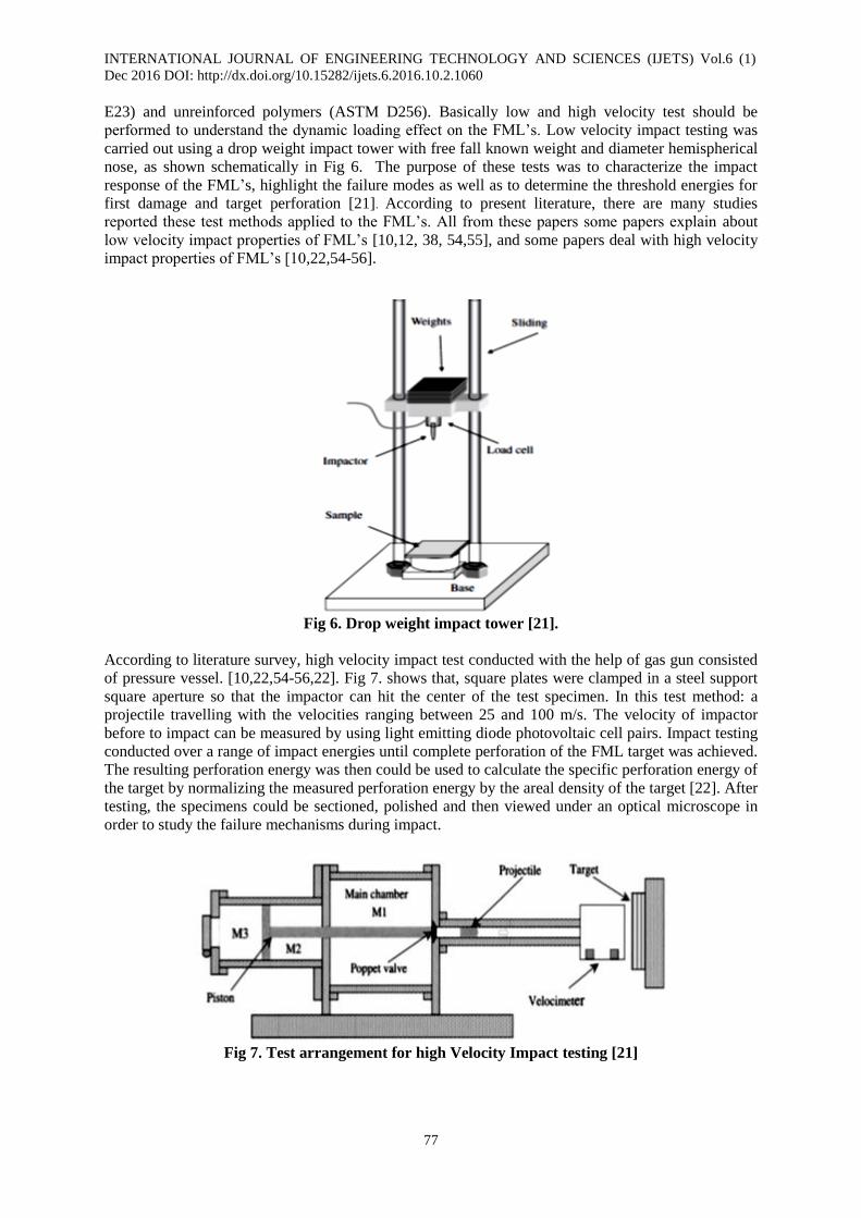
performed to understand the dynamic loading effect on the FML’s. Low velocity impact testing was
carried out using a drop weight impact tower with free fall known weight and diameter hemispherical
nose, as shown schematically in Fig 6. The purpose of these tests was to characterize the impact
response of the FML’s, highlight the failure modes as well as to determine the threshold energies for
first damage and target perforation [21]. According to present literature, there are many studies
reported these test methods applied to the FML’s. All from these papers some papers explain about
low velocity impact properties of FML’s [10,12, 38, 54,55], and some papers deal with high velocity
impact properties of FML’s [10,22,54-56].
Fig 6. Drop weight impact tower [21].
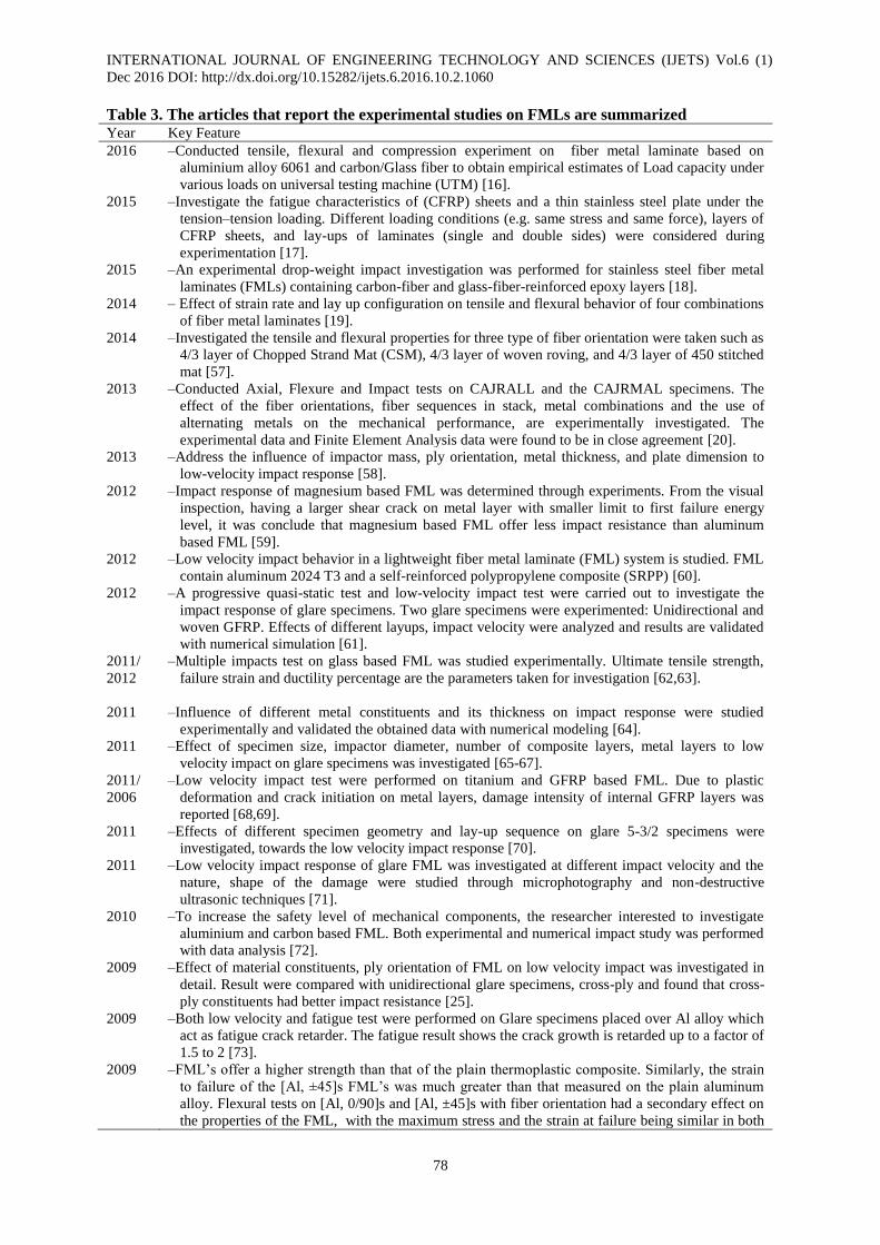
According to literature survey, high velocity impact test conducted with the help of gas gun consisted
of pressure vessel. [10,22,54-56,22]. Fig 7. shows that, square plates were clamped in a steel support
square aperture so that the impactor can hit the center of the test specimen. In this test method: a
projectile travelling with the velocities ranging between 25 and 100 m/s. The velocity of impactor
before to impact can be measured by using light emitting diode photovoltaic cell pairs. Impact testing
conducted over a range of impact energies until complete perforation of the FML target was achieved.
The resulting perforation energy was then could be used to calculate the specific perforation energy of
the target by normalizing the measured perforation energy by the areal density of the target [22]. After
testing, the specimens could be sectioned, polished and then viewed under an optical microscope in
order to study the failure mechanisms during impact.
Fig 7. Test arrangement for high Velocity Impact testing [21]
INTERNATIONAL JOURNAL OF ENGINEERING TECHNOLOGY AND SCIENCES (IJETS) Vol.6 (1)
Dec 2016 DOI: http://dx.doi.org/10.15282/ijets.6.2016.10.2.1060
78
Table 3. The articles that report the experimental studies on FMLs are summarized Year Key Feature
2016 –Conducted tensile, flexural and compression experiment on fiber metal laminate based on
aluminium alloy 6061 and carbon/Glass fiber to obtain empirical estimates of Load capacity under
various loads on universal testing machine (UTM) [16].
2015 –Investigate the fatigue characteristics of (CFRP) sheets and a thin stainless steel plate under the
tension–tension loading. Different loading conditions (e.g. same stress and same force), layers of
CFRP sheets, and lay-ups of laminates (single and double sides) were considered during
experimentation [17].
2015 –An experimental drop-weight impact investigation was performed for stainless steel fiber metal
laminates (FMLs) containing carbon-fiber and glass-fiber-reinforced epoxy layers [18].
2014 – Effect of strain rate and lay up configuration on tensile and flexural behavior of four combinations
of fiber metal laminates [19].
2014 –Investigated the tensile and flexural properties for three type of fiber orientation were taken such as
4/3 layer of Chopped Strand Mat (CSM), 4/3 layer of woven roving, and 4/3 layer of 450 stitched
mat [57].
2013 –Conducted Axial, Flexure and Impact tests on CAJRALL and the CAJRMAL specimens. The
effect of the fiber orientations, fiber sequences in stack, metal combinations and the use of
alternating metals on the mechanical performance, are experimentally investigated. The
experimental data and Finite Element Analysis data were found to be in close agreement [20].
2013 –Address the influence of impactor mass, ply orientation, metal thickness, and plate dimension to
low-velocity impact response [58].
2012 –Impact response of magnesium based FML was determined through experiments. From the visual
inspection, having a larger shear crack on metal layer with smaller limit to first failure energy
level, it was conclude that magnesium based FML offer less impact resistance than aluminum
based FML [59].
2012 –Low velocity impact behavior in a lightweight fiber metal laminate (FML) system is studied. FML
contain aluminum 2024 T3 and a self-reinforced polypropylene composite (SRPP) [60].
2012 –A progressive quasi-static test and low-velocity impact test were carried out to investigate the
impact response of glare specimens. Two glare specimens were experimented: Unidirectional and
woven GFRP. Effects of different layups, impact velocity were analyzed and results are validated
with numerical simulation [61].
2011/
2012
–Multiple impacts test on glass based FML was studied experimentally. Ultimate tensile strength,
failure strain and ductility percentage are the parameters taken for investigation [62,63].
2011 –Influence of different metal constituents and its thickness on impact response were studied
experimentally and validated the obtained data with numerical modeling [64].
2011 –Effect of specimen size, impactor diameter, number of composite layers, metal layers to low
velocity impact on glare specimens was investigated [65-67].
2011/
2006
–Low velocity impact test were performed on titanium and GFRP based FML. Due to plastic
deformation and crack initiation on metal layers, damage intensity of internal GFRP layers was
reported [68,69].
2011 –Effects of different specimen geometry and lay-up sequence on glare 5-3/2 specimens were
investigated, towards the low velocity impact response [70].
2011 –Low velocity impact response of glare FML was investigated at different impact velocity and the
nature, shape of the damage were studied through microphotography and non-destructive
ultrasonic techniques [71].
2010 –To increase the safety level of mechanical components, the researcher interested to investigate
aluminium and carbon based FML. Both experimental and numerical impact study was performed
with data analysis [72].
2009 –Effect of material constituents, ply orientation of FML on low velocity impact was investigated in
detail. Result were compared with unidirectional glare specimens, cross-ply and found that cross-
ply constituents had better impact resistance [25].
2009 –Both low velocity and fatigue test were performed on Glare specimens placed over Al alloy which
act as fatigue crack retarder. The fatigue result shows the crack growth is retarded up to a factor of
1.5 to 2 [73].
2009 –FML’s offer a higher strength than that of the plain thermoplastic composite. Similarly, the strain
to failure of the [Al, ±45]s FML’s was much greater than that measured on the plain aluminum
alloy. Flexural tests on [Al, 0/90]s and [Al, ±45]s with fiber orientation had a secondary effect on
the properties of the FML, with the maximum stress and the strain at failure being similar in both
INTERNATIONAL JOURNAL OF ENGINEERING TECHNOLOGY AND SCIENCES (IJETS) Vol.6 (1)
Dec 2016 DOI: http://dx.doi.org/10.15282/ijets.6.2016.10.2.1060
79
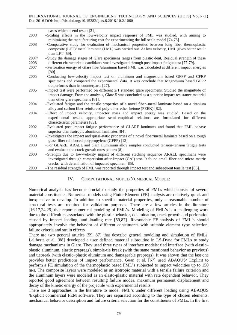
cases which is end result [21].
2008 –Scaling effects in the low-velocity impact response of FML was studied, with aiming to
minimizing the manufacturing cost for experimenting the full scale model [74,75].
2008 –Comparative study for evaluation of mechanical properties between long fiber thermoplastic
composite (LFT)/ metal laminate (LML) was carried out. At low velocity, LML gives better result
than LFT [59].
2007/
2008
–Study the damage stages of Glare specimens ranges from plastic dent, Residual strength of these
different characteristic candidates was investigated through post impact fatigue test [77-79].
2007 –Perforation energy of Glare fiber/aluminum based FML was calculated at different impact energies
[80].
2005 –Conducting low-velocity impact test on aluminum and magnesium based GFPP and CFRP
specimens and compared the experimental data. It was conclude that Magnesium based GFPP
outperforms than its counterparts [27].
2005 –Impact test were performed on different 2/1 standard glare specimens. Studied the magnitude of
impact damage. From the analysis, Glare 5 was concluded as a superior impact resistance material
than other glare specimens [81].
2004 –Evaluated fatigue and the tensile properties of a novel fiber–metal laminate based on a titanium
alloy and carbon fiber-reinforced poly-ether-ether-ketone (PEEK) [82].
2004 –Effect of impact velocity, impactor mass and impact energy was studied. Based on the
experimental result, appropriate semi–empirical relations are formulated for different
characteristic parameters [83].
2002 –Evaluated post impact fatigue performance of GLARE laminates and found that FML behave
superior than isotropic aluminum laminates [84].
2000 –Investigates the impact and quasi-static properties of a novel fiber/metal laminate based on a tough
glass-fiber reinforced polypropylene (GFPP) [12].
2000 –For GLARE, ARALL and plain aluminium alloy samples conducted tension-tension fatigue tests
and evaluate the crack growth rates pattern [8].
2000 –Strength due to low-velocity impact of different stacking sequence ARALL specimens were
investigated through compression after Impact (CAI) test. It found small fiber and micro matric
cracks, with delamination of impacted specimen [85].
2000 –The residual strength of FML was reported through Impact test and subsequent tensile test [86].
IV. COMPUTATIONAL MODEL/NUMERICAL MODEL:
Numerical analysis has become crucial to study the properties of FMLs which consist of several
material constituents. Numerical models using Finite-Element (FE) analysis are relatively quick and
inexpensive to develop. In addition to specific material properties, only a reasonable number of
structural tests are required for validation purposes. There are a few articles in the literature
[16,17,24,25] that report numerical modeling of FML’s. Modeling of FML’s is a challenging work
due to the difficulties associated with the plastic behavior, delamination, crack growth and perforation
caused by impact loading, and loading rate [59,87]. Reasonable FE-analysis of FML’s should
appropriately involve the behavior of different constituents with suitable element type selection,
failure criteria and strain effects.
There are two general articles [59, 87] that describe general modeling and simulation of FMLs.
Laliberte et al. [88] developed a user defined material subroutine in LS-Dyna for FMLs to study
damage mechanisms in Glare. They used three types of interface models: tied interface (with elastic–
plastic aluminum, elastic prepregs), simple-tie break (with the same mentioned behavior as previous)
and tiebreak (with elastic–plastic aluminum and damageable prepregs). It was shown that the last one
provides better predictions of impact performance. Guan et al. [67] used ABAQUS/ Explicit to
perform a FE simulation of the thermoplastic based FML’s subjected to impact velocities up to 150
m/s. The composite layers were modeled as an isotropic material with a tensile failure criterion and
the aluminum layers were modeled as an elasto-plastic material with rate dependent behavior. They
reported good agreement between resulting failure modes, maximum permanent displacement and
decay of the kinetic energy of the projectile with experimental results.
There are 3 approaches in the literature to model FML’s under different loading using ABAQUS
/Explicit commercial FEM software. They are separated according to the type of chosen elements,
mechanical behavior description and failure criteria selection for the constituents of FMLs. In the first
INTERNATIONAL JOURNAL OF ENGINEERING TECHNOLOGY AND SCIENCES (IJETS) Vol.6 (1)
Dec 2016 DOI: http://dx.doi.org/10.15282/ijets.6.2016.10.2.1060
80
approach [67], solid elements were used for both metal (most of the time aluminum) and composite
layers. The aluminum alloy was modeled as an elasto-plastic material with rate-dependent behavior,
whereas the composite was modeled as an isotropic material. Both shear and tensile failure criteria
were used to simulate the failure processes in the aluminum layers and a similar tensile failure
criterion used for the composite layers. The second approach [24] used 8-node solid element (C3D8R)
and 8-node shell element (SC8R) for the aluminum alloy and composite layers, respectively. In the
implemented model, the Hashin damage initiation criteria were used for the composite layers and no
damage criterion was applied to the aluminum sheets. However, due to the fact that realistic modeling
of layers and interface between the metal and fiber-reinforced polymer layers requires through-
thickness stresses, shell elements with plane-stress assumption are not suitable for composite layers
[27]. On the other hand, the failure criteria included in ABAQUS for composite layers are only
applicable to continuum shell elements with plane stress conditions. Therefore, in the last approach,
Seo et al. [27] developed a user material subroutine VUMAT to simulate progressive damage and
failure of composite layers with three-dimensional solid-elements [64].
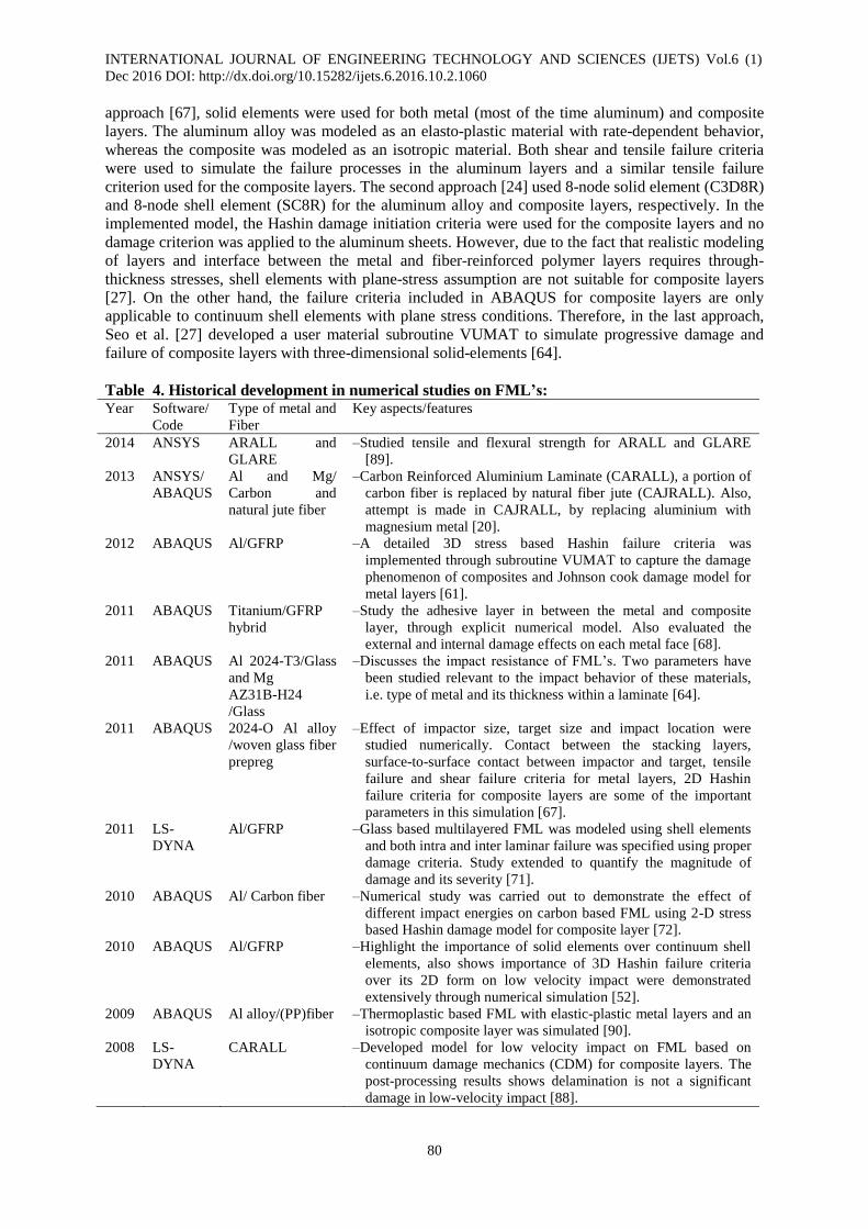
Table 4. Historical development in numerical studies on FML’s: Year Software/
Code
Type of metal and
Fiber
Key aspects/features
2014 ANSYS ARALL and
GLARE
–Studied tensile and flexural strength for ARALL and GLARE
[89].
2013 ANSYS/
ABAQUS
Al and Mg/
Carbon and
natural jute fiber
–Carbon Reinforced Aluminium Laminate (CARALL), a portion of
carbon fiber is replaced by natural fiber jute (CAJRALL). Also,
attempt is made in CAJRALL, by replacing aluminium with
magnesium metal [20].
2012 ABAQUS Al/GFRP –A detailed 3D stress based Hashin failure criteria was
implemented through subroutine VUMAT to capture the damage
phenomenon of composites and Johnson cook damage model for
metal layers [61].
2011 ABAQUS Titanium/GFRP
hybrid
–Study the adhesive layer in between the metal and composite
layer, through explicit numerical model. Also evaluated the
external and internal damage effects on each metal face [68].
2011 ABAQUS Al 2024-T3/Glass
and Mg
AZ31B-H24
/Glass
–Discusses the impact resistance of FML’s. Two parameters have
been studied relevant to the impact behavior of these materials,
i.e. type of metal and its thickness within a laminate [64].
2011 ABAQUS 2024-O Al alloy
/woven glass fiber
prepreg
–Effect of impactor size, target size and impact location were
studied numerically. Contact between the stacking layers,
surface-to-surface contact between impactor and target, tensile
failure and shear failure criteria for metal layers, 2D Hashin
failure criteria for composite layers are some of the important
parameters in this simulation [67].
2011 LS-
DYNA
Al/GFRP –Glass based multilayered FML was modeled using shell elements
and both intra and inter laminar failure was specified using proper
damage criteria. Study extended to quantify the magnitude of
damage and its severity [71].
2010 ABAQUS Al/ Carbon fiber –Numerical study was carried out to demonstrate the effect of
different impact energies on carbon based FML using 2-D stress
based Hashin damage model for composite layer [72].
2010 ABAQUS Al/GFRP –Highlight the importance of solid elements over continuum shell
elements, also shows importance of 3D Hashin failure criteria
over its 2D form on low velocity impact were demonstrated
extensively through numerical simulation [52].
2009 ABAQUS Al alloy/(PP)fiber –Thermoplastic based FML with elastic-plastic metal layers and an
isotropic composite layer was simulated [90].
2008 LS-
DYNA
CARALL –Developed model for low velocity impact on FML based on
continuum damage mechanics (CDM) for composite layers. The
post-processing results shows delamination is not a significant
damage in low-velocity impact [88].
INTERNATIONAL JOURNAL OF ENGINEERING TECHNOLOGY AND SCIENCES (IJETS) Vol.6 (1)
Dec 2016 DOI: http://dx.doi.org/10.15282/ijets.6.2016.10.2.1060
81
V. CONCLUSION
A vast number of available literatures showed that FML’s have great potential in aerospace as well as
automobile applications. It is found in many cases that FML’s are superior mechanical properties
compared to conventional aluminum alloy or fiber reinforced polymer composites. Excellent fatigue
characteristics, high modulus of elasticity with improved toughness, high strength to weight ratio are
major advantages of FML’s. In this review paper different manufacturing techniques and test methods
with numerical modeling for FML’s are reviewed. An adequate manufacturing process and good
surface treatment of FML’s is required to get a good mechanical and adhesive bond between the
composite laminates and adjacent metal layer. Surface treatment methods are discussed and showed
comparable performance to improve the FML’s. In this review; test methods such as tensile, flexural,
shear, fatigue and low and high velocity impact for determining the mechanical properties of FML’s.
The performance of the FML’s depends on type of metal, types of fiber, matrix materials,
metal/composite volume fraction and bonding/surface treatment etc. Experimental work on FML’s is
expensive and time consuming. So, numerical analyses become very effective and crucial to study the
mechanical behavior of FML’s. ABAQUS and LS-DYNA are the two most explicit codes used by
many researchers for numerical modeling and validation purposes. Most of researchers study the
modeling of impact behavior which required knowledge of plasticity, fracture mechanics and damage
mechanics. Currently a lot of research is needed to improve the methodology used to study the
material and further expand the possibilities of applications. There are many study required regarding
the structural and material mechanics within the FML’s.
VI. FUTURE DEVELOPMENT
1. Comparative study is essential on the mechanical behavior of FML’s based on thermoset and
thermoplastics matrices.
2. Comparative study required in arrangement and configuration of constituents within FML’s
and their influences on the mechanical properties.
3. Study required under thermal circumstances.
4. Specimen with different geometries and boundary condition which matches with the real
world conditions required to study the mechanical performance.
VII. REFERENCES
[1] Botelho E.C., Silva R.A., Pardini L.C., Rezende M.C.,“A review on the development and properties of
continuous fiber/epoxy/aluminum hybrid composites for aircraft structures”, Mater Res,9(3), pp. 247–56,
2006.
[2] Marissen R., Vogelesang LB, ”Development of a new hybrid material: aramid reinforced aluminium
laminate (Arall)”, SAMPE Conference, Cannes, 1981.
[3] M. Sadighi, R.C., Alderliesten, R. Benedictus., “Impact resistance of fiber-metal laminates: A review”
International Journal of Impact Engineering 49, pp. 77-90, (2012)
[4] Beumler T, Pellenkoft F, Tillich A, Wohlers W, Smart C,.”Airbus costumer benefit from fiber metal
laminates”, Airbus Deutschland GmbH; Ref. no: L53pr0605135-Issue 1, pp. 1–18, 2006 May.
[5] Alderliesten R.C., Benedictus R., ”Fiber/metal composite technology for future primary aircraft structures”,
In: 48th Aiaa/Asme/Asce/Ahs/Asc structures, structural dynamics, and materials conference 15th, Honolulu,
Hawaii, pp 1–12, April 23–26, 2007.
[6] Cortes P., Cantwell WJ, ”The prediction of tensile failure in titanium-based thermoplastic fibre metal
laminates”, Compos Sci Technol, 66, pp.2306–16, 2006.
[7] Gutowski TG., ”Advanced Composites Manufacturing”, First edition, John Wiley & Sons, New York, USA,
1997.
[8] Vogelesang LB, Vlot A., “Development of fiber metal laminates for advanced”, J Mater Process Technol,
103, pp.1–5, 2000.
[9] Alderliesten R. “On the development of hybrid material concepts for aircraft structures”, Recent Patents Eng,
3, pp.25-38, 2009.
[10] Vlot A., ”Impact loading on fibre metal laminates”, Int J Impact Eng,18(3), pp.291–307,1996. [11] Vlot A.,Gunnink JW., ”Fibre Metal Laminates”, Kluwer Academic Publishers, Dordrecht, The Netherlands,
2001.
INTERNATIONAL JOURNAL OF ENGINEERING TECHNOLOGY AND SCIENCES (IJETS) Vol.6 (1)
Dec 2016 DOI: http://dx.doi.org/10.15282/ijets.6.2016.10.2.1060
82
[12] Reyes Villanueva G, Cantwell WJ, ”The mechanical properties of fibre-metal laminates based on glass
fibre reinforced polypropylene”, Compos Sci Technol,60(7), pp.1085-94,2000.
[13] Tamer Sinmazçelik, Egemen Avcu, Mustafa Özgür Bora, Onur Çoban.,”A review: Fibre metal laminates,
background, bonding types and applied test methods”, Composite Structures, 107, pp.363–381, 2014.
[14] Edson Cocchieri Botelho, Rogério Almeida Silva.,” A Review on the Development and Properties of
Continuous Fiber/epoxy/aluminum Hybrid Composites for Aircraft Structures”, Materials Research, Vol. 9,
No. 3, pp.247-256, 2006.
[15] Volt, Jan Willem,” Fiber metal laminates-Introduction”, Springer- Science+ Business Media, B,V. ISBN
978-1-4020-0391-2,2001.
[16] Hariharan E., Prof. R.Santhana Krishnan,” Experimental analysis of fiber metal laminates with aluminium
alloy for aircraft structures”, IJESRT, ISSN: 2277-9655, May 2016.
[17] Qiang Liu, Jingbo Ma, Lan Kang, Guangyong Sun, Qing Li,” An experimental study on fatigue
characteristics of CFRP-steel hybrid laminates”, Materials and Design 88, pp.643–650,2015.
[18] T. Pärnänen, M. Kanerva, E. Sarlin, O. Saarela, “Debonding and impact damage in stainless steel fibre
metal laminates prior to metal fracture”, Composite Structures 119, pp.777–786,2015.
[19] G.R. Rajkumar, M. Krishna, “Investigation of tensile and bending behavior of aluminium base hybrid fiber
metal laminates”, International conference of advance in manufacturing and materials engineering (AMME
-2014), Procedia of material science,5, pp.60-68,2014.
[20] M.Vasumathi, Vela Murali, “Effect of alternate metals for use in natural fiber reinforced fiber metal
laminates under bending, impact and axial loadings”, International Conference on Design and
Manufacturing, IConDM-2013, Procedia Engineering, 64, pp.562-570, 2013.
[21] Carrillo JG, Cantwell WJ., ”Mechanical properties of a novel fiber–metal laminate based on a
polypropylene composite”, Mech Mater,41, pp.828–38,2009.
[22] Abdullah MR., Cantwell WJ.,” The impact resistance of polypropylene-based fibre–metal laminates”,
Compos Sci Technology, 66, pp.1682–93, 2006.
[23] Park SY, Choi WJ, Choi HS, Kwon H, Kim SH, ”Recent trends in surface treatment technologies for
airframe adhesive bonding processing: a review”, J Adhes, 86, pp.192–221, 2010.
[24] Critchlow GW, Yendall KA, Bahrani D, Quinn A, Andrews F., ”Strategies for the replacement of chromic
acid anodising for the structural bonding of aluminium alloys”, Int J Adhes, 26, pp.419–53,2006.
[25] Critchlow GW, Brewis DM.,” Review of surface pretreatments for aluminium alloys”, Int J Adhes , 16(4),
pp.255–75,1996. [26] Bishopp A., Handbook of adhesives and sealants, Amsterdam: Elsevier; 2005.
[27] Sang Park SY, Choi WJ, Choi HS, Kwon H, Kim SH., ”Effects of surface pretreatment and void content on
GLARE laminate process characteristics”, J Mater Process Technol, 210, pp.1008–16, 2010.
[28] Cepeda-Jiménez CM, Alderliesten RC, Ruano OA, Carreño F., ”Damage tolerance assessment by bend and
shear tests of two multilayer composites: glass fibre reinforced metal laminate and aluminium roll-bonded
laminate”, Compos Sci Technol,69, pp.343-48, 2009.
[29] Lawcock GD, Ye L, Mai YW, Sun CT., ”Effects of fiber/matrix adhesion on carbon-fiber-reinforced metal
laminates I. Residual strength”, Compos Sci Technol,57, pp.1609–19,1997.
[30] Khalili SMR, Mittal RK, Kalibar GS.,”A study of the mechanical properties of steel/aluminium/GRP
laminates”, Mater Sci Eng A, 412, pp.137–40, 2005.
[31] Vogelsang LB, Schijve J, Fredell R. In: Demaid A, de Wit JHW, editors,” Case studies in manufacturing
with advanced materials”, Amsterdam: Elsevier, vol. 2, 1995.
[32] Roebroeks GHJJ. In: Beukers A, de Jong Th, Sinke J, Vlot A, Vogelesang LB, (editors.),”Fatigue of
aircraft materials”, Delft University Press, 1992.
[33] Park SY, Choi WJ, Choi HS., ”The effects of void contents on the long-term hygrothermal behaviors of
glass/epoxy and GLARE laminates”, Compos Struct,92, pp.18–24,2010.
[34] Botelho EC, Rezende MC, Pardini LC., “Hygro-thermal effects evaluation using the iosipescu shear test for
glare laminates”, J Braz Soc. Mech. Sci. Eng., 30(3), 213, 2008.
[35] Hinz S., Omoori T., Hojo M., Schulte K., “Damage characterization of fiber metal laminates under
interlaminar shear load”, Composites A, 40, pp.925–31, 2009. [36] Kawai M., Hachinohe A.,” Two-stress level fatigue of unidirectional fiber–metal hybrid composite: glare 2”
Int J Fatigue, 24, pp.567–80, 2002. [37] Kawai M., Kato K.,” Effects of R-ratio on the off-axis fatigue behavior of unidirectional hybrid GFRP/Al
laminates at room temperature”, Int J Fatigue, pp.1226–38, 2006.
[38] Corte´ s P., Cantwell WJ., “The fracture properties of a fiber–metal laminate based on magnesium alloy”,
Composites B, 37, pp. 163–70, 2006.
[39] Johnson WS, Hammond MW, “Crack growth behavior of internal titanium plies of a fiber metal laminate”,
Composites Part A, 39, pp.1705–15, 2008.
INTERNATIONAL JOURNAL OF ENGINEERING TECHNOLOGY AND SCIENCES (IJETS) Vol.6 (1)
Dec 2016 DOI: http://dx.doi.org/10.15282/ijets.6.2016.10.2.1060
83
[40] Carrillo JG, Cantwell WJ, “Scaling effects in the tensile behavior of fiber-metal laminates”, Compos Sci
Technol, 67, pp.1684–93, 2007.
[41] De Vries TJ, Vlot A., Hashagen F., ”Delamination behavior of spliced fiber metal laminates part 1
Experimental results”, Compos Struct., 46, pp.131–45, 1999.
[42] Austin TSP, Singh MM, Gregson PJ, Powell PM, “Characterization of fatigue crack growth and related
damage mechanisms in FRP–metal hybrid laminates”, Compos Sci Technol,68, pp.1399–412,2008.
[43] Takamatsu T., Matsumura T., Ogura N., Shimokawa T., Kakuta Y.,” Fatigue crack growth properties of a
GLARE3-5/4 fiber/metal laminate”, Eng Fract Mech,63, pp.253–72,1999.
[44] Takamatsu T., Shimokawa T., Matsumura T., Miyoshi Y., Tanabe Y., “Evaluation of fatigue crack growth
behavior of GLARE3 fiber/metal laminates using a compliance method”, Eng Fract Mech,70, pp.2603–
16,2003.
[45] Reyes G., Kang H.,” Mechanical behavior of lightweight thermoplastic fiber metal laminates”, J Mater
Processing Technol., 186, pp.284-90, 2007.
[46] Lin CT, Kao PW, Yang FS, “Fatigue behavior of carbon fiber-reinforced aluminium laminates”,
Composites,22(2), pp.135–41,1991.
[47] Wu G, Tan Y, Yang JM, “Evaluation of residual strength of notched fiber metal laminates”, Mater Sci Eng
A,457, pp.338–49,2007.
[48] Ye L., Afaghi-Khatibi A., Lawcock G., Mai YW, “Effect of fibre/matrix adhesion on residual strength of
notched composite laminates”, Composites Part A,29A, pp.1525–33,1998.
[49] Caprino G., Squillace A., Giorleo G., Nele L., Rossi L., ”Pin and bolt bearing strength of fibre
glass/aluminium laminates”, Composites Part A,36, pp.1307–15,2005.
[50] Kawai M., Arai Y., “Off-axis notched strength of fiber–metal laminates and a formula for predicting
anisotropic size effect”, Composites Part A,40, pp.1900–10,2009.
[51] Botelho EC, Almeida RS, Pardini LC, Rezende MC,” Elastic properties of hygro thermally conditioned
glare laminate”, Int J Eng Sci,45, pp.163–72, 2007.
[52] Seo H., Hundley J., Hahn HT, Yang J-M., “Numerical simulation of glass-fiber reinforced aluminum
laminates with diverse impact damage”, AIAA J,48, pp.676–87,2010.
[53] Lawcock G., Ye L., Mai YW, Sun CT, “The effect of adhesive bonding between aluminum and composite
prepreg on the mechanical properties of carbon fiber reinforced metal laminates”, Compos Sci Technol,
pp.35–45,1997.
[54] Lawcock GD, Ye L, Mai YW, Sun CT, ”Effects of fibre/matrix adhesion on carbon-fibre-reinforced metal
laminates – II Impact behavior”, Compos Sci Technol,57, pp.1621–28, 1997.
[55] Vlot A.,” Impact properties of fibre metal laminates”, Compos Eng, 3(10), pp.911–27,1993.
[56] Michelle S., Fatt H., Lin C., Revilock Jr DM, Hopkins DA, “Ballistic impact of GLARE fiber–metal
laminates”, Compos Struct,61, pp.73–88,2003.
[57] Mahesh M1, Senthil Kumar A., “Comparison of Mechanical Properties for Aluminium Metal Laminates
(GLARE) of Three Different Orientations Such As CSM, Woven Roving And 450 Stitched Mat.”, IOSR
Journal of Mechanical and Civil Engineering (IOSR-JMCE) e-ISSN: 2278-1684, p-ISSN: 2320-334X PP
09-13, 2014
[58] Morinière FD, Alderliesten RC, Sadighi M., Benedictus R., “An integrated study on the low velocity
impact response of the GLARE fiber-metal laminate”, Compos Struct,100, pp.89–103,2013. [59] Hashagen F., “Numerical analysis of failure mechanisms in fiber metal laminates”, PhD Thesis, Delft
University of Technology, 1998.
[60] J. I. Mugica1, L. Aretxabaleta1, I. Ulacia1, M. Mateos1, J. Aurrekoetxea1, “Impact characteristics and
simulation of a FML base on a Self-reinforced polypropylene”, ECCM15 - 15TH EUROPEAN
CONFERENCE ON COMPOSITE MATERIALS, Venice, Italy, pp.24-28, June 2012.
[61] Zhu S, Chai GB, “Low-velocity impact response of fibre-metal laminates –experimental and finite element
analysis”, Compos Sci Technol, 72, pp.1793–802, 2012.
[62] Rajkumar GR, Krishna M., Narasimha Murthy HN, Sharma SC, Vishnu Mahesh KR, ”Experimental
investigation of low-velocity repeated impacts on glass fiber metal composites”, J Mater Eng Perform,21,
pp.1485–90,2011.
[63] Morinière FD, Alderliesten RC, Tooski MY, Benedictus R., “Damage evolution in GLARE fibre-metal
laminate under repeated low-velocity impact tests”, Central Eur J Eng., 2, pp.603–11,2012.
[64] Sadighi M., Pärnänen T., Alderliesten RC, Sayeaftabi M., Benedictus R., ”Experimental and numerical
investigation of metal type and thickness effects on the impact resistance of fiber metal laminates”, Appl
Compos Mater,19, pp.545–59,2011.
[65] Fan J., Cantwell W., Guan Z., “The low-velocity impact response of fiber-metal laminates”, J Reinf Plast
Compos,30, pp.26–35,2011.
[66] Fan J., Guan Z., Cantwell WJ, “Structural behaviour of fibre metal laminates subjected to a low velocity
impact”, Sci China Phys Mech Astron, 54, pp.1168–77, 2011.
INTERNATIONAL JOURNAL OF ENGINEERING TECHNOLOGY AND SCIENCES (IJETS) Vol.6 (1)
Dec 2016 DOI: http://dx.doi.org/10.15282/ijets.6.2016.10.2.1060
84
[67] Fan J., Guan ZW, Cantwell WJ, ”Numerical modelling of perforation failure in fibre metal laminates
subjected to low velocity impact loading”, Compos Struct ,93, pp.2430–6,2011.
[68] Nakatani H., Kosaka T., Osaka K., Sawada Y., “Damage characterization of titanium/GFRP hybrid
laminates subjected to low-velocity impact”, Compos A Appl Sci Manuf,42, pp.772–81,2011. [69] Bernhardt MR S., Kobayashi AS., “Low-velocity impact response characterization of a hybrid titanium
composite laminate”, J Eng Mater Technol, 129, 2006.
[70] Yaghoubi AS, Liu YX, Liaw BM, “Drop-weight impact studies of GLARE 5 fiber metal laminates”,
pp.267–79,2011.
[71] Tsartsaris N., Meo M., Dolce F., Polimeno U., Guida M., Marulo F., “Low-velocity impact behavior of
fiber metal laminates”, J Compos Mater,45, pp. 803–14,2011.
[72] Song SH, Byun YS, Ku TW, Song WJ, Kim J, Kang BS, ”Experimental and numerical investigation on
impact performance of carbon reinforced aluminum laminates”, J Mater Sci Technol,26, pp.327–32,2010.
[73] Bagnoli F., Bernabei M., Figueroa-Gordon D., Irving PE, “The response of aluminium/GLARE hybrid
materials to impact and to in-plane fatigue”, Mater Sci Eng, A,523, pp.118–24,2009. [74] Carrillo JG, Cantwell WJ, “Scaling effects in the low velocity impact response of fiber-metal laminates”, J
Reinf Plast Compos,27, pp.893–907,2008.
[75] Mckown S., Cantwell WJ, Jones N.,” Investigation of scaling effects in fiber— metal laminates”, J
Compos Mater,42, pp.865–88,2008.
[76] Kulkarni RR, Chawla KK, Vaidya UK, Koopman MC, Eberhardt AW, ”Characterization of long fiber
thermoplastic/metal laminates”, J Mater Sci,43, pp.4391–8,2008.
[77] Hyoungseock Seo HTH, Jenn-Ming Yang, “Impact damage tolerance and fatigue durability of GLARE
laminates”, J Eng Mater Technol,130, 2008.
[78] Wu G., Yang J-M., Hahn HT, “The impact properties and damage tolerance and of bi-directionally
reinforced fiber metal laminates”, J Mater Sci, 42, pp. 948–57, 2007.
[79] G. Reyes, H. Kang, “Mechanical behavior of lightweight thermoplastic fiber–metal laminates”, Journal of
Materials Processing Technology, 186, pp. 284–290,2007.
[80] Atas C., “An experimental investigation on the impact response of fiberglass/ aluminum composites”, J
Reinf Plast Compos,26, pp.1479–91,2007. [81] Laliberté J., Straznicky PV, Poon C., “Impact damage in fiber metal laminates, Part 1: experiment”, AIAA
J,43, pp.2445–53,2005.
[82] Cortes, P., Cantwell, WJ, “The tensile and fatigue properties of carbon fiber-reinforced PEEK-titanium
fiber–metal laminates”, Journal of Reinforced Plastics and Composites, 23, pp.1615–1623, 2004.
[83] Caprino G., Spataro G., Del Luongo S., “Low-velocity impact behavior of fibre glass–aluminium
laminates”, Compos A Appl Sci Manuf., 35, pp.605–16,2004.
[84] Laliberté JF, Poon C., Straznicky PV, Fahr A., “Post-impact fatigue damage growth in fiber–metal
laminates”, Int J Fatigue,24, pp.249–56,2002.
[85] Park R., Jang J., ”Effect of stacking sequence on the compressive performance of impacted aramid
fiber/glass fiber hybrid composite”, Polym Compos,21, pp.231–7,2000.
[86] Abdullah MR., Cantwell WJ., “The mechanical properties of fiber-metal laminates glass fibre reinforced
polypropylene”, Compos Sci Technol, 60, pp.1085–94, 2000.
[87] Linde, P., Pleitner, J., de Boer, H., Carmone, C., ”Modeling and simulation of fiber metal laminates,
ABAQUS Users”, Conference, Boston, Massachusetts, 2004.
[88] Jeremy Laliberté CP. Numerical modeling of the impact response of fiber– metal laminates. Polym.
Compos, pp.603–11,2008.
[89] Syed Mufeez Ahmed, C.Anil Kumar, ”Mechanical Characterization and Analysis of Perforated Fiber Metal
Laminates”,(IJETT), Vol 13 Number 1 – July 2014
[90] Guan ZW, Cantwell WJ, Abdullah R., ”Numerical modeling of the impact response of fiber-metal
laminate”, Polym Compos,30, pp.603–11,2009