Embed Size (px)
Citation preview

Purdue UniversityPurdue e-Pubs
International Compressor Engineering Conference School of Mechanical Engineering
2018
A Piezoactuated Micro Diaphragm Compressorwith A Hydraulic DriveDr. Yuanlin HuShanghai Jiao Tong University, People's Republic of China, [email protected]
Wen WangShanghai Jiao Tong University, China, People's Republic of, [email protected]
Follow this and additional works at: https://docs.lib.purdue.edu/icec
This document has been made available through Purdue e-Pubs, a service of the Purdue University Libraries. Please contact [email protected] foradditional information.Complete proceedings may be acquired in print and on CD-ROM directly from the Ray W. Herrick Laboratories at https://engineering.purdue.edu/Herrick/Events/orderlit.html
Hu, Dr. Yuanlin and Wang, Wen, "A Piezoactuated Micro Diaphragm Compressor with A Hydraulic Drive" (2018). InternationalCompressor Engineering Conference. Paper 2571.https://docs.lib.purdue.edu/icec/2571

1300, Page 1
24th International Compressor Engineering Conference at Purdue, July 9-12, 2018
A piezoactuated diaphragm micro compressor with a hydraulic drive
Yuanlin Hu1, Wen Wang2
*
School of Mechanical and Power Engineering,
Shanghai Jiao Tong University, Shanghai, 200240, China
[email protected], +86 21 34206096
* Corresponding Author
ABSTRACT Both volumetric efficiency and actuation force are keys to improve the performance in diaphragm-type
piezoactuated micro compressor. In this paper, a hydraulic drive was introduced to the micro compressor for the
sake of improving its volumetric efficiency and actuation force, where the hydraulic oil was driven by the
piezoactuator and transferred the actuation force to a flexible diaphragm, which compressed the fluid in a domed
cavity. Two analytical solutions were derived to predict the performance (pressure rise and stroke volume) of the
micro compressor. One was the non-linear deflections of a diaphragm-type piezoactuator under loads of voltage
and pressure, which considered the geometrically nonlinearity as well as the electrostrictive and electroelastic
effect of the piezodisc. The other one was large deflections of a flexible diaphragm under a uniform pressure
load, which was derived based on the force equilibrium equations of the flexible diaphragm. The deformation of
the piezoactuator and the flexible were validated via experimental measurements, which denoted that the two
solutions are accurate. The relation between pressure rise and stroke volume was investigated for the micro
compressor with a specific cavity volume. The results showed that the maximum pressure rise ratio was 1.46 at
the driving voltage of 100 V with 101.3 kPa of suction gas pressure.
1. INTRODUCTION
Development of the micro compressors could benefit several MEMS devices in a great deal like microscale
refrigerators, micro combustors, micro reactors, microscale gas chromatographs and micro fuel cells (Mathew &
Hegab, 2013). The piezoactuator has advantages in high energy density, quick resonance and high efficiency
(Laser & Santiago, 2004). Moreover, diaphragm-type piezoactuators are more popular due to large transverse
displacement and cheap price, and they commonly consist of the passive layer, bonding layer and Lead
Zirconium Titanate (PZT) layer. Typically, a piezoactuator combined with a micro cylinder cavity and check
valves makes the micro compressor or micropump. However, the traditional diaphragm-type piezoelectric micro
compressor or micropump with a cylinder cavity always has a low volumetric efficiency because large clearance
volume exists in the cavity periphery (Le & Hegab, 2017; Yoon et al., 2009). Therefore, a novel micro
compressor with a hydraulic drive was designed to improve the volumetric efficiency, as shown in Fig. 1. The
structure was mainly comprised of a diaphragm-piezoactuator, the hydraulic oil, a flexible diaphragm, a dome
cavity and the check valves. The hydraulic drive was introduced for the sake of transferring the actuation force
from the piezoactuator to the flexible diaphragm, which is more suitable and compatible with the domed rigid
cavity (Sathe et al., 2008), the flexible diaphragm easily clung to the cavity surface. Moreover, the piezoactuator
was designed larger than the flexible diaphragm to amplify the deflection of the flexible diaphragm, and thus the
domed cavity was easier to be fabricated than traditional one.
Figure 1: Schematic of a piezoelectric microcompressor with a hydraulic drive
Analyzing the above mentioned diaphragm compressor includes three parts: deflections of the piezoactuator
under loads of voltage and pressure, large deflections of the flexible diaphragm under pressure load, and
generatrix design of the cavity. Currently, many linear analytical equations have been proposed for the
deflection of the diaphragm-type piezoactuators(Deshpande & Saggere, 2007; S. Li & Chen, 2003). However,
1300, Page 2
24th International Compressor Engineering Conference at Purdue, July 9-12, 2018
the linear analytical results failed to match the experimental results when the loads are large because the
non-linear effects are not negligible (Hu, You, et al., 2017). As for the deflections of a flexible diaphragm under
uniform pressure loads, the nonlinearity of the governing equations causes mathematical complexity in
obtaining exact solutions. Consequently, several numerical and approximate methods such as the Fourier series,
finite element method, locally transversal linearization method, modified multiple scale method, perturbation
and variation method, and incremental load technique (Coelho et al., 2014) were adopted to discuss such
problems. In the design of the cavity shape for the metallic diaphragm compressor, the traditional generatrix is a
function of single exponential polynomial. To degrade the working diaphragm stress level, Li et al. (2014)
proposed functions that has two and three exponential terms for the generatrix. However, these generatrices are
only suitable for the metallic diaphragm because the flexible diaphragm has less bending stress with a
deflection.
The performance of piezoactuated diaphragm micro compressor with a hydraulic drive was preceded. Firstly,
analytical solution for the non-linear deflection of a diaphragm-type piezoactuator under loads of voltage and
pressure was proposed. The solution considered both the geometric and material non-linear effects of the
piezoactuator with the minimum energy principle. Secondly, large deflection of a flexible diaphragm under
uniform pressure load was derived based on an approximate method, expanding the deflection and the stress as
power series with unknown coefficients. These coefficients were obtained based on the force balance and the
boundary conditions of the diaphragm. The two solutions were validated through experiment on a piezoactuator
with a hydraulic drive, and the stroke volume and pressure rise for one static stroke of the piezoactuator were
investigated.
2. THEORY FOR THE MICROCOMPRESSOR
Two analytical solutions for the microcompressor with a hydraulic drive were developed, one was the non-linear
deflections of a diaphragm-type piezoactuator under loads of voltage and pressure, and the other was the large
deflections of a flexible diaphragm under uniform pressure load. In the modeling, some basic assumptions were
made: (1) the material of the diaphragms are transversely isotropic; (2) the normal stresses of the diaphragms are
neglected in z-direction and elements remain perpendicular to the neutral plane after bending; (3) the effects of
the electrodes layer and viscoelastic nature of the bonding layer are neglected; (4) thicknesses of the diaphragms
are assumed to be constant during the deflections; (5) the electric potential (φ) is assumed to be a linear function
along the thickness of the PZT layer.
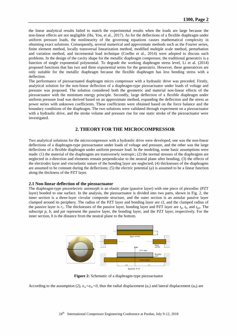
2.1 Non-linear deflection of the piezoactuator The diaphragm-type piezoelectric unimorph is an elastic plate (passive layer) with one piece of piezodisc (PZT
layer) bonded to one surface. In the analysis, the piezoactuator is divided into two parts, shown in Fig. 2, the
inner section is a three-layer circular composite structure, and the outer section is an annular passive layer
clamped around its periphery. The radius of the PZT layer and bonding layer are r2, and the clamped radius of
the passive layer is r1. The thicknesses of the passive layer, bonding layer and PZT layer are tp, tb, and tpzt. The
subscript p, b, and pzt represent the passive layer, the bonding layer, and the PZT layer, respectively. For the
inner section, h is the distance from the neutral plane to the bottom.
Figure 2: Schematic of a diaphragm-type piezoactuator
According to the assumption (2), erz=eθz=0, thus the radial displacement (ur) and lateral displacement (uθ) are

1300, Page 3
24th International Compressor Engineering Conference at Purdue, July 9-12, 2018
( , )0
( , )0
rw r u
r z
w r u
r z
(1)
where w(r,θ) represents the transverse displacement.
The geometrical non-linear strain-displacement relations are given by
21
2
rr
r
du dwe
dr dr
ue
r
(2)
where er and eθ are the radial and the lateral strains.
According to the Hook’s Law, normal stresses in radial (σr,p) and lateral (σθ,p) directions of the passive layer are
22
, 2 2 2
22
, 2 2 2
1
1 1 2
1
1 1 2
p p p
r p r p
p p
p p
p p r p p
p p
E E vd w dw dwe v e z z
v v dr r dr dr
E E d w dw dwe v e zv z v
v v dr rdr dr
(3)
where Ep and vp are the Young’s modulus and Poisson’s ratio.
Similarly for the bonding layer, the normal stresses in radial (σr,b) and lateral (σθ,b) directions can be calculated.
The non-linear effects of electrostrictive and electroelastic in the PZT layer were considered. Combined with the
piezoelectric constitutive equations, the normal stresses of the piezodisc in radial (σr,pzt) and lateral (σθ,pzt)
directions are expressed as
, 11 11
22
11 112
, 11 11
22
11 112
1
2
1
2
r pzt r pzt
pzt
pzt pzt r
pzt pzt
Q e v e M
vd w dw dwQ z z M
dr r dr dr
Q e v e M
d w dw dwQ zv z v M
dr rdr dr
(4)
where 2
11 11 3111 1E
z pztQ s d E v , 2
11 31 11 311 31 11 3111 2 1E E
z z pzt z z pztM d E s d E v m E s d E v , d311 is the
electroelastic compliance coefficient, m31 is the electrostrictive compliance coefficient, s11 is the compliance
constants, and d31 is the piezoelectric constant, Ez is the driven electric field strength in the PZT layer.
From Eqs. (1)-(4), the elastic potential energy of the three layers can be obtained through volume integration.
Firstly, the elastic potential energy of the passive layer is calculated as
, ,
, , , , , , , , , ,
1 1( ) ( )
2 2p inner p outer
p p inner p outer r p r p p p r p r p p p
V V
U U U e e dV e e dV
(5)
where Up,inner and Up,outer represent the elastic energy of the passive layer in the circular inner composite section
and the annular outer section. They are expressed as following,
2
1
2
2
, , , , ,0 0
2 2
, , , , ,0 2
1( )
21
( )2
p
p
p
r t h
p inner r p r p p ph
r t
p outer r p r p p pr t
U e e rdrd dz
U e e rdrd dz
(6)
Likewise, the elastic energy of the bonding layer can be calculated as well. The energy in the PZT layer consists
of two parts: the elastic potential energy and the electric energy. The elastic potential energy is expressed as
22
, , , ,0 0
1( )
2
p b pzt
p b
r t t t h
pzt r pzt r pzt pzt pztt t h
U e e rdrd dz
(7)
The stored electric energy in the PZT layer is calculated as
1
2pzt
T
e z z
V
W D E dV (8)
According to the assumption (6), the electric field strength is given by
0 1
1z
a a z
dE a
dz
(9)
where a0 and a1 are coefficients, and a1=(V1-V2)/tpzt.
As the constant uniform pressure load (P) actuates on the diaphragm-type piezoactuator in positive z-direction,
the actuator is deformed and elastic potential energy is stored in the actuator. This part of energy is equal to the

1300, Page 4
24th International Compressor Engineering Conference at Purdue, July 9-12, 2018
work done by the pressure load acting on the piezoactuator and is given by
1
02
r
g gU W rPwdr (10)
The piezoactuator reaches equilibrium state under the loads of driving voltage (V1-V2) and resisting pressure (P)
when the total energy gets the minimum. The total energy of the piezoactuator is expressed as
p b pzt E gL U U U W W (11)
The deflection function of the piezoactuator is assumed as a function of power series, which satisfy the clamped
boundary condition. The coefficients in the series are taken when the total energy reaches the minimum. In order
to satisfy the boundary condition, the function of the power series is expressed as
2 12 2
2 211 1
12 2
1 ( 1)
( ) 1 1 ( )
1( )
( 1)!
in
i
i
n
n
r rw r C R n
r r
r rR n w
n
(12)
where R(n) is the remainder term of the series and the Ci (i=1,2,3,…,n) are the coefficients to minimize the total
energy (L). These coefficients are calculated through below equations,
0, ( 1,2,3,..., )i
Li n
C
(13)
The non-linear static deflections of the circular edge-clamped diaphragm-type piezoactuator are obtained once
the above unknown coefficients are settled. Moreover, the w(r) is investigated with the increase of degrees (n),
and the deflections are stable when n≥3, thus we take n=4 in the solution.
2.2 Large deflections of the flexible diaphragm Deflection of a flexible diaphragm under uniform pressure load is schematically presented in Fig. 3. The radius
and thickness of the diaphragm is R and hf. Unlike the metallic diaphragm, the flexible diaphragm only has the
stretching strain or stress when it deformed under uniform pressure load. The force equilibrium equations in the
two directions are expressed as (Zhang & Wang, 2011),
( )
2
( )
r
r
d prN w
drd dw
N rN prdr dr
(14)
where Nr and Nθ represent radial and later stress resultant of the flexible diaphragm, w is the diaphragm
deflection and P is the uniform pressure load.
Figure 3: Large deflection of a flexible diaphragm under uniform pressure load
Relationship between the stress and strain in the radius and lateral directions is,
r f r
r f
N vN Eh e
N vN Eh e
(15)
where er and eθ are radial and lateral strain of the diaphragm.
Nonlinearity of the Equation (15) causes mathematical complexity in acquiring exact solutions of the deflection
and stress. Therefore, an approximate method was adopted to solve the equations. In the solution, the deflection
(w) and stress resultant (N) were expanded to power series with unknown coefficients. These coefficients were
solved through boundary conditions and equations that obtained from Equation (15).
Non-dimensional parameters were introduced for the convenience: W=w/R, N=Nr/(Ehf), ρ=r/R and q=PR/(Ehf).
Thus, the Equation (15) can be rewritten as,
2 22 2 2 3 2
2
1 13 0
2 81
2
d N dNN N N
dr d qdW
N qd
(16)
To satisfy the boundary conditions, the W and N were expanded as,

1300, Page 5
24th International Compressor Engineering Conference at Purdue, July 9-12, 2018
2
2
0
2 2
2
0
1
n
n
n
n
N n
W m
(17)
Substitute Equation (23) into the Equation (21), the unknown coefficients can be expressed as the function of n0
through equaling the coefficients in the same exponent terms.
The boundary condition can be rewritten as the non-dimensional form,
1
0d dW
N vNd d
(18)
Combined with the Equation (23), the relationship between the unknown coefficients is
0 2 4 0 2 4 6
1 3 52 3 4 0
2 2 2n n n w w w w
(19)
The deflections and stresses of the circular flexible diaphragm are obtained after the unknown coefficients are
solved, and we take n=10 in the solution.
3. PIEZOACTUATOR WITH A HYDRAULIC DRIVE
Based on above solutions, the deflections of the piezoactuator and the flexible diaphragm in the new actuator
with a hydraulic drive can be calculated since the piezoactuator and the flexible diaphragm generate same stroke
volume. To validate the accuracy of the proposed solutions, two actuators with a hydraulic drive were fabricated.
One was the structure that the radius ratio of the piezoactuator and flexible diaphragm (r1/r3) was 1, and the
other was r1/r3=1.94, shown in Fig. 4. In the two actuators, the piezoactuator is a laminated composite. The
clamped radius of the piezoactuator is 15.5 mm. The flexible diaphragm in the actuators is PDMS with a
thickness (hf) of 0.1 mm. The 46# hydraulic oil was employed in the new actuator.
(a) (b)
Figure 4: Photograph of the two actuators with a hydraulic drive: (a) r1/r3=1, (b) r1/r3=1.94
Deflections of the piezoactuator and the PDMS were both tested. The schematic of the test rig for the
deflections of the actuators is shown in Fig. 5. There are the tested actuators, a signal generator, and a signal
amplifier, an oscilloscope to display the signal, and a laser displacement sensor (resolution: 0.1 μm) to measure
the transverse displacement.
Figure 5: Schematic of the experimental setups

1300, Page 6
24th International Compressor Engineering Conference at Purdue, July 9-12, 2018
The piezoactuator was driven by a 2 Hz square wave signal, which is far less than its 1st resonant frequency
measured around 1.4 kHz, and the voltage amplitude varied from 10 V to 90 V in steps of 5 V. For each driven
voltage, deflections of the piezoactuator and PDMS were measured, and compared with the analytical results.
Center displacements of the piezoactuator, the PDMS membrane with different radius are shown in Fig. 6, the
piezoactuator nonlinearly increases with the driving voltage because of the geometric and material nonlinear
effects, and results from the analytical solution match well with the results from the experiments. The maximal
offset is less than 6%. Moreover, the center displacements of the PDMS from analytical solution also agree well
with the results from experiments. They also nonlinearly increase with the rise of the voltage. For the case of
r3=15.5 mm, the center displacement of the flexible diaphragm is slightly lower than the displacement of the
piezoactuator under the same voltage load. This is mainly because their different stress conditions leads to a
different deflection. As for the case of r3=8 mm, under the voltage of 80 V, the center displacement of the
piezoactuator is 35.6 μm, while the center displacement of the PDMS is 110.9 μm, which is nearly 3.1 times of
the piezoactuator. In that case, deflection of the PDMS is significantly amplified due to the piezoactuator and the
PDMS generate same stroke volume in the deformation. In addition, the profiles of the piezoactuator and the
PDMS with different radius under various voltage loads were measured as well, shown in Fig. 7. From the
figure, the profiles of the piezoactuators and the PDMS from analytical solutions match the experimental results
as well. Therefore, the proposed analytical solutions are accurate enough in predicting the deflections of the
piezoactuator and flexible diaphragm. Based on the analytical solutions, performance of the micro compressor
was further studied in the next section.
Figure 6: Center displacements of the piezoactuator and the PDMS under various voltage loads
(a) (b) (c)
Figure 7: Deflection profiles of the (a) piezoactuator and PDMS with radius of (b) 15.5 mm and (c) 8 mm
4. PERFORMANCE OF THE MICROCOMPRESSOR
Working processes of the piezoelectric micro compressor with a hydraulic drive are represented in Fig. 8. In the
figure, (a) is the initial state of the actuators. As a driving voltage is imposed on the piezodisc, the piezoactuator
positively deformed to push the flexible diaphragm compress the gas in the chamber until the diaphragm reaches
the state of (b), which is the end of the gas compression. Then, the discharge valve opens to discharge the
compressed gas, and the flexible diaphragm totally clings to the cavity surface at the end of the gas discharge, as
state (c). The piezoactuator restores to the initial state and pullback the flexible diaphragm to suction new gases
to the chamber. To modeling the micro compressor, three assumptions are made: (i) compressed gas in the
chamber is thought as the ideal gas at constant temperature; (ii) loss from the gas flow and valves are

1300, Page 7
24th International Compressor Engineering Conference at Purdue, July 9-12, 2018
disregarded; (iii) gas pressure outside the chamber remains constant as P0.
Figure 8: Compression process of the proposed micro diaphragm compressor, (a) the initial state, (b) end of the
gas compression, (c) end of the gas discharge
The cavity profile of a diaphragm compressor plays a significant role in determining the flowrate and the
diaphragm operating life span. The generatrix of the cavity was designed based on an optimization method that
elaborated in our previous published paper (Hu, Xu, et al., 2017).The designed generatrices and the radial stress
of the PDMS diaphragm for the three cavity volumes of 10, 15 and 20 μL are presented in Fig. 9.
(a) (b)
Figure.9: (a) The cavity generatrix and (b) the radial stress of the PDMS for different cavity volume
Based on the cavity shape of the micro compressor, the gas compression work done by the flexible diaphragm
from the initial state to the end of the gas compression state is
0
0 0 0 0 0 0 0( ) ln( ) ( )V
gV
W PdV P V V PV V V P V V (20)
The chamber volume (V) during compression is,
1
02 ( ( ))
r
V r w g r dr (21)
Combined with the analytical solutions of the piezoactuator and the flexible diaphragm, performance of the
micro compressor with a hydraulic drive can be predicted. According to the structure of the hydraulic drive,
deflection of the flexible diaphragm can be adjusted by the radius ratio of the piezoactuator and the flexible
diaphragm (r1/r3). Under the same cavity volume, a higher radius ratio results in a larger flexible diaphragm
deflection and a deeper cavity depth, but it also leads to a higher radial stress of the diaphragm. Effects of the
radius ratio (r1/r3) on the cavity depth and the maximal radial stress of the PDMS diaphragm are presented in
Fig. 10. From the figure, the depth of the cavity and the maximal radius stress of the PDMS increase with the
rise of the radius ratio. The ascending slope of the cavity depth is higher than that of the maximal radial stress
when the radius ratio is less than 2, but the slope of the maximal radial stress becomes higher when the radius
ratio is over 2.5. With the radius ratio changed from 1.55 to 2.2, the depth of the cavity increases by 1.8 times,
while the maximal radial stress of the PDMS increases by 7 times. Therefore, radius ratio of the piezoactuator
and the flexible diaphragm should be lower than 2.2 to avoid high stress of the flexible diaphragm.

1300, Page 8
24th International Compressor Engineering Conference at Purdue, July 9-12, 2018
Figure 10: Cavity depth and maximal radial stress of the PDMS vs. radius ratio (r1/r3)
The pressure rise and stroke volume are further discussed for one static stroke of the piezoactuator. In the
discussion, radius of the piezoactuator is 15.5 mm, the cavity volume is 10 μL, and the radius ratio of the
piezoactuator and PDMS diaphragm (r1/r3) is 1.94. The initial pressure (P0) was kept constant at 101.3 kPa.
Since there is an electric field applicability limit for the PZT ceramic (Malysh & Erhart, 2005), the imposed
voltage is controlled below 100 V in the discussion. The pressure rise and stroke volume of the micro
compressor under various driving voltages are represented in Fig. 11. From the figure, the flexible diaphragm
could cling to the cavity surface only when the driving voltage is over 80 V, that is, the deflections of the
flexible diaphragm is inadequate to ensure it contact with the cavity surface at the end of gas discharge when the
driving voltage is lower than 80 V. As the driving voltage at 80 V, the diaphragm could cling to the cavity
surface when the pressure rise is lower than 3 kPa, and the maximal pressure rise is 16.5 kPa. As the driving
voltage at 100 V, the actuation force was significantly improved. The diaphragm can cling to the cavity surface
when the pressure rise is lower than 24 kPa, and the micro compressor has the best performance at this working
condition. The maximal pressure ratio of the micro compressor with a hydraulic drive is 1.46 at the driving
voltage of 100 V.
Figure 11: Pressure rise vs. flow rate of the diaphragm compressor with a cavity volume of 10 μL
5. CONCLUSION
A piezoelectric micro compressor with a hydraulic drive is proposed to improve its volumetric efficiency and
actuation force. Two solutions concerning with the micro compressor are developed. The solutions are validated
to be accurate through experimental measurements. Based on the proposed solutions, effects of the radius ratio
(r1/r3) on the cavity depth and the maximal radial stress of the diaphragm are firstly investigated. The results
indicate that radius ratio (r1/r3) should be lower than 2.2 to avoid high stress of the flexible diaphragm.
Furthermore, the pressure rise and stroke volume of the micro compressor are investigated under conditions of
r1/r3=1.94, Vc=10 μL and P0=101.3 kPa. The results show that the flexible diaphragm can cling to the cavity

1300, Page 9
24th International Compressor Engineering Conference at Purdue, July 9-12, 2018
surface only when the driving voltage is over 80 V. As the voltage is 100 V, the diaphragm can cling to the
cavity surface when the pressure rise is lower than 24 kPa, and the maximum pressure ratio is 1.46.
Acknowledgments The authors are grateful for the support of the National Science Foundation of China
(Grant No. 51576123).
NOMENCLATURE
D electric displacement (C/m2)
E Young’s Modulus (Pa)
N Stress resultant (N)
U energy (W)
e strain
h thickness (m)
w transverse displacement (m)
p pressure (Pa)
σ stress (Pa)
ν Poisson’s ratio
Subscript
b bonding layer
g gas
p passive layer
pzt PZT layer
r radial direction
θ lateral direction
REFERENCES
Coelho, M., Roehl, D., & Bletzinger, K.-U. (2014). Numerical and analytical solutions with finite strains for
circular inflated membranes considering pressure–volume coupling. International Journal of Mechanical
Sciences, 82, 122-130.
Deshpande, M., & Saggere, L. (2007). An analytical model and working equations for static deflections of a
circular multi-layered diaphragm-type piezoelectric actuator. Sensors and Actuators A: Physical, 136(2),
673-689.
Hu, Y., Xu, X., & Wang, W. (2017). A new cavity profile for a diaphragm compressor used in hydrogen fueling
stations. International Journal of Hydrogen Energy, 42(38), 24458-24469.
Hu, Y., You, H., & Wang, W. (2017). Non-linear deflection of a circular diaphragm-type piezoactuator under
loads of voltage and pressure. Sensors and Actuators A: Physical, 268, 91-100.
Laser, D. J., & Santiago, J. G. (2004). A review of micropumps. Journal of Micromechanics and
Microengineering, 14(6), 35-64.
Le, S., & Hegab, H. (2017). Investigation of a multistage micro gas compressor cascaded in series for increase
pressure rise. Sensors and Actuators A: Physical, 256, 66-76.
Li, J., Jia, X., Wu, Z., & Peng, X. (2014). The cavity profile of a diaphragm compressor for a hydrogen refueling
station. International Journal of Hydrogen Energy, 39(8), 3926-3935.
Li, S., & Chen, S. (2003). Analytical analysis of a circular PZT actuator for valveless micropumps. Sensors and
Actuators A: Physical, 104(2), 151-161.
Malysh, T., & Erhart, J. (2005). Electric Field Applicability Limits for PZT Ceramics. Ferroelectrics, 319(1),
45-56.
Mathew, B., & Hegab, H. (2013). Lumped model of MEMS diaphragm compressors. Energy Conversion and
Management, 67, 376-384.
Sathe, A. A., Groll, E. A., & Garimella, S. V. (2008). Analytical model for an electrostatically actuated miniature
diaphragm compressor. Journal of Micromechanics and Microengineering, 18(3), 035010.
Yoon, J. S., Choi, J. W., Kim, M. S., Yoo, Y.-E., & Choi, D.-S. (2009). Studies on the performance
characteristics and improvements of the piezoelectrically-driven micro gas compressors. Microelectronic
Engineering, 86(11), 2297-2304.
Zhang, Y., & Wang, W. (2011). Analytical model of electrostatic actuators for micro gas pumps. Microsystem
Technologies, 17(10-11), 1683-1696.