Embed Size (px)
Citation preview

A Patient GuideLiving with your 5-ICD- System
Rx Only
2611 Page

The minimally invasive S-lCD® SystemCopyright © 2012 Cameron Health, Inc., San Clemente, CA, USA.All rights reserved.
Cameron Health, Inc.905 Calle AmanecerSuite 300San Clemente, CA 92673 USATel: 19494985630Free: 1 877 SICD 411
1 877 742 3411Fax: 1 949 498 5932
Cameron Health BVWorld Trade CenterNieuwe Stationsstraat 106811 KS, ArnhemThe NetherlandsTel: +31263550260Free: +800 SICD 4 YOU
+800 7423 4 968Fax: +31 26 3550269
www.cameronhealth.com
Limited Software License and Equipment Use*S-ICD®, SQ-RX® and Q-TRAK® are all registered trademarks of Cameron Health, Inc. Q-GUIDEM and Q-TECH"
are all trademarks of Cameron Health, Inc.Manuals or other written documentation may not be copied or distributed without Cameron Health, Inc. 2 7authorization.
21 Page

TABLE OF CONTENTS
About This Guide 4
GLOSSARY OF TERMS 5
INTRODUCTION TO THE S-ICD SYSTEM 8
UNDERSTANDING YOUR HEART 9
The Normal Heart 9
When the Heart Beats Too Fast 9
Ventricular Tachycardia 10
Ventricular Fibrillation 10
Why do I need a minimally invasive S-ICD System? 10
Am I at risk for developing a Ventricular Tachycardia or Ventricular Fibrillation? 10
WHAT IS THE MINIMALLY INVASIVE S-ICD SYSTEM? 11
S-ICD System Components Pulse Generator 11
Subcutaneous Electrode 11
Benefits and Risks of Having an S-ICD System 12
UNDERSTANDING THE IMPLANT PROCEDURE 13
Discharge from the Hospital 13
Pulse Generator Replacement 13
LIVING WITH YOUR S-ICD SYSTEM 14
Patient Responsibilities 14
ENVIRONMENTAL SAFETY WARNINGS AND PRECAUTIONS 16
Electromagnetic Interference (EMI) 16
Household Appliances and Common Tools 16
Environmental Safety Warnings and Precautions 17
Warnings 17
Environmental Safety Precautions 17
Medical Procedures 18
Cellular phones 19
Anti-Theft Security Systems 19
Airport Security 19
FREQUENTLY ASKED QUESTIONS 20
INDEX 22
NOTES 23
31 Page

ABOUT THIS GUIDE
This patient guide provides information on:* Glossary of terms* Anatomy of the heart* Heart rhythm* The S-/CD System* Implant procedure* Post operative events
Note: Your physician will discuss any potential risks or adverse events that may be associatedwith your implanted S-lCD System. However, be sure to carefully read and understand allwarnings and safety precautions discussed in this guide.
29
4IPage

GLOSSARY OF TERMS
ArrhythmiaAn abnormal heartbeat that is too fast, too slow, or irregular.
Atrium (plural: atria)One of the two upper chambers of the heart specifically, the right atrium and left atrium. The atria collectblood as it comes into the heart and pump blood into the lower chambers (ventricles).
BradycardiaAn abnormally slow heartbeat, typically fewer than 60 beats per minute.
Cardiac arrestSee sudden cardiac arrest (SCA).
DefibrillationProcedure in which a fast heart rate (i.e., ventricular fibrillation) is restored to a normal rhythm by deliveringan electrical shock.
DefibrillatorA device that delivers an electrical shock to the heart to restore an extremely rapid and irregular heart rate to
a normal rhythm. A defibrillator may be an implanted medical device or external medical equipment.
DeviceSee pulse generator.
Ejection fractionThe percentage of blood ejected from the left ventricle with each heartbeat. A healthy ejection fraction is
usually higher than 55%, although this can vary depending on the individual. Patients with a low ejection
fraction may have an increased risk of sudden cardiac arrest.
ElectrodeAn insulated wire that is implanted under the skin and connected to the device. The electrode senses yourheartbeat and delivers pacing pulses and/or shocks from the device to the heart.
Electromagnetic fieldInvisible lines of force that result from electrical fields (produced by voltage) and magnetic fields (produced
by current flow). Electromagnetic fields decrease in strength the farther they are from their source.
Electromagnetic interference (EMI)Interference that occurs when an implanted device interacts with an electromagnetic field. See also
electromagnetic field.
FibrillationSee ventricular fibrillation.
Heart attackSee myocardial inforction (MI).
Heart rhythmA series of heartbeats. You may hear your physician refer to your rhythm as being normal or irregular. A
normal heart rate typically ranges from 60 to 100 beats per minute at rest.
Implantable Cardioverter Defibrillator (ICD) systemA device (also called a pulse generator) and leads. An ICD system is implanted to monitor your heart rhythm
and help treat dangerously fast or slow arrhythmias.30
5|1P ag e

Myocardial infarction (MI)Also called a heart attack. A myocardial infarction occurs when an artery that supplies blood to the heartbecomes blocked. As a result, blood does not reach some parts of the heart, and some of the heart tissuedies. Symptoms of a myocardial infarction may include pain in the chest, arm, or neck; nausea; fatigue;and/or shortness of breath.
ProgrammerMicrocomputer-based equipment used to communicate with the device. The programmer is used duringtesting and follow-up exams to gather and display information from the device. The physician or technicianalso uses the programmer to adjust the device so that it senses and treats your arrhythmias.
Pulse generatorAlso called a device. The pulse generator is the part of the ICD system that contains the electronics and thebattery; it is implanted under the skin on the left side of the chest.
Radio frequency (RF) wireless communicationTechnology that allows the device to exchange information with a programmer by communicating over radiosignals.
Sinoatrial (SA) nodeThe heart's natural pacemaker. The SA node is a small group of specialized cells in the upper right chamberof the heart (right atrium) that normally generates an electrical signal. This signal runs through the heart andcauses the heart to beat.
Sternum(Breast Bone) Bone located in the center of the chest which connects the ribs.
SubcutaneousJust beneath the skin.
Sudden cardiac arrest (SCA)The sudden, abrupt loss of heart function usually due to electrical problems in the heart that cause adangerously fast and irregular heart rhythm. If untreated, SCA can lead to death (also called sudden cardiacdeath).
Sudden cardiac death (SCD)Death occurring from sudden cardiac arrest. See also sudden cardiac arrest (SCA).
Wireless communicationTechnology that allows a device to exchange information with a programmer wirelessly. See also radiofrequency (RF) wireless communication.
VentricleOne of two lower chambers of the heart. The right ventricle pumps blood to the lungs, and the left ventriclepumps oxygen-carrying blood from the lungs to the rest of the body.
Ventricular fibrillation (VF)A very fast, irregular heart rhythm caused by abnormal electrical signals starting from several areas of theventricle. In VF, the ventricle beats so fast that it pumps very little blood to the body. A heart in VF may beatmore than 300 beats per minute. Without immediate medical attention, VF can be fatal. Defibrillation is theonly way to treat VF once it occurs.
6I Page

Ventricular tachycardia (VT)A fast rhythm caused by abnormal electrical signals coming from the ventricle. The rapid rate of 120 to 250beats per minute may produce dizziness, weakness and eventual unconsciousness. VT may progress toventricular fibrillation.
71 Page

INTRODUCTION TO THE S-ICD SYSTEM
INTRODUCTION TO THE S-ICD SYSTEMYour physician has recommended a Cameron Health minimally invasive implantable defibrillator (S-ICDSystem). The S-ICD System is designed as a life saving measure to treat your heart rhythm abnormalities.
Your physician may have prescribed this device for you for one of the following reasons:
* You have experienced an abnormally rapid heart rhythm (Ventricular Tachycardia or VentricularFibrillation)
* You are at risk of developing an abnormally rapid heart rhythm.
These rapid heart rhythms, known as cardiac arrhythmias, may be life threatening. When a cardiacarrhythmia occurs, it interrupts the normal pumping function of the heart. This disruption of normal heartfunction may lead to loss of consciousness, and ultimately, be lethal.
The minimally invasive S-ICD System is a treatment for correcting an abnormally rapid heart rhythm. The 5-ICD System is not a cure for the underlying cause of your cardiac arrhythmia, but rather serves as anautomatic "emergency response team" in your chest.
8I Page

UNDERSTANDING YOUR HEART
UNDERSTANDING YOUR HEARTThis section will discuss the basic function of the normal heart and will also explain what happens when theheart develops abnormally rapid heart rhythms.
The Normal HeartThe heart is divided into four chambers: two upper chambers called the atria and two lower chambers calledthe ventricles (Figure 1). The four chambers fill with blood when the heart is at rest and then pump the bloodthroughout the body with each heart contraction.
Left
RightAtrium
Left VentricleRight Ventricle
Figure 1: Chambers of the Heart
The heart has a specialized conduction system that produces electrical impulses that stimulate the heart tocontract. Normally, your heart's pumping action is controlled by steady electrical signals that are producedby your heart's natural pacemaker, the sinoatrial (SA) node. Electrical signals from the SA node travelthrough the atria and follow an electrical pathway to the ventricle. This creates an electrical stimulation thatcauses the heart muscle to contract. The heart then rests and fills with blood until the next contractionoccurs. This cycle occurs millions of times in a year.
Normal resting heart rates are usually in the range of 60 to 100 beats per minute. However, your heart ratemay increase or decrease outside this range depending on activity levels. Generally, the heart rate willincrease during exercise and decrease during sleep.
91Page

When the Heart Beats Too FastAn abnormal condition exists when your heart rate increases significantly in the absence of exercise oremotional stress. This is known as a tachycardia. Not all tachycardias cause serious problems. Sometachycardias may cause discomfort, but are not life threatening; whereas other tachycardias may be veryserious and life threatening.
Tachycardias are also associated with injury to the heart muscle, which can occur with coronary arterydisease. Coronary artery disease may cause a myocardial infarction (commonly referred to as a heart attack),which may damage the heart muscle. Tachycardias may also result from other diseases or certain geneticdefects that weaken the heart muscle.
If this rapid heartbeat continues, you may feel skipped beats or dizziness. You could eventually becomeunconscious, and your heart might stop beating (cardiac arrest).
Ventricular TachycardiaA tachycardia that originates in the lower chamber of the heart, or ventricle, is known as VentricularTachycardia (VT). When ventricular tachycardia is very fast, unstable and irregular, it may becomeventricular fibrillation.
Ventricular FibrillationVentricular Fibrillation (VF) causes the heart to quiver which prevents the heart from pumping blood to yourbody. If you are experiencing VF, you may become unconscious within a few seconds. Death is almostcertain unless an electrical shock is delivered to the heart to restore the heart back to a normal rhythm.
Why do I need a minimally invasive S-lCD System?Your physician has recommended implantation of a minimally invasive S-ICD System because you are at riskfor VT or VF. Some heart disorders that are associated with risks of developing VT or VF are listed below:
* Heart Attack: Occurs when there is a complete or sudden loss of oxygen-rich blood flow to theheart muscle due to a blocked or narrowed coronary artery. Due to the lack of an oxygen-richblood supply, a portion of the heart muscle is injured.
* Heart Failure: A condition in which the heart cannot pump enough blood to the body or otherorgans.
* Cardiomyopathy: A disease process that causes the heart to become abnormally large,thickened or stiffened. As a result, the heart muscle weakens, decreasing the heart's ability topump blood efficiently to the body.
* Primary Rhythm Disorder: An abnormality within the conduction system in the heart.
Am I at risk for developing a Ventricular Tachycardia or Ventricular Fibrillation?When a portion of the heart muscle is injured or the heart is abnormally enlarged, the heart is not able topump blood efficiently to the body. Measurements may be made to assess the condition of your heart. Onesuch measurement is known as ejection fraction (EF). EF measures how much blood is pumped out to thebody with each heart beat, or contraction.
Medical studies have determined that patients who have a low EF measurement are particularly at risk fordeveloping ventricular tachycardias or ventricular fibrillation.
-45
10 1p a ge

WHAT IS THE MINIMALLY INVASIVE S-ICD SYSTEM?
WHAT IS THE MINIMALLY INVASIVE S-ICD SYSTEM?The implantable components of the minimally invasive S-lCD System are implanted beneath the surface ofthe skin outside the rib cage.
S-lCD System Components Pulse Generator
Figure 2: Pulse Generator
The pulse generator (Figure 2) is a battery powered, computer controlled device encased in metal. The pulsegenerator is implanted on the left side of the chest wall.
Various settings and parameters for the pulse generator are programmable through wireless communicationwith an external programmer. Your physician can program various settings in your pulse generator toaccommodate your particular cardiac condition. When the pulse generator detects an abnormally rapidheart rhythm, a shock is delivered to restore the heart back to its normal rhythm. This shock therapy is calleddefibrillation. The S-ICD System will record and store these abnormally rapid heart rhythms. Your physicianmay retrieve the saved information during your routine scheduled follow-up visits. This can be accomplishedvia a wireless external programmer called the Q-TECH Programmer.
Subcutaneous ElectrodeThe subcutaneous electrode comprises a partially coated (insulated) wire that is surgically implanted aboveand to the left of the breastbone (sternum). The subcutaneous electrode is connected to the pulse generator(Figure 3).
The S-ICD System uses the electrode to sense electrical signals in the heart. When necessary, the S-ICDSystem delivers a shock to restore the heart back to normal rhythm.
36111 P a g e

The pulse generator and electrode materials that come in contact with the body have been tested for bio-compatibility. The pulse generator and electrode are composed of titanium and other metals. Allergicreactions are uncommon, but you should discuss any known allergies to metals with your physicians.
Electrode left of Breastbone Pulse Generator Connection- Left Side of rib cage
Figure 3: Subcutaneous Electrode Placement
Benefits and Risks of Having an S-lCD SystemYour physician has decided that you should receive an implantable defibrillator (ICD) because you have anincreased risk of sudden cardiac death due to ventricular rhythm disturbances. In particular, your physicianbelieves you may benefit from the S-ICD System. The S-ICD System avoids some complications associatedwith transvenous leads by providing therapy without a lead(s) placed inside your heart. Additionally, the S-ICD System does not require the use of x-ray radiation during the implant procedure.
As with all ICD systems, there are risks associated with the 5-ICD System. Although infrequent, some of therisks that may be encountered during the implant procedure include the following:
* Formation of a blood clot* Damage to adjacent structures (tendons, muscles, nerves)* Dangerous arrhythmias* Heart attack* Stroke* Death
After the system is implanted, other infrequent risks may occur, including:* Infection* Erosion of the skin near your device* Electrode and device may move out of place* Delivery of a shock or pacing therapy when it is not needed (inappropriate therapy)* Inability to detect or appropriately treat your heart rhythms due to electromagnetic interference
or malfunction* Difficulty coping with having an implanted device
Be sure to talk with your physician so that you thoroughly understand all of the risks and benefits associatedwith the implantation of this system.
3712 P a ge

UNDERSTANDING THE IMPLANT PROCEDURE
UNDERSTANDING THE IMPLANT PROCEDUREDepending on the hospital and physician practice, local or general anesthesia is administered to make youcomfortable during the implant procedure. The duration of the implant procedure will vary depending onthe type of anesthesia. Because of the lateral location of the pulse generator, females may have to considerundergarments and clothing that do not cause discomfort in the vicinity of the pulse generator pocket.
The following section outlines the basic steps of the implant procedure (Figure 4):1. An incision is made on the left side of the chest, next to the rib cage.2. A pocket, or pouch, is formed under the skin for the placement of the pulse generator.3. Two small incisions are made to the left of the breastbone allowing placement of the
subcutaneous electrode under the skin.4. The subcutaneous electrode is connected to the pulse generator.5. Your physician will then test your ICD system. During this test, your physician will start an
arrhythmia in your heart. The device will recognize the rhythm and give a shock therapy. Duringthis testing you will be sedated to minimize any discomfort.
6. Testing and adjustments are accomplished by the Q-TECH Programmer.7. Once the incisions are closed, the procedure is complete.
Discharge from the HospitalRecovery from your S-ICD System implant procedure should not prevent you from returning to an activelifestyle. Follow your physician's post-operative instructions.
Pulse Generator ReplacementWhen the battery supply of your pulse generator becomes low or depleted, the pulse generator will need tobe replaced. An incision is made along the previous scar and the old pulse generator is exchanged for a newone.
Figure 4: Implant Procedure
3813 1 P a g e

LIVING WITH YOUR S-lCD SYSTEM
LIVING WITH YOUR S-ICD SYSTEMPatient ResponsibilitiesThis section provides an outline of what you should know about your S-lCD System and returning to yourdaily activities post-surgery.
A Patient Identity card (ID) (Figure 5) will be issued to you prior to your discharge from thehospital. Carry this ID card with you at all times. The card will alert medical and securitypersonnel that you have an implanted medical device.Notify your physician if the card is lost.
Note: Always show your ID card when visiting a new physician or dentist, or when passingthrough airport security.
Figure 5: Patient Identity Card
* If you receive a shock while conscious, it may be uncomfortable and startling. Try to remaincalm.
* Receiving a shock at some point in time is an expected event. Be secure in knowing that the S-ICD System has done its job. Follow the instructions that your physician has given you. Be sureto notify your physician whenever a shock occurs. To help your physician, note the followingdetails:* What were you doing when you received the shock?* What was the date and time when you received the shock?* How did you feel before and after receiving the shock? For example, were you dizzy or short
of breath?
To ensure that your S-lCD System continues to function properly, maintain the follow-up visit schedule that isprescribed by your physician. Check with your physician to determine the frequency of these visits.
7914 1 P a g e

It is important to follow your physician's instructions as well as these recommendations:
* Your physician will arrange a follow-up plan with you to check your device and overall health ona regular basis. It is important that you attend your scheduled in-office follow-up visits to assurethat the S-ICD System is working properly, so that the battery can be checked and that theprogrammed settings are appropriate.
* Ask your physician if you have any questions about or notice anything unusual with your device.* Take the medications prescribed for you as instructed by your physician.* Carry your medication list with you at all times.
As a safety feature, the S-ICD System has a built-in self-monitoring function that checks the circuitry of thepulse generator. If you should hear beeping tones coming from your pulse generator, contact your physician.The beeping indicates that your S-ICD System requires immediate follow-up by your physician. Yourphysician or nurse can demonstrate these beeping tones so you will recognize them. Even though the systemhas this warning system, you should always follow your physician's instructions for regular follow-up visits.
You may have difficulty coping with having an implanted device. Some patients find it helpful to contact orjoin a local ICD support group. Your physician or nurse can help you locate one in your area. You can alsosearch for ICD support groups on the internet for more information.
4015 1 P a ge

ENVIRONMENTAL SAFETY WARNINGS AND PRECAUTIONS
Electromagnetic Interference (EMI)
An electromagnetic field is created when using electrical and magnetic devices. Most of the electrical andmagnetic devices you encounter create weak electromagnetic fields. Your S-ICD System is designed toprotect itself from these electromagnetic fields and proper operation of your S-ICD System will not beaffected when you are around the electrical and magnetic devices that create such fields.
Some electrical and magnetic devices, however, emit strong electromagnetic or radio frequency fields, whichcan temporarily affect the function of the S-ICD System. This form of interference is called electromagneticinterference (EMI). Typically, normal S-ICD System function resumes when you move away from theelectrical and magnetic devices creating the EMI. It is important for you to be aware of what electrical andmagnetic devices are likely to interfere with your S-ICD System's normal function. The following paragraphshelp you identify the EMI safety of particular appliances, tools and activities.
Household Appliances and Common ToolsThe S-ICD System allows you to safely operate most household appliances, office equipment and commontools that are properly grounded and in good repair. Use the following guidelines for safe interaction withmany common tools, appliances, and activities.
Items that are safe under normal use:* Air purifiers* Blenders* CD/DVD players* Clothes washing machines and dryers* Electric blankets* Electric can openers* Electric invisible fences* Electric toothbrushes* Fax/copy machines* Hair dryers* Heating pads* Hot tubs/whirlpool baths
NOTE: Consult with your doctor before using a hot tub. Your medical condition may not permitthis activity; however, it will not harm your device.
* Laser tag games* Microwave ovens* Ovens (electric, convection, and gas)* Pagers 4 1
16 1 P a F e

* Patient alert devices* Personal computers* Personal digital assistants (PDAs)
NOTE: PDAs that also function as cell phones should be kept at least 6 inches (15 cm) away fromyour device. Refer to section Cellular Phones.
* Portable space heaters* Radios (AM and FM)* Remote controls (TV, garage door, stereo, camera/video equipment)* Stoves (electric or gas)* Televisions* TV or radio towers (safe outside of restricted areas)* Tanning beds* Vacuum cleaners* VCRs* Video games
ENVIRONMENTAL WARNINGS AND PRECAUTIONSREAD AND FOLLOW ALL WARNINGS AND PRECAUTIONS DISCUSSED IN THIS SECTION. FAILURE TO HEED THEWARNINGS AND PRECAUTIONS MAY RESULT IN INAPPROPRIATE SHOCK THERAPY OR FAILURE TO DELIVERSHOCK THERAPY. AS A GENERAL RULE, IF YOU ARE OPERATING ANY ELECTRICAL OR BATTERY POWEREDEQUIPMENT AND YOU RECEIVE A SHOCK, YOU SHOULD STOP OPERATING THE EQUIPMENT. IN ADDITION, IFYOUR DEVICE STARTS BEEPING, YOU MAY BE IN THE PRESENCE OF A STRONG MAGNETIC FIELD AND YOUSHOULD MOVE AWAY FROM THE POTENTIAL MAGNETIC SOURCE UNTIL YOUR DEVICE STOPS BEEPING.TEMPORARY BEEPING MAY ALSO BE AN INDICATION THAT YOUR DEVICE HAS DETECTED A MALFUNCTION. IFYOU HEAR YOUR DEVICE BEEPING, CONTACT YOUR PHYSICIAN IMMEDIATELY. TALK TO YOUR PHYSICIAN IFYOU HAVE ANY QUESTIONS OR CONCERNS REGARDING THIS INFORMATION.
WarningsCertain electrical or magnetic fields may interfere with the S-ICD System's function. To minimize thepossibility of any interference, try to avoid:
* Strong magnets such as auto wrecking yards and industry* Industrial power generators* Large TV/Radio transmitting towers* Power plants and high voltage power lines
Environmental Safety PrecautionsThis section presents the environmental safety precautions for which you must be aware. Be sure tocarefully read and understand each of these precautions. If you still have questions or concerns regardingthese precautions, please contact your physician or Cameron Health.
If you use any of the following items, it is important that you keep them the recommended distance awayfrom your device to avoid interaction.
Items that should not be placed directly over your device, but are otherwise safe to use:* Cordless (household) telephones* Electric razors* Hand-held massagers* Portable MP3 and multimedia players (such as iPods®) that do not also function as a cellular
phone. 4 217 1P a g e

NOTE: While portable MP3 players themselves should not interfere with your device, theheadphones or earbuds should be stored at least 6 inches (15 cm) away from your device.
Items that should remain at least 6 inches (15 cm) away from your device, but are otherwise safe to use:* Cellular phones, including PDAs and portable MP3 players with integrated cellular phones
NOTE: For more information about cellular phones, see section on "Cellular phones".* Devices transmitting Bluetooth® or Wi-Fi signals (cellular phones, wireless Internet routers,
headphones and earbuds, etc.)* Magnetic wands used in the game of Bingo
Items that should remain at least 12 inches (30 cm) away from your device, but are otherwise safe to use:* Battery-powered cordless power tools* Chain saws* Corded drills and power tools* Lawn mowers* Leaf blowers* Remote controls with antennas* Shop tools (drills, table saws, etc.)* Slot machines* Snow blowers* Stereo speakers
Items that should remain at least 24 inches (60 cm) away from your device, but are otherwise safe to use:* Magnetic wands used in airport screening, government buildings, security systems in shopping
malls, etc.* Arc and resistance welders* Home power generators* Antennas used to operate a CB, ham radio, or other radio transmitter* Running motors and alternators, especially those found in vehicles
NOTE: Avoid leaning over running motors and alternators of a running vehicle. Alternatorscreate large magnetic fields that can affect your device. However, the distance required to driveor ride in a vehicle is safe.
Items that should not be used:* Body-fat measuring scales (handheld)
Jackhammers* Magnetic mattresses and chairs* Stun guns
If you have questions about the EMI safety of a particular appliance, tool or activity, please call CameronHealth Customer Services at 1 (877) 742-3411.
Medical ProceduresInform your physician, nurse, dentist or dental assistant that you have an implanted S-ICD System before anymedical or dental procedure.
4318 1 P a g e

Some medical or diagnostic procedures that may cause interference with the S-ICD System include:* Diathermy* Lithotripsy* Transcutaneous Electrical Nerve Stimulator (TENS)* Radiation Therapy* Surgical and Dental Procedures* Magnetic Resonance Imaging (MRI)* Electrolysis
Cellular phonesIf you use a cellular phone or a cordless phone, it is best to keep the phone more than 15 centimeters or 6inches from your S-ICD System. It is further recommended that your cellular phone be carried on theopposite side of the implanted S-ICD System. When talking on the cellular phone, hold the cellular phone onthe opposite side of the body away from the implantation site. The cellular phone may affect the therapyfunctions of the S-ICD System. Consult your physician if you have specific questions about the S-ICD Systemand the potential interaction with cellular phones.
Anti-theft Security SystemsTypically, anti-theft and security detection systems have minimal effect on the S-ICD System. However, thereare a few notes to remember when in the presence of these devices:
* Anti-theft systems or Electronic Article Surveillance systems are frequently found at theentrances and exits of stores, banks, libraries, etc. Although unlikely, these systems couldinteract with your S-ICD System. To minimize this interaction, pass through these systems at anormal pace without stopping.
* Do not lean against or linger near these systems. If you suspect interaction between your deviceand a theft detection system could occur, just move away from the system to decrease theinterference.
* Most home security systems will not affect the proper function of your device.
Airport SecurityYour device contains metal parts that may set off airport security metal detector alarms. The securityarchway will not harm your device. Tell security personnel that you have an implanted medical device andshow them your Medical Device Identification card.
Airport security wands could temporarily affect your device if the wand is held over it for a period of time(about 30 seconds). If possible, ask to be hand-searched instead of being searched with a handheld wand. Ifa wand must be used, inform the security personnel that you have an implanted medical device. Tell thesecurity personnel that the search must be done quickly and to not hold the wand over your device.
If you have questions about airport security, call your physician or Cameron Health Customer Service at 1(877) 742-3411.
44
19 1P a g e

FREQUENTLY ASKED QUESTIONS
FREQUENTLY ASKED QUESTIONSHow do I know my device is working properly?Regular follow-up visits are required to assess your S-ICD System. Therefore, it is important to follow yourphysician's instructions regarding regular follow-up visits.
How do I know if increased heart rate will result in a shock, for instance from exercise?Your heart rate will generally increase when you exercise. Your physician can program the S-ICD System todeliver therapy only when your heart exceeds a certain rate. While inappropriate shocks may occur, thereare special features in the S-ICD System that are designing to tell the difference between high rates due tovigorous exercise and those due to an arrhythmia that needs therapy.
Is pacing available in the S-ICD System?Pacing used to treat slow heart rates (Bradycardia) is only available following shock therapy. Following shocktherapy, the heart may slow down or be interrupted for a brief period. The pacing following shock therapy isused for temporary support until your own heart rate returns to normal.
How often does the S-ICD System deliver therapy?Therapy delivery varies for each patient and may be dependent upon your specific heart condition.
How long will the battery last?The battery in the S-ICD System can typically last five years. There are factors that could affect battery lifeincluding your heart condition and the amount of therapy you receive. Your device will regularly check itsown battery. At every follow-up visit, the physician or nurse will also check to see how much energy isremaining in the battery. When the battery's energy level decreases to a certain point, the device will beginto beep and will need to be replaced.
What will it feel like if I receive a shock?Patients vary in their descriptions of experiencing a shock. These descriptions range from a "mild thump" toa "swift kick" in the chest. Most patients are reassured in knowing that a rapid heart rhythm was treatedwith the shock and they can resume their normal daily routine. Follow your physician's instructions if youreceive a shock.
What happens if someone is touching me when I receive a shock?If you receive a shock while engaging in physical contact with another individual, including during sexualintimacy, they may feel a harmless tingling sensation that lasts for an instant.
4520 1 P a g e

Will I be able to engage in sexual intimacy?For most patients, sexual intimacy is not a medical risk. The natural heart rate increase that occurs during sexis the same as the heart rate increase when you exercise. Exercise testing at the hospital will help yourphysician program your device settings so you should not get a shock during sex. If you receive a shockduring sex, your partner may feel a tingling sensation. The shock is not harmful to your partner. Be sure tolet your physician know if you receive a shock during sex so he or she can consider reprogramming yourdevice.
Will I be able to feel the implanted S-ICD System?Most people are aware of the implanted S-ICD System, but become accustomed to it quickly. For somepatients, discomfort or pain near the pulse generator or electrode may last for several weeks. In raresituations, surgical repositioning may be required to resolve discomfort.
What should I do if my device is beeping?Make note of what you were doing then contact your physician.
Can I exercise?The S-ICD System itself does not prevent you from exercising. Follow your physician's instructions on theamount and type of exercise you are permitted to do after implantation of the S-ICD System.
When can I resume driving?Your physician will advise you if, and when, you may drive after your S-ICD System has been implanted. Thisdecision is based upon your specific heart condition. The driving laws for patients who have implantabledefibrillation devices vary from state to state and country to country. Most S-ICD System patients whopreviously drove can resume driving. There are no physical driving impediments attributable to the S-lCDSystem. Furthermore, protection afforded by the S-ICD System helps make driving safe of lethal arrhythmiasymptoms. Receiving a shock during driving is usually uncommon.
Can I travel?The S-ICD System does not prevent you from traveling. Check with your physician about guidelines regardingany travel restrictions. Your physician may give you guidance on whom to speak with or contact whentraveling. If you are traveling overseas, you may also contact Cameron Health Customer Service for thelocation of hospitals that implant and provide follow-up support for the S-ICD System.
Can I use a cellular phone?If you use a cellular phone or a cordless phone, it is best to keep the phone more than 15 centimeters or 6inches from your S-ICD System. It is further recommended that your cellular phone be carried on theopposite side of the implanted S-ICD System. When talking on the cellular phone, hold the cellular phone onthe opposite side of the body away from the implantation site. The cellular phone may affect the therapyfunctions of the S-ICD System. Consult your physician if you have specific questions about the S-ICD Systemand the potential interaction with cellular phones.
4621 P a g e
INDEX M
A M etals .................... . .... ................ 11
A irpo rt Secu rity ................. ... .................. 19 M I .................... S.......................5
A llergic ...................... ................ .11 M yocardial infarction .................... .................... 5,10
A llergies .. ............... . ....................... 11 PAnti-Theft .......19A rrhythm ia ....................... _... ................ 5,9 Pacing Therapy ................. . .. 1................ 13
Atria ..................................... 5,9 Patient Identity Card ... .. 14
A trium ............... ..... . .................... 5,9 Precautio ns ..................... . .................... 17Program m er ..................... :.. .................. 6,11
B Pulse G enerator ................... .. .................. 6, 11
Battery . ............... . . .... ................. 13B e nfits .................. . .... ................ .1 2
Bradycardia ................ . . ................ 5, 20 Q uestions ................. . . .. ................ 20
C R
Cardiac A rrest .................... ... ................. 5 Radio Frequency.................................... 6, 16
Cardiom yopathy ...................... ................. 10 RF ..................................... 6,16
C ellular Pho nes........................................19 risks ................. .................. 12
D S
D efibrillatio n ...................... . . . . . . . .............5. . . ..SA 9Defibrillator5,11 SA Node ................. . .................. .... 6,9
Device 6................. ... ................... . SCA 6,10SC D .................... . . . . ..................... 6, 10
E Secu rity ........................................ 19
EF .................... ................ ..10 Sho ck T herapy .................... .................. 13
Ejection Fraction ....................... .................. 5,10 S-ICD System .................. . ... .. .................... 11
Electro de . ................... .... ................. 5, 11 Sinoatrial no de ..................... ................. 6,9
Electrom agnetic Field ................ 1.6. ... ................. 5, 16 Sternum................... ................... 6, 11
Electrom agnetic Interference...... .......... S..6.....................15, 16 Subcutaneous. .................. ... ................ 6, 13Sudden Cardiac Arrest ................ .. .. ................... 6,10
F Sudden Cardiac Death........................................ 6, 10
Fib rillatio n ................ .. T.. . .................. 5, 11 T
G Tachycardia .................................... 10
G lossary ................. .. v. ... ............... V
H V e ntricle ................. .. .................... 6,9
H eart ................... . . .. ................. 9 V entricu lar Fibrillatio n ....................................... 6,10
Heart attack ................ . .... . ................. 5,9 Ventricular Tachycardia .................... .................. 6,10
H eart rhythm ................. . .. .................. 5,9 V F ................... .................... 6,10VT ................. I ... ................. 6, 10
IC D ................... ................ 5 , 1 1
Im plant ..................... ..... ... .................. 13 W a rn in gs................... .............. ........ 17
Im plantable Cardioverter Defibrillator .......... .. ............... 5, 11 W ireless Com m unication .................. ..................... 6, 11
4722 1 P a g e

NOTES
23 P a g e

Cameron Health, Inc.905 Calle AmanecerSuite 300San Clemente, CA 92673Tel: 1949 498 5630Free: 1877 SICD 411
1 877 742 3411Fax: 1949 498 5932
Cameron Health BVWorld Trade CenterNieuwe Stationsstraat 106811 KS, ArnhemThe NetherlandsTel: +31 26 3550260Free: +800 SICD 4 YOU
+800 7423 4 968Fax: +31 26 3550269
www.cameronhealth.com
0344
2009
PN 102044-xxx Rev x vyy/mm
49
24 1 P a g e

SQ-RX® PULSE GENERATORA COMPONENT OF THE S-ICD® SYSTEMUSER'S MANUALMODEL 1010
1010
CaeHealth
Rx only
50
Page 83

Copyright@ 2011 Cameron Health, Inc., San Clemente, CA USAAll rights reserved.
Limited Software License and Equipment Use.
S-ICDO, SQ-RX® and Q-TRAK are all registered trademarks of Cameron Health, Inc.
Q-GUIDE TM and Q-TECHTm are all trademarks of Cameron Health, Inc.
Manuals or other written documentation may not be copied or distributed without CameronHealth, Inc. authorization.
The SQ-RXO Pulse Generator is part of the S-ICD® system, and this product alone, or incombination with other components of the S-ICDo System, is covered by at least the followingUS Patents:
6,721,597 7,039,459 7,330,757 7,623,9206,754,528 7,065,407 7,376,458 7,769,4576,865,417 7,069,080 7,444,182 7,877,1396,927,721 7,149,575 7,623,913 7,991,4596,952,608 7,248,921 7,623,916 7,996,082as well as pending patent applications.
In the United States: In Europe:Cameron Health, Inc. Cameron Health BV905 Calle Amanecer World Trade CenterSuite 300 Nieuwe Stationsstraat 10San Clemente, CA 92673 6811 KS ArnhemUSA The NetherlandsTel: 1 949 498 5630 Tel: +31 26 3550260Free: 1 877 SICD 411 Free: +800 SICD 4 YOU
1 877 742 3411 +800 7423 4 968Fax: 1 949 498 5932 Fax: +31 26 3550269www.cameronhealth.com www.cameronhealth.com
512
Page 84

Table of Contents
General DescriptionDescription 5Indications for Use 5Contraindications 5Warnings and Cautions 5
General 5SQ-RX Pulse Generator Packaging 6Storage and Handling 6Implant and Programming 6Explanting the System 6Use of Other Medical Therapies/Diagnostic Procedures 7Electromagnetic Interference (EMI) Outside of the Hospital Environment 7Potential Adverse Events 8
S-ICD System Clinical Investigation 9Patient Screening 21
Collecting the Surface ECG 22Evaluating the Surface ECG 23Determining an Acceptable Sense Vector 24
OperationGeneral 25Modes of Operation 25
Shelf Mode 25Therapy On Mode 25Therapy Off Mode 25
Sensing Configuration and Gain Selection 26Sensing and Tachyarrhythmia Detection 26
Detection Phase 26Certification Phase 26Decision Phase 26
Therapy Zones 27Analysis in the Conditional Shock Zone 28Charge Confirmation 28Therapy Delivery 29Smart Charge 29Redetection 29Shock Waveform and Polarity 29Post-Shock Bradycardia Pacing Therapy 30Manual and Rescue Shock Delivery 30Additional Features of the S-ICD System 30
Auto Capacitor Reformation 30Internal Warning System (Beeper Control) 30Arrhythmia Induction 30
System Diagnostics 31Electrode Impedance 31Device Integrity Check 31Battery Performance Monitoring System 31
52 3
Page 85
Storing and Analyzing Data 32Treated Episodes 32Untreated Episodes 32Captured S-ECG 32S-ECG Rhythm Strip Markers 32Patient Data 33
S-ICD System Magnet Model 4520 33
Using the SQ-RX Pulse GeneratorImplanting the S-ICD System 34
Creating the Device Pocket 34Implanting the Q-TRAK Subcutaneous Electrode 35Connecting the Electrode to the Device 37
Setting Up the SQ-RX Pulse Generator 39Defibrillation Testing 39Post Implant Follow-Up Procedures 39Explanting the S-ICD System 39
Communication ComplianceFederal Communications Commission (FCC) Compliance 401999/5/EC Compliance (R&TTE Directive) 40
Additional InformationDevice Longevity 41Specifications 41Definitions of Package Label Symbols 45
AppendixS-ICD System and Pacemaker Interaction 46Limited Warranty 47
4
Page 86

SQ-RX PULSE GENERATOR: GENERAL DESCRIPTION
DescriptionThe SQ-RX Pulse Generator (the "device") is a component of the Cameron Health S-ICDSystem, which is prescribed for patients when cardiac arrhythmia management is warranted.Implanted with the Q-TRAK Subcutaneous Electrode (the "electrode"), the device detects cardiacactivity and provides defibrillation therapy.
Indications for UseThe S-ICD System is intended to provide defibrillation therapy for the treatment of life-threatening ventricular tachyarrhythmias in patients who do not have symptomatic bradycardia,incessant ventricular tachycardia, or spontaneous, frequently recurring ventricular tachycardiathat is reliably terminated with anti-tachycardia pacing.
ContraindicationsUnipolar pacemakers are contraindicated for use with the S-ICD System.
Warnings and CautionsBefore using the S-ICD System, read and follow all warnings and cautions provided in thismanual.
The S-ICD System contains sterile products for single use only. Do not resterilize.Handle the components of the S-ICD System with care at all times and maintain proper steriletechnique.
All Cameron Health implantable components are designed for use with the Cameron Health S-ICDSystem only. Connection of any S-ICD System components to any other ICD system will result infailure to deliver life saving defibrillation therapy.
General* External defibrillation equipment should be available for immediate use during the
implantation procedure and follow-up.* Placing a magnet over the SQ-RX Pulse Generator suspends arrhythmia detection
and therapy response. Removing the magnet resumes arrhythmia detection andtherapy response. Refer to the S-ICD System Magnet Model 4520 section.
* Battery depletion will eventually cause the SQ-RX Pulse Generator to stopfunctioning. Defibrillation and excessive numbers of charging cycles shorten thebattery longevity.
* The S-ICD System has not been evaluated for pediatric use.* The S-ICD System does not provide long-term bradycardia pacing or Cardiac
Resynchroni2atioif Therapy (CRT).
54 5Page 87

SQ-RX PULSE GENERATOR: GENERAL DESCRIPTION
SQ-RX Pulse Generator PackagingThe device has been sterilized with ethylene oxide gas and is packaged in a sterile container thatis suitable for use in the operating field. Store in a clean, dry area. Each package contains thefollowing:
* One SQ-RX Pulse Generator Model 1010* One Bi-Directional Torque Wrench* One SQ-RX Pulse Generator Model 1010 User's Manual
Before opening any package, visually inspect the sterile packaging to ensure the contents are notcontaminated or been previously used. Do not use if any of the following conditions exist:
* Tears or punctures are noted in the packaging* "Use By" date has expired* Evidence of damage exists* Sterile package has been dropped from a height greater than 24 inches (61 centimeters)
Return the product to Cameron Health if any of these conditions exist. Contact your localCameron Health representative or Customer Service Department for instructions and returnpackaging.
Storage and Handling* Store the S-ICD System components in a clean, dry area away from magnets or any
other electromagnetic interference source that could cause damage to the device.* Do not expose the S-ICD System to temperatures outside the recommended storage
temperatures indicated on the device package.* Do not modify, cut, kink, crush, stretch or otherwise damage any component of the
S-ICD System. Impairment to the S-ICD Systerm may resultlin an inappropriate shock orfailure to deliver therapy to the patient.
Implant and Programming* Use only the electrode insertion tool to tunnel.* Suture only those areas indicated in the implant procedure.* Do not place a suture directly on the electrode body.* Use appropriate anchoring techniques as described in the implant procedure to prevent
S-ICD System dislodgement and/or migration. Dislodgement and/or migration of the S-ICD System may result in an inappropriate shock or failure to deliver therapy to thepatient.
* Use only the Q-TECH Programmer (the "programmer") and appropriate software forcommunicating with and programming the device.
* Verify the device is in Shelf mode or Therapy Off to prevent the delivery of unwantedshocks to the patient or the person handling the device during the implant procedure.
Explanting the System* To avoid inadvertent shock discharges, program the device to Therapy Off during
Device explantation or post mortem procedures.* Remove the device from a deceased patient prior to cremation. The device battery may
explode when exposed to extreme temperatures.
6
Page 88 55

SQ-RX PULSE GENERATOR: GENERAL DESCRIPTION
Use of Other Medical Therapies/Diagnostic Procedures* External defibrillation or cardioversion may damage the S-ICD System. Avoid placing the
defibrillation paddles directly over the device or electrode,* Cardio Pulmonary Resuscitation (CPR) may temporarily interfere with sensing and may
cause delay of therapy.* Do not expose a patient with an implanted S-ICD System to diathermy. The interaction of
diathermy therapy with an implanted SQ-RX Pulse Generator can damage the SQ-RXPulse Generator and cause patient injury.
* Do not expose the patient to MRI scanning. MRI scanning can damage the SQ-RX PulseGenerator and cause patient injury.
* Electrical interference or "noise" from sources such as electrosurgical and monitoringequipment can interfere with the communication between the programmer and the SQ-RX Pulse Generator or cause inappropriate therapy. If interference occurs, move theprogrammer away from the source of the interference.
* Ionizing radiation therapy, such as radioactive cobalt, linear accelerators, and betatrons,may adversely affect the S-ICD System operation. Therapeutic ionizing radiation may notbe immediately detected; however, it can damage the electronic components of the SQ-RX Pulse Generator. To minimize the risks of ionizing radiation:
* Shield the SQ-RX Pulse Generator with a radiation-resistant material,regardless of the distance between the SQ-RX Pulse Generator and theradiation beam.
* Do not project the radiation port directly at the SQ-RX Pulse Generator.* Evaluate the S-ICD System operation after each radiation treatment.
* Lithotripsy and other therapeutic forms of ultrasound may damage the SQ-RX PulseGenerator. If required, avoid direct flow of the pulse waves near the site of the implanteddevice.
* Use caution during ablation procedures. Progran the S-ICD System to Therapy Off. Keepthe current path (electrode tip to ground) as far away as possible from the implanted SQ-RX Pulse Generator and electrode.
Electromagnetic Interference (EMI) Outside of the Hospital EnvironmentExposure to Electromagnetic Interference (EMI) or Static Magnetic Field sources may suspendtachyarrhythmia detection and cause temporary inhibition of therapy delivery. EMI may alsotrigger delivery of a shock in the absence of a tachyarrhythmia. Automatic sensing and detectionof tachyarrhythmias will resume when the patient moves away from the EMI or static magneticfield source.
To minimize the risk, advise patients to avoid sources of EMI or static magnetic fields havingstrengths>10 gauss or 1 mTesla.
* Sources of EMI include, but are not limited to:* High-voltage power lines* Arc welding equipment* Electrical smelting furnaces* Large radio-frequency transmitters (such as radar)* Alternators on running engines in automobiles* Communications equipment (such as high-power radio transmitters)
* Sources of strong static magnetic fields may include the following:* Industrial transformers and motors* Large stereo speakers* Magnetic wands, such as those used for airport security
Patients should seek medical guidance from their physician before entering an area where a
posted sign prohibits patients with an implantable cardioverter defibrillator or pacemaker.
756
Page 89

SQ-RX PULSE GENERATOR: GENERAL DESCRIPTION
Potential Adverse EventsPotential adverse events related to implantation of the S-ICD System may include, but are notlimited to, the following:
* Acceleration/induction of atrial or ventricular arrhythmia* Adverse reaction to induction testing* Allergic/adverse reaction to system or medication* Bleeding* Conductor fracture* Cyst formation* Death* Delayed therapy delivery* Discomfort or prolonged healing of incision* Electrode deformation and/or breakage* Electrode insulation failure* Erosion/extrusion* Failure to deliver therapy* Fever* Hematoma* Hemothorax* Improper electrode connection to the device* Inability to communicate with the device* Inability to defibrillate or pace* Inappropriate post-shock pacing* Inappropriate shock delivery* Infection* Keloid formation* Migration or dislodgement* Muscle stimulation, -* Nerve damage* Pneumothorax* Post-shock/post-pace discomfort* Premature battery depletion* Random component failures* Stroke* Subcutaneous emphysema* Surgical revision or replacement of the system* Syncope* Tissue redness, irritation, numbness or necrosis
If any adverse events occur, invasive corrective action and/or S-ICD System modification orremoval may be required.
Patients who receive an S-ICD System may develop psychological disorders that include, but arenot limited to, the following:
* Depression* Fear of shocks* Phantom shocks
5 7Page 90
SQ-RX PULSE GENERATOR: GENERAL DESCRIPTION
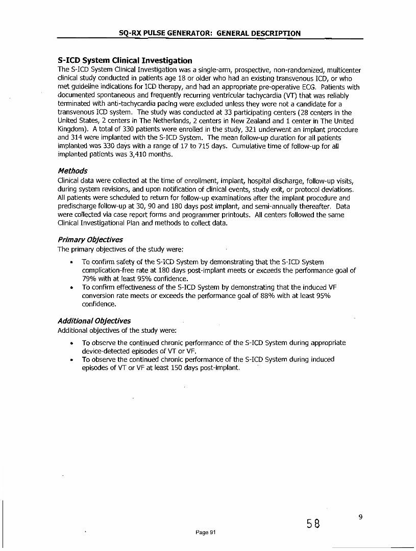
S-ICD System Clinical InvestigationThe S-ICD System Clinical Investigation was a single-arm, prospective, non-randomized, multicenterclinical study conducted in patients age 18 or older who had an existing transvenous ICD, or whomet guideline indications for ICD therapy, and had an appropriate pre-operative ECG. Patients withdocumented spontaneous and frequently recurring ventricular tachycardia (VT) that was reliablyterminated with anti-tachycardia pacing were excluded unless they were not a candidate for atransvenous ICD system. The study was conducted at 33 participating centers (28 centers in theUnited States, 2 centers in The Netherlands, 2 centers in New Zealand and 1 center in The UnitedKingdom). A total of 330 patients were enrolled in the study, 321 underwent an implant procedureand 314 were implanted with the S-ICD System. The mean follow-up duration for all patientsimplanted was 330 days with a range of 17 to 715 days. Cumulative time of follow-up for allimplanted patients was 3,410 months.
MethodsClinical data were collected at the time of enrollment, implant, hospital discharge, follow-up visits,during system revisions, and upon notification of clinical events, study exit, or protocol deviations.All patients were scheduled to return for follow-up examinations after the implant procedure andpredischarge follow-up at 30, 90 and 180 days post implant, and semi-annually thereafter. Datawere collected via case report forms and programmer printouts. All centers followed the sameClinical Investigational Plan and methods to collect data.
Primary ObjectivesThe primary objectives of the study were:
* To confirm safety of the S-ICD System by demonstrating that the S-lCD Systemcomplication-free rate at 180 days post-implant meets or exceeds the performance goal of79% with at least 95% confidence.
* To confirm effectiveness of the S-ICD System by demonstrating that the induced VFconversion rate meets or exceeds the performance goal of 88% with at least 95%confidence.
Additional ObjectivesAdditional objectives of the study were:
* To observe the continued chronic performance of the S-ICD System during appropriatedevice-detected episodes of VT or VF.
* To observe the continued chronic performance of the S-ICD System during inducedepisodes of VT or VF at least 150 days post-implant.
589Page 91

SQ-RX PULSE GENERATOR: GENERAL DESCRIPTION
Accountability of PMA CohortOf 330 patients enrolled in PMA study, 321 underwent an implant procedure, of whom 314 wereimplanted with the S-ICD System. There were 293 patients still active at the time of database lockon February 14, 2012. The mean follow-up duration for all patients implanted was 330 days with arange of 17 to 715 days. Cumulative time of follow-up for all implanted patients was 3,410 months.The disposition of all study participants is summarized in Figure 1 below:
Enrolledn=330
Withdrawn Prior tob Implant Procedure
n=9
Implant Attemptn=321
Not Implantedn=7
(All 7 Withdrawn)
Implantedn=314
1 4 [ D iscontinuedn=21
(11 Explanted,2 Withdrawn,
8 Deaths)Activen=293
Figure 1: Summary of Patient Status as of 14 February, 2012
The primary safety endpoint analysis cohort includes ll patients who underwent an implant attemptfor the S-ICD System (N=321). The primary effectiveness endpoint cohort includes all patientsundergoing an implant attempt with complete acute induced VF conversion tests (N=304). A totalof 17 patients did not undergo (N =1) or complete (N=16) acute induced VF conversion testing,seven of which were ultimately not implanted.
1059
Page 92

SQ-RX PULSE GENERATOR: GENERAL DESCRIPTION
Study Population Demographics and Baseline ParametersThe demographics of the study population are typical for an ICD study performed in the US.Cardiovascular history included congestive heart failure (61.4%), hypertension (58.3%), andmyocardial infarction (41.4%). Secondary prevention ICD indications represented 20.6% of thepopulation. Subject demographics (Table 1), baseline characteristics (Table 2) and ICD Indications(Table 3) are described below.
Table 1: Subject demographics
Demographic Statistic/Category N=321
Mean ± SD (Median) 51.9 ± 15.5 (53.8Range 18.5-85.2
Gender Male 238 (74.1)
(n, O/)Female 83 (25.9)
White or Caucasian 208 (64.8)
Black or African American 76 (23.7)
Hispanic or Latino 23 (7.2)
Race(, 0 ) Asian 6(1.9)
Asian Indian 3 (0.9)
Maori 3(0.9)
Pacific Islander 2 (0.6)
h (Mean ± SD (Median) 174.3 ± 10.2 (175.0Range 142.2-200.7
Mean ± SD (Median) 90.5 + 25.2 (86.6Range 42.6-230.9
BMI Mean + SD (Median) 29.7 ± 7.2 (29.0)Range 15.2-69.0
19
PageS 63

SQ-RX PULSE GENERATOR: GENERAL DESCRIPTION
Table 2: Baseline Characteristics
Attribute Statistic/Category' N 321
Creatinine Mean ± SD (Median) 1.1 ± 0.4 (1.0)(mg/dL) Range 0.3-3.7
Ejection Mean ± SD (Median) 36.1 ± 15.9 (31.0)Fraction (0/6) Range 10.0-82.0(n=299)
I: No Physical Limitations 68 (21.2)
NYHA II: Slight Physical Limitations 146 (45.5)Classification III: Marked Physical 55(17.1)at Enrollment Limitations
(n, 0/6) IV: Total Physical Limitations 1 (0.3)
Unknown/Not Assessed 51 (15.9)
Atrial Fibrillation 49 (15.3)
COPD 27 (8.4)
Cancer 31 (9.7)
Congestive Heart Failure - 197 (61.4)Co-morbidities
History Diabetes . 90 (28.0)(n, 0/)
Hypertension 187 (58.3)
Myocardial Infarction 133 (41.4)
Stroke 18 (5.6)
Valve Disease 42 (13.1)
Ablation 16 (5.0)
CABG 48 (15.0)
Cardiac Surgical Defibrillator 43 (13.4)History
(n, %) Pacemaker 4(1.2)
PercutaneousRevascularization 9 (28.7)
Valve Surgery 18 (5.6)
12
61Page 94
SQ-RX PULSE GENERATOR: GENERAL DESCRIPTION
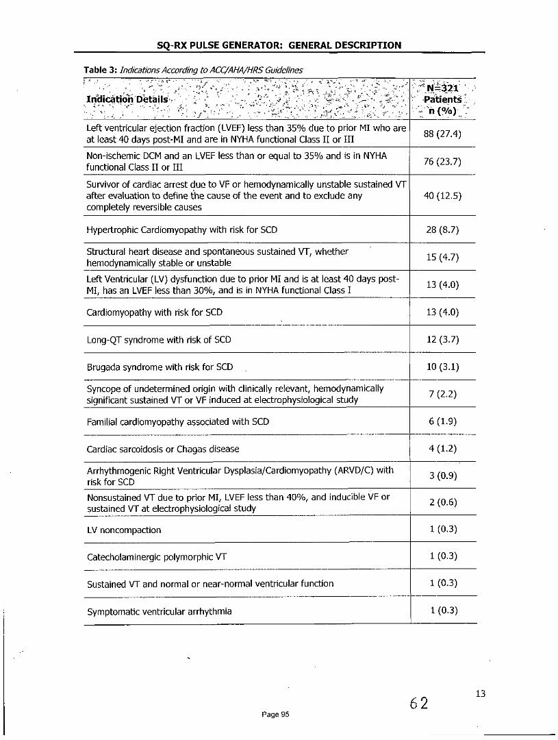
Table 3: Indicatons According to ACC/AIA/HRS Guidelines
N. N=321Indication Details - 7 Patients
Left ventricular ejection fraction (LVEF) less than 35% due to prior MI who are 88(27.4)at least 40 days post-MI and are in NYHA functional Class II or III
Non-ischemic DCM and an LVEF less than or equal to 35% and is in NYHA 76(23.7)functional Class II or III
Survivor of cardiac arrest due to VF or hemodynamically unstable sustained VTafter evaluation to define the cause of the event and to exclude any 40 (12.5)completely reversible causes
Hypertrophic Cardiomyopathy with risk for SCD 28 (8.7)
Structural heart disease and spontaneous sustained VT, whether 15 (4.7)hemodynamically stable or unstable
Left Ventricular (LV) dysfunction due to prior MI and is at least 40 days post- 13(4.0)MI, has an LVEF less than 30%, and is in NYHA functional Class I
Cardiomyopathy with risk for SCD 13 (4.0)
Long-QT syndrome with risk of SCD 12 (3.7)
Brugada syndrome with risk for SCD 10 (3.1)
Syncope of undetermined origin with clinically relevant, hemodynamically 7 (2.2)significant sustained VT or VF induced at electrophysiological study
Familial cardiomyopathy associated with SCD 6(1.9)
Cardiac sarcoidosis or Chagas disease 4(1.2)
Arrhythmogenic Right Ventricular Dysplasia/Cardiomyopathy (ARVD/C) with 3 (0.9)risk for SCD
Nonsustained VT due to prior MI, LVEF less than 40%, and inducible VF or 2 (0.6)sustained VT at electrophysiological study
LV noncompaction 1 (0.3)
Catecholaminergic polymorphic VT 1(0.3)
Sustained VT and normal or near-normal ventricular function 1(0.3)
Symptomatic ventricular arrhythmia 1(0.3)
6 2 13
Page 95
SQ-RX PULSE GENERATOR: GENERAL DESCRIPTION
Safety and Effectiveness Results
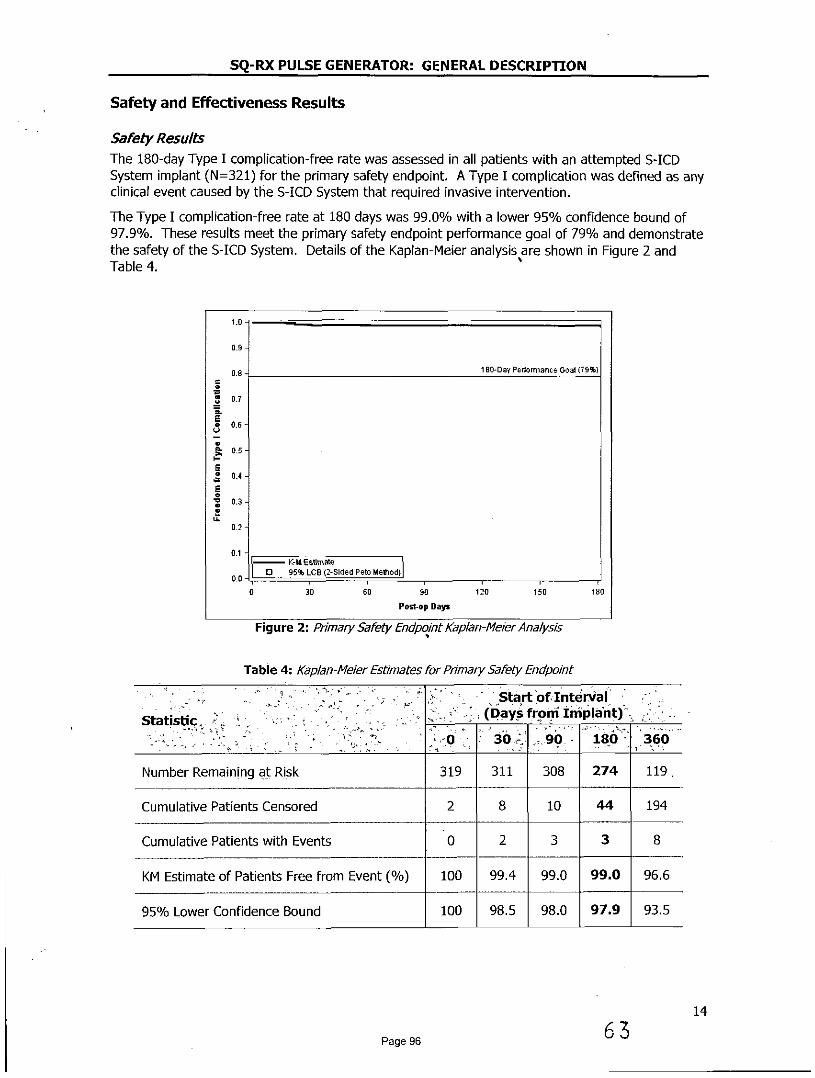
Safety ResultsThe 180-day Type I complication-free rate was assessed in all patients with an attempted S-ICDSystem implant (N=321) for the primary safety endpoint. A Type I complication was defined as anyclinical event caused by the S-ICD System that required invasive intervention.
The Type I complication-free rate at 180 days was 99.0% with a lower 95% confidence bound of97.9%. These results meet the primary safety endpoint performance goal of 79% and demonstratethe safety of the S-ICD System. Details of the Kaplan-Meier analysis are shown in Figure 2 andTable 4.
1.0
0.9
0.8- 180-Day Performance Goal (79%)
S0.7
0.7E
0.5
034
0-
00 1 0 95% LCB (2-Sided Peto Method)
0 30 60 90 120 150 180
Post-op Days
Figure 2: Primary Safety Endpoint Kaplan-Me/er Analysis
Table 4: Kaplan-Meier Estimates for Primary Safety Endpoint
Start of InteniStatistic (Days from nImplant)
0 30 90 180 360
Number Remaining at Risk 319 311 308 274 119
Cumulative Patients Censored 2 8 10 44 194
Cumulative Patients with Events 0 2 3 3 8
KM Estimate of Patients Free from Event (/) 100 99.4 99.0 99.0 96.6
95% Lower Confidence Bound 100 98.5 98.0 97.9 93.5
14
Page 96 63

SQ-RX PULSE GENERATOR: GENERAL DESCRIPTION
Clinical EventsA ClinicalEvent is defined as any untoward medical occurrence in a patient. An Observation is aclinical event that does not result in invasive intervention and a Complication is a clinical event thatresults in invasive intervention. All clinical events were classified by type based on the cause of theclinical event, according to the following definitions:
Type I: Caused by the S-ICD System
Type II: Caused by the S-ICD System user's manual or labeling of the S-ICD System
Type III: Not caused by the S-ICD System, but would not have occurred in the absenceof the implanted S-ICD System
Type IV: Caused by a change in the patient's condition
Table 5 summarizes all 211 clinical events reported from 139 patients, followed by a full listing of allType I, II and III clinical events in Table 6, Table 7 and Table 8, respectively.
Table 5: Clinical Event Summary by Type and Observation/ComplicationAll patients with an implant attempt (N=321)
C6mplications Observations Total
Clinical Event Eevents 'Patients (%) Evehts Patients (%) Events Patients (%)
Tvoe 1 12' 11 (3.4) 35 30 (9.3) 47 3(12.1)
Typ II 4 4(1.2) 0 0(0.0) 4 4 (1.2)
Type II 25 24 (7.5) 83 71 (22.1) 108 88 (27.4)
Type IV 16 15(4.7) 36 33(10.3) 52 44(13.7)
All Clinical Events 57 48 (15.0) 154 116 (36.1) 211 139 (43.3)
Of note, there were a total of 12 Type I Complications, eight (8) of which occurred within 180-days of implant and are shown in the primary safety Kaplan-Meier analysis (Figure 2). Theremaining four (4) events occurred after 360 days post-implant.
15
Page 97 6

SQ-RX PULSE GENERATOR: GENERAL DESCRIPTION
Table 6: Type I Clinical EventsAll patients with an implant attempt (N=321)
Complications Observations Total
Clinical Evernt Patients Patients PatientsEvents Events Events(/0) (%) G(%
Discomfort 3 3 (0.9) 8 7 (2.2) 11 11(3.4)
Inability to Communicate 2 2 (0.6) 0 0 (0.0) 2 2 (0.6)with the Device
Inappropriate Shock:Iveenapppia5 (1.6) 25 21 (6.5) 30 25 (7.8)Oversensing
Numbness at Device Site 0 0 (0.0) 1 1 (0.3) 1 1(0.3)
Premature Battery Depletion 2 2 (0.6) 0 0 (0.0) 2 2 (0.6)
Subcutaneous Emphysema 0 0 (0.0) 1 1 (0.3) 1 1(0.3)
All Type I Clinical Events 12 11 (3.4) 35 30 (9.3) 47 39 (12.1)
Table 7: Type !! Clinical EventsAll patients with an implant attempt (N=321)
Complications Observations Total
Clinical Event . Patients Patients PatientsEvents Eveeis Eventss - -nts P
Electrode Movement 2 2 (0.6) 0 0 (0.0) 2 2 (0.6)
Inappropriate ElectrodeCnaron c i toe e c e 1 1 (0.3) 0 0 (0.0) 1 1 (0.3)Connection to the Device
Sub-optimal Electrode 1 1(0.3) 0 0 (0.0) 1 1(0.3)Position
All Type II Clinical Events 4 4(1.2) 0 0(0.0) 4 4(1.2)
16
Page 98 65

SQ-RX PULSE GENERATOR: GENERAL DESCRIPTION
Table 8: Type III C/nical EventsAll patients with an implant attempt (N=321)
Complications Observations TotalClinca Event
Patients Patients Patients'Events Events Events 6.
(% (%) (%) , T'
Acute Hypoxic Respiratory 0(0.0) 1 1(0.3) 1 1(0.3)Failure
Adverse Reaction to 3 (0.9) 5 5 (1.6) 8 8 (2.5)Medication
Atrial Fibrillation / Flutter 0 0 (0.0) 14 14 (4.4) 14 14 (4.4)
Bleeding 0 0 (0.0) 1 1 (0.3) 1 1(0.3)
Discomfort 1 1(0.3) 12 12 (3.7) 13 12(3.7)
Electrode Movement 1 1(0.3) 0 0 (0.0) 1 1(0.3)
Fever 0 0 (0.0) 3 3 (0.9) 3 3 (0.9)
Hematoma 1 1 (0.3) 5 4(1.2) 6 5 (1.6)
Inadequate/ProlongedHndeaio onSied 3 3 (0.9) 2 2 (0.6) 5 5(1.6)Healing of Incision Site
Inappropriate Shock: SVTAbove Discrimination Zone 4 4 (1.2) 17 14 (4.4) 21 16 (5.0)(Normal Device Function)
Incision/Superficial 1 1 (0.3) 13 13 (4.0) 14 14 (4.4)Infection
Keloid 1 1 (0.3) 0 0 (0.0) 1 1(0.3)
Local Tissue Reaction 0 0 (0.0) 1 1(0.3) 1 1 (0.3)
Numbness at Device Site 0 0 (0.0) 1 1 (0.3) 1 1 (0.3)
PG Movement/Revision 1 1 (0.3) 0 0 (0.0) 1 1 (0.3)
Phantom Shock 0 0 (0.0) 5 3 (0.9) 5 3 (0.9)
Redness/Irritation 0 0 (0.0) 2 2 (0.6) 2 2 (0.6)
Stroke 0 0 (0.0) 1 1 (0.3) 1 1(0.3)
Sub-optimal PG and - 3 3 (0.9) 0 0 (0.0) 3 3 (0.9)Electrode Position
Sub-optimal Pulse 1 1(0.3) 0 0 (0.0) 1 1 (0.3)Generator Position
Suspected Worsening of 1 1 (0.3) 0 0 (0.0) 1 1 (0.3)Ischemia
System Infection 4 4(1.2) 0 0(0.0) 4 4(1.2)
All Type III Clinical 25 24 (7.5) 83 71 (22.1) 108 88 (27.4)Events
17
Page 99 66

SQ-RX PULSE GENERATOR: GENERAL DESCRIPTION
Device ExplantsEleven (11) patients exited the study after the S-ICD System was removed for: system infection (4),oversensing (2), pre-mature battery depletion (1), transvenous device implanted to provideoverdrive pacing for ventricular arrhythmia trigger suppression (1), elective explant due to thedevelopment of an indication for biventricular pacing (1), elective explant due to development ofhigh defibrillation threshold (1), and elective due to patient request (1).
Patient DeathsEight (8) deaths occurred in the study. None of the deaths were conclusively identified to beassociated with the device or procedure.
Effectiveness ResultsThe effectiveness of the S-ICD System was assessed by the proportion of patients with successfulacute (induced) VF conversion in all patients with an attempted S-ICD System implant (N=320). 2 Asuccessful VF conversion test required two consecutive VF conversions at 65 3 from four inductionattempts within a given shock polarity.
Of the 320 patients who underwent acute VF conversion testing, 16 patients3 yielded non-evaluableresults due to incomplete protocol testing. Of the 304 evaluable results, the S-LCD System acute VFconversion success rate was 100% with a lower 95% confidence bound of 98.8% (Table 9). Theseresults met the primary safety endpoint performance goal of 88% and demonstrate theeffectiveness of the S-LCD System.
Table 9: Effectiveness Endpoint Result - Acute VF Conversion RatePatients undergoing acute VF conversion testing (N=320)
Evaluable Results-Non-evaluable ER950/0 Clopper-PearsonEst mate (0/) Itra 06Results Itra %l . Successful Failure t
16 304 0 100.0 (98.8-100.0)
Of the 16 non-evaluable patients, 11 were associated with at least one failed conversion attempt at65 3 and, due to physician discretion, did not exhaust all of the protocol defined induction attemptsin both shock polarities. A sensitivity analysis was performed to impute these patients as failuresdespite incomplete testing, resulting in an imputed VF conversion success rate of 96.5%.
2 One (1) patient did not undergo testing at the discretion of the investigator.3 Seven (7) patients with non-evaluable tests were not implanted and 9 patients were implanted.
1867
Page 100

SQ-RX PULSE GENERATOR: GENERAL DESCRIPTION
Spontaneous EpisodesA total of 119 spontaneous VT/VF episodes in 21 patients were treated by the S-ICD Systemthrough February 14, 2012. A VT/VF episode refers to a device-declared episode in which devicerate/discrimination criteria were met in response to a ventricular tachyarrhythmia and therapy wasdelivered. A single episode may contain up to 5 shocks. The episode ends when the rollingaverage of the rate falls below the lowest programmed rate zone for 24 consecutive intervals.
For analysis, episodes were sub-divided into two classes: 1) discrete episodes that were temporallyindependent (<3 within 24 hours); and, 2) VT/VFstorms that comprise 3 or more treated VT/VFepisodes within 24 hours in the same patient. Of the 38 discrete device episodes, 35 (92.1%) wereconverted with the first shock and 37 (97.4%) were converted by any shock (Table 10). Oneepisode terminated spontaneously after an unsuccessful first shock (MVT). Four (4) VT/VF stormsfrom 2 patients resulted in 81 total device episodes, 40 of which were VF and stored in S-ICDSystem memory with the remaining 41 episodes not stored due to memory capacity limitations.Three (3) storms were ultimately converted by the S-ICD System and 1 was ultimately convertedwith an external defibrillation shock (Table 11).
Table 10: Conversion Effectiveness of Discrete Device Episodes (non-Storm)Patients with discrete episodes (N=16); Discrete device episodes (N=28)
R Device Episode Converted by Episode Converted byRym aEpisodes 1A Shock ( 0/a) Any Shock (/)
MVT 13 22 21(95.5) 21 (95.5)
PVT/VF 11 16 14(87.5) 16 (100.0)
Total 21 38 35 (92.1) 37 (97.4)
Table 11: Conversion of VT/VF StormsPatients with VT/VF Storms (N=2), Storm events (N=4), Stored Device episodes (N=40)
Patienlts VT/VF Storms Device Episodes FinalStorm.Pa-etp Conversion Method ()
S-ICD: 3 (75)
2 4 40 External: 1 (25)
Spontaneous Conversion: 0 (0)
Chronic Conversion SubstudyThe chronic performance of the S-ICD System was assessed by the proportion of patients withsuccessful conversion of induced VT/VF 150 days post-implant in all implanted patients whoprovided informed consent for this testing (N=78). Three (3) patients were excluded from theanalysis because they met the pre-specified definition of a non-evaluable test (did not completetesting in the opposite polarity after a failed 653 shock, as required by the protocol). All three wereconverted with a subsequent 80J S-ICD System shock.
The rate of successful conversion by a sub-maximal (65J) S-ICD System shock was 72/75 (96.0%).All 3/75 (4.0%) patients who failed to convert with a sub-maximal (65J) S-ICD System shock ineither polarity were successfully converted with a subsequent higher-energy S-ICD System shock.
68 19Page 101

SQ-RX PULSE GENERATOR: GENERAL DESCRIPTION
Subgroup AnalysesStepwise logistic regression models (backward elimination with a threshold p-value of 0.20) wereused to evaluate basic demographic characteristics (age, gender, African American race) andbaseline device programming (dual zone programming at hospital discharge) for statisticalassociations between with following safety-related outcomes:
* All Inappropriate shocks (n=41)* Inappropriate shocks for oversensing (n=25)* tnappropriate shocks for SVT (n=16)* Discomfort (n=22)* System and Superficial/Incision Infection (n=18)* Type I-III Complications (n=3S)
AgeAge was a significant predictor for inappropriate shocks. Patient who experience inappropriateshocks were younger with a mean age of 47 compared to a mean age of 53 for patients who didnot received any inappropriate shocks.
GenderFemale gender was significantly associated with a higher risk for device or procedure relateddiscomfort. Although the numbers are very small, it is notable that the inframammary crease wascited in 2 cases of female discomfort and the interface between the device site and the patient's brawas cited in another case.
RaceAfrican American race was not associated with device or procedure related complications.
Dual Zone Programming at DischargeDual zone programming at the time of hospital discharge was associated with significantly fewerinappropriate shocks than those programmed with a single zone. There was a 70% relativereduction of incidence for inappropriate shocks due to SVT with heart rates in the Shock only zoneand a 56% relative reduction of incidence for inappropriate shocks due to oversensing, whencompare to single zone programming.
ConclusionThe purpose of the S-ICD System Clinical Investigation was to evaluate the safety, effectivenessand chronic performance of the S-ICD System. There were 330 patients enrolled in the study and321 underwent an implant procedure. The 314 patients implanted with the S-ICD Systemgenerated 3,410 months of patient data.
The data demonstrate that the S-ICD System operates appropriately per design for the S-ICDSystem's intended uses and as described in the S-ICD System's labeling. All objectives of the S-ICDSystem Clinical Investigation were met demonstrating safety and effectiveness of the S-ICD System.
2069
Page 102

SQ-RX PULSE GENERATOR: GENERAL DESCRIPTION
Patient ScreeningThe patient screening tool (Figure 3) is a customized measurement tool made of transparentplastic printed with colored profiles. The profiles are designed to ensure appropriate deviceperformance by identifying signal characteristics that may lead to unsatisfactory detectionoutcomes for a patient before implant. The patient screening process is completed in three steps:(1) Collecting the surface ECG, (2) Evaluating the surface ECG and (3) Determining an acceptablesense vector.
The patient screening tool can be obtained from any Cameron Health representative or by callingthe Customer Service Department.
lii Cl ICY;SSAR AE in 2. RR FRCM RSERLNCE .RKCA.
14c GUIDE!Not.. FixSfelfy EGG eldoe hoid nt s tend beytd 14 anaivsjV
Figure 3: Patient Screening Tool
21
Page 103 10

SQ-RX PULSE GENERATOR: GENERAL DESCRIPTION
Collecting the Surface ECG1. In order to perform the patient screening process, a surface equivalent of the
subcutaneous sensing vectors must be obtained. It is important to collect the surfaceECG in the location that represents the intended position of the implanted S-ICD System.When placing the S-ICD System in the typical implant location, the surface ECG electrodeshould be positioned as described below (Figure 4). If a non-standard S-ICD Systemelectrode or pulse generator placement is desired, the surface ECG electrode locationsshould be modified accordingly.
* ECG Electrode LL should be placed in a lateral location, at the 5thintercostal space along the mid-axillary line to represent the intendedlocation of the implanted pulse generator.
* ECG Electrode LA should be placed 1 cm left lateral of the xiphoidmidline to represent the intended location of the proximal sensing nodeof the implanted electrode.
* ECG Electrode RA should be placed 14 cm superior to the ECGElectrode LA, to represent the intended position of the distal sensing tipof the implanted electrode. A 14 cm guide is located at the bottom ofthe transparent screening tool.
A3
Figure 4: Typical placement of surface ECG electrodes for patent screening
2. Using a standard ECG machine, record 10 - 20 seconds of ECG using Leads I, II and IIIwith a sweep speed of 25 mm/sec and ECG gain between 5 - 20 mm/mV (use thelargest ECG gain that does not result in clipping).Note: It is important to establish a stable baseline when collecting the surface ECG. Ifa wandering baseline is noted ensure that the appropriate ground electrodes from theECG machine are attached to the patient. To yield an acceptable signal for testng, thegain may be adjusted for each ECG lead independently
3. Record ECG signals in at least two postures: (1) Supine and (2) Standing. Other posturesmay be collected including: Seated, Left Lateral, Right Lateral, and Prone.Note: If the S-ICD System is to be implanted with a concomitant pacemaker, allventricular morphologies (paced and intinsic, if normal conduction is expected) shouldbe collected
22
Page 104 71

SQ-RX PULSE GENERATOR: GENERAL DESCRIPTION
Evalualtng the Surface ECGEach surface ECG should be evaluated by analyzing at least 10 seconds of QRS complexes. Ifmultiple morphologies are noted (e.g., bigeminy, pacing, etc.), all morphologies should betested as described below before the vector is deemed acceptable.
Each QRS complex is evaluated as follows:
1. Select the colored profile from the Patient Screening Tool that best matches theamplitude of the QRS (Figure 5). For biphasic signals, the larger peak should be used todetermine the appropriate colored profile. The QRS peak must fall within the windowbounded by the dotted line and the peak of the colored profile.Note: ECG gains > 20 mm/mV are not permitted If, when printed at the maximum 20mm/rmVga/n, the QRS peak does not reach the minimum boundary (dotted line) of thesmallest colored profile, that QRS complex is deemed unacceptable
Figure 5: Selecting the colored proflle
2. Align the left edge of the selected colored profile with the onset of the QRS complex.The horizontal line on the colored profile should be used as a guide for isoelectricbaseline alignment.
3. Evaluate the QRS complex. If the entire QRS complex and trailing T-wave are containedwithin the colored profile, the QRS is deemed acceptable. If any portion of the QRScomplex or trailing T-wave extends outside of the colored profile, the QRS is deemedunacceptable (Figure 6).
UNACCEPTABLE ACCEPTABLELEAD LEAD
Figure 6: Evaluating the QRS complex
4. Repeat the above steps with all QRS complexes collected with all surface ECG leads inall collected postures.
23
Page 105 7 2

SQ-RX PULSE GENERATOR: GENERAL DESCRIPTION
Determining an Acceptable Sense VectorEach collected surface ECG lead represents a sense vector of the S-ICD System. Evaluateeach surface ECG lead independently for acceptability. A surface ECG lead (sense vector)should be deemed acceptable only if all of the following conditions are met:
* All tested QRS complexes and morphologies from the surface ECG lead(sense vector) must pass the QRS evaluation.
* The morphology of the intrinsic/paced QRS complex is stable acrosspostures. No significant change to the QRS complex is noted as a resultof postural changes.
* The surface ECG lead (sense vector) must be deemed acceptable in alltested postures.
A patient is considered suitable for implant of the S-ICD System if at least one surface ECG lead(sense vector) is acceptable for all tested postures.
Note: Special circumstances may present in which the physician elects toproceed with the implantation of the S-ICD System despite failingthe screening process. In this case, careful attention should beapplied to the device setup process of the S-ICD System as the riskof poor sensing and/or inappropriate shock is increased
7324Page 106

SQ-RX PULSE GENERATOR: OPERATION
GeneralThe S-ICD System is designed for ease of use and simplicity of patient management. Thearrhythmia detection system employs up to two rate zones, and the device has a singleautomatic response to a detected ventricular tachyarrhythmia - a nonprogrammable, maximum-energy, biphasic shock of 80 1 The device has a number of automatic functions designed toreduce the amount of time required for implantation, initial programming and patient follow-up.
Modes of OperationThe device has three modes of operation:
* Shelf* Therapy On* Therapy Off
Shelf ModeThe Shelf mode is a low power consumption state intended for storage only. Whencommunication is initiated between the device and the programmer, a full-energy capacitorreformation is performed and the device is prepared for set-up. Once the device is taken out ofShelf mode, it cannot be reprogrammed back into Shelf mode.
Therapy On ModeThe Therapy On mode is the primary operating mode of the device, allowing automatic detectionof and response to ventricular tachyarrhythmias. All device features are active.
Note: The device must be programmed out of Shelf mode before beingprogrammed to Therapy On.
Therapy Off ModeThe Therapy Off mode disables automatic therapy delivery and enables manual control of shockdelivery. Programmable parameters may be viewed and adjusted via the programmer. Also, thesubcutaneous electrogram (S-ECG) may be displayed or printed.
The device automatically defaults to Therapy Off when taken out of Shelf mode.Note: Manual and rescue shock therapy are available only after the initial
Setup process is complete. Refer to the Q-TECH Programmer User'sManual for details.
74 25
Page 107

SQ-RX PULSE GENERATOR: OPERATION
Sensing Configuration and Gain SelectionDuring the Automatic Setup process, the device automatically selects an optimal sensing vectorbased on an analysis of cardiac signal amplitude and signal-to-noise ratio. This analysis isperformed on the three available vectors:
* Primary: Sensing from the proximal electrode ring on theelectrode to the active surface of the device.
* Secondary: Sensing from the distal sensing electrode ring on theelectrode to the active surface of the device.
* Alternate: Sensing from the distal sensing electrode ring to theproximal sensing electrode ring on the electrode.
The sensing vector can also be selected manually. The Q-TECH Programmer User's Manualprovides instructions for sensing vector selection.
The device automatically selects an appropriate gain setting during the Automatic Setup process.The gain can also be manually selected, as further explained in the Q-TECH Programmer User'sManual. There are two gain settings:
* Ix Gain (+4 mV): Selected when the signal amplitude is clipped atthe 2x gain setting.
* 2x Gain (±2 mV): Selected when the signal amplitude is not clippedat this setting.
Sensing and Tachyarrhythmia DetectionThe device is designed to prevent inappropriate therapy delivery as a result of noise sensing ormultiple counting of individual cardiac cycles. This is accomplished by an automatic analysis ofsensed signals, which includes event detection, certification and decision phases.
Detection PhaseDuring the Detection Phase, the device uses a detection threshold to identify sensed events. Thedetection threshold is automatically adjusted continuously using amplitudes of recently detected'electrical events. In addition, detection parameters are modified to increase sensitivity whenrapid rates are detected. Events detected during the Detection Phase are passed on to theCertification Phase.
Certification PhaseThe Certification Phase examines the detections and classifies them as certified cardiac events oras suspect events. Certified events are used to ensure that an accurate heart rate is passed tothe Decision Phase. A suspect event can be one whose pattern and/or timing indicates the signalis caused by noise, such as a muscle artifact or some other extraneous signal. Events are alsomarked as suspect if they appear to derive from double or triple detections of single cardiacevents. The device is designed to identify and correct multiple detections of wide QRS complexesand/or erroneous detections of a T-wave.
Decision PhaseThe Decision Phase examines all certified events and continuously calculates a running four R-to-R interval average (4 RR average). The 4 RR average is used throughout the analysis as anindicator of the heart rate.
75 26
Page 108

SQ-RX PULSE GENERATOR: OPERATION
Therapy ZonesThe device allows the selection of rate thresholds that define a Shock Zone and an optionalConditional Shock Zone. In the Shock Zone, rate is the only criterion used to determine if arhythm will be treated with a shock. The Conditional Shock Zone has additional discriminatorsused to determine if a shock is warranted to treat an arrhythmia.
The Shock Zone is programmable from 170 - 250 bpm in increments of 10 bpm. The ConditionalShock Zone must be lower than the Shock Zone, with a range of 170 - 240 bpm in increments of10 bpm.
Note: To ensure proper detection of VF, program the Shock Zone orConditional Shock Zone to 200 bpm or less
Note: The IDE Study demonstrated a significant reduction in inappropriatetherapy with the activation of the Conditional Shock Zone prior tohospital discharge (see S-ICD System Clnical Investigation, page 9).
Graphically, the use of a Shock Zone and Conditional Shock Zone is shown below (Figure 7):
Figure 7: Shock Zone Rate Detection Diagram
The device declares a Tachycardia when the 4RR average enters either therapy zone.
Once a Tachycardia is declared, the 4RR average must become longer (in ms) than the lowestrate zone, plus 40 ms for 24 cycles for the device to consider the episode to have ended. In theShock Zone, treatable arrhythmias are determined by rate alone.
7 6 27
Page 109

SQ-RX PULSE GENERATOR: OPERATION
Analysis in the Conditional Shock ZoneIn contrast, rate and morphology are analyzed in the Conditional Shock Zone. The ConditionalShock Zone is designed to discriminate between treatable and other high-rate events such asatrial fibrillation, sinus tachycardia and other supraventricular tachycardias.
A normal sinus rhythm template (NSR Template) is formed during device initialization. This NSRtemplate is used during analysis in the Conditional Shock Zone to identify treatable arrhythmias.In addition to morphology comparison with the NSR template, other morphologic analysis is usedto identify polymorphic rhythms. Morphology and QRS width are used to identify monomorphicarrhythmias such as ventricular tachycardia. If the Conditional Shock Zone is enabled, then anarrhythmia is found to be treatable according to the decision tree shown below (Figure 8):
Certification Phase
Compare currentCompare Current Poor Match Certified Event and Good Match Compare QRS
Previous Certified Width to Thresholdand NSR Template EventCertifed Evet _ K erffieEvent
a>K>
Good Match Poor Match Narro Wide
Label "5": Label "1": Label "": Label "T":Normal Sensed Event Tachy Detection Normal Sensed Event Wide QRS TreatableNon-Treatable Event Treatable Event Non-Treatable Event Event
Figure 8: Decision tree for determining treatable arrhythmias in the Conditional Shock Zone
For some patients, a NSR Template may not be formed during device initialization as a result ofvariability in their cardiac signal at resting heart rates. For such patients, the device uses beat-to-beat morphology and QRS width analysis for arrhythmia discrimination.
Charge ConfirmationThe device must charge the internal capacitors before shock delivery. Confirmation of theongoing presence of a tachyarrhythmia requires monitoring a moving widow of the 24 mostrecent intervals defined by certified events. Charge confirmation employs an X (treatable interval)out of Y (total intervals in the window) strategy to accomplish this. If 18 of the 24 most recentintervals are found to be treatable, the device begins to analyze rhythm persistence. Persistenceanalysis requires the X out of Y condition be maintained or exceeded for at least two consecutiveintervals; however, this value may be increased as a result of Smart Charge, as explained below.
Capacitor charging is initiated when the following three conditions are met:1. X of Y criterion is satisfied.2. Persistence requirement is satisfied.3. The last two certified intervals are in the treatable zone.
28
Page 110

SQ-RX PULSE GENERATOR: OPERATION
Therapy DeliveryRhythm analysis continues throughout the capacitor charging process. Therapy delivery isaborted if the 4 RR average interval becomes longer (in ms) than the lowest rate zone plus 40ms for 24 intervals. When this occurs, an untreated episode is declared and a Smart Chargeextension is incremented, as explained below.
Capacitor charging continues until the capacitor has reached its target voltage, at which timereconfirmation is performed. Reconfirmation is used to ensure that the treatable rhythm did notspontaneously terminate during the charging cycle. Reconfirmation requires the last threeconsecutive detected intervals (regardless of whether the intervals are certified or suspect) to befaster than the lowest therapy zone. If non-treatable events are detected during or after thecharging sequence, reconfirmation is automatically extended, one interval at a time, up to amaximum of 24 intervals.
Reconfirmation is always performed and shock delivery is non-committed until reconfirmation iscomplete. Once the criteria for reconfirmation is met, the shock is delivered.
Smart ChargeSmart Charge is a feature that automatically increases the Persistence requirement by threeintervals each time an untreated episode is declared, up to a maximum of five extensions. Thus,after an untreated episode, the requirement to start capacitor charging becomes more stringent.The Smart Charge extension value can be reset to its nominal value (zero extensions) using theprogrammer. The Smart Charge feature cannot be disabled, though it is not used for the secondand later shocks that occur during any given episode.
RedetectionA blanking period is enabled following delivery of a high-voltage shock. After delivery of the firstshock, up to four additional shocks will be delivered if the episode does not terminate. Rhythmanalysis for delivering shocks 2 - 5 generally follows the detection steps described above, withthe following exceptions:
1. Following the first shock delivery, the X/Y criterion is modified to require 14 treatableintervals in the last 24 (14/24), rather than 18.
2. The Persistence Factor is always set to two intervals (i.e., not modified by the SmartCharge feature).
Shock Waveform and PolarityThe shock waveform is biphasic, with a fixed tilt of 50%. The shock is delivered synchronouslyunless a 1000 ms time out expires without an event being detected for synchronization, at whichtime the shock is delivered in an asynchronous manner.
The device is designed to automatically select the appropriate polarity for therapy. Both standardand reversed polarity shocks are available. If a shock fails to convert the arrhythmia andsubsequent shocks are required, polarity is automatically reversed for each successive shock. Thepolarity of the successful shock is then retained as the starting polarity for future episodes.Polarity can also be selected during the Induction and Manual Shock process to facilitate device-based testing.
7 8 29
Page 111

SQ-RX PULSE GENERATOR: OPERATION
Post-Shock Bradycardia Pacing TherapyThe device provides optional post-shock, on-demand bradycardia pacing therapy. When enabledvia the programmer, bradycardia pacing occurs at a non-programmable rate of 50 bpm for up to30 seconds. The pacing output is fixed at 200 mA, and uses a 15 ms biphasic waveform.
Pacing is inhibited if the intrinsic rate is greater than 50 bpm. In addition, post-shock pacing isterminated if a tachyarrhythmia is detected or a magnet is placed over the device during thepost-shock pacing period.
Manual and Rescue Shock DeliveryUpon programmer command, the device can deliver manual and rescue shocks. Manual shocksare programmable from 10 to 80 J delivered energy in 5 1 steps. Rescue shocks are non-programmable, delivering the maximum output of 80 1.
Note: The Rescue Shock will not be inhibited with magnet application.Refer to the S-ICD System Magnet Model 4520 section for completeinformation.
Additional Features of the S-ICD SystemThis section presents descriptions of several additional features available in the S-ICD System.
Auto Capacitor ReformationThe device automatically performs a full-energy (80 J) capacitor reformation when taken out ofShelf mode and every four months until the device reaches End of Life (EOL). The energy outputand reformation time interval are non-programmable. The Auto Capacitor Reformation interval isreset after any 80 J capacitor charge is delivered or aborted.
Internal Warning System - Beeper ControlThe device has an internal warning system (beeper) that emits an audible tone to alert thepatient to certain device conditions that require prompt consultation with the physician. Theseconditions include:
* Elective Replacement (ERI) and End of Life (EOL) indicators* Electrode impedance out of range* Prolonged charge times* Failed Device Integrity Check* Irregular battery depletion
This internal warning system is automatically activated at time of implant. Once triggered, thebeeper sounds for 16 seconds every nine hours until the trigger condition has been resolved. Ifthe triggering condition reoccurs, then the tones will once again alert the patient to consult thephysician. The beeper can be disabled via the programmer once ERI is reached.
Note: The beeper may be activated by applying a magnet over the deviceto elicit the beeping tones. Patients should be educated to contacttheir physician immediately whenever the beeper is heard
Arrhythmia InductionThe device facilitates testing by providing the capability to induce a ventricular tachyarrhythmia.Via the programmer, the implanted system can deliver a 200 mA output at a frequency of 50 Hz.The maximum length of stimulation is 10 seconds.
Note: Induction requires that the device be programmed to Therapy On.
30
Page 112
SQ-RX PULSE GENERATOR: OPERATION
System DiagnosticsThe S-ICD System automatically performs a diagnostic check at scheduled intervals.
Electrode ImpedanceElectrode impedance is measured each time a shock is delivered. In addition, a lead electrodeintegrity test is performed once a week. The shock impedance values are stored and displayed inthe episode data and summary report.
Note: If the device is taken out of Shelf mode, but not Implanted, theinternal warning system will be activated due to the weeklyautomatic measurements of Impedance. Devite beeping due to thismechanism is normal behavior.
Device Integrity CheckThe Device Integrity Check is automatically performed daily by the implanted system, and alsoeach time the programmer links to an implanted device. This test scans for any unusualconditions in the device and, if any are detected, the system provides a notification either via thedevice's internal warning system or on the programmer screen.
Battery Performance Monitoring SystemThe device automatically monitors battery status to provide notice of impending batterydepletion. Two indicators are provided via messages on the programmer, each activated bydeclining battery voltage. ERI and EOL are also signaled by activation of the device's beeper.
Elective Replacement Indicator (ERI): When the ERI is detected,the device will provide therapy for at least three months, if no more thansix maximum energy charges/shocks occur. The patient should bescheduled for replacement of the device.
End of Life (EOL): When the EOL indicator is detected, the deviceshould be replaced immediately. Therapy may not be available whenEOL is declared.
3180
Page 113

SQ-RX PULSE GENERATOR: OPERATION
Storing and Analyzing DataThe device stores S-ECGs for up to 24 treated and 20 untreated tachyarrhythmia episodes. Thenumber of treated episodes, untreated episodes, and the therapy shocks delivered since the lastfollow-up procedure and initial implant are recorded and stored. Through wireless communicationwith the programmer, the stored data is retrieved for analysis and report printouts.
Note: Episodes that occur during communication with the programmer willnot be stored.
Note: SVT episodes with heart rates lower than and within the ConditionalShock zone are not stored
Treated EpisodesUp to 128 seconds of S-ECG data is stored for each treated episode:
* First Shock: 44 seconds prior to capacitor charging, up to 24 secondsprior to shock delivery and up to 12 seconds of post-shock S-ECG.
* Subsequent Shocks: A minimum of 6 seconds of pre-shock and up to 6seconds post-shock S-ECG.
Untreated EpisodesFor untreated episodes, 44 seconds of pre-episode and up to 24 seconds of episode S-ECG arestored. A retum to normal sinus rhythm during an untreated episode halts S-ECG storage.
Captured S-ECGThe S-ECG can be captured in real time on rhythm strips when the device is actively linked viawireless telemetry to the programmer. Up to five 12-second recordings of S-ECG can be stored.
S-ECG Rhythm Strip MarkersThe system provides S-ECG annotations (Table 12) to identify specific events during a recordedepisode. Sample annotations are shown for the programmer display (Figure 9) and the printedreport (Figure 10).
Table 12: S-ECG Rhythm Stfip Markers
Chaing C x I
seed.Beat s t
Noisy Beat NFigure 9: Programmer Display Markers
Paced Beat P
U hyDetection T
Return to NSR a x_ Figure 10: Printed Report Markers
32
Page 114
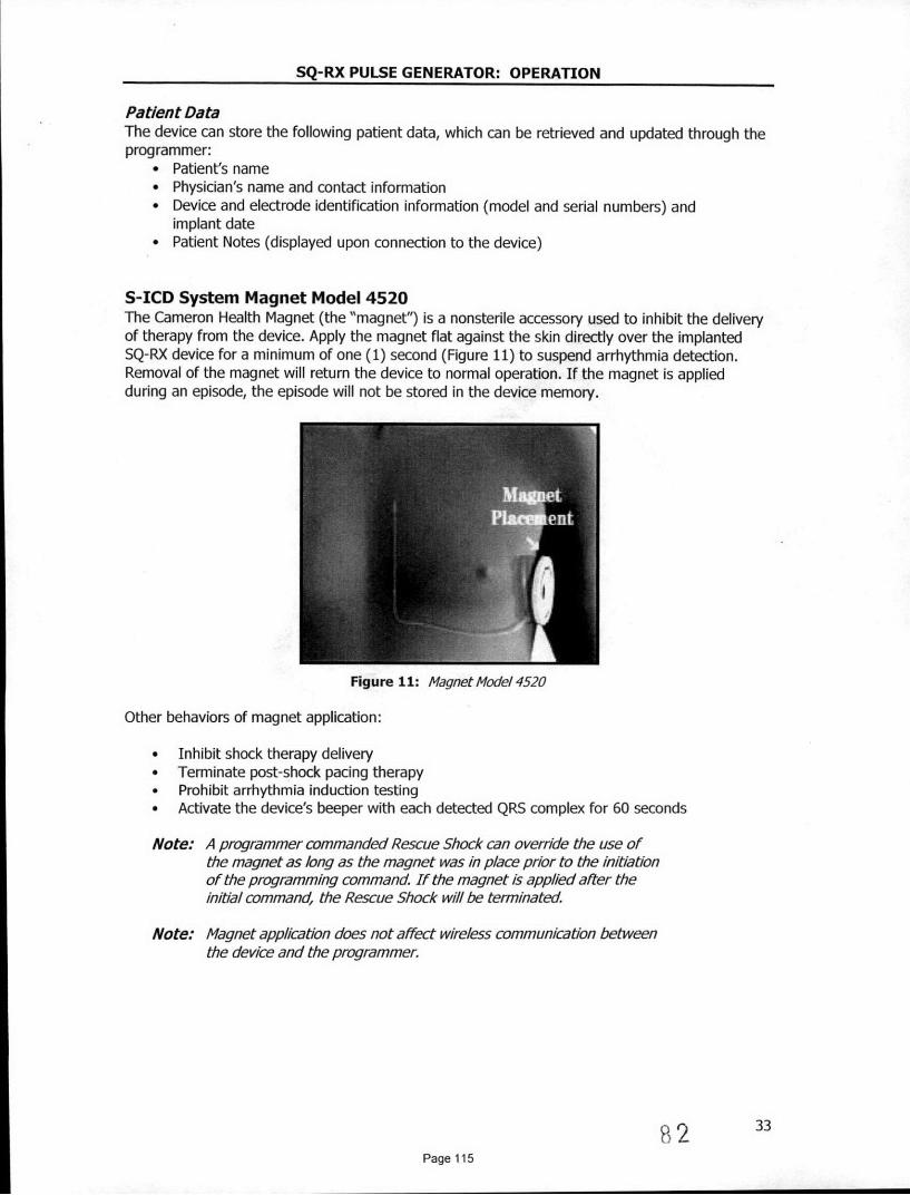
SQ-RX PULSE GENERATOR: OPERATION
Patient DataThe device can store the following patient data, which can be retrieved and updated through theprogrammer:
* Patient's name* Physician's name and contact information* Device and electrode identification information (model and serial numbers) and
implant date* Patient Notes (displayed upon connection to the device)
S-ICD System Magnet Model 4520The Cameron Health Magnet (the "magnet") is a nonsterile accessory used to inhibit the deliveryof therapy from the device. Apply the magnet flat against the skin directly over the implantedSQ-RX device for a minimum of one (1) second (Figure 11) to suspend arrhythmia detection.Removal of the magnet will return the device to normal operation. If the magnet is appliedduring an episode, the episode will not be stored in the device memory.
Figure 11: Magnet Mode/ 4520
Other behaviors of magnet application:
* Inhibit shock therapy delivery* Terminate post-shock pacing therapy* Prohibit arrhythmia induction testing* Activate the device's beeper with each detected QRS complex for 60 seconds
Note: A programmer commanded Rescue Shock can override the use ofthe magnet as long as the magnet was in place prior to the initiationof the programming command If the magnet is applied alter theinitial command, the Rescue Shock will be terminated
Note: Magnet application does not affect wireless communication betweenthe device and the programmer
82 3Page 115

SQ-RX PULSE GENERATOR: USING THE SQ-RX PULSE GENERATOR
Implanting the S-ICD SystemThis section presents the information necessary for implanting and testing the S-ICD System,including:
* Implanting the SQ-RX Pulse Generator (the "device")* Implanting the Q-TRAK Subcutaneous Electrode (the "electrode") using
the Q-GUIDE Subcutaneous Electrode Insertion Tool (the "EIT")* Setting up and testing the device using the Q-TECH Programmer (the
"programmer"). Refer to the Q-TECH Programmer User's Manual foradditional information.
The S-ICD System is designed to be positioned using anatomical landmarks. However, it isrecommended to review a pre-implant chest x-ray in order to confirm that a patient does nothave notably atypical anatomy (e.g. dextrocardia). Additionally, it is not recommended to deviatefrom the implant instructions to accommodate for physical body size or habitus, unless a pre-implant chest x-ray has been reviewed.
The device and electrode are typically implanted subcutaneously in the left thoracic region(Figure 12). The EIT is used to create the subcutaneous tunnels in which the electrode isinserted.
Figure 12: Placementof the S-CD System
Creating the Device PocketThe device is implanted in the left lateral thoracic region. To create the device pocket, make anincision such that the device can be placed in the vicinity of the left 5 and 6t intercostal spacesand near the mid-axillary line (Figure 13). This can be accomplished by making an incision alongthe inframammary crease.
Figure 13: Creating the device pocket
83Page 116

SQ-RX PULSE GENERATOR: USING THE SQ-RX PULSE GENERATOR
Implanting the Q-7X4K Subcutaneous ElectrodeThe procedure described below is one of several surgical approaches that can be used toappropriately implant and position the electrode. Regardless of the surgical approach, thedefibrillation coil must be positioned parallel to the sternum, approximately 2 cm from the sternalmidline (Figure 12).
1. Make a small, 2 cm horizontal incision at the xiphoid process (xiphoid incision)Note: If desired, in order to facilitate attachment of the suture sleeve to
the fasda following electrode placement, two suture des to thefascia can be made at the xiphold incsion prior to continuing.
2. Insert the distal tip of the Er at the xiphoid incision and tunnel laterally until the distal tipemerges at the device pocket.Note: The ErT is malleable and can be curved to match the patient's
anatomical profie.
3. Using conventional suture material, tie the anchoring hole of the electrode to the EITcreating a long 15-16 cm loop (Figure 14).
Figure 14: Connecting distal end of electrode to the EIT
4. With the electrode attached, carefully pull the Err back through the tunnel to the xiphoidincision until the proximal sensing electrode emerges.
5. Place a suture sleeve over the electrode shaft 1 cm below the proximal sensing electrode.Using the preformed grooves, bind the suture sleeve to the electrode shaft using 2-0 silk orsimilar non-absorbable suture material, making sure not to cover the proximal sensingelectrode. Check the suture sleeve after anchoring to assure stability by grasping the suturesleeve with fingers and try to move the electrode in either direction.Note: Do not secure the suture sleeve and electrode to the fascia until
electrode placement is complete
6. Make a second incision approximately 14 cm superior to the xiphoid incision (superiorincision). If desired, place the exposed electrode on the skin to make this measurement. Thedistance between the superior and xiphold incisions must accommodate the portion of theelectrode from the distal sensing electrode to the proximal sensing electrode.
84 35Page 117

SQ-RX PULSE GENERATOR: USING THE SQ-RX PULSE GENERATOR
7. Insert the distal tip of the EIT into the xiphoid incision and tunnel subcutaneously towardsthe superior incision (Figure 15).
Figure 15: Tunneing to superior incision
8. Once the distal tip of the EIT emerges from the superior incision, disconnect and retain thesuture loop from the distal tip of the EIT. Secure the ends of the suture with a surgicalclamp. Remove the EIT.
9. Using the secured suture at the superior incision, carefully pull the suture and electrodethrough the tunnel until the electrode's anchoring hole emerges. The electrode should beparallel to the sternal midline.
10. Cut and discard the suture material.
11. At the xiphoid incision, secure the suture sleeve with the electrode to the fascia using 2-0 silkor similar non-absorbable suture material.Note: Ensure that the suture is securely fastened to fascia by gently
tugging on the suture prior to tying to the suture sleeve andelectrode.
12. At the superior incision, secure the anchoring hole to the fascia using 2-0 silk or similar non-absorbable suture material (Figure 16).
Figure 16: Andoring the distal electrode bio
Note: Ensure that the suture is securely fastened to fascia by gentlytugging on the suture prior to tying to the electrode anchoring hole.
13. Gently tug the electrode at the superior incision to ensure the anchoring hole is secured tothe fascia.
14. To dispose of the EIT, return the used product to the original package, then dispose in abiohazard container.
3685
Page 118

SQ-RX PULSE GENERATOR: USING THE SQ-RX PULSE GENERATOR
Connecting the Electrode to the Device
Note: Avoid a/lowing blood or other body fluids to enter the connector portin the device header. If blood or other body fluids inadvertentlyenter the connector port, flush with sterile water.
Note: Do not implant the device If the set screw sealplug appears to bedamaged.
1. Grip the electrode close to the electrode connector pin and insert it straight into theconnector port. Minimize bending or buckling of the electrode during insertion.
2. Ensure that the electrode pin is well past the innermost connector ring in the header (Figure17). When viewed from the top of the header, the distal pin should extend past theconnector ring, at least half way to the end of the electrode cavity.
Correct Pin Placement Incorrect Pin Placement
Figure 17: Posiion of te elecnde pin
3. Use the torque wrench to tighten the set screw in a clockwise motion (Figure 18). The torquewrench is designed to apply the proper amount of force to the set screw. Tighten the setscrew until the wrench ratchet clicks.
Figure 18: Using torque wrench to tighten set screw
Note: When connecting the electrode to the device, use only the toolsprovided in the device tray. Failure to use the supplied tools mayresult in damage to the set screw. Retain the tools until all testingprocedures are complete and the device is implanted.
4. Gently tug on the electrode body to confirm a secure connection.
5. Insert the device into the subcutaneous pocket, with any excess electrode placed underneaththe device.
86 3Page 119

SQ-RX PULSE GENERATOR: USING THE SQ-RX PULSE GENERATOR
6. Anchor the device to the fascia to prevent possible migration using conventional 0-silk orsimilar non-absorbable suture material. A suture hole is provided in the header for thispurpose (Figure 19).
Figure 19: Anchoring the device using header suture hole
7. Refer to the Q-TECH Programmer User's Manual for instructions for set-up and/or inductiontesting.Note: Initial set-up Is recommended at implant.
8. After device set-up, close all incisions using standard suture protocol (Figure 20).
Figure 20: System placement alter closure of all inisvons
38
Page 120 87

SQ-RX PULSE GENERATOR: USING THE SQ-RX PULSE GENERATOR
Setting Up the SQ-RX Pulse GeneratorA brief set-up process must be completed before the device can deliver manual or automatictherapy. This process can be performed automatically or manually during the implant procedure,although Automatic Set-up is recommended. During set-up, the system automatically:
* Confirms entry of the subcutaneous electrode model and serial numbers* Measures the shock electrode impedance* Optimizes the sense electrode configuration* Optimizes the gain selection* Acquires a reference NSR template
Instructions for completing this process can be found in the Q-TECH Programmer User's Manual.
Defibrillation TestingOnce the device is implanted and Automatic Therapy is programmed On, defibrillation testingmay be conducted. A 15J safety margin is recommended for defibrillation testing.
Note: Defibrillation testing is recommended at implant to confirm theability of the S-ICD System to sense and convert VF
If appropriate sensing or VF conversion cannot be demonstrated, consider relocating theelectrode or device and retest. VF conversion testing can be conducted in either polarity. Referto the Q-TECH Programmer User's Manual for instructions for set-up and induction testing.
Post Implant Follow-Up ProceduresDuring a follow-up procedure, it is recommended that the location of the electrode be periodicallyverified by palpation and/or X-ray. When device commnunication with the programmer isestablished, the programmer automatically notifies the physician of any unusual conditions. Referto the Q-TECH Programmer User's Manual for more information.
Patient management and follow-up are at the discretion of the patient's physician, but arerecommended at least every 3 months to monitor the condition of the patient and evaluatedevice function.
Explanting the S-ICD SystemIf a device explant is required, observe the following guidelines:
1. Use the programmer to ensure the device is programmed to Therapy Off.2. Use a sterile no. 2 bi-direction torque wrench to disconnect the electrode from the device. If
a directional torque wrench is not available or cannot loosen the screw, use a sterile no. 2fixed wrench to loosen the set screw. Do not back the set screw out against the backstop.Once the set screw is freely turning the electrode can be removed.
3. Return the explanted device to Cameron Health, Inc. along with a completedExplant/Complication Reporting Form. Contact your local Cameron Health representative orCustomer Service Department for instructions and return packaging.
39
Page 121 88

SQ-RX PULSE GENERATOR: COMMUNICATION COMPLIANCE
Federal Communications Commission (FCC) ComplianceThis transmitter is authorized by rule under the Medical Device Radiocommunication Service (inpart 95 of the FCC Rules) and must not cause harmful interference to stations operating in the400.150 - 406.000 MHz band in the Meteorological Aids (i.e., transmitters and receivers used tocommunicate weather data), the Meteorological Satellite, or the Earth Exploration SatelliteServices and must accept interference that may be caused by such stations, includinginterference that may cause undesired operation. This transmitter shall be used only inaccordance with the FCC Rules governing the Medical Device Radiocommunication Service.Analog and digital voice communications are prohibited. Although this transmitter has beenapproved by the Federal Communications Commission, there is no guarantee that it will notreceive interference or that any particular transmission from this transmitter will be free frominterference.
FCC ID SDYCHI1O1O
1999/5/EC Compliance (R&TrE Directive)The S-ICD System contains radio equipment in the frequency range 402 MHz to 405 MHz forultra low power active medical implants. The radio equipment in the S-ICD System complies withthe applicable harmonized standards and essential requirements of the R&TTE Directive.
8940
Page 122

SQ-RX PULSE GENERATOR: ADDITIONAL INFORMATION
Device LongevityAt the time of manufacture, the device has the capacity for over 100 full energy shocks. Theaverage projected longevity, which accounts for the energy used during manufacture andstorage, assumes the following conditions:
* 2 maximum energy shocks at implant and 6 maximum energy shocks in the final3-month period between ERI and EOL
* Device implantation in the last month of the labeled shelf life
Table 13: Device Longevity
Annual Full Energy Charges, Average Pojected Longevity
3 (Normal Use') 5.4 yrs
4 5.2 yrs
5 4.9 yrs
The median number of annual full energy charges in the IDE Study was 3.3
Full energy charges result from capacitor reformations, non-sustained episodes and deliveredshocks. Increased numbers of full energy charges shorten battery longevity. Battery depletionwill eventually cause the SQ-RX Pulse Generator to stop functioning.
SpecificationsSpecifications provided at 370 C + 30 C, and assurme a 75 Ohm (± 1%) load unless notedotherwise.
Table 14: Physical Characteristics
Component I .Specification
Dimensions: Height x Width x Depth 78.2 mm x 65.5 mm x 15.7 mm
Mass 145 gm
Volume 69.9 cc
3 months therapy if no more than 6maximum-energy charges/shocks occur
Radiopaque ID in Device Header CH1010
Storage and Shipping Temperature -180C to.+55 0C (00 F to +1310F)Range
Cameron Health Proprietary TripolarDeflbrillation/ Pace/ Sense PortsConcr Connector
Hermetically Sealed Titanium, Coated WithPulse Generator Casing Material Titanium Nitride
Connector Block Header Implantation Grade Polymer
Battery Lithium Manganese Dioxide
41
Page 123 90

SQ-RX PULSE GENERATOR: ADDITIONAL INFORMATION
Table 15: Programmable Parameters. - ,, " - " -I . Nominal.
Parameter & Programmable Values shipl(as shipped)
Shock Zone 170 bpm - 250 bpm (steps of 10 bpm) 200 bpm
Conditional Shock Zone ff, 170 bpm -240 bpmOff(If On, at least 10 bpm less than Shock Zone)
S-ICD System Therapy Off, Manual, Auto Therapy Off
Post-shock Pacing On, Off Off
Primary: Proximal electrode ring to deviceS Configuration Secondary: Distal electrode ring to device
Alternate: Distal electrode ring to proximalelectrode ring
Max Sensing Range x1(4 mV) xlx2 (+ 2 mV)
Manual Shock 10 - 80] (in steps of 5 ]) 803
Smart Charge Resets to nominal 0 extensions
Polarity Standard: Phase 1 Coil StandardReverse: Phase 1 Coil (-)
Table 16: Non-Programmable Parameters (Shock TherapY)
Paranieter - Value
SHOCK THERAPY
Delivered Energy 80]
Shock Tilt (%) 50%
Waveform Type Biphasic
Maximum Number of Shocks per episode 5 shocks
Charge Time to 80 3 (BOL/ERI)* <10 sec / 15 sec **
Sync Time Out 1 sec
Shock Sync Delay 60 ms
Post-Shock Blanking Period 1600 ms
* Charge time is one portion of the overall time-to-therapy** Under typical conditions
42
91Page 124

SQ-RX PULSE GENERATOR: ADDITIONAL INFORMATION
Table 17: t/on-Proqrammable Parameters (Post-Shock Pacing)
Parameter - Value
POST-SHOCK PACING
Rate 50 ppm
Pacing Output 200 mA
Pulse Width (each phase) 7.6 ms
Waveform Biphasic
Polarity (first phase) Standard: Phase 1 Coil (+)
Mode Inhibited Pacing
Duration 30 sec
Post-Pace Blanking Period/Refractory Period 750 ms(first pace pulse)550 ms (subsequent pace pulses)
Runaway Protection 120 ppm
Table 18: Non-Programmable Parameters (Detection/Rhythm Dlrimnation,Fibrillation Induction, Shock Electrode, Capacitor Reform Schedule)
Paranieter Value
DETECTION/RHYTHM DISCRIMINATION
X/Y for Initial Detection 18/24 intervals
X/Y for Redetection 14/24 intervals
Confirmation Before Shock 3 - 24 consecutive tachy intervals
Refractory Period Fast 160 ms, Slow 200 ms
FIBRILLATION INDUCTION
Frequency 50 Hz
Output 200 mA
Time out After Activation 10 sec
* APACITORlREFO)RM SCHEDiULE
Automatic Capacitor Reformation Interval Approximately 4 months*
. INTERNAL WARNING SYSTEM
High Impedance > 400 Ohms
Maximum Charge Time out 44 sec
Reform can be delayed if capacitor was charged due to sustained/non-sustained arrhythmia in past 4months
92Page 125

SQ-RX PULSE GENERATOR: ADDITIONAL INFORMATION
Table 19: Episode Data ParametersParameter Value
Treated Episodes 24 stored
Untreated Episodes 20 stored
Maximum Length per S-ECG Episode 128 sec
Captured S-ECG Report Up to 5 (12 sec each)
Table 20: Magnet Response
[System ifMode Magnet Response
Shelf Mode No Response
Arrhythmia detection and response areTherapy On suspended. Beeper sounds for 60 seconds to
indicate sensing is occurring.*
TBeeper sounds for 60 seconds to indicateT Osensing is occurring.*
* Beeper Sounds - Beeper will sound for 60 seconds to indicate sensing is occurringor until the magnet is removed, whichever occurs first.
Table 21: Storrd Patient Informatioh
Patient Information (Stored Data)
Patient Name
Physician Name
Physician Contact Information
Device Model Number
Device Serial Number
Electrode Model Number
Electrode Serial Number
Patient Notes
Table 22: Model 4520 S-ICD System Magnet Specifications
Component 2Specification.
Shape Circular
Approximate Diameter: 2.7 in (7.0 cm)Size Thickness: 0.5 in (.3m
Content Ferrous alloys coated with epoxy
90 gauss minimum when measured at aField Strength distance of 1.5 in (3.8 cm) from magnet
surface
93 44
Page 126

SQ-RX PULSE GENERATOR: ADDITIONAL INFORMATION
Definitions of Package Label Symbols
Table 23: Packaging Symbols: SQ-RX Pulse Generator
Symbol Specification Symbol Specification
Sterilized by Ethylene OxideTERI E Gas - Product is sterilized using Date of Manufacture - Date
ethylene oxide gas device was manufactured
Limitation EuropeanEC~ EP Community Represented - Use By - Use by the indicated
Authorized representative in the dateEU community
PART Part Number- Component Storage Temperature - Productnumber stored with temperature limitations
Product Packaging - Used toenclose and protect product for Hazardous Voltage - Caution -distribution dangerous voltage
Literature - Written material (*)included in packaging Radio - Radio frequency
Serial Number - Serial number m Instruction - Consult instructionsof the device L before use
Conformitd Europ6enne -CE 4 Product fully complies with Open Here - Symbol showing
European Directive AIMD how to open the package90/385/EEC
Non-Reusable - Single use Fragile: Handle with Care -only Transport and store with care
Manufacturer - Place where. Keep Dry - Ship and store in am the device is manufactured dry place
Torque Wrench - A Product Drawing (PG) - Usedsupplementary item or accessory for visual identification of product
CAUTION - USA Federal lawRx only restricts this device to sale by or
on the order of a physician
FCC ID SDYCHI1010 - Federal Communications Commission - Identifier serial number
Table 24: Packaging Symbols Magnet
Symbol Specification Symbol. Specification
Magnetic Field -To warnUofmagnetic Fiel - arn Ae Non Sterile - Used to indicateof a magnetic field near the Lmagnet magnet is not sterileO Product Drawing(Magnet) - Used for visualidentification of product
9 4 45
Page 127

SQ-RX PULSE GENERATOR: APPENDIX
S-ICD System and Pacemaker InteractionInteraction between the S-ICD System and a temporary or permanent pacemaker is possible andcan interfere with the identification of tachyarrhythmias in several ways.
* If the pacing pulse is detected, the S-ICD System may not adjust sensitivityappropriately, fail to sense a tachyarrhythmia episode and/or not deliver therapy.
* Pacemaker sensing failure, lead dislodgment or failure to capture could result in thesensing of two asynchronous sets of signals by the S-ICD System, causing the ratemeasurement to be faster, and may result in delivery of unnecessary shock therapy.
* Conduction delay may cause the device to over sense the evoked QRS and T-waveresulting in unnecessary shock therapy.
Pacemakers that employ impedance checks like MV sensors and unipolar pacemakers arecontraindicated for use with the S-ICD System. This includes pacemakers that revert or reset tothe unipolar pacing mode.
Prior to implantation, follow the patient screening tool procedure to assure that the patient'spaced S-ECG signal passes the criteria.
The following test procedure aids in determining S-ICD System and pacemaker interaction afterimplantation:
Note: External defibrillation equipment should be available for immediateuse during the implantation procedure as well as during testing andfollow-up.
Note: If implanting a pacemaker with an existing S-ICD System, programthe S-ICD System to Therapy Off during the implantation and initialtesting of the pacemaker
During the testing procedure, program the pacemaker output to maximum and asynchronouslypace in the pacing mode to which the pacemaker will be permanently programmed (e.g., DOOfor most dual-chamber modes and VOO for single-chamber modes).
1. Complete the S-ICD System set-up procedure.2. Observe the S-ECG for any pacing artifacts. If any pacing artifacts are present and larger
in amplitude than the R-wave, use of the S-ICD System is not recommended.3. Induce the tachyarrhythmia and observe the S-ECG markers to determine appropriate
detection and delivery of therapy.4. If inappropriate sensing is observed as a result of the device sensing the pacing artifact,
reduce the pacemaker's pacing output and retest.
In addition, pacemaker operation may be affected by the S-ICD System therapy delivery. Thiscould alter the pacemaker's programmed settings or damage the pacemaker. In this situation,most pacemakers will conduct a memory check to determine if the parameters for safe operationwere affected. Further interrogation will determine if programmed pacemaker parameters arealtered. Refer to the manufacturer's pacemaker manual for implantation and explantationconsiderations.
95 46
Page 128

SQ-RX PULSE GENERATOR: APPENDIX
Limited WarrantyCameron Health, Inc. warrants to Purchaser, that for a period of five (5) years or sixty (60)months commencing with the date of implantation of the SQ-RX Pulse Generator ("the Product"),should the Product fail to function in accordance with Cameron Health, Inc.'s publishedspecifications due to a defect in materials or workmanship, Cameron Health, Inc. will, asPurchaser's sole remedy and Cameron Health, Inc.'s sole liability:
1. If within the three (3) year period, or 36 months, commencing with the date ofimplantation, Cameron Health, Inc. will provide a functionally comparable replacementProduct at no charge.
2. If after the three (3) year period from month 37 and until five (5) years, or 60 months,commencing with the date of implantation, Cameron.Health, Inc. will provide a credit tothe Purchaser for a functionally comparable replacement Product in an amount equal to50% of the original purchase price reduced on a pro rata basis over this two year period.The prorated credit amount will be calculated on a monthly basis over this twenty-fourmonth period.
In no event will any warranty credit issued hereunder exceed the original purchase price of theProduct or the purchase price of the replacement Product.
The Product is designed as a single use device and must not be resteritized. Any resterilizationvoids the warranty.
To qualify for this limited warranty, the following conditions must be met:
* All claims should be submitted to your Cameron Health, Inc. representative or CameronHealth, Inc.'s Customer Service Department to obtain information on how to process aclaim under this limited warranty.
* The Product must be used in accordance with the labeling and not altered, subject tomisuse, abuse, accident, or improper handling.
* The Product must be implanted prior to the "USE BY DATE" in conjunction with aCameron Health, Inc. electrode.
* The Product must be returned to Cameron Health, Inc. within thirty (30) days afterexplant and shall be the property of Cameron Health, Inc.
* The Product must be clean and free from any bodily residue before returning.* The replacement Product must be manufactured or distributed by Cameron Health, Inc.* All registration materials must be completed and returned to Cameron Health, Inc. within
thirty (30) days of implantation of the replacement Product.
OTHER LIMITATIONS ON THE TERM OF THIS LIMITED WARRANTY ARE PROVIDED WITH THESALES DOCUMENTS AND ARE CONSIDERED AN INTEGRAL PART OF THIS LIMITED WARRANTY,AS ARE THE WARNINGS CONTAINED IN THE PRODUCT LABELING.
THIS LIMITED WARRANTY IS IN LIEU OF ALL OTHER EXPRESS OR IMPLIED WARRANTIES,STATEMENTS, OR REPRESENTATIONS AND UNLESS STATED HEREIN, ALL SUCH WARRANTIES,STATEMENTS OR REPRESENTATIONS INCLUDING THOSE BY ANY OTHER PERSON OR FIRM AREVOID. CAMERON HEALTH, INC. HEREBY DISCLAIMS ALL IMPLIED WARRANTIES INCLUDINGBUT NOT LIMITED TO IMPLIED WARRANTIES OF MERCHANTABILITY, FITNESS FOR APARTICULAR PURPOSE OR NON-INFRINGEMENT. UNDER NO CIRCUMSTANCES SHALLCAMERON HEALTH, INC. BE LIABLE FOR ANY LOSS OR DAMAGE, DIRECT, INCIDENTAL, ORCONSEQUENTIAL, INCLUDING BUT NOT LIMITED TO MEDICAL COMPLICATIONS OR DEATH,ARISING OUT OF THE USE OF, OR INABILITY TO USE, THE PRODUCT.
96 4Page 129

Cameron Health, Inc. Cameron Health BV905 Calle Amanecer World Trade CenterSuite 300 -Nieuwe Stationsstraat 10San Clemente, CA 92673 6811 KS ArnhernUSA The Netherlands.Tel: 1 949 498 5630 Tel: +3126 3550260Free: 1 877 SICD 411 Free: +800 SICD 4 YOU
1 877 742 3411 +800 7423 4 968Fax: 1 949 498 5932 Fax: +31 26 3550269www.cameronhealth.com www.cameronhealth.com
Came He7th
C £ 0344E 2009
PN 102098-xxx Rev X YYYY/MM
48
Page 130 97