Embed Size (px)
Citation preview

HAL Id: hal-01587183https://hal.archives-ouvertes.fr/hal-01587183
Submitted on 13 Sep 2017
HAL is a multi-disciplinary open accessarchive for the deposit and dissemination of sci-entific research documents, whether they are pub-lished or not. The documents may come fromteaching and research institutions in France orabroad, or from public or private research centers.
L’archive ouverte pluridisciplinaire HAL, estdestinée au dépôt et à la diffusion de documentsscientifiques de niveau recherche, publiés ou non,émanant des établissements d’enseignement et derecherche français ou étrangers, des laboratoirespublics ou privés.
A Novel SoC Feedback Control of ESS for FrequencyRegulation of Fractional Frequency Transmission System
with Offshore Wind PowerBoyang Zhao, Xifan Wang, Pierre Haessig
To cite this version:Boyang Zhao, Xifan Wang, Pierre Haessig. A Novel SoC Feedback Control of ESS for FrequencyRegulation of Fractional Frequency Transmission System with Offshore Wind Power. 2017 ChinaInternational Electrical and Energy Conference (CIEEC), China Electrotechnical Society (CES), Oct2017, Beijing, China. �10.1109/cieec.2017.8388434�. �hal-01587183�
A Novel SoC Feedback Control of ESS forFrequency Regulation of Fractional Frequency
Transmission System with Offshore Wind PowerBoyang Zhao, Xifan Wang
State Key Laboratory on ElectricalInsulation and Power Equipment
Xi’an Jiaotong UniversityXi’an, China
Email: [email protected]
Pierre HaessigIETR
CentraleSupelecRennes, France
Abstract—The impact of high penetration of Renewable Ener-gy Source (RES) and the decoupled power-frequency relationshipraise the concern for RES participating in the grid frequencyregulation. Energy Storage System (ESS) has shown its potentialin power system with RES. This paper proposes a new controlmethod of ESS considering the ancillary service efficiency andeconomical aspects. The proposed state of charge (SoC) feedbackcontrol is based on net-zero concept of frequency regulation mod-el. A feedback gain is introduced to satisfy the grid regulationsand economical index. The proposed control method is investigat-ed over fractional frequency wind power system, which uses lowfrequency transmission lines or grids to transmit wind power.Simulations are done in Python and MATLAB/Simulink. Thesimulation results verify the effectiveness of proposed coordinatecontrol strategy.
Index Terms—Energy Storage, frequency regulation, fractionalfrequency transmission system.
I. INTRODUCTION
Renewable Energy Source (RES) has been vastly integratedinto power system during the last decades due to its sustainableand pollution-free feature. Widely using of double fed in-duction generator (DFIG) and permanent magnet synchronousgenerator (PSMG) leads to the dramatic increasing in installedcapacity of wind turbine generation (WTG) where the globalinstallation reaches 486.8 GW in 2016 [1].
Fractional Frequency Transmission System (FFTS) was firstproposed in 1994 and its feasibility has been analyzed [2], [3].It is a very promising transmission method for wind powergeneration. By using low transmission frequency(50/3Hz), thisnovel method is able to increase the transmission capacity andreduce the fluctuation at the connection point of wind farm [4].Relevant experiments have been published in [5] as the systemis called Fractional Frequency Wind Power System (FFWPS).Only onshore back-to-back MMC or M3C converter is usedthus there is potential to incorporate energy storage system(ESS) into the converter to accomplish frequency conversionand energy storage function.
This work was supported by the State Grid Corporation of China underGrant 52094016000C.
High penetration of RES has brought the potential stabilityissues of power system considering the randomness and fluc-tuation of RES [6]–[8]. Wind power generators are usuallyconnected to the grid with power electronic converters toimprove the power quality. However, these converters lead tothe decoupled relationship between grid frequency and outputpower which decrease the reliability of power system [9]. Inaddition, wind turbines usually operate in Maximum PowerPoint Tracking (MPPT) mode, which results in the unavail-ability for wind turbine participating in frequency regulation.And for a regional grid where there is high penetration ofRES, the equivalent system inertia is reduced which risks thefrequency safety and stability with large frequency nadir andrate of change of frequency (ROCOF) [10], [11].
Several control strategies have been proposed to deal withissues mentioned above [12]. The intuitive method is to emu-late the inertia, which uses kinetic energy of rotor. The inertialresponse of DFIG using filed-oriented control is performed andanalyzed in [13]. However, it should be noted that there is arecovery duration for wind turbine restoring rotation speed,during which the WTG will produce less power than thenominal.
WTG can operate in deloading mode to save the availablepower reserve. The deloading control can be achieved by over-speeding the WTG [12] or additional pitch control [14]. Norecovery process is needed since WTG no longer operates inMPPT, but both methods may introduce mechanical abrasionthus increase repair rate.
Introducing ESS into RESs for frequency regulation haspromising feature as reducing WTG generation loss. Due toits high investment and maintenance cost, ESS is only ableto reduce frequency excursion in a short period of time.Therefore, a wind farm level coordinate control is needed.[15] has proposed a state of charge (SoC) feedback controlof wind/ESS hybrid power system for frequency regulation.However, this strategy is only valid in an isolated powersystem since conventional generators respond to frequencyfluctuation when SoC of ESS is too high or too low. Sizing of
ESS is also crucial as it impacts the performance of frequencyregulation. A battery energy storage system (BESS) is alsooptimized for frequency control in [16], but this does not holdture when power system is large.
A SoC feedback control of ESS for frequency regulation hasbeen proposed in this paper. ESS control should both maintainthe health of ESS and frequency regulation. The novelty of thispaper lies in the net-zero concept of ESS control. It is basedon the fact that power generation and consumption are alwaysbalanced in a certain time interval but cannot always matchat each time instant, which is called net-zero correction here.In this sense, the ESS can produce less when the SoC is lowbut it can compensate the error when SoC is high to keep anet-zero error during a short period. Thus grid frequency isin fluctuation around its nominal value due to this correctionand frequency regulation service is done. A feedback gainconcerning the SoC of ESS then is introduced to realize thenet-zero correction. Furthermore, a low-pass filter is used todecompose frequency signal fed to WTG and ESS for fullutilization of frequency regulation potential of these units.
The outline of this paper is as follows: Section II presentsshort description of simulation system modeling; Section IIIproposes a coordinate SoC feedback control; Section IV givesthe simulation results and performance of coordinate SoCfeedback control and conclusions are presented in Section V.
II. SYSTEM MODELING
A. Wind Turbine Generator Description
DFIG and PMSG are now the most applied WTGs in windpower generation due to its variable rotation speed feature.The power electronic converters allow fast output control ofWTGs. There are manufactures that provide high-capacityWTGs among which GE has published its DFIG dynamicmodel in [17]. Since the time constant of converter is muchlarger than mechanical time constant, power converter hasbeen simplified as a first-order inertial element. Therefore,only mechanical model of DFIG will be discussed.
Single-mass rotor model is introduced to present the DFIGmechanical dynamics.
2Hωmωm
dt= Pm − Pe (1)
Pm and Pe represent the mechanical power extracted fromwind turbine and electrical active power of DFIG respectively.ωm is the rotor rotation speed and H is inertial constant.Mechanical power Pm yields to (2) and depends on air densityρ, WT blades swept area A, wind speed vwind, pitch angle β, and tip-speed ratio λ.
Pm =1
2Cp(λ, β)ρA(vwind)3 (2)
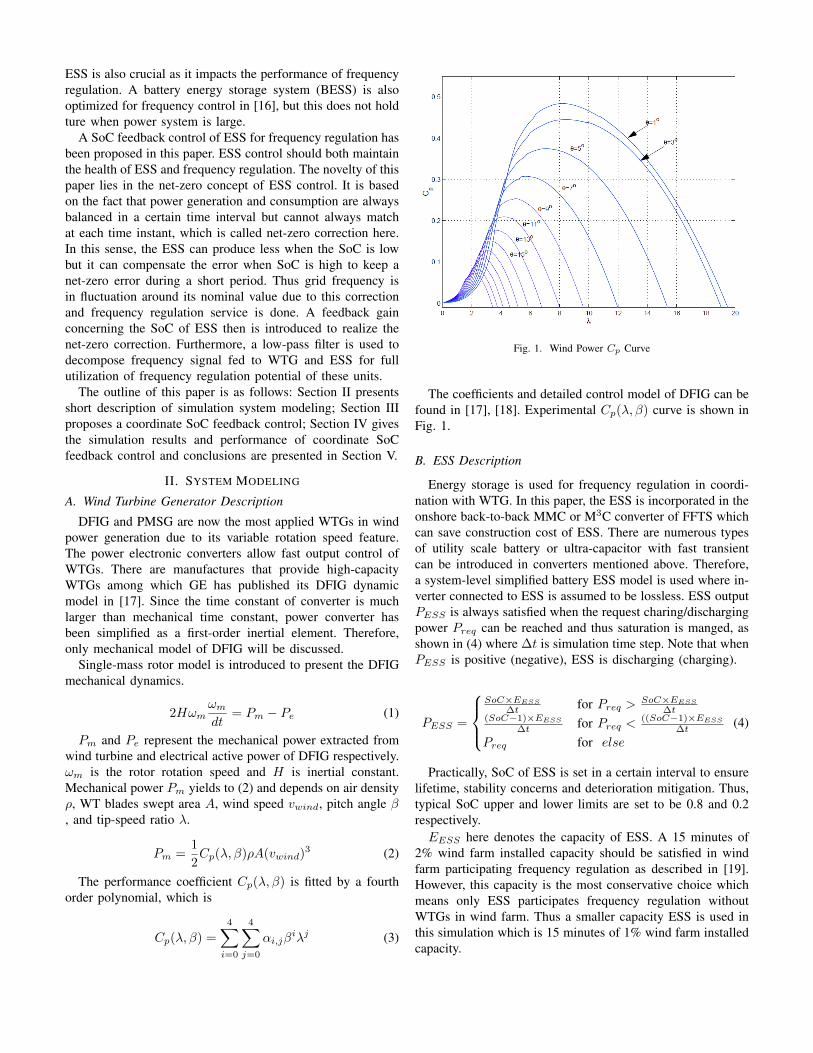
The performance coefficient Cp(λ, β) is fitted by a fourthorder polynomial, which is
Cp(λ, β) =
4∑i=0
4∑j=0
αi,jβiλj (3)
Fig. 1. Wind Power Cp Curve
The coefficients and detailed control model of DFIG can befound in [17], [18]. Experimental Cp(λ, β) curve is shown inFig. 1.
B. ESS Description
Energy storage is used for frequency regulation in coordi-nation with WTG. In this paper, the ESS is incorporated in theonshore back-to-back MMC or M3C converter of FFTS whichcan save construction cost of ESS. There are numerous typesof utility scale battery or ultra-capacitor with fast transientcan be introduced in converters mentioned above. Therefore,a system-level simplified battery ESS model is used where in-verter connected to ESS is assumed to be lossless. ESS outputPESS is always satisfied when the request charing/dischargingpower Preq can be reached and thus saturation is manged, asshown in (4) where ∆t is simulation time step. Note that whenPESS is positive (negative), ESS is discharging (charging).
PESS =
SoC×EESS
∆t for Preq >SoC×EESS
∆t(SoC−1)×EESS
∆t for Preq <((SoC−1)×EESS
∆t
Preq for else
(4)
Practically, SoC of ESS is set in a certain interval to ensurelifetime, stability concerns and deterioration mitigation. Thus,typical SoC upper and lower limits are set to be 0.8 and 0.2respectively.EESS here denotes the capacity of ESS. A 15 minutes of
2% wind farm installed capacity should be satisfied in windfarm participating frequency regulation as described in [19].However, this capacity is the most conservative choice whichmeans only ESS participates frequency regulation withoutWTGs in wind farm. Thus a smaller capacity ESS is used inthis simulation which is 15 minutes of 1% wind farm installedcapacity.

C. Load Description
Imbalance in generation and consumption leads to frequen-cy fluctuation. Therefore, the changing frequency can reflectssome load changing information. A typical frequency pattern[20] is presented in Fig. 2.
Fig. 2. Frequency Daily Pattern
Thus the power system load is defined in (5) where kL isstatic load-frequency coefficient and set to be 1.5. f and fNare measured and nominal grid frequency respectively.
∆PL = −kL(f − fN ) (5)
D. Simulation System Description
Classic Load-Frequency Control (LFC) is used in this paper.The structure of power system simulation model is depicted inFig. 3. It consists of conventional steam turbine, DFIG windfarm, ESS, load and power system model. DFIG wind farm,ESS and load has already been described above. Steam turbineis composed by governor model and reheat turbine model.R denotes the speed regulation parameter of the governorand TG is the mechanical governor response time. Kr, Trare steam turbine reheat constant and reheat time constantrespectively. Tt is the steam turbine time constant. Powersystem is represent by inertia constant H and load-dampingcoefficient D. The parameters of power system and steamturbine are given in Appendix.
Fig. 3. Power system simulation model block diagram
Low-pass filter is introduced to decompose the frequencysignal and high-frequency component ∆fhf is fed to ESS forthe fully utilization. Low-frequency component ∆flf is fed toDFIG for reduction in blade abrasion.
III. COORDINATE CONTROL STRATEGY
WTG should no longer operate in MPPT when it partic-ipates in frequency regulation service. Overspeed and pitchcontrol are most discussed deloading control method for WTGparticipation frequency regulation [12], [21]. However, over-speed cannot correctly function without pitch control whenwind speed is low so that coordinate control is necessary.As a result, this control method is implemented by DFIGdeloading control realized by pitch control and ESS SoCfeedback control.
A. DFIG Deloading Control
Pitch angle is considered to be smaller value in order toabstract more mechanical power from wind turbine. To deloadwind turbine, an additional angle is introduced to maintain acertain deloading coefficient kdel. The required pitch anglevalue is approximately linear to desired deloading power [21].A proportional gain is used to modify pitch angle θ respondto frequency deviation ∆f as emulation of droop control forsteam turbine. The complete deloading control block diagramis shown in Fig. 4. Tservo is the time constant of pitch bladeactuator.
Fig. 4. Pitch Angle Control for frequency regulation
B. SoC Feedback Control
Capacity of battery ESS is limited thus its operating con-dition can be critical, where the upper and lower bounds arepossibly reached. Practically, in order to expand the life ofESS, feedback control of ESS is introduced. As mentioned inSection II, the upper and lower limits are typically 0.8 and 0.2respectively. The convention is always set the reference SoCto be 0.5 [15], however, it will lessen cycling life of ESS andimpair the ESS performance since frequency deviation signalis independent of SoC.
In this paper, the adjustable reference SoC is implementedto fully utilize the battery ESS system. SoC reference valueSoCref yields to (6), when SoC exceed its bounds, a penaltyfunction in [22] is added to bring SoC into desired operationinterval.
SoCref =
0.8 for SoC > 0.85
0.5 for 0.15 < SoC < 0.85
0.2 for SoC < 0.15
(6)
The complete coordinate control scheme is depicted in Fig.5. DFIG wind farm responds to low-frequency component offrequency deviation and high-frequency component is fed to

ESS where the total power of DFIG and ESS is the output ofFFWPS. For the ESS control, An independent droop controlleris introduced to simulate governor 5% droop behavior. Also,it is noticed that there is a power error between desired andpractical ESS output.
Fig. 5. Coordinate control strategy of ESS and FFWPS
In long-term operation, the root mean square value ofthis power error, also called PRMSE, should be minimizedwith feedback gain chosen carefully. In addition, load andgeneration may not be the same at each time instant. However,its must be equalized in a certain period of time. AGC isused to fulfill this function. Thus, a net-zero production andconsumption is observed and net-zero of frequency deviation isachieved. Based on this concept, the optimization of PRMSEmeans the optimum control of wind farm participating fre-quency regulation.
IV. SIMULATION RESULTS
In this section, the proposed coordinate control scheme isverified in MATLAB/Simulink and Python, also the simulationresults are presented. An FFWPS without ESS for participatingfrequency regulation is used as benchmark to outline theeffectiveness of proposed control strategy.
A. Original Simulation System
A 594MW offshore wind farm is considered in this bench-mark system. It is composed by 165 GE 3.6MW DFIGsas discussed above. 4 days have been randomly selectedto represent the typical wind farm output during differentseasons. The wind farm output curve is shown in Fig. 6. Forthe simplicity of simulation, only the spring wind output isconsidered in the following cases.
Fig. 6. Wind farm output power (p.u.)
B. Benchmark System
The power system is set to have wind power penetrationas 20%, deloading factor kdel is 10% and the droop of windfarm is 5%. Detailed parameters is given in Appendix. Loadis described as Section II. Note that no ESS is implemented inthis system, thus low-pass filter is no longer needed. Then theFFWPS output without ESS for frequency regulation is shownin Fig. 7 . Pitch angle is shown in Fig. 8 in comparison ofMPPT mode.
Fig. 7. FFWPS output without ESS for frequency regulation
Fig. 8. DFIG pitch angle for frequency regulation
Obviously, by comparing Fig. 6 and Fig. 7,the powergeneration of wind farm is decreased due to deloading control.Fluctuation of wind farm is observed for the primary frequen-cy regulation. A 10% deloading is necessary for frequencyregulation. As described before, pitch control is applied forthe deloading and frequency regulation so that the pitchangle is frequently adjusted as shown in Fig. 8. Mechanicalabrasion may reduce the life of DFIG and introduce additionalmaintenance cost.
C. Test System
Incorporating ESS into FFWPS is beneficial to reducingmechanical abrasion and generation loss. Low-pass filter isimplemented for the ESS application. Chosen of time constantτ of this filter needs to be optimized and is not discussed here.In this simulation, τ = 15 min, and other parameters remainssame as benchmark system. Fig. 9 and Fig. 10 are the windfarm output power and pitch angle of DFIG. The ESS outputreference in this case is shown in Fig. 11.

Fig. 9. FFWPS output with ESS for frequency regulation
Fig. 10. DFIG pitch angle for frequency regulation
In this case, fluctuation of wind farm output is significant-ly reduced and pitch angle adjusting frequency is intenselydecreased. This is due to the low-frequency component offrequency deviation is fed to DFIG. It is noted that deloadingfactor is not necessary to be 10% due to less reserve demand,which shows economical benefits with less generation loss.
ESS desire ouput power is responding to high-frequencydeviation thus fast change is observed. Sizing of ESS can besimply decided as the maximum regulation power of ESS issatisfied. Note that this is the most conservative sizing criteria.
Fig. 11. ESS output power reference for frequency regulation
The SoC feedback control is implemented with feedbackgain α chosen as 0.5. The simulation result is shown in Fig.12. Pdroop is the reference power of ESS. A time intervalfrom 12h to 19h is investigated. SoC of ESS is maintained inthe desired bound and only small excursion is observed. The
Fig. 12. ESS output of SoC feedback control with α = 0.5
ESS is not available from 16h30 to 17h as PESS is nearlyzero. This may introduce financial penalty in the sense ofpower market. However, the revenue of more generation withless deloading may compensate or even exceed this penalty.The system frequency is compared and shown in Fig. 13, theeffectiveness is verified with small frequency deviation in SoCfeedback control system.
Fig. 13. System frequency
V. CONCLUSION
This paper has proposed a novel SoC feedback control ofESS for frequency regulation of FFTS with offshore windpower. Aggregate ESS is integrated in the onshore converterof back-to-back MMC or M3C, which saves the constructioncost of ESS. This strategy does not limited to the scaleof power system since no feedback control signal is fed toconventional steam turbine. Low-pass filter is introduced todecompose frequency deviation so that DFIG and ESS areable to react to different frequency component. Coordinatecontrol is implemented by simulation in MATLAB/Simulinkand python also effectiveness is verified. Future research isneeded for sizing of ESS and optimization of feedback gain.It is also a potential solution of wind farm/ESS hybrid controlfor frequency regulation when HVDC connection is used.
APPENDIX
a) Steam Turbine Parameters: Governor response timeconstant TG=0.2s, Steam turbine reheat constant Kr=0.5s,Steam turbine reheat time constant Tr=10.0s, Steam turbinetime constant Tt=0.3s, Governor speed regulation parameterR=3.125

b) Benchmark System Parameters: System inertia timeconstant M=10.0s, Load-frequency coefficient D=1, AGCproportional gain Kp,AGC=10.0s, AGC integration time con-stant Ti,AGC=20.661s
REFERENCES
[1] GWEC, “Global wind report 2016,” Global WindEnergy Council (GWEC), 2017. [Online]. Available:http://files.gwec.net/files/GWR2016.pdf?ref=Website
[2] X. Wang, “The fractional frequency transmission system,” in Proceed-ings of International Sessions in IEE Japan, 1994, pp. 53–58.
[3] X. Wang and X. Wang, “Feasibility study of fractional frequencytransmission system,” IEEE Transactions on Power Systems, vol. 11,no. 2, pp. 962–967, May 1996.
[4] S. Liu, X. Wang, L. Ning, B. Wang, M. Lu, and C. Shao, “Integratingoffshore wind power via fractional frequency transmission system,”IEEE Transactions on Power Delivery, vol. 32, no. 3, pp. 1253–1261,June 2017.
[5] X. Wang, X. Wei, and Y. Meng, “Experiment on grid-connection processof wind turbines in fractional frequency wind power system,” IEEETransactions on Energy Conversion, vol. 30, no. 1, pp. 22–31, March2015.
[6] G. Lalor, A. Mullane, and M. O’Malley, “Frequency control and windturbine technologies,” IEEE Transactions on Power Systems, vol. 20,no. 4, pp. 1905–1913, Nov 2005.
[7] R. Doherty, A. Mullane, G. Nolan, D. J. Burke, A. Bryson, andM. O’Malley, “An assessment of the impact of wind generation on sys-tem frequency control,” IEEE Transactions on Power Systems, vol. 25,no. 1, pp. 452–460, Feb 2010.
[8] G. Delille, B. Francois, and G. Malarange, “Dynamic frequency controlsupport by energy storage to reduce the impact of wind and solargeneration on isolated power system’s inertia,” IEEE Transactions onSustainable Energy, vol. 3, no. 4, pp. 931–939, Oct 2012.
[9] J. F. Conroy and R. Watson, “Frequency response capability of fullconverter wind turbine generators in comparison to conventional gener-ation,” IEEE Transactions on Power Systems, vol. 23, no. 2, pp. 649–656,May 2008.
[10] T. Kovaltchouk, V. Debusschere, S. Bacha, M. Fiacchini, and M. Alamir,“Assessment of the impact of frequency containment control andsynthetic inertia on intermittent energies generators integration,” inProc. Eleventh Int. Conf. Ecological Vehicles and Renewable Energies(EVER), Apr. 2016, pp. 1–8.
[11] F. Wilches-Bernal, J. H. Chow, and J. J. Sanchez-Gasca, “A fundamentalstudy of applying wind turbines for power system frequency control,”IEEE Transactions on Power Systems, vol. 31, no. 2, pp. 1496–1505,March 2016.
[12] Y. z. Sun, Z. s. Zhang, G. j. Li, and J. Lin, “Review on frequency controlof power systems with wind power penetration,” in 2010 InternationalConference on Power System Technology, Oct 2010, pp. 1–8.
[13] A. Mullane and M. O’Malley, “The inertial response of induction-machine-based wind turbines,” IEEE Transactions on Power Systems,vol. 20, no. 3, pp. 1496–1503, Aug 2005.
[14] S. Ghosh, S. Kamalasadan, N. Senroy, and J. Enslin, “Doubly fedinduction generator (dfig)-based wind farm control framework for pri-mary frequency and inertial response application,” IEEE Transactionson Power Systems, vol. 31, no. 3, pp. 1861–1871, May 2016.
[15] J. Dang, J. Seuss, L. Suneja, and R. G. Harley, “Soc feedback control forwind and ess hybrid power system frequency regulation,” IEEE Journalof Emerging and Selected Topics in Power Electronics, vol. 2, no. 1, pp.79–86, March 2014.
[16] P. Mercier, R. Cherkaoui, and A. Oudalov, “Optimizing a battery energystorage system for frequency control application in an isolated powersystem,” IEEE Transactions on Power Systems, vol. 24, no. 3, pp. 1469–1477, Aug 2009.
[17] N. W. Miller, J. J. Sanchez-Gasca, W. W. Price, and R. W. Delmerico,“Dynamic modeling of ge 1.5 and 3.6 mw wind turbine-generators forstability simulations,” in 2003 IEEE Power Engineering Society GeneralMeeting (IEEE Cat. No.03CH37491), vol. 3, July 2003, pp. 1977–1983Vol. 3.
[18] N. R. Ullah, T. Thiringer, and D. Karlsson, “Temporary primary fre-quency control support by variable speed wind turbines-potential andapplications,” IEEE Transactions on Power Systems, vol. 23, no. 2, pp.601–612, May 2008.
[19] E. N. On, “Germany grid code regulations for high and extra highvoltage,” Report ENENARHS2006, p. 46, 2006.
[20] RTE. (2017) Network frequency. [Online]. Available: https://clients.rte-france.com/lang/an/clients producteurs/vie/vie frequence.jsp
[21] E. Loukarakis, I. Margaris, and P. Moutis, “Frequency control supportand participation methods provided by wind generation,” in Proc. IEEEElectrical Power Energy Conf. (EPEC), Oct. 2009, pp. 1–6.
[22] X. Li, D. Hui, and X. Lai, “Battery energy storage station (bess)-based smoothing control of photovoltaic (pv) and wind power generationfluctuations,” IEEE Transactions on Sustainable Energy, vol. 4, no. 2,pp. 464–473, April 2013.