Embed Size (px)
DESCRIPTION
A novel 60 MW Pulsed Power System based on Capacitive Energy Storage for CERN PS machine. Jean-Paul BURNET CERN, European Organisation for Nuclear Research. Menu. Introduction PS power system Research of new solutions Novel power system with capacitive energy storage Introduction to POPS - PowerPoint PPT Presentation
Citation preview

Trieste (IT), 20 may 2008 POPCA
A novel 60 MW Pulsed Power System based on
Capacitive Energy Storagefor CERN PS machine
Jean-Paul BURNET
CERN, European Organisation for Nuclear Research

POPCA2
Menu
– Introduction– PS power system– Research of new solutions– Novel power system with capacitive energy storage– Introduction to POPS– Conclusions

POPCA3
The PS is in operation since 1959 The PS is part of the LHC injection
chain It is a cycling machine (1.2s) It is composed of 100 main magnets
The CERN accelerator network

POPCA4
PS machine
Cycle : 1.2s or 2.4s100 magnets: 0.95H, 0.32
1- Voltage : ± 9000V
2- Current : 0 to 5500 A
3- P = ± 40 MW with dP/dt = ± 1 MW/ms

POPCA5
PS power profileCycles
Low cycle: 14 GeV– 2.7 kA in 0.4s– Flat top: 0.3 s– Repetition: 1.2s
Heavy cycle: 26 GeV– 5.5 kA in 0.7s– Flat top: 0.4s – Repetition: 2.4s– Rotor speed 52-49 Hz
0A
5500A

POPCA6
Ratings
Load: 0.95 H / 0.32 DC output: 5.5 kA / 9 kVThyristor rectifiers, 197810 millions cycles per year!
PS actual main power system

POPCA7
Rotating machine
SIEMENS, 1968Generator: 90 MVAMotor: 6 MWSpeed: 1000 rpmRotors weight: 80 +10 T
PS actual main power system

POPCA8
Studies for new power system
Network solutions Storage system
– Mechanical storage– Inductive storage– Capacitive storage
Guideline– Suppress single point of failure– Modular approach with redundancy

POPCA9
Direct network connection on 400kV Many studies were done to study the connection of the rectifiers to the electrical
network. The ONLY solution was to:
– Connect the rectifiers via an 90 MVA transformer on the 400 kV EDF network– Install a reactive power compensator of 85 MVAR + 75 MVA of harmonic filters– Install an 18 kV power line between Prevessin and Meyrin (4 km)

POPCA10
Direct network connection on 400kV
Advantages– Use of “industrial” products (not off-the-shelf)– Good strategy for spare transformer and compensator with SPS powering
Drawbacks– Cost– Bandwidth response limited due to thyristor technology (2Q converter)– Far to be sure (the limit of this technology) to get a good voltage
stability at the load (10-5; need more studies)– More sensitive to storms
– Active power taken on the 400 kV (+/- 50 MW every 1.2 second)– (dedicated distribution)

POPCA11
SMES (Superconducting Magnet Energy storage) Use a SMES to store energy and to exchange it with the magnets Integration in SVC 18 kV or inside the power converter Energy stored must be very high to limit the variation of magnetic field 80 MJ to exchange 14 MJ with the magnets Study done by ITP Karlsruhe (DE)
Mag
netsAC
DC
DC
DC
DC link
SM
ESDC
DC
18 kV AC

POPCA12
SMES (Superconducting Magnet Energy storage) Advantages
– Compact solution– Easy to protect (short-circuit the SMES in case of problem)– Modular approach is possible– Certainly a very interesting solution in the future (higher energy and
technology maturation)
Drawbacks– SMES are under study, no industrial product for this level of energy– Stray field– SMES are current sources, need two stages of conversion to
supply the magnets (I-V and V-I)– Cryogenic infrastructure and maintenance (no cryogenic in PS)

POPCA13 SVC with capacitor energy storage
capacitive energy storage
First ideas
EL group proposal =>

POPCA14
• DC/DC converters transfer the power from the storage capacitors to the magnets.
• Four flying capacitors banks are not connected directly to the mains. They are charged via the magnets.
• Only two AC/DC converters (called chargers) are connected to the mains and supply the losses of the system.
Chargers
Flying capacitors
The magnet stored energy is exchanged with capacitors banksThe losses are taken on the network
New power system based on capacitive storage

POPCA15
The main losses of the system are the magnets losses. During a 26GeV cycle, the peak power of the losses is 10MW. The required energy to cover the losses is supplied by the mains. The power rating of each charger is therefore 5MW. The chargers are regulated in power with a reference that follows the magnets losses.
The maximum magnetic energy stored in the magnets is 12MJ for a 26GeV cycle. This energy is supplied by the capacitor banks.
Energy management

POPCA16
When the magnet current rises to 5.5kA, the capacitor bank voltage decreases from 5kV to 2kV. During the ramp down of the current, the capacitor bank voltage returns to 5kV
Energy management

POPCA17
The system is designed with a redundancy policy. If a capacitor bank, a DC/DC converter or a charger is in fault, the power system can still operate with the complete performance.
Operating with only one charger is the worst case as the input power will be limited to 5MW. However, by changing the charging profile, a 26GeV cycle can still be executed.
Energy management: redundancy

POPCA18
• DC converter ratings: 6kA / 5kV
• Standard industrial products: 2 kA / 5 kV from Medium Voltage Drive
• Solution: Three converters in parallel
By interleaving the firing pulses, the output filter is reduced and the bandwidth of the voltage loop is three times higher than the individual switching frequency
DC/DC converters

POPCA19
From studies to POPS project After an European tour of industry, we thought it was possible to build
such a power system DG approved the project end of 2006 Call for tender in 2007 Contract signature in December 2007 January 2008: Start of POPS project (POwer for PS)
Contractor CONVERTEAM (ex Alstom Power Conversion)– Main market: Marine, Oil&Gas, industries– Turnover: 700M€– Employees: 5000

POPCA20
POPS status schedule
– June 08: Design report approval– October 08: Civil engineering works– March 09: First delivery from Converteam– June 09: Installation– September 09: Start of commissioning– November 09: First test with magnets – April 2010: POPS in operation
Budget: 12 M€

POPCA21
POPS topology

POPCA22
Technologies DC converter topology
– Paralleling H-bridges– Output chokes – Current loop balance

POPCA23
Technologies Medium voltage Drives
– NPC converter– IEGT (Press pack IGBT)– Water cooled– Coupled choked

POPCA24
Technologies

POPCA25
Technologies Capacitor banks
– 5kV Dry capacitors– Polypropylene metalized self healing– Outdoor containers: 2.5m x 12m, 24 tons– 0.247F per bank, 126 cans– 1 DC fuse– 1 earthing switch

POPCA26
Technologies Redundancy
– Can work without one capacitor bank– Can work without one charger– Can work without one DC converter
POPCA27
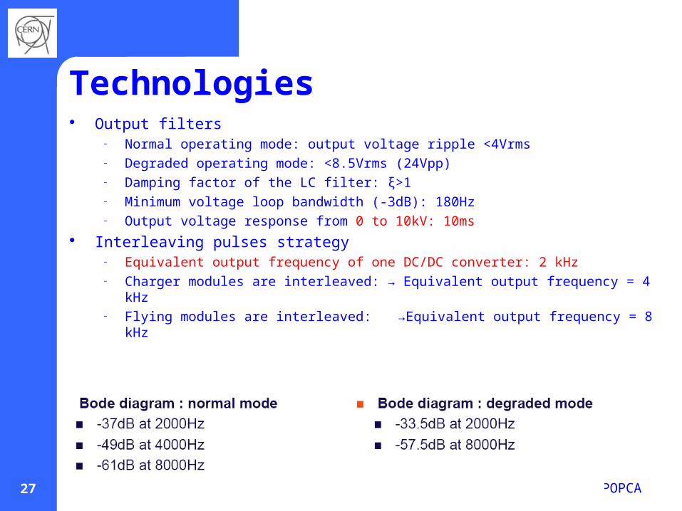
Technologies Output filters
– Normal operating mode: output voltage ripple <4Vrms– Degraded operating mode: <8.5Vrms (24Vpp)– Damping factor of the LC filter: ξ>1– Minimum voltage loop bandwidth (-3dB): 180Hz– Output voltage response from 0 to 10kV: 10ms
Interleaving pulses strategy– Equivalent output frequency of one DC/DC converter: 2 kHz– Charger modules are interleaved: → Equivalent output frequency = 4 kHz– Flying modules are interleaved: →Equivalent output frequency = 8 kHz

POPCA28
Technologies Output filters
– Leq = 3mH– CFx1 & 2 = 0.29mF– CFx = 1.5mF– Rfx = 2.24 Ω / 10kW

POPCA29
Technologies

POPCA30
POPS layout

POPCA31
POPS layout
POPS – Etat de la maquette au 5 Mai 2008
PROJET POPS
Bat.367 (existant)
Extension 367(existant)

POPCA32
• The main advantages of this solution are:• the integration of the storage elements
in the power converter topology • the modularity of the system with redundancy • the use of standard products from the medium voltage drive market
• This innovative solution has a real interest for physics laboratories and for all applications requiring rapid exchange of active power
• POPS is planned for operation in 2010
• The main difficulty was to convince industry to follow us
PatentThe global system with dedicated control has been filed as a patent
application. European Patent Office, Appl. Nr: 06012385.8
Conclusions

POPCA33
Thank you for your attention