Embed Size (px)
Citation preview

NRL Report 6254
A Nonreciprocal Circular Polarizer
M. L Rn ss
A/irrouwir Antennas and Comptments Hranrh Electronics Dnnsum
June 17. 1965
COPY 0F_r-^^ I/T^COPY %. f.M
MiÜiüilCHE $. ÖJd)
DDC eacana nrpr? AUG2 1965 I
DOC-IRA E
VS. NAVAL RESEARCH LABORATORY Washington. D.C.
MfflHlifflf

I
CONTENTS
Abstract Problem Status Authorization
INTRODUCTION
GENERAL PRINCIPLES
DESCRIPTION
EXPERIMENTAL PROCEDURE
EXPERIMENTAL RESULTS
Model 1 Model 2
APPLICATIONS
Antenna Systems Circulator
CONCLUSIONS
ACKNOWLEDGMENT
ü U 11
1
1
2
3
4
4 5
6
6 8
8
9
V

ABSTRACT
A nonreciprocal circular polarizer has been developed. This ferrite device converts linear polarization propagating in rectan- gular waveguide into circular polarization propagating in circular waveguide. The sense, right- or left-hand, of the circular polariza- tion is determined by the direction of a magnetic field applied to the ferrite. If one sense of circular polarization, e.g.. right-hand, is transmitted, then only left-hand circular polar izat ion can be received.
Performance data indicate good ellipticity with reasonable loss and VSWR for two models of the circular polarizer, and for two devices - a circulator and a nonreciprocal antenna element - based on the polarizer. The antenna element permits one antenna to be used both to transmit and to receive the reflected circularly polarized signals from a target.
PROBLEM STATUS
This is an interim report; work continues on other phases of the problem.
AUTHORIZATION
NRL Problem R08-36 BuShips Project SR 008-03-02-9637
Manuscript submitted February 10, 1965.
11

A NCNRECIPROCAI, CIRCULAR POLARIZER
INTRODUCTION
The use of circular polarization at microwave frequencies is dependent upon a device to convert the wave produced by the signal source (klystron, magnetron, etc.) into a cir- cularly polarized wave. Several techniques are available which can be used to produce reciprocal transmission-line components that convert linear polarization into circular polarization. There are applications, however, in which it is desired that the component be nonreciprocal. One application for such a polarizer is in a radar system where it is necessary to transmit one sense of circular polarization and to receive the opposite sense of circular polarization. Another application may be found in the construction of a three- port circulator.
Recently, as the outgrowth of a ferrite phase-shifter study by the author, a method for designing a nonreciprocal polarizer was obtained. A section of rectangular waveguide is joined to a section of circular waveguide in such a way that the two have a common longitudinal axis. A ferrite rod of suitable diameter and length is placed along the axis of the rectangular waveguide, with one end protruding into the circular waveguide. A longitudinal magnetic field of appropriate magnitude is then applied to the ferrite rod. If a linearly polarized wave is introduced into the rectangular waveguide, the wave trans- mitted into the circular waveguide will be circularly polarized, the sense of polarization depending on the direction of the applied magnetic field. A circularly polarized wave of the opposite sense can be transmitted from the circular to the rectangular waveguide, where it is converted to a linearly polarized wave. However, a circularly polarized wave of the same sense will be completely reflected by the rectangular waveguide section. Two models of the circular polarizer were investigated, and the data obtained from these models are presented in this report. The principal quantities studied (ellipticity. VSWR. and insertion loss) are shown as u function of applied magnetic field and of frequency. Additional information is then presented for the two applications previously mentioned.
GENERAL PRINCIPLES
The development of this polarizing device is an outgrowth of a study of the DOFL or Reggia-Spencer phase shifter, which consists of a ferrite rod located along the axis of a rectangular waveguide. A biasing magnetic field is also applied along this axis. Several theoriest have been advanced to explain the operation of this phase shifter. Each of these theories presents the view that the linearly polarized wave in the rectangular waveguide is converted to circular or elliptical polarization in the ferrite-loaded region and then converted back to linear polarization on leaving the ferrite-loaded region. The presence *F. Regula and E.G.Spencer, "A New Technique in Ferrite Phase Shifting for Beam Scan-
ning of Microwave Antennas," Proc. IRE 45:1510-1517 (Nov 1951 )
fP.A. Rizzi, B. Gatlin, " Rectangular Guide Ferrite Phase Shifters Employing Longitudinal Magnetic Fields," Proc. IRE 47:446-447 (Mar 1959).
J.A. Weiss, "A Phenomenological Theory of the Reggia-Spencer Phase Shifter," Proc. IRE 47:1130-1137 (June 1959).
During the study of the circular polarizer, an inte resting extension of Weiss' work by Dr. Ernst Neckenburger was noted. The reference is as follows: "Zur Wellenausbrest- ung an einem langsmagnetisse rten Fe rritstab inelektrisch anisot ropt r Umgeburg," Zeit- schrift fur angewante Physik 14(5:282-208 (1962).

2 NAVAL RESEARCH LABORATORY
of elliptical polarization in the ferrite-loaded region suggested the possibility of convert- ing this phase shifter into a nonreciprocal circular polarizer.
According to the theory of Weiss,* if a ferrite rod is chosen with diameter of correct size to support the DOFL mode, this ferrite rod in rectangular waveguide can support only a single elliptically polarized mode whose ellipticity is dependent on the applied magnetic field. Both the ratio of major to minor axis of the polarization ellipse (ellip- ticity) and the sense of polarization (positive or negative rotation of the electric vector with time) are determined by the direction and magnitude of this axial magnetic field.
The basic change in the phase-shifter geometry which converts it to a circular polarizer Is that, after the elliptically polarized mode is established in the ferrite-loaded rectangular waveguide, the waveguide cross section is changed to a circular cross section capable of propagating elliptical polarization even in the absence of the magnetized ferrite rod. The ferrite rod passes through the junction of the two waveguides and. since the energy Is closely bound to the ferrite rod, the effect of the discontinuity is minimized. A taper is provided to minimize the effects of the transition from ferrite-loaded to standard waveguide. By proper choice of both frequency and magnetic field, circular polarization can be obtained; however, as might be expected, the purity of this circular polarization is sensitive to both of these quantities. This sensitivity can be considerably reduced by inserting a small-diameter circular waveguide between the rectangular waveguide and the larger diameter circular waveguide and extending the ferrite rod through the smaller diameter circular waveguide into the larger one.
It is well known that if a circular waveguide contains a longitudinally magnetized ferrl»e rod located along the waveguide axis, the phase velocities of right- and left-hand circularly polarized waves are different. Moreover, parameters can be chosen so that one sense of circular polarization Is cut off. whereas the other sense is free to propagate. In this case, since the diameter of the ferrite rod and the frequency have been determined, the cutoff condition is obtained by reducing the size of the circular waveguide. Inasmuch as the cutoff phenomenon is obtained over a relatively large range of frequency and magnetic-field values, the use of such a cutoff section to attenuate the unwanted sense of circular polarization decreases the dependence of ellipticity on both frequency and applied magnetic fields.
Now consider a hypothesis explaining the action of the cutoff section. Elliptical polari- zation is produced in the rectangular waveguide section containing the ferrite rod. Upon encountering the magnetized cutoff sectioti, one of the circularly polarized components composing the elliptical polarization is reflected, while the second sense of circular polarization continues through the cutoff section. The efficiency of this cutoff, or filter, section depends primarily on the diameter of this section. Operation well below the cut- off frequency for the cross polarized mode, but still in the reasonable wall loss region of the transmitted mode, is required.
DESCRIPTION
The first, and simplest, model of the circular polarizer consists of a rectangular waveguide (RG 52/U) butted onto a circular waveguide (0.9375 In. I.D.) with a tapered ferrite rod extending Into each waveguide. A solenoid enclosing the region containing the ferrite rod provides a magnetic field directed along the common axes of the ferrite rod and waveguides. The waveguide assembly is shown in Fig. la along with the dimensions of the circular polarizer tested. These dimensions were determined from a study, con- ducted at 9.375 kMc/sec, of diameter, length, and position of the ferrite rod.
♦J.A. Wei«s, "A Phenomenological Theory of the Reggia-Spencer Phase Shifter,' Proc, IRE 47:1130-1137 (June 1959).

NAVAL RESEARCH LABORATORY
CIRCULAR KAVEGUIOE
APPLIED MAGNETIC FIELD
0 9375 IN OIA
RECTANGULAR WAVEGUIDE
04 IN
MODEL I
CIRCULAR WAVEGUIDE
09 IN
RECTANGULAR WAVEGUIDE
FERRITE ROD 0.270 IN. DIA. « 3 IN. LONG PLUS t IN. TAPERS, 5 IN. TOTAL. ROD BODY PROTRUDES 0.4 IN. INTO LARGE DIAMETER CIRCULAR WAVEGUIDE. SMALL DIAMETER WAVE- GUIDE 0.4 IN. DIA. ' 1 IN. LONG.
SMALL OlA CIRCULAR WAVEGUIDE
MODEL 2
FERRiTE ROD
(b)
Fig. 1 - The circular polarizer, models 1 and 2
In the second model, a section of reduced-diameter circular waveguide was placed between the rectangular and 0.9375-in.-diameter circular waveguide. As was previously mentioned, the purpose of this smaller diameter waveguide section is to reduce the mag- netic-field and frequency sensitivity of the transmitted elliptically polarized wave by excluding the unwanted circularly polarized component. This polarizer, consisting of a ferrite rod mounted along the common axis of three sections of waveguide, is shown in Fig. lb, along with the dimensions of its various components. A magnetic field is applied along this same axis. These dimensions were selected from a preliminary study in which the ferrite-rod diameter, the ferrite-rod length, the cutoff-section length, the cutoff- section diameter, and ferrite-rod position were treated as the variable parameters.
EXPERIMENTAL PROCEDURE
Ellipticity, insertion loss, and VSWR were measured at several applied magnetic-field values and over a band of frequencies. The ellipticity was measured in circular waveguide by use of a rotating probe located before a matched waveguide load. In this study, the ellipticity is given in decibels and is the difference between the maximum and minimum readings obtained during one revolution of the probe. Pure circular polarization would thus have an ellipticity of 0 db, while good ellipticity will refer to an ellipticity between 0 and 1 db, which corresponds to an isolation or difference of 24.8 db or greater between the two circularly polarized waves composing the elliptical mode. Both the insertion loss and VSWR were measured using a ratiometer. The insertion loss of the circular polariza- tion was measured by adding a quarter-wave plate and a two-mode transducer to the circu- lar waveguide output, so that standard rectangular waveguide detectors could be used. The quarter-wave plate was oriented so that one sense of circular polarization would exit at one port of the two-mode transducer, while the opposite sense would exit at the second port.
4 NAVAL IESIAICH LAIOIATORY
16r:,-----------------,5 ~ 14 I
'D , ;:: f .... u ~ 4 ~
w 2
I I
I
/ /
/
,... /
/ ---- ELLIPT ICI TY ---vswR · ··· · ···INSERTION LOSS FO
THE PRINCIPA L CIRCUL ARLY POLAR · IZED MO
Fi g . 2 - Elliptici ty, 1 o s s , and VSWR depe ndence on applied m agnetic field for the model 1 p olarize r , fr e quency 9 . 3 7 5 k Me Is e c
EXPERIMENTAL RESULTS
Model 1
Data obtained from the study of the first model (Fig. la) of the circular polarizer are presented in Figs. 2 and 3. In Fig. 2 the effect of varying the applied magnetic field on the ellipticity, insertion loss, and VSWR is noted for this configuration, which utilizes a tapered three-inch-long, 0.270-in.-diameter ferrite rod. As the applied magnetic field increases, the ellipticity decreases from its high initial value , reaching a minimum value of 1/ 2 db at approximately 16 oersteds, and then increases. The VSWR of this model has a general tendency to increase slowly to a maximum value in the vicinity of 160 oersteds , which is a magnetic-field value greater than would be used in practice due to the high value of the ellipticity present for these field values. An experimental polarizer was built to operate at 9.375 kMc/ sec using an applied magnetic field of 16 oersteds. The ellipticity was on the order of 1/ 2 db, the VSWR approximately 1.3 , and the insertion loss around 0. 6 db.
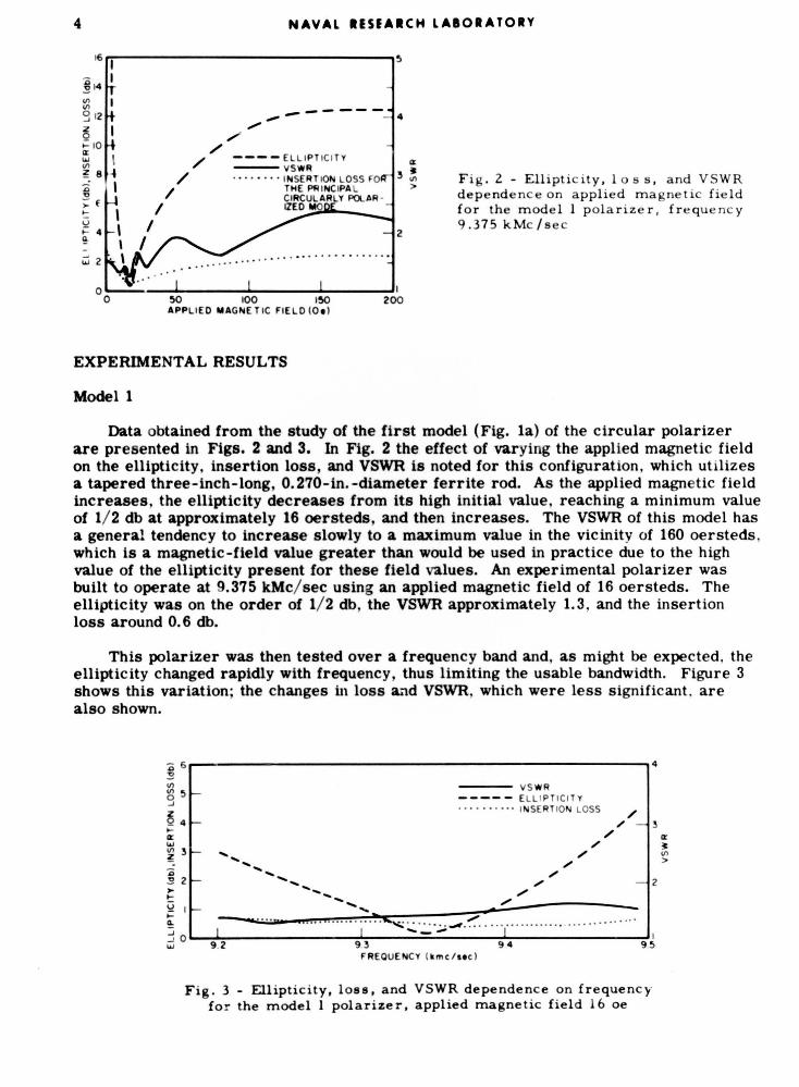
This polarizer was then tested over a frequency band and, as might be expected, the ellipticity changed rapidly with frequency , thus limiting the usable bandwidth. Figure 3 shows this variation; the changes in loss a.,d VSWR, which were less significant. are also shown.
'D 6~--------------------------~4 ~ Ul Ul 5 g
~ 4 .... a:: .... ~ 3
'D ~ 2 ,. 1-
............... ........ ....... -...........
--- VS WR ----- ELLI PTICI TY • • • • · • · • • • INSERT ION LOSS
/ /
/ /
/ /
/
/ /
/
Q 1 a
:i: .... , : ... :: ...... .... '!' .~ . . ... .. . """" ·~· ·· ·· · · · ·· ·· ·· · · · ···· ··· · · · · · · · 3o~~~------~~---~-~----~~-------~.1 .... 9 .2 9.3 94 95
FREQUENCY ( km c/ .. c)
Fig . 3 - Ellipticity, loss, and VSWR dependenc e on frequency for the model 1 polarizer, applied magnetic field 16 oe
a:: 31 Ul >

4 <; ~ IJ)
"' 0 ...J
3 z 2 a: .... IJ)
~
NAVAl IUEAICH lAIOIATOIY
5 r--------,--------------------------------------------------~
<;4 s IJ) IJ) 0 ...J
>f.-
~ f.c..
I I I \ \ \ \ \ \
- - -- S WR · - · - · - ELLI PT ICI TY - --- LOSS
F ig. 4 - Ellipticity , loss, and VSWR dependence on applied magnetic field for the model Z polarizer, frequency 9.375 kMc/sec
- ---- VS WR · - · - · - · - ELLIPTICI TY ------- I NSE RTION L OSS
a: ~ IJ)
>
5
....: /
/ / .,
~ ,.. f.-u ;: <l. :::; ...J ....
0
/ / ' / ...... "" ' / -·-' ' / -· ' ' / - ·-· ., ....... ._ .__..,._ .- ·
· - . :::.~- ·- ·- ·- ·- ·- ·- ·----~----------~------------~------~-~--~-------~------------_. ____________ ~------~10 93 94 95
FREQUENCY ( kmc/sec)
Fig . 5 -Ellipticity , loss , and VSWR dependence on frequency for the model 2 polarizer, applied magnetic field 65 oe
a: ~ IJ)
>
Model 2
Consider the model of the polarizer in which a "cutoff" section of small-diameter waveguide is employed as previously shown in Fig. lb. The data obtained by measurements ofthis polarizer with a l-in. -long cutoff section are presented in Figs. 4 and 5. Figure 4 depicts the effect of the applied magnetic field on VSWR, loss, and ellipticity at 9.375 kMc/ sec. Inspection of the VSWR curve shows that initially most of the power is reflected. *
*The c utoff section can be used between two rectangular waveguide sections in o rder to form a waveguide switc h .
A . Clavin, "Rectangular Waveguide Switches , .. IRE Trans. on Mic rowave Theory & Techs., M TT -9:365-366 (July 1961 ).

6 NAVAL tISEARCH LABORATORY
After the magnetic field reaches 30 to 40 oersteds, sufficient power is transmitted to permit measurement of the ellipticity, since the VSWR has decreased to a more reason- able level. The ellipticity changes very slowly for values of magnetic field that permit propagation. At this frequency, a polarizer with reasonable loss, good ellipticity, and good VSWR can be constructed.
Next (Fig. 5) consider the loss, ellipticity, and VSWR dependence on frequency when the macnetic field is maintained at 65 oersteds. The usable frequency range of this model polarizer is limited by very rapid increase of loss and VSWR, as compared with the simplified model, in which ellipticity is the limiting factor. No attempts were made to increase the bandwidth of this device.
Now consider the effects of varying two of the other polarizer parameters: the length of the "cutoff" waveguide and the ferrite rod length. Cutoff waveguide sections of three different lengths, 3/4, 1, and 1-1/4 in., and the same 0.4-in. diameter, were used with three-inch-long, 0.270-in.-diameter ferrite rods. The best ellipticity was obtained when the longer cutoff sections were used; however, there was a small increase in the insertion loss when the longest section was used.
It is of interest to note that by adjusting the value of the biasing magnetic field, the operating region of the polarizer can be changed without significantly altering the purity of the resultant circularly polarized waves. Studies were also made with different length (1.5 to 3 in.) ferrite rods used with a one-inch-long cutoff section. Essentially the same degree of purity of circular polarization was obtained from each of the rods; however, the insertion loss was lowest for the shortest rod.
APPLICATIONS
Antenna Systems
The property of the circular polarizer of transmitting one sense of circular polari- zation and receiving the opposite sense immediately suggests the use of this device as an antenna element. A circularly polarized signal reflected from most typical targets has predominantly the opposite sense of circular polarization from the transmitted signal. Hence if the same antenna is to be used both to transmit and receive, either a dual- polarization antenna or feed system is required. The obvious adaptation of this polarizer to a radiating element is obtained by placing a conical horn after the polarizer. In another modification used to convert the polarizer into an antenna element, the ferrite rod pro- jected from the cutoff section directly into free space (Fig. 6).
Far-field radiation patterns were measured for each of the two circularly polarized elements by use of a rotating linearly polarized receiving horn located in the far field of the antenna. This rotating horn will show any variations in the ellipticity of the radiated wave as the circularly polarized transmitting antenna is rotated in azimuth. The radia- tion patterns of the horn-polarizer combination are determined by the conical horn. The principal effect of the polarizer is to determine the on-axis ellipticity.
In Fig. 7, radiation patterns are shown for the rod-polarizer illustrated in Fig. 6b. For a given angle, the ellipticity can be determined by taking the difference between the maximum and minimum values, i.e., the height of the shaded area in decibels. For example, the ellipticity at 0 degrees is approximately 1/2 db, while at 3 db down from the maximum power the ellipticity is on the order of 1 db. Patterns were also measured using a circularly polarized receiver. The sense of the circular polarization of this antenna is controlled by the direction of the applied magnetic field and, if the wave incident on the antenna is cross polarized, it is reflected. If a plane wave circularly polarized in the opposite sense to that which is radiated is incident on the antenna, the receive pattern

NAVAL RESEAICH LABORATORY
6a CIRCULAR POLARIZER MORN
COMBINATION
6b ROD RADIATOR
Fig. 6 - Nonreciprocal circular polarizer antenna elements
AZMUTM ANGLE (OECREESi
Fig. 7 - Nonreciprocal antenna radiation patterns, frequency 9.375 kMc/sec

NAVAL RESEARCH LABORATORY
PORT |i*0 I
^^O] P0RT HO 2
APPLIED MA&NETiC FIELD
TYKO MODE TRANSDUCER
PORT NO
Fig. 8 - Circulator using a model 2 circular polarizer
is essentially the same as the transmitting pattern. Unfortunately, if several elements of this type are used in a linear array, there is relatively strong coupling between elements; thus the ellipticity of the array is poorer than that of a single element. It is felt that a modification of this element would be necessary for use in a linear array composed of circular polarizer elements. The bandwidth of the polarizer radiating into free space is somewhat greater than the polarizer-horn combination but is still limited by the VSWR.
Circulator
A three-port, reflection-type circulator may be formed by adding a two-mode trans- ducer and quarter-wave plate to the circular polarizer as shown in Fig. 8, where the cut- off polarizer is shown. The operation of this circulator may be understood by following a linearly polarized wave entering the different ports. A wave entering port 1 of the trans- ducer is converted to a sense of circular polarization that will not propagate in the polarize;, This wave is reflected and exits at port 2, the second transducer port. A wave entering the second port is converted to the sense of circular polarization that will propagate through the polarizer and exits at port 3 (the polarizer rectangular waveguide port). If a wave is fed into port 3, it exits at port 1 of the two-mode transducer. The circulator action is thus complete.
The second model polarizer (Fig. lb) was combined with a quarter-wave plate and two-mode transducer to produce a circulator. Typical data obtained from this circulator are shown in Fig. 9. In designations such as *l-2" shown in Fig. 9. the input port is represented by the first digit and the output port by the second digit. From these data it is readily noted that the transmission loss is least when the transmitted wave is reflected by the polarizer rather than passing through this device. The VSWR of ports 1 and 2 iS determined by the ellipticity of the circular polarization produced by the quarter waveplate and by the polarizer. The isolation between ports 1 and 2 is principally determined by the ellipticity of the waves produced by the polarizer and the quarter waveplate; high elliptic- ity produces poor isolation. Circularly polarized waves reflected from the polarizer strongly affect the isolation between ports 1 and 3. As with other types of ferrite circu- lators, reversing the magnetic field reverses the direction of circulation of power, and thus the circulator may be used as a switch.
CONCLUSIONS
A nonreciprocal, circularly polarizing device to convert linear polarization in rectan- gular waveguide into circular polarization in circular waveguide has been developed. Right-

NAVAL RESEARCH LABORATORY
94 FREOUCNCY (time/MC)
95 95 95 95
(P» ,f 10 BlAN«)
FREOUENCT (kmc/»«cl 'RlOulHCi («mc/itcl
Fig. 9 - Insertion loss, reflected power, and isolation dependence on frequency for each input of a circulator usingamodelZ circular polarizei
or left-hand circular polarization having an ellipticity of 1/2 db or less can be obtained at X-band from incident linear polarization. Since normally the reflected signal comes back in the opposite sense of circular polarization, the same antenna may be used for transmission and reception. Rapid electronic switching from one sense of circular polarization to the other sense is possible by changing the direction of the applied mag- netic field. This switching feature might be quite useful for changing polarization when there is interference with one sense of circular polarization. With the addition of readily available microwave components, the polarizer can be used to form a three-port circulator.
The results obtained in this study are by no means considered to be the optimum. With further work it would doubtless be possible to:
1. Increase the bandwidth
2. Decrease the forward coupling between elements when used in an antenna array
3. Improve the power-handling capacity.
ACKNOWLEDGMENT
The continuous guidance and encouragement of Dr. M.L. Kales of the U.S. Naval Research Laboratory is respectfully acknowledged.