Embed Size (px)
Citation preview
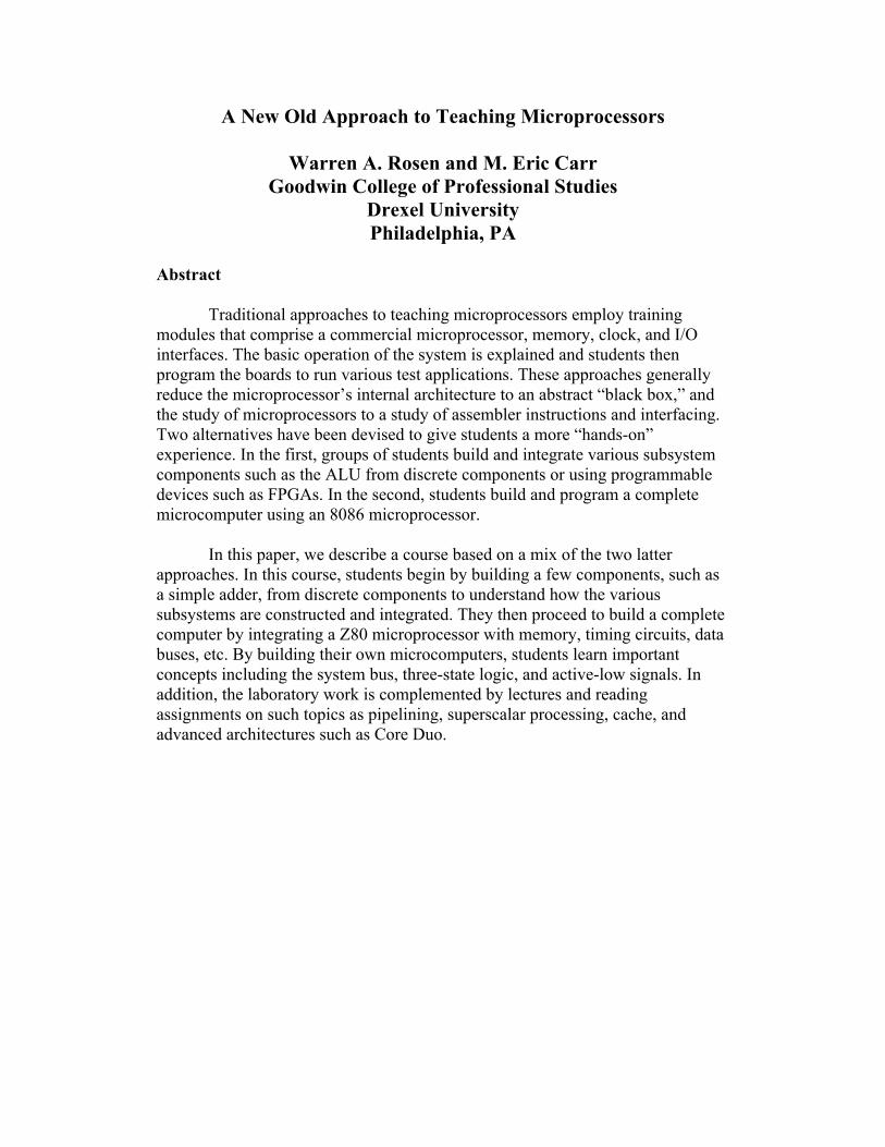
A New Old Approach to Teaching Microprocessors
Warren A. Rosen and M. Eric Carr Goodwin College of Professional Studies
Drexel University Philadelphia, PA
Abstract
Traditional approaches to teaching microprocessors employ training modules that comprise a commercial microprocessor, memory, clock, and I/O interfaces. The basic operation of the system is explained and students then program the boards to run various test applications. These approaches generally reduce the microprocessor’s internal architecture to an abstract “black box,” and the study of microprocessors to a study of assembler instructions and interfacing. Two alternatives have been devised to give students a more “hands-on” experience. In the first, groups of students build and integrate various subsystem components such as the ALU from discrete components or using programmable devices such as FPGAs. In the second, students build and program a complete microcomputer using an 8086 microprocessor.
In this paper, we describe a course based on a mix of the two latter approaches. In this course, students begin by building a few components, such as a simple adder, from discrete components to understand how the various subsystems are constructed and integrated. They then proceed to build a complete computer by integrating a Z80 microprocessor with memory, timing circuits, data buses, etc. By building their own microcomputers, students learn important concepts including the system bus, three-state logic, and active-low signals. In addition, the laboratory work is complemented by lectures and reading assignments on such topics as pipelining, superscalar processing, cache, and advanced architectures such as Core Duo.
Introduction
Historically, early courses in microprocessors were based on simple training kits using processors such as the 6800 or 8085 connected to system components such as memory, clock, etc.1 In these courses, the internal architecture as well as the remaining system components and interconnects (memory, clocks, buses, etc.) were described conceptually and the emphasis, in terms of the hardware usage, was on learning and using the instruction set and interfacing peripheral devices. Since those early times, microprocessor technology has progressed to the point that a trainer employing a Pentium or Core 2 device would essentially comprise a stand-alone computer. This leaves the instructor with the choice of either using a simpler trainer or using the students’ laptop or desktop itself as the trainer and teaching an extremely complex instruction set. In either case, the microprocessor’s internal architecture and external interconnects are reduced to abstractions and the study of microprocessors to a study of assembler instructions and interfacing. A third approach, intended to give the students a more “hands-on” experience, involves the students constructing a complete system from discrete building blocks or programmable components such as FPGAs.
In 2000, Jeon described a course in which each student constructed and programmed an 8086-based microcomputer.2 This approach eliminates many of the “black box” aspects of the conventional microprocessor course and gives the students some of the hands-on experience of the third approach.
In this paper, we describe a new course that combines many aspects and advantages of the older approaches described above. As such it constitutes a “new old” approach to teaching microprocessors. In this course the students begin by constructing several of the internal components of the CPU, such as a two-bit adder and two’s complement engine, to gain hands-on understanding of these components. Next, each student constructs a simple memory bus using three-state drivers. Finally, the students construct simple clock and control circuits and add the microprocessor to form a complete microcomputer system. A Z80 was selected for the CPU rather than an 8086 for several reasons. First and foremost, the 8086 is no longer manufactured. Second, the Z80’s clock is DC-coupled, allowing students to single-step through instructions for debugging (the 8086 requires a 2 MHz minimum clock speed). Third, the Z80 is a popular processor among hobbyists and is supported by a rich set of peripheral interface components and projects. Fourth, the Z80 provides completely independent data and address buses; on the 8086, the lower eight bits of the address bus are multiplexed with the data bus, which students can find confusing. In addition, since the Z80 is based on the 8080, Z80 instructions are very similar to basic x86 instructions. As an added benefit, the memory addressing on the Z80 is much simpler than x86-family addressing; the Z80 uses a flat memory model as opposed to the more confusing segment-plus-offset model used by x86 architecture CPUs.
In the next section, we describe the course objectives, followed by a description of the microcomputer construction and course content.

Course Objectives and Content
The Drexel Applied Engineering Technology Program offers the introductory microprocessor course in a 10-week quarter format. The course is required for students in the Electrical Engineering Technology concentration. The objectives of the course are to:
1. Explain basic microprocessor and microcomputer architectures 2. Explain the programming model and instruction set architecture of modern
microprocessors 3. build and program a simple microcomputer system 4. Interface basic I/O components to a microcomputer 5. Understand advanced microprocessor concepts such as pipelining, superscalar
processing, and the Core 2 architecture.
These objectives are achieved through a combination of lectures, outside (primarily web-based) reading assignments, hands-on laboratory exercises, and the construction of a Z80-based microcomputer. Table 1 shows the course topics by week. The course begins with a conventional introduction to microprocessors, including such topics as history of microprocessors, internal architecture, and common microprocessor families.
At the first class meeting, the students are given a detailed list of the components needed
to build the microcomputer together with potential suppliers. During the second week, the Z80 and Pentium architectures and programming models are presented and compared. Students also perform a lab exercise in which they construct a simple two-bit adder with carry and a 2’s complement engine in order to understand the basic operation of the ALU. During the third week, the Z80 instruction set and addressing modes are introduced. The lab exercises comprise a set of exercises performed on the students’ own laptop or desktop using the DOS debug program to poll and modify the contents of the x86 registers. The fourth and fifth weeks are devoted to such topics as memory types and three-state logic and data buses. Subsequent weeks are devoted to more advanced topics such as pipelining, superscalar processing, and the Core 2 architecture as the fabrication of the microcomputer progresses. Rather than using a standard textbook, a series of web-based reading assignments are given using such sites as Ars Technica.3
At the same time, the development of the microcomputer begins with the fabrication and
debugging of the programming unit and memory bus, as described in the next section. The key component of the course is the construction of this microcomputer.

Week 1 Introduction to microprocessors, history, generic
architecture, common microprocessor families, number systems
Week 2 Z80 architecture, Pentium architecture, Z80 and x86 programming models, instruction set architectures, RISC and CISC systems
Week 3 Z80 instruction set, Z80 addressing modes Week 4 Memory types, Z80 memory map, three-state logic
and data buses, Z80 bus timing Week 5 More Z80 instructions Week 6 Pipelining, more Z80 instructions Week 7 Superscalar processing Week 8 Core 2 architecture Week 9 Microcomputer completion and debug Week 10 Microcomputer debug
Table 1. Course topics by week.
Microcomputer Construction, Programming, and Operation
As noted above, the key element of the microprocessor course is the construction, by
each student, of a working Z80-based microcomputer. The computer, known as the “DrACo/Z80” for “DRexel Assembly COmputer / Z80” (named after the Drexel Dragons), is minimalist in design: a Z80 CPU, a 32kB SRAM chip for memory, and basic input and output devices, in the form of rotary hex switches for inputs and LEDs for outputs. CMOS-based Z80C00xx CPUs are still in production and popular among many hobbyists. These parts feature a true DC-coupled clock, allowing them to be run at arbitrarily slow clock speeds. This capability greatly simplifies the design, since single-stepping the system through instructions is simply a matter of providing a debounced clock signal.
Early in the course, we not only describe to the students the computer that they will be
building, we show them a working model to pique their interest (see Figure 1.) Once they see the Z80 computer in action, we describe its overall architecture at the subsystem level. Part of this process also involves demonstrating how the computer is programmed (in machine code, expressed in hexadecimal).
The prototype DrACo/Z80 consists of:
• A Z84C0010 CPU (in the top left corner of the board); • A Cypress CY7C199P 32kB static RAM chip; • 74LS245 buffer/line driver chips for input and output circuits; • Output LEDs for data (green) and address (blue); • Controls for single-step, auto/manual clock, run/program, write data, and reset; • Rotary hex switches for entry of data byte and address word;

• Dual bus headers (student boards have one header only); • Pull-down bus resistors (470-ohm for LEDs; 1k for logic); • A 555 astable oscillator circuit and 74LS76 flip-flop for a clock; • Various 74LS-series chips for glue logic.
Figure 1. The prototype DrACo/Z80 computer. In addition to the benefits described above, the Z80-based design proved to be simpler
and significantly less expensive to construct. Since it uses a single power supply and single-phase clock, the power and clock subsystems are simpler than those of an 8086-based system. Also, since the Z80’s address and data buses do not share any pins, no demultiplexing circuitry was needed. These changes, each relatively minor in itself, saved the students a great deal of time and money.
To introduce the idea of bus architecture, we focused on the DrACo’s bus connector as a
central “meeting point.” (See Figure 2.) Components connected to the bus are wired directly to this connector whenever feasible, giving a tangible representation in hardware to the concept of the “system bus.”

Figure 2. The DrACo/Z80 block diagram. Back to basics
Because some students’ background in digital electronics may not be as recent as it could be, we cover several basic digital circuits, such as adders, in standalone labs at the beginning of the course. This provides the students with an opportunity to refresh their understanding of elementary digital design concepts such as ground and power busses, Boolean logic symbols, and TTL IC pinout numbering.

Building a computer, piece by piece
We begin the construction of the computer with the basics. First, the LEDs and control-panel dials are wired to their respective 74LS245 driver chips. This provides basic input and output functionality for the address and data lines. (The control wires for the input buffer chips are handled manually in this phase of construction.) Once input and output circuits are working, both are tied to the main bus header. 74LS245 buffer / line driver chips are required on the input circuitry, so the inputs can be tristated when not in use. 74LS245s are required to be used in conjunction with the output LEDs as well, in order to keep bus loading within acceptable limits. The output ‘245s present a high-impedance interface to the address and data busses, while providing sufficient current to the LEDs.
Once the control panel dials and LEDs are in place, functionality is tested by running
each dial through positions 0 through F (zero through fifteen.) If the four LEDs corresponding to each dial light up in the correct sequence, that provides a good indication that the connections are correct. (We encourage the students to use a logic probe to test for the presence of the correct signals at the bus header, as well.)
After the input and output circuits have been tested, the students are ready to turn their
creations from a simple light display into a data-storage unit, by adding the memory subsystem. This consists mostly of wiring the 32k SRAM chip to the address and data busses — although a few control connections and associated logic gates are needed, in order to handle the ~WR and ~RD line functionality.
Although the memory used in the DrACo/Z80 is a Cypress CY7C199P 32KB SRAM, the
Z80 has a hardwired DRAM refresh cycle (which cannot be disabled) built into its memory-access timing cycles. This complicates the address and data patterns which appear on the LEDs, but doesn't otherwise interfere with the operation of the computer. A production Z80-based computer can be designed using either SRAM or DRAM memory; however, in order to be able to run the system at arbitrarily slow speeds without using external memory-refresh circuitry, SRAM was required.
The system clock is provided from one of two sources, selectable by a toggle switch. In
“auto” mode, the system clock is generated by a 555 timer IC running in astable mode and run through a 74LS76 J/K flip-flop to produce a 50% duty cycle. In “manual” mode, the clock is generated by debouncing a pushbutton switch, in order to allow students to step through programs one clock cycle at a time. (To further reduce complexity, cost, and construction time, clock functionality, including a single-step feature, could easily be handled by a microcontroller such as a PIC12F683. However, the use of a 555 timer is a much more traditional approach, and provides students with valuable experience working with this ubiquitous and important component.)
Once the input, output, and clock subsystems are tested and working, the final steps are to connect the Z80 CPU itself as well as its associated control circuitry.

Why wire-wrap?
We chose to implement the construction of the computer using wire-wrapping, since it provides a good compromise between durability/reliability and ease of making changes (or correcting wiring mistakes). It would also be possible to implement this design using solderless breadboards, although this approach would run the risk of wires becoming disconnected as the students bring their computers with them to work on at home. Low-cost wire-wrap tools are available from a number of vendors.4
Figure 3. Detail of wire-wrapped connections on the prototype computer: a wire-wrap tool is shown completing a 5VDC connection.
Programming As a first test of their finished computer, we provide the following short (three-byte-long!) program. (As the Z80 is binary compatible with the Intel 8080, and for continuity with the discussion of x86 architecture covered in the course lectures, 8080 opcode mnemonics are used here.) If the computer is working correctly, it should execute this same instruction in a continuous loop:
Addr Data Instruction 0000 C3 \ 0001 00 JMP 0x0000 0002 00 /

Once the test program runs correctly, the students can be challenged to come up with more functional programs on their own. As an example of a more sophisticated program (and a working tutorial on how to do simple math in Z80 assembler), we provide the following program to calculate Fibonacci numbers (using 8-bit integers) and write them to memory location 0x1234.
Addr Data Instruction
;Setup: ;Load literal 0x01 into A register 0000 3E ;\ 0001 01 ;/ MVI A, 0x01 ;Copy 0x01 from A register into B register 0002 47 ;MOV B,A ;Main loop: ;Add B register to A register 0003 80 ;ADD B ;copy A register into C (temp) 0004 4F ;MOV C,A ;Copy B into A 0005 78 ;MOV A,B ;Copy C into B 0006 41 ;MOV B,C ;Store the result at memory location 0x1234 0007 32 ;\ 0008 34 ; STA 0x1234 0009 12 ;/ ;Jump back to continue the loop 000A C3 ;\ 000B 03 ; JMP 0x0003 000C 00 ;/
The bus-centric design of the DrACo/Z80 lends itself to the creation of peripherals, and we have designed a few to use in classroom demonstrations. Each peripheral is accessed via I/O accesses (the Z80 has a separate 8-bit address space for peripherals). For instance, the LCD peripheral listens for control commands at I/O address 0x00 and data input at I/O address 0x01. This straightforward addressing scheme makes it easy for students to write their own programs to access peripheral devices, given a datasheet for the device. (A video of the prototype Z80 computer running a simple “Hello, World” program using an LCD screen peripheral is available at: http://www.youtube.com/watch?v=0vrk5WuvE-4&fmt=18 ).
Parts, not books The parts needed for the construction of the DrACo/Z80, while not outrageously expensive, still present a significant financial burden for students. To mitigate this, we decided to use readily-available datasheets and articles for reading material, supplemented with handouts

describing the various labs. This approach eliminates the need for a traditional textbook for the course. (The total parts cost for one computer is roughly $150—comparable to the cost of a modern engineering textbook.) We envision this cost being reduced by ten or twenty percent by the adoption of a parts-kit-based approach. Future Work
Based on our experience with the course so far, we plan on assembling a parts kit (at
cost) for the students. Previously, we have provided students with a parts list for the computer; however, it has been our experience that delays of several weeks will be avoided by making the parts available right from the start. (In the context of Drexel’s ten-week quarters, the time factor is of the utmost importance.) In addition, by combining all of the parts for the course into a single order, we will be able to qualify for quantity and shipping discounts, thereby saving the students money. The design itself also continues to evolve incrementally. For instance, we have determined that buffering the Z80 from the bus is unnecessary. The three 74LS245 chips isolating the Z80 from the bus can therefore be eliminated, reducing the wire-wrap workload by more than 70 connections. (The prototype, although designed with the 74LS245s in place, has been modified with jumper wires in place in lieu of active buffer circuitry. It continues to work well.)
The DrACo/Z80, being a functional Z80-based computer, has the potential to run many interesting applications. With the Virtual ROM peripheral, programs can be designed using a PC, loaded into a Serial EEPROM, and integrated into the DrACo/Z80 system. This not only speeds up development, but also avoids the frustration of having programs remaining in memory only as long as power remains applied. Another possible peripheral, one that would greatly simplify programming, would be a keypad / hexadecimal readout entry device. This would be most easily implemented using a microcontroller, but could also be designed using standard 7400-series TTL logic, in order to preserve the “old-school” motif (as well as to avoid introducing a mysterious “black box” into the design.) Entire working, if minimalist, operating systems have been written for Z80-based computers. These low-spec OSes, such as FOCUS (the “Free OS for Computers with Unimpressive Specifications”)5, are designed to run entirely within the 64kB native address space of the Z80 CPU. Conclusions
In developing this course, we hoped to accomplish several things. Most importantly, as a integral component of the BS/AET degree at Drexel’s Goodwin College, the introductory microprocessor course is required to fulfill the requirements for an electrical engineering technology concentration. In addition, we also hope to engage students’ interest in Engineering Technology in general (and digital design in particular) by giving them the opportunity to learn how a computer works from the inside out. Finally, we feel that the approach of having each student construct his or her own working computer instills a real sense of accomplishment and self-confidence and provides an unusual skillset to attract potential employers.
While further incremental changes to the course (notably, the creation of part kits as well as streamlining of some labs) are needed to provide a smooth, polished course in Drexel’s demanding ten-week quarter timeframe, the basic course as outlined here has great potential to inspire enthusiasm for engineering and digital design among Drexel’s AET students.
Another major benefit of building a course around a complex project such as this is that the students not only get firsthand experience with many aspects of microprocessor architecture, but have the opportunity to use these techniques in a real-world application. Design considerations such as bus buffering and three-state logic become not just theoretical concepts to be learned, but real techniques required for proper operation of the computer. References 1. see, e.g., http://ieeexplore.ieee.org/stamp/stamp.jsp?arnumber=00572896 2. Jeon, J. W. (2000). “A Microprocessor Course: Designing and Implementing Personal Microcomputers.” IEEE
Transactions on Education. 43, 426-433. 3. www.arstechnica.com 4. e.g. http://www.radioshack.com/product/index.jsp?productId=2103243 5. http://www.cosam.org/projects/focus/