Embed Size (px)
Citation preview

Procedia CIRP 15 ( 2014 ) 123 – 128
Available online at www.sciencedirect.com
2212-8271 © 2014 Published by Elsevier B.V. This is an open access article under the CC BY-NC-ND license (http://creativecommons.org/licenses/by-nc-nd/3.0/).Selection and peer-review under responsibility of the International Scientific Committee of the 21st CIRP Conference on Life Cycle Engineering in the person of the Conference Chair Prof. Terje K. Liendoi: 10.1016/j.procir.2014.06.019
ScienceDirect
21st CIRP Conference on Life Cycle Engineering
A model-based approach to energy-saving manufacturing control strategies Tino Langera, Andreas Schlegela, Johannes Stoldta, Matthias Putza,*
aFraunhofer Institute Machine Tools and Forming, Reichenhainer Str. 88, 09126 Chemnitz, Germany * Corresponding author. Tel.: +49 371 5397-1349; fax: +49-371 5397-61349. E-mail address: [email protected]
Abstract
The increased energy demand in emerging markets, dwindling oil reserves and the planned nuclear phase-out in various industry nations cause energy prices to increase significantly. In order to sustain their competitiveness, companies need to mind their energy consumption. Through levelling and temporal shifting of power demands, the operative control of factories allows for an energy cost minimised production. Hence, energy efficiency becomes an organisational aim in all management levels of an enterprise which needs to be included as an optimisation objective in MES. This paper discusses model-based manufacturing control strategies, which provide energy-saving resource scheduling and order dispatch in automotive plants. © 2014 The Authors. Published by Elsevier B.V. Selection and peer-review under responsibility of the International Scientific Committee of the 21st CIRP Conference on Life Cycle Engineering in the person of the Conference Chair Prof. Terje K. Lien.
Keywords: Factory; Energy efficiency; Manufacturing control strategies
1. Introduction
Recent years show a drastic increase in production from emerging economies. China’s economy, for instance, has had an average annual growth of approx. 9.9 % in the time between 1979 and 2011 with an upward tendency in the two recent decades [1]. During roughly the same period (1980-2007), China’s primary energy consumption has increased by about 340 % while CO2 emissions increased by about 352 % [2]. These figures illustrate the growing pressure emerging economies put on the global resource markets. Especially prices for oil, as a prime energy carrier and crude material, are influenced significantly as a result. This is further intensified by the nuclear phase-out which has been agreed upon by countries such as Germany or Japan. Despite their efforts to promote renewable energies to make up for the phase-out, fossil energy carriers are indispensable to fulfil the need.
Hence, production companies need to optimise their own energy efficiency and consumption to sustain and improve their competitiveness. While the introduction of new technologies and machinery is a suitable action in this regard, it is a costly one. The energy-cost-optimised operative control of factories, on the other hand, can be realised economically by adapting and enhancing existing control infrastructure.
Suitable approaches are levelling and temporally shifting power demands in the shop floor.
Accordingly, energy efficiency has to be considered on all management levels of a company (i.e. Enterprise control level, Manufacturing control level, Manufacturing level). Manufacturing Execution Systems (MES) operating in the Manufacturing control level are best suited to realise an energy efficient operative production control [3]. They traditionally monitor and supervise production processes and react to disturbances in order to meet predefined (“classical”) targets concerning inventory, lead times, and deadlines. Introducing energy in these considerations is a complex task because the production is usually regarded independently from building infrastructure and energy/media provisioning. However, only through their integration “classical” and energy-related targets can be met in a real production site.
This paper summarises results from the research project Green Carbody Technologies (“InnoCaT®”) concerning the energy-cost-optimised operative control of factories. It will introduce a model-based concept for the integrated consideration of production processes and their respective prerequisites. Its implementation in MES components and exemplary results will be discussed thereafter. These are then put in perspective to the overall achievements of InnoCaT®.
© 2014 Published by Elsevier B.V. This is an open access article under the CC BY-NC-ND license (http://creativecommons.org/licenses/by-nc-nd/3.0/).Selection and peer-review under responsibility of the International Scientifi c Committee of the 21st CIRP Conference on Life Cycle Engineering in the person of the Conference Chair Prof. Terje K. Lien

124 Tino Langer et al. / Procedia CIRP 15 ( 2014 ) 123 – 128
2. Concepts for the demand-oriented supply of resources
Production plans generally have a defined scope regarding their level of detail and planning horizon. Even in their most detailed form, they can never account for all disturbances which influence a production system. The reason is that any planning process has to yield (near) optimal results in finite time. However, the complexity of the necessary calculations and, thus, the plan creation time increases with the size of the regarded production system, the amount of considered jobs, and the number of production tasks. This problem is generally solved by using simplified models – neglecting influences – along with heuristics. Hence, MES are introduced to monitor the plan execution and to react to unpredictable events.
Introducing energy-related considerations in this field would intensify the planning complexity. Accordingly, it is suggested to realise energy (cost) savings in the plan execution phase through the use of newly developed MES modules which follow a model-based approach. A software integration concept has been developed for this purpose which makes use of a descriptive model of all regarded facilities in a factory, as well as a dependency graph formalising the flow of material and energy/resources. These are explained hereafter.
2.1. Component model of facilities in a production system
A core assumption for the development of a model which describes all kinds of facilities in a production system (i.e. production, as well as production and building infrastructure components) is that any component has a finite number of discrete operating states. This has been agreed upon by various authors [4-6]. Individual operating states are marked by all or a subset of the following characteristic values: [3]:
a material flow intensity, a transition time between operating states, a number of material inputs and outputs, and a number of energy/resource inputs and outputs.
Material related values are only relevant for production components. Technical systems require some form of energy or other process prerequisites (hereafter: resources). In order to supply these, production and building infrastructure components transform electric energy (or other input) to a suitable resource (i.e. output). Theoretically, any component may have a certain energy-related output (e.g. heat), however, only those of technical relevance should be regarded.
Fig. 1 shows the generalised component model which describes all components in a production system through their respective operating states. It should be noted that this model is indifferent towards the dynamic which individual operating states and thus their input/output behaviour have. This has to be considered in the modelling process, accordingly.
2.2. Dependency graph
While the component model allows for the unique description of all kinds of facilities in a production system none of these actually operate independently. Hence, it is
material flow intensity in operating state (s)transition time from operating state (s) to (s‘)material i (1 ≤ i ≤ n bzw. n‘), consumed ( input) or generated ( output) in operating state (s)energy or resource j (1 ≤ j ≤ m bzw. m‘), consumed ( input) or generated ( output) in operating state (s)
m1;in
mn;in
m1;out
mn‘;out
Q1;in Qm;in
Q1;out Qm‘;out
… ……
…
Fig. 1. Component model of facilities in a production system [7].
suggested to formalise the interaction of individual components regarding the flow of material as well as energy/resources. A graph (see Fig. 2) should be used to model dependencies and thus associate any component’s input with the output of another. This allows for the algorithmic identification of exiting dependencies whenever the operating state of a regarded facility is considered for change in order to save energy or to ensure serviceability. In this case the following questions would need to be answered [3]:
Which resource is required at which time to which extent and for how long by which component?
Which operating state results for any predecessor or successor component (regarding material or resource flow) according to the determined requirements of a component?
Which time is necessary to transfer any affected component into a defined target operating state?
The dependency graph in Fig. 2 depicts how an exemplary production system may be modelled thusly. Using it and the above questions, software can determine which components would be affected by the change of an operating state of an arbitrary component (or subsystem). Flow intensities and transition times can easily be extracted from the component models and used to recursively determine a suitable operating state with the least consumption for any component.
2.3. Software integration concept for an energy-sensitive MES
In order to implement an energy-sensitive MES, a Service Oriented Architecture (SOA) is suggested. This allows for individual software modules to be used separately. Utilising established communication standards, they provide their
Subsystem A Subsystem C
Subsystem B
Buffer Subsystem D
Subsystem E
Supply unitCompr. air
Supply unitWater
Material flow Energy/ resource flow
Infrastructurecomponent
Productioncomponent
Fig. 2. Exemplary dependency graph.

125 Tino Langer et al. / Procedia CIRP 15 ( 2014 ) 123 – 128
specific services to any other module or software allowing for their seamless application in an existing IT environment.
The central module for the determination of energy (cost) optimised constellations of operating states of all controlled components in a factory is depicted in Fig. 3. The so called eniCONTROL module uses information regarding the current production plan and non-productive periods in the shop floor for this task. Such information may be supplied by a module providing an energy-optimised production plan (eniPLAN), a supervisory MES or suitable manual input. Operating states of components are determined utilising the component model and the dependency graph described above. Data specific to the controlled production system should be procured from a central database (eniLINK). Aiming for an increase in transparency, the web-based visualisation solution eniVIEW allows for the efficient monitoring of consumption data. This data may either be collected in the field or – if necessary – computed from the existing models and system information.
3. Towards an energy-sensitive MES
Based on the conceptual work presented in section 2, a number of software modules and tools have been developed:
Cockpit solution for the energy-efficient control of components in a production environment (eniCONTROL),
Prototypical solution for the management of novel, energy-sensitive production control strategies (eniPLAN),
Central data storage for model descriptions and other relevant information (eniLINK),
Prototypical solution for monitoring the current and projected energy/resource consumption (eniVIEW),
Simulation model for the verification and validation of developed concepts and solutions,
Concept and software tool for the consistent use of models within the simulation and cockpit solutions, and
Framework of an energy-sensitive MES integrating all preliminary solutions.
The following subsections detail these, save for eniLINK, which is primarily concerned with data management [9].
eniLINK eniVIEW
eniCONTROL
Productioninformation Production plan,
non-productive periods
Component models,dependency graph
Aggregatedressource
consumption
Generation of suggestions orinstructions for operating states
Productioninformation
Report of currentoperating state
Operating stateActual demand
of resources
eniPLANManual input
orSupervisory MES
Data aggregation/analysis
Evaluation of demand-orientedallocation of resources
Components of a factory building(components of technical equipment and machines, production infrastructure
and building infrastructure)
Evaluation of combinationsof possible operating states
Fig. 3. Schematic IT-concept of an energy-sensitive MES [8].
3.1. eniCONTROL – Determining the optimal operating states
In accordance with the questions formulated in 2.2, algorithms were developed and implemented in a Java application, which is executed as a service. It processes both component models and a dependency graph (supplied in a structured data format) in order to determine the optimal operating state for each regarded component. Optimal, in this context, is to be understood as the state which requires the least energy or resources while maintaining the required serviceability of a component. The developed algorithms take into account all dependencies regarding the supply and demand of resources, as well the material flow, including decoupling elements, such as buffers (see Fig. 2). Transition times of individual components are also considered to avoid supply shortages caused by a delayed provisioning of required material or resources.
The result of these algorithms is a plan which formalises the necessary operating state changes of all characterised components and the corresponding timing for these. This plan is processed by an additional scheduling (software) module which translates the plan into actual commands prompting components to change their operating state. For this purpose, established communication standards, here OPC-UA and ProfiEnergy, are used to actuate controllers (e.g., PLC) in the production area. Fig. 4 depicts the plan execution sequence for saving energy in a scenario where manual input signals that a production system is not needed.
3.2. eniPLAN – Creating opportunities for saving energy
The full potential of eniCONTROL can only be exploited, if situations that allow for intelligently changing the operating state of components in the field exist. Accordingly, eniPLAN provides a platform for the implementation of energy- sensitive production control strategies, which create such situations, as well as their management. Such strategies have been a research matter for some time now [3,4,8,10-12].
The prototypical implementation of eniPLAN makes use of an approach based on Kanban called eniPLAN.Kanban [8], as well as an approach based on ConWIP called eniPLAN.ConEnIP [12]. Some results regarding their effectiveness are presented in section 4.
Producing Standby ProducingSystem target
operating state
Supply unitcompressed air
Supply unit light
Subsystem C
Subsystem B
Subsystem A2
Subsystem A1
Producing Standby Producing
Producing Standby Producing
Producing Standby Producing
Producing Standby Producing
Producing Standby Producing
Producing Standby Producing
timeLegend:= Transitioning time= Change of required system serviceability
Fig. 4. Progression of the execution of an eniCONTROL generated plan [8].
126 Tino Langer et al. / Procedia CIRP 15 ( 2014 ) 123 – 128
3.3. eniVIEW – Visualising the system’s consumption
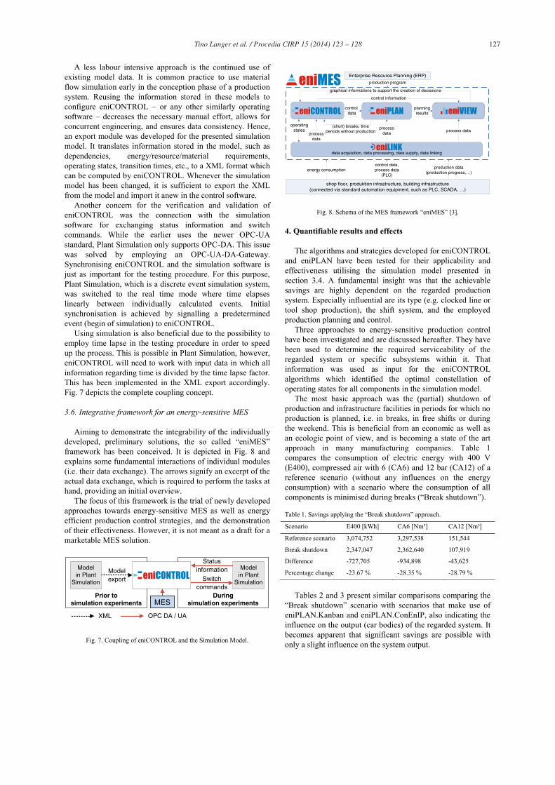
Transparency regarding all current and possibly projected energy and resource demands and flows are a main requirement for the energy efficient management of factories. Concepts for increasing the transparency by means of a web-based software solution have been developed and implemented prototypically in eniVIEW (Fig. 5). Aside of the live display of resource consumption data, eniVIEW assists in the identification of large energy or resource consumers.
Along with these monitoring aspects, interfaces have been investigated which allow for the visualisation of appropriate data supplied by third-party software systems. The implementation of eniVIEW is based on the visualisation framework “met – measurement evaluation toolkit” developed by Fraunhofer IWU.
3.4. Simulation-driven verification of concepts and solutions
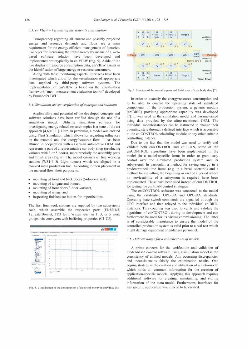
Applicability and potential of the developed concepts and software solutions have been verified through the use of a simulation model. Utilising simulation software for investigating energy related research topics is a state of the art approach [4,6,10,11]. Here, in particular, a model was created using Plant Simulation which allows for regarding influences on the material and the energy/resource flow. It has been attuned in cooperation with a German automotive OEM and represents a part of a representative car body shop (producing variants with 3 or 5 doors), more precisely the assembly parts and finish area (Fig. 6). The model consists of five working stations (WS1-4 & Light tunnel) which are aligned in a clocked main production line. According to their placement in the material flow, their purpose is:
mounting of front and back doors (5-door-variant), mounting of tailgate and bonnet, mounting of front door (3-door-variant), mounting of wings, and inspecting finished car bodies for imperfections.
The first four work stations are supplied by two subsystems each, which assemble the respective parts (FD5/RD5, Tailgate/Bonnet, FD3 le/ri, Wings le/ri) in 1, 3, or 5 work groups, via conveyors with buffering properties (C1-C8).
Fig. 5. Visualisation of the consumption of electrical energy in eniVIEW [8].
Ventilationzone 1
Ventilationzone 2
LZ 5 LZ 8LZ 7LZ 6
Ventilationzone 3
LZ 3
Shop floor
LZ 2LZ 1
Lighting zone 9
LZ 4
C5 C7 C8
FrameLighttunnel
Wings ri
WS1 WS3 WS4
Wings le
WS2
C4C3C2C1
BTail-gate
CA
Paintshop
C6
Bonnet
A
B
D
E
CFD5
A
B
D
E
CRD5
BFD 3
leCA
BFD 3
riCA
Fig. 6. Structure of the assembly parts and finish area of a car body shop [7].
In order to quantify the energy/resource consumption and to be able to control the operating state of simulated components of the production system, a generic module (eniBRIC) providing appropriate capability was developed [7]. It was used in the simulation model and parameterised using data provided by the afore-mentioned OEM. The individual moduleinstances can be instructed to change their operating state through a defined interface which is accessible to the eniCONTROL scheduling module or any other suitable controlling instance.
Due to the fact that the model was used to verify and validate both eniCONTROL and eniPLAN, some of the eniCONTROL algorithms have been implemented in the model (in a model-specific form) in order to grant easy control over the simulated production system and its subsystems. In particular, a method for saving energy in a predetermined time frame (e.g. in a break scenario) and a method for signalling the beginning or end of a period where no serviceability of a subsystem is required have been implemented. These have been used instead of eniCONTROL for testing the eniPLAN control strategies.
The eniCONTROL software was connected to the model using the established OPC-UA and OPC-DA standards. Operating state switch commands are signalled through the OPC interface and then relayed to the individual eniBRIC instances. This coupling was used to verify and validate the algorithms of eniCONTROL during its development and can furthermore be used for its virtual commissioning. The latter is of considerable importance to ensure the model of the controlled production system is valid prior to a real test which might damage equipment or endanger personnel.
3.5. Data exchange for a consistent use of models
A prime concern for the verification and validation of model-based control software using a simulation model is the consistency of utilised models. Any occurring discrepancies and inconsistencies falsify the examination results. One coping strategy is the creation and utilisation of a meta-model which holds all common information for the creation of application-specific models. Applying this approach requires additional software for creating, maintaining, and storing information of the meta-model. Furthermore, interfaces for any specific application would need to be created.
127 Tino Langer et al. / Procedia CIRP 15 ( 2014 ) 123 – 128
A less labour intensive approach is the continued use of existing model data. It is common practice to use material flow simulation early in the conception phase of a production system. Reusing the information stored in these models to configure eniCONTROL – or any other similarly operating software – decreases the necessary manual effort, allows for concurrent engineering, and ensures data consistency. Hence, an export module was developed for the presented simulation model. It translates information stored in the model, such as dependencies, energy/resource/material requirements, operating states, transition times, etc., to a XML format which can be computed by eniCONTROL. Whenever the simulation model has been changed, it is sufficient to export the XML from the model and import it anew in the control software.
Another concern for the verification and validation of eniCONTROL was the connection with the simulation software for exchanging status information and switch commands. While the earlier uses the newer OPC-UA standard, Plant Simulation only supports OPC-DA. This issue was solved by employing an OPC-UA-DA-Gateway. Synchronising eniCONTROL and the simulation software is just as important for the testing procedure. For this purpose, Plant Simulation, which is a discrete event simulation system, was switched to the real time mode where time elapses linearly between individually calculated events. Initial synchronisation is achieved by signalling a predetermined event (begin of simulation) to eniCONTROL.
Using simulation is also beneficial due to the possibility to employ time lapse in the testing procedure in order to speed up the process. This is possible in Plant Simulation, however, eniCONTROL will need to work with input data in which all information regarding time is divided by the time lapse factor. This has been implemented in the XML export accordingly. Fig. 7 depicts the complete coupling concept.
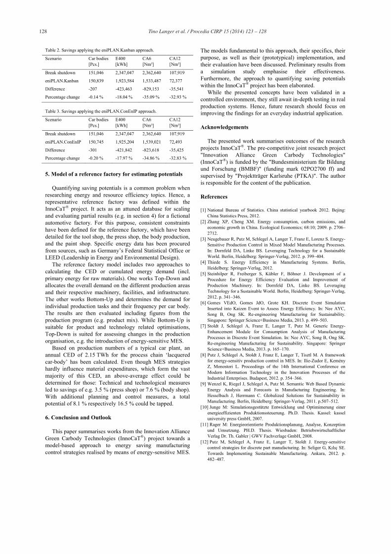
3.6. Integrative framework for an energy-sensitive MES
Aiming to demonstrate the integrability of the individually developed, preliminary solutions, the so called “eniMES” framework has been conceived. It is depicted in Fig. 8 and explains some fundamental interactions of individual modules (i.e. their data exchange). The arrows signify an excerpt of the actual data exchange, which is required to perform the tasks at hand, providing an initial overview.
The focus of this framework is the trial of newly developed approaches towards energy-sensitive MES as well as energy efficient production control strategies, and the demonstration of their effectiveness. However, it is not meant as a draft for a marketable MES solution.
Prior tosimulation experiments
Duringsimulation experiments
Modelexport Switch
commands
Statusinformation
XML OPC DA / UA
MES
Modelin Plant
Simulation
Modelin Plant
SimulationeniCONTROL
Fig. 7. Coupling of eniCONTROL and the Simulation Model.
data acquisition, data processing, data supply, data linking
processdata
process dataoperating
states
control information
planningresults
(short) breaks, timeperiods without production
controldata
processdata
energy consumptioncontrol data,process data
(PLC)
production data(production progress,…)
production program
Enterprise Resource Planning (ERP)
shop floor, produktion infrastructure, building infrastructure(connected via standard automation equipment, such as PLC, SCADA, …)
graphical informations to support the creation of decissions
eniMES
eniCONTROL eniPLAN eniVIEW
eniLINK
Fig. 8. Schema of the MES framework “eniMES” [3].
4. Quantifiable results and effects
The algorithms and strategies developed for eniCONTROL and eniPLAN have been tested for their applicability and effectiveness utilising the simulation model presented in section 3.4. A fundamental insight was that the achievable savings are highly dependent on the regarded production system. Especially influential are its type (e.g. clocked line or tool shop production), the shift system, and the employed production planning and control.
Three approaches to energy-sensitive production control have been investigated and are discussed hereafter. They have been used to determine the required serviceability of the regarded system or specific subsystems within it. That information was used as input for the eniCONTROL algorithms which identified the optimal constellation of operating states for all components in the simulation model.
The most basic approach was the (partial) shutdown of production and infrastructure facilities in periods for which no production is planned, i.e. in breaks, in free shifts or during the weekend. This is beneficial from an economic as well as an ecologic point of view, and is becoming a state of the art approach in many manufacturing companies. Table 1 compares the consumption of electric energy with 400 V (E400), compressed air with 6 (CA6) and 12 bar (CA12) of a reference scenario (without any influences on the energy consumption) with a scenario where the consumption of all components is minimised during breaks (“Break shutdown”).
Table 1. Savings applying the “Break shutdown” approach.
Scenario E400 [kWh] CA6 [Nm³] CA12 [Nm³]
Reference scenario 3,074,752 3,297,538 151,544
Break shutdown 2,347,047 2,362,640 107,919
Difference -727,705 -934,898 -43,625
Percentage change -23.67 % -28.35 % -28.79 %
Tables 2 and 3 present similar comparisons comparing the
“Break shutdown” scenario with scenarios that make use of eniPLAN.Kanban and eniPLAN.ConEnIP, also indicating the influence on the output (car bodies) of the regarded system. It becomes apparent that significant savings are possible with only a slight influence on the system output.
128 Tino Langer et al. / Procedia CIRP 15 ( 2014 ) 123 – 128
Table 2. Savings applying the eniPLAN.Kanban approach.
Scenario Car bodies [Pcs.]
E400 [kWh]
CA6 [Nm³]
CA12 [Nm³]
Break shutdown 151,046 2,347,047 2,362,640 107,919
eniPLAN.Kanban 150,839 1,923,584 1,533,487 72,377
Difference -207 -423,463 -829,153 -35,541
Percentage change -0.14 % -18.04 % -35.09 % -32.93 %
Table 3. Savings applying the eniPLAN.ConEnIP approach.
Scenario Car bodies [Pcs.]
E400 [kWh]
CA6 [Nm³]
CA12 [Nm³]
Break shutdown 151,046 2,347,047 2,362,640 107,919
eniPLAN.ConEnIP 150,745 1,925,204 1,539,021 72,493
Difference -301 -421,842 -823,618 -35,425
Percentage change -0.20 % -17.97 % -34.86 % -32.83 %
5. Model of a reference factory for estimating potentials
Quantifying saving potentials is a common problem when researching energy and resource efficiency topics. Hence, a representative reference factory was defined within the InnoCaT® project. It acts as an attuned database for scaling and evaluating partial results (e.g. in section 4) for a fictional automotive factory. For this purpose, consistent constraints have been defined for the reference factory, which have been detailed for the tool shop, the press shop, the body production, and the paint shop. Specific energy data has been procured from sources, such as Germany’s Federal Statistical Office or LEED (Leadership in Energy and Environmental Design).
The reference factory model includes two approaches to calculating the CED or cumulated energy demand (incl. primary energy for raw materials). One works Top-Down and allocates the overall demand on the different production areas and their respective machinery, facilities, and infrastructure. The other works Bottom-Up and determines the demand for individual production tasks and their frequency per car body. The results are then evaluated including figures from the production program (e.g. product mix). While Bottom-Up is suitable for product and technology related optimisations, Top-Down is suited for assessing changes in the production organisation, e.g. the introduction of energy-sensitive MES.
Based on production numbers of a typical car plant, an annual CED of 2.15 TWh for the process chain ‘lacquered car-body’ has been calculated. Even though MES strategies hardly influence material expenditures, which form the vast majority of this CED, an above-average effect could be determined for those: Technical and technological measures led to savings of e.g. 3.5 % (press shop) or 7.6 % (body shop). With additional planning and control measures, a total potential of 8.1 % respectively 16.5 % could be tapped.
6. Conclusion and Outlook
This paper summarises works from the Innovation Alliance Green Carbody Technologies (InnoCaT®) project towards a model-based approach to energy saving manufacturing control strategies realised by means of energy-sensitive MES.
The models fundamental to this approach, their specifics, their purpose, as well as their (prototypical) implementation, and their evaluation have been discussed. Preliminary results from a simulation study emphasise their effectiveness. Furthermore, the approach to quantifying saving potentials within the InnoCaT® project has been elaborated.
While the presented concepts have been validated in a controlled environment, they still await in-depth testing in real production systems. Hence, future research should focus on improving the findings for an everyday industrial application.
Acknowledgements
The presented work summarises outcomes of the research projects InnoCaT®. The pre-competitive joint research project "Innovation Alliance Green Carbody Technologies" (InnoCaT®) is funded by the "Bundesministerium für Bildung und Forschung (BMBF)" (funding mark 02PO2700 ff) and supervised by "Projektträger Karlsruhe (PTKA)". The author is responsible for the content of the publication.
References
[1] National Bureau of Statistics. China statistical yearbook 2012. Bejing: China Statistics Press, 2012.
[2] Zhang XP, Cheng XM. Energy consumption, carbon emissions, and economic growth in China. Ecological Economics; 68:10; 2009. p. 2706–2712.
[3] Neugebauer R, Putz M, Schlegel A, Langer T, Franz E, Lorenz S. Energy-Sensitive Production Control in Mixed Model Manufacturing Processes. In: Dornfeld DA, Linke BS. Leveraging Technology for a Sustainable World. Berlin, Heidelberg: Springer-Verlag, 2012. p. 399–404.
[4] Thiede S. Energy Efficiency in Manufacturing Systems. Berlin, Heidelberg: Springer-Verlag, 2012.
[5] Steinhilper R, Freiberger S, Kübler F, Böhner J. Development of a Procedure for Energy Efficiency Evaluation and Improvement of Production Machinery. In: Dornfeld DA, Linke BS. Leveraging Technology for a Sustainable World. Berlin, Heidelberg: Springer-Verlag, 2012. p. 341–346.
[6] Gomes VEdO, Gomes JdO, Grote KH. Discrete Event Simulation Inserted into Kaizen Event to Assess Energy Efficiency. In: Nee AYC, Song B, Ong SK. Re-engineering Manufacturing for Sustainability. Singapore: Springer Science+Business Media, 2013. p. 499–503.
[7] Stoldt J, Schlegel A, Franz E, Langer T, Putz M. Generic Energy-Enhancement Module for Consumption Analysis of Manufacturing Processes in Discrete Event Simulation. In: Nee AYC, Song B, Ong SK. Re-engineering Manufacturing for Sustainability. Singapore: Springer Science+Business Media, 2013. p. 165–170.
[8] Putz J, Schlegel A, Stoldt J, Franz E, Langer T, Tisztl M. A framework for energy-sensitiv production control in MES. In: Ilie-Zudor E, Kemény Z, Monostori L. Proceedings of the 14th International Conference on Modern Information Technology in the Innovation Processes of the Industrial Enterprises. Budapest, 2012. p. 354–366.
[9] Wenzel K, Riegel J, Schlegel A, Putz M. Semantic Web Based Dynamic Energy Analysis and Forecasts in Manufacturing Engineering. In: Hesselbach J, Herrmann C. Globalized Solutions for Sustainability in Manufacturing. Berlin, Heidelberg: Springer-Verlag, 2011. p.507–512.
[10] Junge M: Simulationsgestützte Entwicklung und Optimimerung einer energieeffizienten Produktionssteuerung. Ph.D. Thesis. Kassel: kassel university press GmbH, 2007.
[11] Rager M: Energieorientierte Produktionsplanung, Analyse, Konzeption und Umsetzung. PH.D. Thesis. Wiesbaden: Betriebswirtschaftlicher Verlag Dr. Th. Gabler | GWV Fachverlage GmbH, 2008.
[12] Putz M, Schlegel A, Franz E, Langer T, Stoldt J. Energy-sensitive control strategies for discrete part manufacturing. In: Seliger G, Kılıç SE. Towards Implementing Sustainable Manufacturing. Ankara, 2012. p. 482–487.