Embed Size (px)
Citation preview
A Methodology for Wireless Sensor Network Prototyping with Sophisticated
Debugging Support
Heiko Hinkelmann, Andreas Reinhardt, Manfred Glesner
Institute of Microelectronic Systems, Technische Universitat Darmstadt
Karlstrasse 15, 64283 Darmstadt, Germany
Abstract
In this paper, we present a methodology for rapid pro-
totyping of wireless sensor networks that allows to embed
sophisticated debugging functionality in a mote prototype
and thereby monitor entire networks. We achieve this goal
by combining two fundamental concepts: the use of a re-
configurable sensor node prototype platform, and an auxil-
iary network structure for granting a reliable communica-
tion channel for runtime debugging without interfering with
the primary radio link. For the prototype platform, we pro-
pose a modular design which incorporates a single FPGA
with high gate count as core of the platform. The FPGA
is utilized to emulate arbitrary mote architectures and re-
alize flexible interfaces to sensors and radio transceivers.
As a major benefit, versatile debugging interfaces can ad-
ditionally be implemented in the same FPGA, seamlessly
integrating into the emulated mote architecture, with direct
access to internal information. This easily allows to realize
passive system monitors as well as active debugging con-
trol. By using a deployment support network to exchange
relevant information, all motes can be monitored and con-
trolled simultaneously by a user. The paper presents the
proposed methodology, its implementation, and a practical
application example in detail.
1. Introduction
Wireless sensor networks (WSNs) typically consist of
many autonomous nodes (motes), each being equipped with
a radio transceiver, sensors, and an autonomous power sup-
ply [2]. For a large number of WSN applications, function-
ality is desired that exceeds simple data collection and re-
quires to perform data processing locally on the motes, e.g.,
specific sensor signal processing, localization, or object and
event tracking [9]. Mote architectures for such smartWSNs
therefore often comprise dedicated hardware components
(e.g., coprocessors, ASIC blocks, or reconfigurable units)
to achieve low energy consumption for data processing and
meet the stringent energy constraints of WSNs [7, 18, 12].
The design of smart mote systems can therefore become
rather complex.
A design flow for smart motes typically includes the
design and verification of synthesizable HDL models of a
mote system. Generic prototype platforms then allow rapid
prototyping of complete WSNs using the mote models and
allow to test them under realistic conditions before chip
manufacturing is started. However, smart motes have some
unique requirements and hence demand special prototype
platforms; they need to be very flexible, small, autonomous,
provide wireless communication, and support a wide range
of possible sensors for different application domains. Also,
remote access to a prototype mote is desired to obtain test
data and status information from all over a network. Since
this communication should not interfere with a mote’s reg-
ular operation and the primary radio link, an auxiliary de-
ployment support network (DSN) [5, 24] can be added to
achieve reliable network-wide observability during runtime.
As main contribution of this paper, a methodology for
prototyping smart WSNs is presented which accounts for
the aforementioned problems and provides additional de-
bugging support. We propose a design concept for a re-
configurable prototype platform which uses a single FPGA
with high gate count in order to emulate the complete digital
subsystem of a mote and provide a highly flexible solution
for sensor interfacing and implementing wireless communi-
cation protocols. Our methodology furthermore combines
this platform concept with the use of a deployment support
network. As a synergy effect of this combination, we gain
the potential for implementing sophisticated debugging op-
tions in the motes: free resources of the FPGA can be used
to integrate debugging interfaces for active control and pas-
sive monitoring directly into the emulated mote architec-
tures. Thus, detailed information about a mote can be gath-
ered during runtime, filtered for relevance, and sent over the
DSN to a central PC. As many motes in a WSN can be ac-

cessed over the DSN simultaneously, users are strongly as-
sisted in monitoring and controlling complete WSNs. The
proposed prototyping methodology thus not only aids hard-
ware development of new mote architectures, but also im-
proves software, protocol and application development.
The rest of this paper is organized as follows. Chap-
ter 2 presents our prototyping methodology and discusses
its underlying concepts. Hardware implementations of a re-
configurable prototype platform and a DSN base board will
be presented in chapter 3. A practical application example
for prototyping a mote architecture is given in chapter 4 and
demonstrates a complete debugging solution based on our
methodology. Chapter 5 concludes the paper with a final
summary and evaluation of the proposed methodology.
2. Methodology for WSN Prototyping
2.1. Mote Prototype Design Concepts
Our prototype platform concept envisions four separate
layers for sensing, communication, processing, and power
supply [11]. Such a layered design approach has proven
to be well suited for motes and has been applied similarly
in [17, 16, 13]. It allows to exchange layer implementations
independently of each other (e.g., to equip the platform with
different sensor types), thus making this modular platform
very generic and easily reusable. A schematic overview is
given Fig. 1.
The core of the processing layer will be an FPGA with
high gate count, which is intended to emulate the digital
subsystem of a prototyped mote architecture. Since the pri-
mary objective of our platform is the prototyping of smart
motes, which possibly have high system complexity [12, 7],
an FGPA with a considerable amount of logic resources is
required. Two additional major objectives will be met by us-
ing a large FPGA: it enables very flexible interfacing, and
it provides advanced debugging capabilities for the proto-
types. The concept to entirely map processing, interfacing
and debugging support to a single FPGA is a major dif-
ference to previous FPGA-based mote platforms, such as
[17, 16, 13], where FPGAs were often used in conjunction
with a microcontroller.
For the prototyping and testing of different wireless com-
munication schemes, it is essential to allow the implementa-
tion of various protocols on the platform and keep the proto-
type hardware flexible. Therefore, the use of a light-weight
radio transceiver chip providing a physical layer implemen-
tation only is proposed. Thus it becomes possible to imple-
ment the higher layers, particularly the MAC layer, within
the FPGA and specify them freely. Designers can exploit
this freedom to test different communication protocols or
to prototype systems that comprise specific hardware com-
ponents for data processing at the MAC layer. In case the
Figure 1. Schematic view of the implementedmote prototype platform showing the four layers for sensing, communication, processing
and power supply (from top to bottom)
use of a specific radio transceiver is preferred over a flex-
ible solution (because its application to the end product is
already known), the layered prototype design easily allows
to replace the flexible implementation by a more specific
one using the desired transceiver chip.
Besides wireless communication, sensing capabilities
are the second specific feature a mote prototype platform
needs to provide. The sensing layer enables the use of arbi-
trary sensor types with the prototype platform and allows to
replace them easily by providing a simple plug-in mecha-
nism. A slot-based concept is employed to connect small
sensor modules to the platform. The slots are kept uni-
versal and provide the connection to generic FPGA pins,
thus enabling to use the FPGA for implementing any digital
interface to the sensors. Similar approaches to use field-
programmable devices as flexible sensor interfaces have
been proposed in [17, 15]. Small PCB boards are used to
create customized sensor modules, possibly containing ad-
ditional components like A/D converters for analog sensor
outputs. This modular approach allows to equip the pro-
totype platform with arbitrary sensor types and thus use it
flexibly for a wide range of WSN applications.
A drawback of many regular FPGA boards used for pro-
totyping is that they must be mains-operated. This clearly
restricts their suitability for prototyping motes, as it reduces
their autonomy and mobility much. On the other hand, FP-
GAs tend to have a much higher power consumption than
average motes. Consequently, powering the FPGA board
by batteries will result in comparably short life-times and
will require to recharge the batteries frequently. To achieve
a suitable compromise, we therefore provide two instances
for the power supply layer of our prototype platform that
can be used optionally. A battery-powered version makes
the motes highly autonomous and is most suitable for ex-
periments with mobile motes or in environments without
power infrastructure. For long-term experiments, a mains-
operated version is available.
2.2. WSN Debugging Systems
As only limited models for real-life environments and
mote hardware can be utilized in network simulations, run-
ning and debugging applications on deployed mote plat-
forms is an essential component in the verification process
of WSNs. While in principle the primary radio link of the
motes could be used for the exchange of debugging infor-
mation, two major problems can arise with this solution:
firstly, the transmissions can interfere with the regular traf-
fic, thereby altering the application behavior. And secondly,
link reliability problems may occur, particularly when new
communication protocols are being tested. Therefore, aux-
iliary deployment support networks are often used for pro-
viding an independent reliable communication channel for
debugging and monitoring [5, 24]. Comparing existing so-
lutions to debug a deployed WSN, we propose grouping
them depending on the extent of integration with the motes.
Active debugging systems directly interact with the
motes. Different levels of debugging can be realized, from
the simple task of sending textual debug messages over the
DSN up to the option of reading and manipulating memory
contents. Breakpoints in the program code and exceptions
during runtime can also trigger active systems to take ac-
tion. However, active solutions impose the management of
the DSN connection on the mote, and hence possibly alter
the mote behavior. Current active debugging systems com-
prise the USB-based TWIST infrastructure [10], Bluetooth-
based deployment support networks using BTnodes [4], and
the Sympathy debugging system [19] which integrates with
the program code and forwards maintenance messages us-
ing the on-board radio transmitter.
Passive debugging structures do not directly interact with
the motes but instead monitor available signals to determine
proper mote operation. A common approach is the analysis
of packets on the radio. The amount of monitored pack-
ets and the packet payload are hereby analysed regarding
compliance with predefined metrics to determine erroneous
behaviour. Monitored data is then transmitted to a central
node on the DSN, where it is cumulated and prepared for
analysis. Examples for this passive debugging systems in-
clude the Sensor Network Inspection Framework [21] and
the SpyGlass sensor network visualiser [6].
Our methodology targets to select the optimum trade-
off between the extent of debugging and the resulting im-
pact on the mote behavior. As active solutions generally
impose additional management tasks on the mote, we pro-
pose the use of a hybrid approach: exploiting the inherent
characteristics of an FPGA, a dedicated debugging unit is
integrated with the platform, providing the support for both
active and passive debugging tasks. The connection to the
DSN is managed by this subsystem, which is a major advan-
tage over existing solutions, as it exhibits no impact on the
mote behavior. Various debugging interfaces with access
to the DSN connection can then be designed and integrated
into the motes.
2.3. Embedded Debugging Interfaces
As mentioned in Sec. 2.1, the proposed methodology is
based on the idea of using a single FPGA for hardware emu-
lation, sensor and radio interfacing, and debugging support.
As a major advantage, this allows to integrate debugging
interfaces seamlessly into the mote architecture without in-
fluencing its original structure. All relevant signals, includ-
ing sensor data and radio packets, are generally accessible
within the FPGA and thus possible targets for monitoring
or active control. Hence, designers can choose from a huge
variety of options for debugging interfaces and can optimize
them for the given requirements and emulated mote archi-
tectures. A representative subset of available options is pre-
sented in the following to get an overview of the versatile
debugging possibilities.
Common monitoring solutions include the observation
of sensor data, incoming and outgoing radio packets, and
internal status information of processors, such as the con-
tents of error registers. Bus snooping is also a common
technique, which reveals most of the current behavior of
a mote when applied to a central system or memory bus.
More dedicated monitors can generate statistics about the
radio link quality or about specific hardware components
(activity, duty-cycles of power saving modes, etc.), e.g., to
refine high-level simulation models. In general, monitored
data can be transmitted in regular time intervals, on request,
or event-triggered. Furthermore, internal evaluation of de-
bugging information is possible for reducing the workload
of the DSN, e.g., by applying filters to the monitored data
or by reacting to violations of predefined metrics only.
Entirely unaltered mote behavior is observed when the
debugging extension only performs passive monitoring of
internal signals and processor registers, allowing to gain
deep insights into the mote behavior. Active debugging
solutions extend the range of possibilities and include the
use of breakpoints, transmission of software-generated text
messages over the DSN, remote system control (for halting
or resuming operation, resetting, etc.), or reading and mod-
ification of memory contents.
Our methodology does not restrict the type of debugging
interface to be used but provides designers with the general
possibility to specify them freely. It does not rely on a spe-
cific DSN medium either, but offers freedom of choice to
the user. The debugging system is completed with a soft-
ware tool to access the debug interfaces of the motes over
the DSN and supervise the monitoring and debugging pro-
cess from a central PC. A complete example, taken from a
real test case, will be given in Sec. 4.
3. Hardware Implementation
In compliance with the proposed methodology, a recon-
figurable prototype platform [11] and a base board [20] with
DSN connection have been developed according to the de-
sign concepts discussed in Sec. 2. The implementation of
both device types is explained in this section.
3.1. The Reconfigurable Prototype Platform
Our prototype platform follows the modular structure in-
troduced in Fig. 1. The processing layer of the prototype has
been realized by a Zefant XS3-2000 FPGA board [22, 23].
With a gate count of 2000k system gates, the employed
Spartan3 FPGA is suited for the realization of complex
mote systems and leaves sufficient resources for the imple-
mentation of sophisticated debugging interfaces. The board
provides over 250 generic I/O pins, which have partially
been used for the connection to other layers and the base
board. The radio transceiver (XEMICS DP-1203) and a pla-
nar antenna are included on a printed circuit board (PCB)
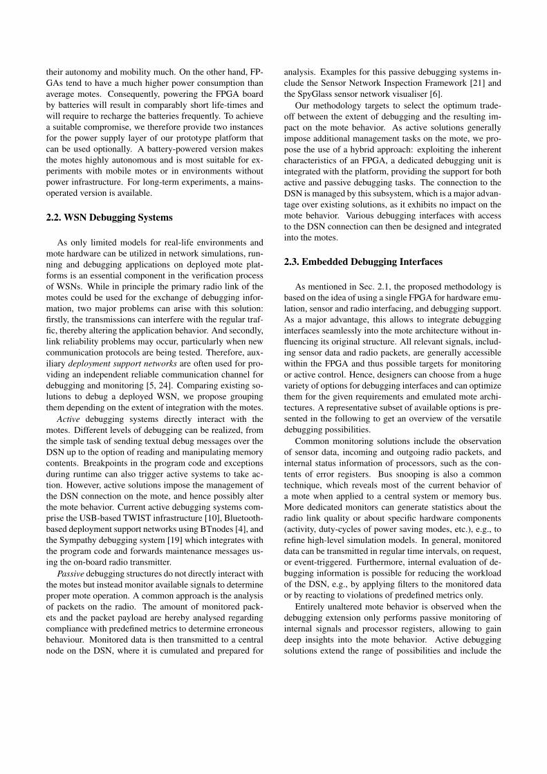
shown in Fig. 2. Small sensor modules can be plugged into
two slots on the PCB and thus be replaced easily. This al-
lows the use of a broad range of possible sensor types with
the prototype platform, leading to the expectation that this
platform can be used universally.
The prototypes can be powered either by batteries or by
a mains-operated base board. Four AA rechargeable bat-
teries in a box (shown in Fig. 2) can supply the prototype
for approximately 10 hours of constant operation when run-
ning real applications, measured in experimental results for
the example system in Sec. 4 with a 11 MHz clock. This
already exceeds the duration of many application experi-
ments. (Future platform implementations might use new
low-power FPGAs – e.g., Actel’s IGLOO family [1] – and
power management techniques to increase battery life-time
even further). For long-term experiments, the base board
can be used for power supply instead.
Figure 2. Photo of the prototype platform,showing the wireless communication PCB
with two sensor slots on top, the FPGA boardin the middle, and a battery box.
3.2. The DSN Base Board
The DSN base board can be understood as instance of
the power supply layer and replaces the battery version. Be-
sides providing mains-operated power supply, its main ob-
jective is to provide external connectivity, as illustrated in
Fig. 1. The base board therefore comprises a JTAG interface
for configuring the FPGA, a UART interface for loading the
flash memory of the Zefant board, and an Ethernet inter-
face for the DSN. We decided on using Ethernet as the DSN
medium since a wired solution provides much higher relia-
bility than wireless alternatives, which is an important fact
in debugging. Also, existing Ethernet infrastructure can be
used, which is available at most university buildings where
our experiments are going to take place.
The Ethernet interface consists of a common jack and
an ENC28J60 controller [14] implementing the MAC and
the physical layers. When a mote prototype is plugged into
the base board, the controller is directly connected to the
FPGA, where the higher level control functions for the DSN
are implemented. This FPGA-based control unit is inde-
pendent of the emulated mote architecture and manages the
DSN connection autonomously, thus keeping undesired in-
fluence on the original application behavior as low as pos-
sible. It interacts with the mote architecture only via the
embedded debugging interfaces.
4. Practical Application
A sample application is examined to demonstrate how
the proposed methodology and presented hardware devices
can be applied for prototyping and debugging a WSN. The

example originates from a current research project on smart
sensor networks, where we use the prototypes to test new
mote architectures incorporating coarse-grained reconfig-
urable hardware components [12] under realistic conditions.
4.1. Mote Architecture
The mote architecture from [12] is depicted in Fig. 3.
The core of this architecture is a hybrid system combining
a domain-specific, coarse-grained reconfigurable function
unit (RFU) with a modified 32-bit LEON2 RISC processor
core. The RFU is integrated directly into the processor’s
data path and improves the energy-efficiency for data pro-
cessing by up to two orders of magnitude [12]. The sys-
tem furthermore comprises on-chip memories, peripheral
components, and sensor and transceiver interfaces. It is de-
scribed in VHDL and intended to be fabricated as a system-
on-chip in 130nm standard cell technology.
Figure 3. Example mote architecture with detailed view of the debugging interface
4.2. Debugging Interface Design
Fig. 3 also illustrates a sample possibility for the inte-
gration of a debugging interface into the mote architecture,
which was implemented accordingly. This interface com-
prises a UDP over IP stack, forming a Virtual LAN when
connected to an existing network. In addition to trans-
ferring debugging information, it implements fundamental
Ethernet features such as the Address Resolution Protocol
(ARP), the echo command (ICMP Ping), and the correct
handling of broadcast messages. The platform’s IP and
MAC addresses can be manually configured by dedicated
DIP switches to avoid errors due to duplicate addresses
within the network.
The debugging unit implements several of the techniques
discussed in Sec. 2.3. As depicted in Fig. 3, all main system
components are connected by a central Wishbone bus. Con-
sequently, practically all application data passes the bus at
some stage and can be monitored by the debugging unit per-
forming bus snooping. A buffer is used to log information
about the origin (program counter value of load/store in-
structions), destination address and transmitted data of each
bus transfer. The destination address allows to identify sen-
sor data, radio packets, memory operations, etc. A mask,
which can be set by an external control packet received over
the DSN, is then applied to selectively log bus transfers of
interest only. The buffered content is eventually transmitted
as DSN packet each time the buffer capacity exceeds the
threshold value of 50%.
Processor status information is logged at regular time in-
tervals, and halting the processor (causing a pipeline stall),
resuming its operation, or resetting the mote can be con-
trolled remotely over the DSN. Halting can also be caused
by software breakpoints inserted in the application program
code. Finally, the option for sending software-defined text
messages is provided. The message data is simply written
to a dedicated address on the Wishbone bus and thereby de-
tected by the bus snooping mechanism.
4.3. Host PC Software for Debugging
In order to manage the monitoring and debugging of a
WSN, a user-friendly software tool has been created in Java.
It runs on a central host PC that is connected to the DSN.
The tool establishes and manages DSN connections to the
motes and provides a graphical user interface (GUI) for the
control of the motes. This GUI allows a user to select the
motes he wants to access, display monitored data, configure
bus masks, and send control commands. Start, stop and re-
set commands can be sent either to individual motes or to all
devices connected to the WSN. The tool allows to manage
a WSN during runtime as well as to write all debug infor-
mation to a log file for off-line analysis.
Fig. 4 shows a screenshot of the GUI output during one
of our test applications. Each line represents one bus trans-
fer that has been recorded by the bus snooping mechanism.
Program counter, bus address, direction (W for write, R for
read), and data (in binary, hex and ASCII format) are dis-
played. The bus address FFFFFFFC indicates a software-
generated text message (see Sec. 4.2). The monitored mote
runs an application for generating statistics about the radio
link quality. For instance, the first statistics message shown
in Fig. 4 indicates that the latest received sequence num-
ber was 389 (0x185), that six packets out of the last hun-
dred were lost, while 88 (0x58) were received with a correct

Figure 4. Debugging messages displayed on the GUI.
checksum and another six had a wrong CRC value. Compa-
rable statistics messages with updated information are sent
regularly for every hundred packets and thus allow to mon-
itor changes in the radio link quality during runtime.
5. Conclusion
Based on our experience with the prototyping of WSNs,
we derived a general prototyping methodology for this do-
main that provides sophisticated debugging support. The
key concept of our methodology is to combine the tech-
nique of deployment support networks with the usage of
reconfigurable mote prototype platforms that are based on
a single FPGA solution. As a resulting synergy effect, we
achieve the potential to realize advanced debugging support
for entire WSNs: free resources of the FPGA can be used to
integrate versatile debugging interfaces seamlessly into the
motes, while the DSN allows a user to access these inter-
faces remotely and thereby monitor and control many motes
simultaneously from a single host PC during runtime.
The application of the proposed methodology to a real
test case has been demonstrated. A flexible mote prototype
platform with modular structure has been designed and was
presented. The employed Spartan3-2000 FPGA was found
to provide sufficient resources to realize mote system emu-
lation, sensor and radio interfacing, and debugging support
all in a single device, which is an essential concept of our
methodology. Emulation of the demonstrated example ar-
chitecture of a complex smart mote consumed 60% of this
FPGA’s logic resources. Additional 15% were required for
the presented debugging interface, providing the aforemen-
tioned blend of active and passive debugging features. The
complete debugging solution presented in this paper fur-
thermore comprises an Ethernet-based DSN, a base board,
and a software tool providing a GUI for managing the DSN
and the debugging process from a remote host computer.
An Ethernet connection has been chosen as the underly-
ing DSN medium in our sample implementation, providing
both a high reliability of packet transmissions and suitable
infrastructures present in many buildings. In general how-
ever, our prototyping methodology neither relies on a spe-
cific DSNmedium, nor does it restrict the type of debugging
interface to be used. Both can be chosen freely by design-
ers, including the option of using wired or wireless DSNs.
The proposed prototyping methodology represents a sig-
nificant increase in the possibilities for analyzing and ver-
ifying the functionality of WSNs in addition to computer
aided simulations. It allows rapid prototyping of complete
networks and thus testing new mote architectures, com-
munication protocols, and many other system features un-
der realistic conditions before costly chip manufacturing is
started. The ability to integrate versatile monitoring and de-
bugging features directly into the motes moreover allows
to gather detailed information about mote behavior with as
small influence on emulated architectures and application
behavior as possible. By allowing seamless access even to
internal signals of the motes, system observability during
runtime is improved radically. The availability of such de-
tailed information can help to find and eliminate bugs in the
mote hardware or in WSN applications, as well as to gen-
erate statistics on characteristic system functions and hard-
ware components for the refinement of high-level simula-
tion models. Summarizing, our prototyping methodology
is therefore useful for a wide range of purposes and aids
hardware, software, protocol and application development.
Particularly in the domain of smart sensor networks, the
prototyping and analysis of heterogeneous WSNs is of great
interest. Our prototype platform allows to emulate arbitrary

mote architectures on the FPGA, so motes with different
architectures can be realized easily in the same network by
still using only one type of prototype platform. Likewise,
debugging interfaces can be varied for different motes in
a heterogeneous WSN. Since the sensor modules of each
mote can also be exchanged easily, the platform can expose
heterogeneity for sensing capabilities, debugging features,
and system architectures.
Using FPGAs in end products for motes is a fascinating
option and promising research domain [17, 8, 3]. Currently,
the high power consumption of FPGAs with high gate count
is a critical handicap, but recent developments and trends in
the FPGA market (e.g., [1]) lead to the expectation that this
issue will be solved in the future. An FPGA-based smart
mote can clearly benefit from the same concepts proposed
for our prototypes, like realizing different system architec-
tures on the same mote platform or integrating optimized
debugging support seamlessly into the motes on demand.
6. Acknowledgements
This work is part of a research project funded by
the German Research Foundation (DFG) under grant no.
GL144/25-2.
References
[1] Actel Corporation. http://www.actel.com/products/IGLOO,
Jan. 2008.[2] I. Akyildiz, W. Su, Y. Sankarasubramaniam, and E. Cayirci.
A Survey on Sensor Networks. IEEE Communications Mag-
azine, 40:102–114, 2002.[3] Atific Oy Ltd. Atific Helicopter: Multi-radio Wire-
less Sensor Network (WSN) Development Platform.
http://www.atific.fi/en, June 2006.[4] J. Beutel, M. Dyer, M. Hinz, L. Meier, and M. Ringwald.
Next-Generation Prototyping of Sensor Networks. In Proc.
2nd Int. Conf. on Embedded Networked Sensor Systems,
pages 291–292, 2004.[5] J. Beutel, O. Kasten, F. Mattern, K. Romer, F. Siegemund,
and L. Thiele. Prototyping Wireless Sensor Network Appli-
cations with BTnodes. In Proc. 1st European Workshop on
Wireless Sensor Networks, 2004.[6] C. Buschmann, D. Pfisterer, S. Fischer, S. P. Fekete, and
A. Kroller. SpyGlass: Taking a Closer Look at Sensor Net-
works. In Proc. 2nd Int. Conf. on Embedded Networked Sen-
sor Systems, pages 301–302, 2004.[7] D. Dietterle, J.-P. Ebert, G. Wagenknecht, and R. Kraemer.
A Wireless Communication Platform for Long-Term Health
Monitoring. In 4th IEEE Conference on Pervasive Comput-
ing and Communications Workshops, 2006.[8] D. Efstathiou, K. Kazakos, and A. Dollas. Parrotfish: Task
Distribution in a Low Cost Autonomous ad hoc Sensor Net-
work through Dynamic Runtime Reconfiguration. In Proc.
14th Annual IEEE Symp. on Field-Programmable Custom
Computing Machines, 2006.
[9] D. Estrin, L. Girod, and G. P. M. Srivastava. Instrument-
ing the World with Wireless Sensor Networks. In Proc. Int.
Conf. on Acoustics, Speech and Signal Processing, 2001.[10] V. Handziski, A. Kopke, A. Willig, and A. Wolisz. TWIST:
A Scalable and Reconfigurable Testbed for Wireless Indoor
Experiments with Sensor Networks. In 2nd Int. Workshop
on Multi-hop Ad Hoc Networks: From Theory to Reality,
2006.[11] H. Hinkelmann, A. Reinhardt, S. Varyani, andM. Glesner. A
Reconfigurable Prototyping Platform for Smart Sensor Net-
works. In Proc. 4th Southern Programmable Logic Confer-
ence, March 2008.[12] H. Hinkelmann, P. Zipf, and M. Glesner. A Domain-
Specific Dynamically Reconfigurable Hardware Platform
for Wireless Sensor Networks. In Proc. Int. Conf. on Field-
Programmable Technology, 2007.[13] D. Lymberopoulos, N. Priyantha, and F. Zhao. mPlatform:
A Reconfigurable Architecture and Efficient Data Sharing
Mechanism for Modular Sensor Nodes. In Proc. 6th Int.
Conf. on Information Processing in Sensor Networks, 2007.[14] Microchip Technology Inc. ENC28J60 Data Sheet –
Stand-Alone Ethernet Controller with SPI Interface (version
DS39662B). http://www.microchip.com, 2006.[15] D. P. Morales, A. Garcıa, A. J. Palma, and A. Martınez-
Olmos. Merging FPGA and FPAA Reconfiguration Capa-
bilities for IEEE 1451.4 Compliant Smart Sensor Applica-
tions. In Proc. 3rd Southern Conference on Programmable
Logic, pages 217–220, 2007.[16] B. O’Flynn, S. Bellis, K. Delaney, J. Barton, S. C.
O’Mathuna, A. M. Barroso, J. Benson, U. Roedig, and
C. Sreenan. The Development of a Novel Minaturized Mod-
ular Platform for Wireless Sensor Networks. In Proc. 4th
Int. Symp. on Information Processing in Sensor Networks,
pages 370–375, 2005.[17] J. Portilla, T. Riesgo, and A. de Castro. A Reconfigurable
FPGA-Based Architecture for Modular Nodes in Wireless
Sensor Networks. In Proc. 3rd Southern Conference on Pro-
grammable Logic, pages 203–206, 2007.[18] J. Rabaey, M. Ammer, J. da Silva Jr., D. Patel, and
S. Roundy. PicoRadio supports ad hoc ultra-low power wire-
less networking. Computer Magazine, 33:42–48, 2000.[19] N. Ramanathan, K. Chang, R. Kapur, L. Girod, E. Kohler,
and D. Estrin. A Debugging System for Sensor Networks. In
Center for Embedded Networked Sensing Technical Report
47, 2005.[20] A. Reinhardt, H. Hinkelmann, and M. Glesner. Developing
a Debugging Interface for Reconfigurable Wireless Sensor
Nodes. In 7th European Workshop on Microelectronics Ed-
ucation, May 2008.[21] M. Ringwald and K. Romer. Monitoring and Debugging of
Deployed Sensor Networks. 2. GI/ITG KuVS Fachgesprach
Systemsoftware fur Pervasive Computing, Arbeitsberichte
des Instituts fur Informatik, vol. 38/5, 2005.[22] S. Schirrmann. Zefant XS3 FPGA Module Users Manual,
version 1.7. http://www.simple-solutions.de, 2007.[23] Trenz Electronic. http://www.trenz-electronic.de, 2007.[24] G. Werner-Allen, P. Swieskowski, and M. Welsh. MoteLab:
A Wireless Sensor Network Testbed. In Proc. of the 4th Int.
Symp. on Information Processing in Sensor Networks, 2005.

![Rapid Prototyping Methodology in Action: A Developmental …gmswan3/609/Jones_Richey_2000.pdf · Rapid Prototyping Methodology in Action: A Developmental Study [] ... enhances traditional](https://img.dokumen.tips/doc/110x75/5aef7fef7f8b9ac2468cdf6c/rapid-prototyping-methodology-in-action-a-developmental-gmswan3609jonesrichey2000pdfrapid.jpg)