Embed Size (px)
Citation preview
IEEJ Journal of Industry ApplicationsVol.8 No.4 pp.644–651 DOI: 10.1541/ieejjia.8.644
Paper
A Matrix-based Isolated Bidirectional AC-DC Converter with LCL typeInput Filter for Energy Storage Applications
Prathamesh Pravin Deshpande∗ Non-member, Amit Kumar Singh∗ Non-member
Hau Chong Aih∗ Non-member, Sanjib Kumar Panda∗ Non-member
(Manuscript received July 25, 2018, revised Jan. 28, 2019)
An isolated three-phase AC-DC converter is proposed in this paper for integrating energy storage elements such asbatteries to the utility grid. The proposed topology uses a matrix based AC-AC converter for three-phase to single-phase conversion, facilitates the use of high-frequency transformers for galvanic isolation, and provides the necessaryturns ratio for matching the required voltages on both sides, and uses a full-bridge controlled rectifier section for AC-DC conversion. A Space Vector Modulation (SVM) based switching technique is implemented for the matrix-basedconverter to obtain superior input power quality and improved power conversion efficiency, and Sinusoidal Pulse WidthModulation (SPWM) is used for the full bridge controlled rectifier. A T-shaped LCL input filter is developed to providelow-pass filtering effect. Also, the filter realizes an inductance dominance, which provides current source characteris-tics hence, only a capacitive output filter is used. The simulation was carried out using Powersim (PSIM) simulationsoftware. The variation of voltage gain for SVM and SPWM modulation indices is also presented. The converter isable to generate a charging voltage as well as three-phase sinusoidal voltage with a THD of 3%. A closed-loop controlis developed for the matrix type AC-AC converter part. The control is capable of performing bidirectional operation ofthe system. The proposed converter topology and switching scheme are experimentally verified.
Keywords: matrix, bidirectional, SVM, AC-AC, AC-DC, isolation
1. Introduction
With increase in the distributed generation and renewableenergy sources, use of energy storage devices has been in-creased. Integration of the storage elements with grid be-comes mandatory. Siddhartha Singh, et al., describes theconverters for renewable energy sources integration with theutility grid (1). Various power electronic converter topologiescan be applied. Isolated converters like full bridge DC-DCconverter could also prove a better option having the ad-vantages of high frequency transformer (turns ratio and gal-vanic isolation). Various modulation schemes for the convert-ers like Sinusoidal Pulse Width Modulation (SPWM), SpaceVector Modulation (SVM) etc. have been proposed and be-ing used. Hence, it is important to apply the knowledge andformulate a topology based on certain application and param-eters. A matrix based converter is multi-phase-to-multi-phaseAC-AC converter with an array of switches. Patrick Wheeler,et al., have presented a review and analysis on matrix basedconverter topology along with modulation and control strate-gies (2). Apart from modulation, the other point emphasizedwas of input filter. The filter is required to reduce the switch-ing harmonics going into the system. The filter must be ableto satisfy requirements such as having cutoff frequency lowerthan switching frequency (low pass), minimizing its reactivepower to grid, minimizing size of capacitors and inductors
∗ Department of Electrical and Computer Engineering, NationalUniversity of Singapore
and minimizing filter inductor voltage drop or impedance atrated current. Amit Kumar Singh, et al., presents, a non-isolated matrix based buck-boost converter applicable for theaircraft systems (3) and an isolated single-stage three-phaseAC-DC converter (4). Both applied the matrix topology toconvert low frequency AC to high frequency AC. The pro-posed converter overcomes the limitations expressed for con-ventional converters and provides output DC voltage with re-duced current distortion and improved power conversion ef-ficiency. The proposed converter eliminates the DC link ca-pacitor and combines the output filter inductors with induc-tors from other stages. As the proposed topology is operatedat higher modulation index and lower duty cycle, it promiseshigher input power quality and lower semiconductor losses.The merits make the proposed converter suitable for aircraftsystem, telecommunication, micro-grid and energy storage.The SVM has been selected for modulation scheme. ManuelOrtega, et al., S. Mahdi, et al., presents the bidirectional ca-pability of the matrix based converter (5)–(8). Particularly (5),and (7) developed matrix based topology for energy storageintegration to utility grid.Sadao Ishii, et al., proves the step-up and step-down capability of the matrix based converterand its implication in bidirectional power flow mode (6). De-shang Sha, et al., mentions the advantages of the proposedconverter which are high voltage conversion gain, high powerfactor, high conversion efficiency and high power density.However, due to input LC filter, an output inductor filter isrequired (7). Due to which for power flow towards the grid, acomprehensive modulation technique is required for matrix
c© 2019 The Institute of Electrical Engineers of Japan. 644
Matrix-based Isolated Bidirectional AC-DC Converter with LCL Input Filter(Prathamesh Pravin Deshpande et al.)
based converter to reduce Total Harmonic Distortion (THD).The main conclusion is the capability and smooth transi-tion of power flow direction for matrix topology. From (9)to (12), it is clear that, using SVM, the advantages stated arelower input current THD, lower duty-cycle loss, maximumoutput inductor current ripple and minimum switching losscomparing to other PWM schemes when the MOSFET de-vices are employed. Keping You, et al., explains the use ofthe same SVM algorithm for bidirectional power flow andSVM is able to produce better output performance, partic-ularly at low modulation indexes, in terms of output wave-form harmonic content (10). Similar results were obtainedfor multi-level neutral-point-clamped matrix based converteras described in (11), while Mehadad Kazerani, et al., shows,using SVM, the matrix based converter was able to performall aspects of frequency changing, real power flow control,and independent reactive power flow control on both sides (12).
Thus, it can be concluded that bidirectional matrix basedtopology with galvanic isolation, lower THD values, higherpower converter efficiency and power density using modula-tion schemes like SVM could form a competitive converterfor integrating an energy storage element like batteries or su-per capacitors to utility grid. Hence, considering this, theblock diagram of the proposed converter is as shown in Fig. 1.
The input three-phase voltages are first filtered using inputLC filter (section a) followed by matrix (3x1) topology (sec-tion b). The matrix topology converts the three-phase linefrequency AC voltages into an intermediate high frequencyAC voltage. The high frequency AC voltage is then fed toa H-bridge (section c) through an isolating transformer (T)which in turn, rectifies it to output DC voltage. This H-bridgealso inverts the DC power to high frequency AC which isconverted to line frequency and voltage by the matrix basedconverter and fed back to the grid. Moreover, the high fre-quency AC voltage reduces the passive filter elements andtransformer size and volume. The SVM based modulationscheme is proposed for the matrix based converter for im-proved input power quality. In summary, the novelty andcontributions of the paper are as follows:•Use of three-phase LCL (T-shaped) filter. This type of
filter provides inductive dominance from either termi-nals, which is required for bidirectional operation of theconverter.• The proposed SVM based modulation scheme requires
single control for each of the matrix switches and there-fore, does not need switch body diode conduction andtherefore, facilitates, reduced number of isolated gatedrivers (six for six matrix switches) and no body diodeloss (conduction loss and reverse recovery loss). More-over, the switching sequence is arranged symmetrically
(a) (b) (c)
Fig. 1. Block diagram of the proposed matrix based AC-DC converter
to provide symmetrical bipolar high frequency AC volt-age at the matrix output.•Use of full bridge controlled rectifier to perform AC-DC
as well as DC-AC operations. The load or energy stor-age device is connected to the H-bridge. Synchronousrectification can be carried out to provide lower conduc-tion losses while a simple control technique like SPWMcould be used for inversion operation.
The paper is organized as follows: Section II provides thedetails of the proposed topology and operation of the con-verter. In Section III, simulation of the converter is carriedout. In Section IV, results of the simulation are described.Section V provides the conclusion.
2. Topology and Principle of Operation
The proposed converter is as shown in Fig. 2.Each matrix switch set (S 1 to S 6) contains two back-to-
back connected switches.2.1 Filters The LCL filter topology is as shown in
Fig. 3.Applying superposition theorem to Fig. 3, for v2 = 0,
i2(s)v1(s)
=(L2C1)s2 + 1
(L1L22C2
1)s4 + (L22C1)s3 + (2L1L2C1)s2 + (L2)s + L1
· · · · · · · · · · · · · · · · · · · · · · · · · (1)
Where, v1 is an alternating source, i2 is the current by an-other alternating source v2, L1 and L2 are the filter inductorsand C1 is the filter capacitor.
For v1 = 0,
i2(s)v2(s)
=1
(L1L2)s2 +1
C1(L1 + L2)
· · · · · · · · · · · · · · · · · (2)
Where, v2 is an alternating source.Similarly, for v1 = 0,
i1(s)v2(s)
=(L1C1)s2 + 1
(L21L2C2
1)s4 + (L21C1)s3 + (2L1L2C1)s2 + (L1)s + L2
· · · · · · · · · · · · · · · · · · · · · · · · · (3)
Where, i1 is the current by source v1.From the analysis, it is clear that, the LCL type of filter
Fig. 2. Circuit topology for integrating energy storageelement to utility grid
Fig. 3. LCL filter analysis
645 IEEJ Journal IA, Vol.8, No.4, 2019

Matrix-based Isolated Bidirectional AC-DC Converter with LCL Input Filter(Prathamesh Pravin Deshpande et al.)
provides rejection of higher frequency signals i.e. showingthe low pass filtering effect. By comparing (1) and (3), it canbe observed that, the filter topology is symmetric and depend-ing on the values of all filter components, the LCL filter actslow pass or resonance filter for power flow in both directions.Further more, for L1 = L2, the filter is able to achieve sameresonance at the required frequency in both directions withappropriate selection of component values. Hence, the reso-nance could be set near to the line frequency to obtain lowerTHD values. Also, due to dominance of inductance, this typeof filter provides current source effect. To balance out, onlycapacitive output filter is required. This also provides the ad-vantage of using devices with lower ratings. The RC snubberis used to reduce the voltage spikes generated due to induc-tances in the circuit. As no output inductor is required, re-duction in snubber circuit as no LC filter oscillations will beinvolved in the output circuit.2.2 Modulation For operation of the matrix based
converter, the SVM is used. The reference voltages are si-nusoidal with phase difference of 120◦, frequency is of therequired high frequency AC and with magnitude defined bymodulation index.
The proposed converter operates in two regions, one is tosupply power to energy storage device and other is to restorepower to the grid back from the energy storage device. Thetwo regions are described in Sections 2.3 and 2.4 respectively.2.3 Charging of the Energy Storage using the Utility
Grid Power flows from the utility grid to the energy stor-age device. The full bridge controlled rectifier acts as rec-tifier to convert the high frequency AC to DC. The rectifi-cation could be done by using either the body diodes of thesemi conducting switches or by using synchronous rectifica-tion technique for MOSFET switches. The matrix based con-verter is switched using SVM. The reference sine wave forSVM is of frequency which is of the desired high frequencyAC signal.2.4 Discharging of the Energy Storage to the Utility
Grid The full bridge controlled rectifier acts as inverterto convert DC to high frequency AC. SVM is used for thematrix based converter while SPWM is used for the inverter.The reference sine wave for SPWM is of frequency which isof desired high frequency AC signal and compared with highfrequency triangular wave. The reference sine wave for SVMwill be the line frequency.
3. Simulation of the Proposed Converter
The simulation was carried out using PSIM (Version 10.0)software. A comprehensive simulation model was con-structed with the parameters as mentioned. The parametersrequired for the simulation model is as expressed in Table 1.
The high frequency transformer not only provides isolationbut also scaling of voltage. From calculations and simula-tion, it was observed that, the turns ratio plays a critical rolewhen the energy is been transferred from energy storage ele-ment to the grid. Using the selected parameters, bode plot forequivalent i2 using equations 1 and 2 is given by Fig. 4. Theobserved gain margin is −27.4 dB at 745 rad/sec and phasemargin is 13.3◦ at 726 rad/sec. Thus, for the selected val-ues, the resonance peak occurs aroung 115 Hz, providing thelow filtering effect. Negative gain margin and positive phase
Table 1. Simulation parameters
Parameter Symbol Value (Rating)
Grid A B C 415 V, 50 Hz
Load Bat 300 V, 1000 Ah
Input Filter L1, L2 6 mH
(per phase) C1 600 μF
Output Filter Co 500 μF
Turns Ratio N : M 5 : 1
SVM Modulation m 0.8
SVM carrier triangular signal 40 kHz
SVM sine reference signal (Section 2.3) 10 kHz
SVM sine reference signal (Section 2.4) 50 Hz
SPWM Modulation M 0.8
SPWM carrier triangular signal 40 kHz
SPWM sine reference signal 10 kHz
Fig. 4. Bode plot for LCL filter
Fig. 5. System schematic for closed loop calculations
margin implies the stability of the system.3.1 Open Loop Operation The open loop operation
involves direct power conversion without any feedback. Asdescribed in Sections 2.3 and 2.4, SVM and SPWM is usedaccordingly. The corresponding results are described in Sec-tion 4.1.3.2 Closed Loop Operation The closed loop opera-
tion is based on current control method. In literature it is wellestablished that for a boost type converter, the current controlmethod (two loop control) is essential for safe operation asthe open loop zeros lie on right half of complex or s-plane. Aclosed loop scheme is developed considering the LCL filteras shown in Fig. 3. For energy storage operation to grid, theschematic is shown in Fig. 5.
The voltage difference is given by,
Δv = Lddt
i1 + Lddt
i2 · · · · · · · · · · · · · · · · · · · · · · · · · · · · · (4)
Where, L is the filter inductance, i1 is input current to thefilter and i2 is output current from the filter.
Approximating, i1 = i2,
646 IEEJ Journal IA, Vol.8, No.4, 2019
Matrix-based Isolated Bidirectional AC-DC Converter with LCL Input Filter(Prathamesh Pravin Deshpande et al.)
Fig. 6. Closed loop topology
∴ddt
iabc =Δvabc
L· · · · · · · · · · · · · · · · · · · · · · · · · · · · · · · · (5)
Where, iabc is current of either A or B or C phase, vabc is thecorresponding voltage of either phase.
Using abc to dq transformation,
ddt
id =ΔvdL+ ωiq · · · · · · · · · · · · · · · · · · · · · · · · · · · · · · (6)
∴ ud = ed + Lddt
id − ωLiq · · · · · · · · · · · · · · · · · · · · · · · (7)
Where, id, vd, ud and ed are d-components of respective cur-rent i and voltage v, u and e, iq is q-component of current,ω = 2π f , f is the line frequency,Δvd = (ud − ed).
Similarly,
uq = eq + Lddt
iq + ωLid · · · · · · · · · · · · · · · · · · · · · · · · · · (8)
Where, uq and eq are q-component of voltage u and e respec-tively.
Using equations 7 and 8,
∴ udq = Lddt
idq + jLωidq + edq · · · · · · · · · · · · · · · · · · · (9)
Taking Laplace transform and on simplification,
G(s) =idq(s)
(udq(s) − edq(s))=
1(s + jω)L
· · · · · · · · · · · (10)
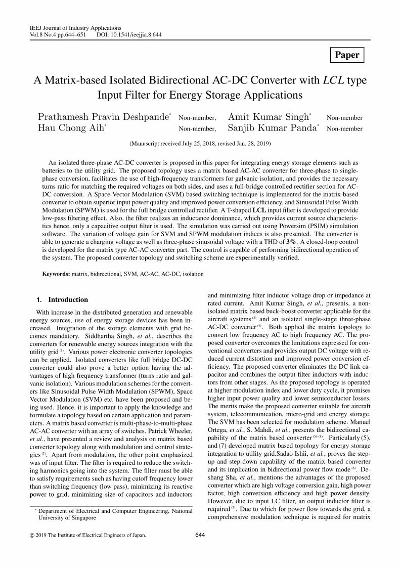
Hence, by using the (9) for reference voltage as the gridvoltage, the control loop is shown in Fig. 6. The correspond-ing results are described in Section 4.2.
4. Results and Discussions
The results obtained from simulation of the converter in thesoftware has been described in this section. Simulation con-sist of two parts, power flow from grid to energy storage de-vice and vice-versa. Along with waveforms for gating pulses,voltages and currents, variation of voltage ratio or gain is pre-sented.
Fig. 7. Grid voltage and drain current respectively
Fig. 8. SVM gating signals (G) for respective matrixbased converter switches
Fig. 9. High frequency transformer voltage and currentrespectively
4.1 Open Loop Operation4.1.1 Charging of the Energy Storage using the Util-
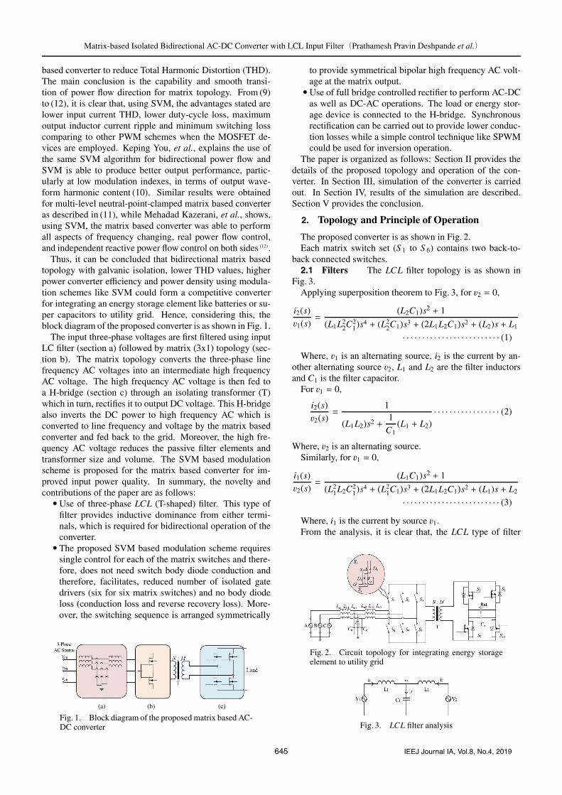
ity Grid Referring to Section 2.3, the purpose of thisconverter is for integration of energy storage element to theutility grid. Hence, the converter has to supply a chargingvoltage and current to the load. The simulation results arethe gating signals for all 6 sets of back-to-back connectedswitches are as shown in Fig. 8, high frequency transformerhigh voltage side voltage and current are shown in Fig. 9 andDC output voltage and current as shown in Fig. 10.
Using simulation, the relation between SVM modulationindex and voltage ratio or gain is determined and as shown inFig. 11. The voltage ratio is defined as the ratio of output DCvoltage or average value to peak value of input phase voltage.
From Fig. 11, the linear nature of the voltage ratio with re-spect to modulation index of SVM is observed. Appropriatemodulation index can be selected to achieve desired outputvoltage. Also, buck nature of the converter for power flowfrom grid to energy storage device can be inferred.
647 IEEJ Journal IA, Vol.8, No.4, 2019
Matrix-based Isolated Bidirectional AC-DC Converter with LCL Input Filter(Prathamesh Pravin Deshpande et al.)
Fig. 10. DC output voltage and current
Fig. 11. Variation of voltage ratio or gain with respectto SVM modulation index
Fig. 12. SVM gating signals (G1 to G6) for respectivematrix based converter switches and SPWM gating sig-nals (G7, G10 and G8, G9) for respective controlled recti-fier switches
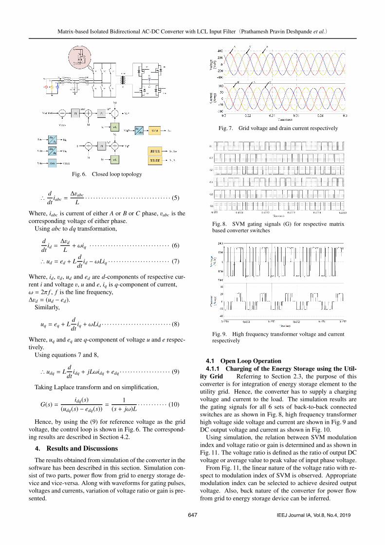
4.1.2 Discharging of the Energy Storage to the UtilityGrid As described in Section 2.4, SPWM is used for theinversion. The main point is that no change of switching tech-nique for the matrix based converter to act for bidirectionalpower flow. The only change is the frequency of referencesignal provided to generate gating pulses. Also, the same car-rier signal is used for both SVM (for matrix) and SPWM (forinverter). The matrix based converter is switched using theSVM signals shown in Fig. 12. The simulated transformergrid side or primary side voltage and current is as shown inFig. 13. The three-phase AC voltage and current developedfrom the matrix based converter is shown in Fig. 14. Usingsimulation, the relation between SVM modulation index (m)and voltage ratio or gain was determined with respect to thatof SPWM (M) and as shown in Fig. 15. The voltage ratio isdefined as the ratio of output phase peak voltage to input DCvoltage of energy storage.
Figure 13 shows the output voltage after the filter. Thetransformer voltage is formulated due to high frequency
Fig. 13. Transformer voltage and current repsectivelywith SVM pulses and output voltage
Fig. 14. Three phase output voltage and current respec-tively in open loop operation
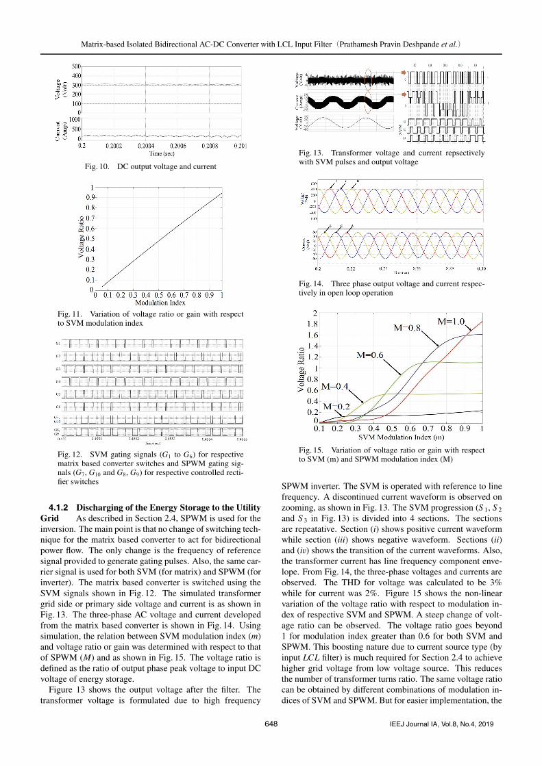
Fig. 15. Variation of voltage ratio or gain with respectto SVM (m) and SPWM modulation index (M)
SPWM inverter. The SVM is operated with reference to linefrequency. A discontinued current waveform is observed onzooming, as shown in Fig. 13. The SVM progression (S 1, S 2
and S 3 in Fig. 13) is divided into 4 sections. The sectionsare repeatative. Section (i) shows positive current waveformwhile section (iii) shows negative waveform. Sections (ii)and (iv) shows the transition of the current waveforms. Also,the transformer current has line frequency component enve-lope. From Fig. 14, the three-phase voltages and currents areobserved. The THD for voltage was calculated to be 3%while for current was 2%. Figure 15 shows the non-linearvariation of the voltage ratio with respect to modulation in-dex of respective SVM and SPWM. A steep change of volt-age ratio can be observed. The voltage ratio goes beyond1 for modulation index greater than 0.6 for both SVM andSPWM. This boosting nature due to current source type (byinput LCL filter) is much required for Section 2.4 to achievehigher grid voltage from low voltage source. This reducesthe number of transformer turns ratio. The same voltage ratiocan be obtained by different combinations of modulation in-dices of SVM and SPWM. But for easier implementation, the
648 IEEJ Journal IA, Vol.8, No.4, 2019
Matrix-based Isolated Bidirectional AC-DC Converter with LCL Input Filter(Prathamesh Pravin Deshpande et al.)
Fig. 16. Three phase output voltage and current respec-tively in closed loop operation
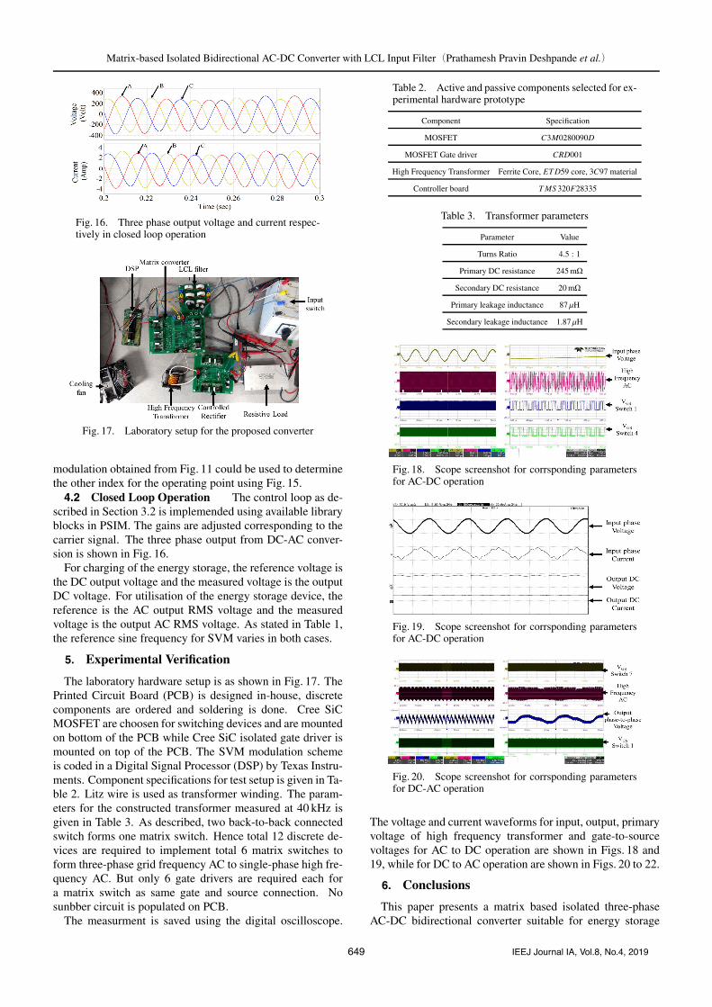
Fig. 17. Laboratory setup for the proposed converter
modulation obtained from Fig. 11 could be used to determinethe other index for the operating point using Fig. 15.4.2 Closed Loop Operation The control loop as de-
scribed in Section 3.2 is implemended using available libraryblocks in PSIM. The gains are adjusted corresponding to thecarrier signal. The three phase output from DC-AC conver-sion is shown in Fig. 16.
For charging of the energy storage, the reference voltage isthe DC output voltage and the measured voltage is the outputDC voltage. For utilisation of the energy storage device, thereference is the AC output RMS voltage and the measuredvoltage is the output AC RMS voltage. As stated in Table 1,the reference sine frequency for SVM varies in both cases.
5. Experimental Verification
The laboratory hardware setup is as shown in Fig. 17. ThePrinted Circuit Board (PCB) is designed in-house, discretecomponents are ordered and soldering is done. Cree SiCMOSFET are choosen for switching devices and are mountedon bottom of the PCB while Cree SiC isolated gate driver ismounted on top of the PCB. The SVM modulation schemeis coded in a Digital Signal Processor (DSP) by Texas Instru-ments. Component specifications for test setup is given in Ta-ble 2. Litz wire is used as transformer winding. The param-eters for the constructed transformer measured at 40 kHz isgiven in Table 3. As described, two back-to-back connectedswitch forms one matrix switch. Hence total 12 discrete de-vices are required to implement total 6 matrix switches toform three-phase grid frequency AC to single-phase high fre-quency AC. But only 6 gate drivers are required each fora matrix switch as same gate and source connection. Nosunbber circuit is populated on PCB.
The measurment is saved using the digital oscilloscope.
Table 2. Active and passive components selected for ex-perimental hardware prototype
Component Specification
MOSFET C3M0280090D
MOSFET Gate driver CRD001
High Frequency Transformer Ferrite Core, ET D59 core, 3C97 material
Controller board T MS 320F28335
Table 3. Transformer parameters
Parameter Value
Turns Ratio 4.5 : 1
Primary DC resistance 245 mΩ
Secondary DC resistance 20 mΩ
Primary leakage inductance 87 μH
Secondary leakage inductance 1.87 μH
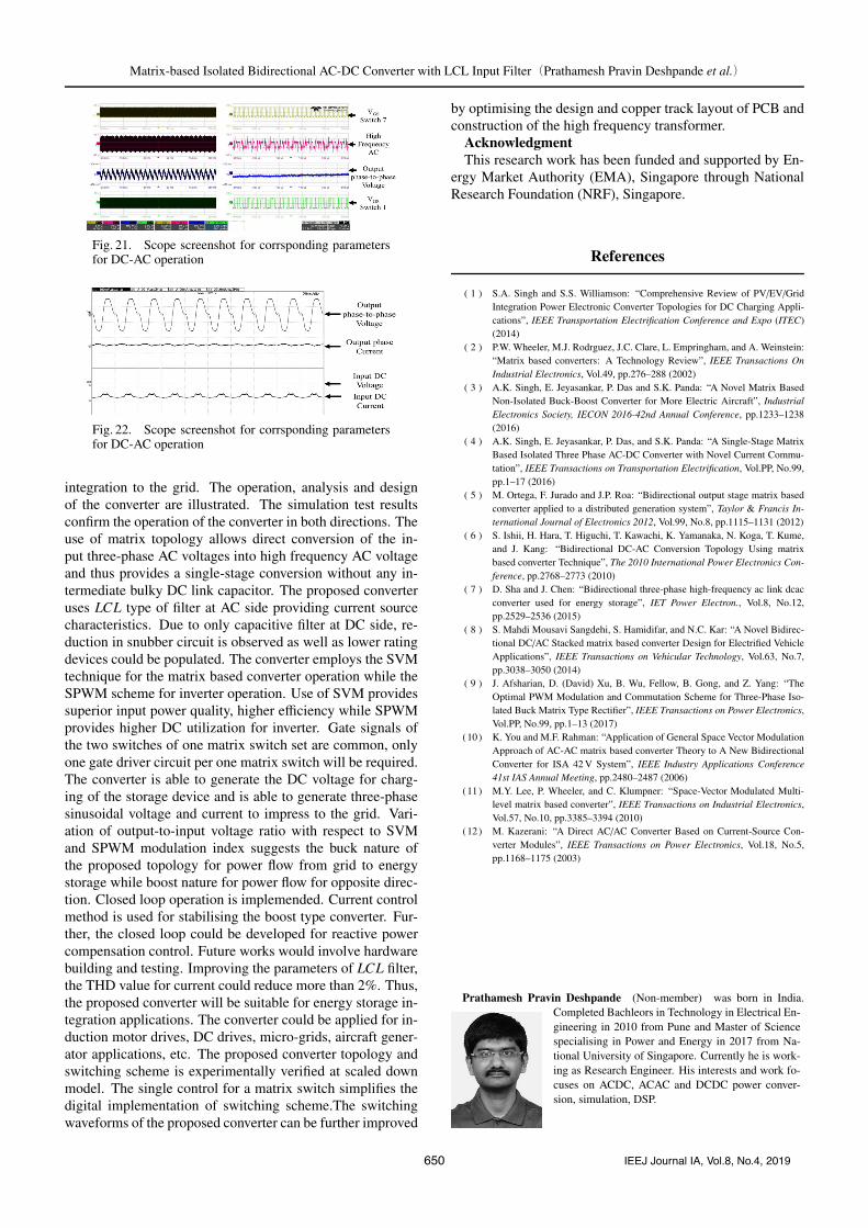
Fig. 18. Scope screenshot for corrsponding parametersfor AC-DC operation
Fig. 19. Scope screenshot for corrsponding parametersfor AC-DC operation
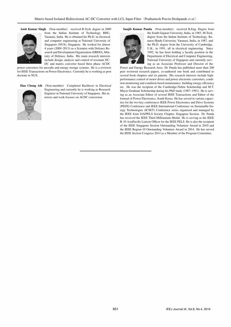
Fig. 20. Scope screenshot for corrsponding parametersfor DC-AC operation
The voltage and current waveforms for input, output, primaryvoltage of high frequency transformer and gate-to-sourcevoltages for AC to DC operation are shown in Figs. 18 and19, while for DC to AC operation are shown in Figs. 20 to 22.
6. Conclusions
This paper presents a matrix based isolated three-phaseAC-DC bidirectional converter suitable for energy storage
649 IEEJ Journal IA, Vol.8, No.4, 2019
Matrix-based Isolated Bidirectional AC-DC Converter with LCL Input Filter(Prathamesh Pravin Deshpande et al.)
Fig. 21. Scope screenshot for corrsponding parametersfor DC-AC operation
Fig. 22. Scope screenshot for corrsponding parametersfor DC-AC operation
integration to the grid. The operation, analysis and designof the converter are illustrated. The simulation test resultsconfirm the operation of the converter in both directions. Theuse of matrix topology allows direct conversion of the in-put three-phase AC voltages into high frequency AC voltageand thus provides a single-stage conversion without any in-termediate bulky DC link capacitor. The proposed converteruses LCL type of filter at AC side providing current sourcecharacteristics. Due to only capacitive filter at DC side, re-duction in snubber circuit is observed as well as lower ratingdevices could be populated. The converter employs the SVMtechnique for the matrix based converter operation while theSPWM scheme for inverter operation. Use of SVM providessuperior input power quality, higher efficiency while SPWMprovides higher DC utilization for inverter. Gate signals ofthe two switches of one matrix switch set are common, onlyone gate driver circuit per one matrix switch will be required.The converter is able to generate the DC voltage for charg-ing of the storage device and is able to generate three-phasesinusoidal voltage and current to impress to the grid. Vari-ation of output-to-input voltage ratio with respect to SVMand SPWM modulation index suggests the buck nature ofthe proposed topology for power flow from grid to energystorage while boost nature for power flow for opposite direc-tion. Closed loop operation is implemended. Current controlmethod is used for stabilising the boost type converter. Fur-ther, the closed loop could be developed for reactive powercompensation control. Future works would involve hardwarebuilding and testing. Improving the parameters of LCL filter,the THD value for current could reduce more than 2%. Thus,the proposed converter will be suitable for energy storage in-tegration applications. The converter could be applied for in-duction motor drives, DC drives, micro-grids, aircraft gener-ator applications, etc. The proposed converter topology andswitching scheme is experimentally verified at scaled downmodel. The single control for a matrix switch simplifies thedigital implementation of switching scheme.The switchingwaveforms of the proposed converter can be further improved
by optimising the design and copper track layout of PCB andconstruction of the high frequency transformer.
AcknowledgmentThis research work has been funded and supported by En-
ergy Market Authority (EMA), Singapore through NationalResearch Foundation (NRF), Singapore.
References
( 1 ) S.A. Singh and S.S. Williamson: “Comprehensive Review of PV/EV/GridIntegration Power Electronic Converter Topologies for DC Charging Appli-cations”, IEEE Transportation Electrification Conference and Expo (ITEC)(2014)
( 2 ) P.W. Wheeler, M.J. Rodrguez, J.C. Clare, L. Empringham, and A. Weinstein:“Matrix based converters: A Technology Review”, IEEE Transactions OnIndustrial Electronics, Vol.49, pp.276–288 (2002)
( 3 ) A.K. Singh, E. Jeyasankar, P. Das and S.K. Panda: “A Novel Matrix BasedNon-Isolated Buck-Boost Converter for More Electric Aircraft”, IndustrialElectronics Society, IECON 2016-42nd Annual Conference, pp.1233–1238(2016)
( 4 ) A.K. Singh, E. Jeyasankar, P. Das, and S.K. Panda: “A Single-Stage MatrixBased Isolated Three Phase AC-DC Converter with Novel Current Commu-tation”, IEEE Transactions on Transportation Electrification, Vol.PP, No.99,pp.1–17 (2016)
( 5 ) M. Ortega, F. Jurado and J.P. Roa: “Bidirectional output stage matrix basedconverter applied to a distributed generation system”, Taylor & Francis In-ternational Journal of Electronics 2012, Vol.99, No.8, pp.1115–1131 (2012)
( 6 ) S. Ishii, H. Hara, T. Higuchi, T. Kawachi, K. Yamanaka, N. Koga, T. Kume,and J. Kang: “Bidirectional DC-AC Conversion Topology Using matrixbased converter Technique”, The 2010 International Power Electronics Con-ference, pp.2768–2773 (2010)
( 7 ) D. Sha and J. Chen: “Bidirectional three-phase high-frequency ac link dcacconverter used for energy storage”, IET Power Electron., Vol.8, No.12,pp.2529–2536 (2015)
( 8 ) S. Mahdi Mousavi Sangdehi, S. Hamidifar, and N.C. Kar: “A Novel Bidirec-tional DC/AC Stacked matrix based converter Design for Electrified VehicleApplications”, IEEE Transactions on Vehicular Technology, Vol.63, No.7,pp.3038–3050 (2014)
( 9 ) J. Afsharian, D. (David) Xu, B. Wu, Fellow, B. Gong, and Z. Yang: “TheOptimal PWM Modulation and Commutation Scheme for Three-Phase Iso-lated Buck Matrix Type Rectifier”, IEEE Transactions on Power Electronics,Vol.PP, No.99, pp.1–13 (2017)
(10) K. You and M.F. Rahman: “Application of General Space Vector ModulationApproach of AC-AC matrix based converter Theory to A New BidirectionalConverter for ISA 42 V System”, IEEE Industry Applications Conference41st IAS Annual Meeting, pp.2480–2487 (2006)
(11) M.Y. Lee, P. Wheeler, and C. Klumpner: “Space-Vector Modulated Multi-level matrix based converter”, IEEE Transactions on Industrial Electronics,Vol.57, No.10, pp.3385–3394 (2010)
(12) M. Kazerani: “A Direct AC/AC Converter Based on Current-Source Con-verter Modules”, IEEE Transactions on Power Electronics, Vol.18, No.5,pp.1168–1175 (2003)
Prathamesh Pravin Deshpande (Non-member) was born in India.Completed Bachleors in Technology in Electrical En-gineering in 2010 from Pune and Master of Sciencespecialising in Power and Energy in 2017 from Na-tional University of Singapore. Currently he is work-ing as Research Engineer. His interests and work fo-cuses on ACDC, ACAC and DCDC power conver-sion, simulation, DSP.
650 IEEJ Journal IA, Vol.8, No.4, 2019
Matrix-based Isolated Bidirectional AC-DC Converter with LCL Input Filter(Prathamesh Pravin Deshpande et al.)
Amit Kumar Singh (Non-member) received B.Tech. degree in 2009from the Indian Institute of Technology BHU,Varanasi, India. He is obtained his Ph.D. in electricaland computer engineering at National University ofSingapore (NUS), Singapore. He worked for almost4 years (2009–2013) as a Scientist with Defence Re-search and Development Organization (DRDO), Min-istry of Defence, India. His main research interestsinclude design, analysis and control of resonant DC-DC and matrix converter based three phase ACDC
power converters for aircrafts and energy storage systems. He is a reviewerfor IEEE Transactions on Power Electronics. Currently he is working as postdoctrate in NUS.
Hau Chong Aih (Non-member) Completed Bachleors in ElectricalEngineering and currently he is working as ResearchEngineer in National University of Singapore. His in-terests and work focuses on ACDC conversion.
Sanjib Kumar Panda (Non-member) received B.Eng. Degree fromthe South Gujarat University, India, in 1983, M.Tech.degree from the Indian Institute of Technology, Ba-naras Hindu University, Varanasi, India, in 1987, andthe Ph.D. degree from the University of Cambridge,U.K., in 1991, all in electrical engineering. Since1992, he has been holding a faculty position in theDepartment of Electrical and Computer Engineering,National University of Singapore and currently serv-ing as an Associate Professor and Director of the
Power and Energy Research Area. Dr. Panda has published more than 200peer reviewed research papers, co-authored one book and contributed toseveral book chapters and six patents. His research interests include high-performance control of motor drives and power electronic converters, condi-tion monitoring and condition based maintenance, building energy efficiencyetc. He was the recipient of the Cambridge-Nehru Scholarship and M.T.Mayer Graduate Scholarship during his PhD study (1987–1991). He is serv-ing as an Associate Editor of several IEEE Transactions and Editor of theJournal of Power Electronics, South Korea. He has served in various capaci-ties for the two key conferences IEEE Power Electronics and Drive Systems(PEDS) Conference and IEEE International Conference on Sustainable En-ergy Technologies (ICSET) Conference series organized and managed bythe IEEE Joint IAS/PELS Society Chapter, Singapore Section. Dr. Pandahas received the IEEE Third Millennium Medal. He is serving as the IEEER-10 AsiaPacific Liaison Officer for the IEEE PELS. He is also the recipientof the IEEE Singapore Section Outstanding Volunteer Award in 2010 andthe IEEE Region-10 Outstanding Volunteer Award in 2014. He has servedthe IEEE Section Congress 2014 as a Member of the Program Committee.
651 IEEJ Journal IA, Vol.8, No.4, 2019